Movatterモバイル変換


[0]ホーム

URL:


JP2005167379A - Speaker system - Google Patents

Speaker system
Download PDF

Info

Publication number
JP2005167379A
JP2005167379AJP2003400175AJP2003400175AJP2005167379AJP 2005167379 AJP2005167379 AJP 2005167379AJP 2003400175 AJP2003400175 AJP 2003400175AJP 2003400175 AJP2003400175 AJP 2003400175AJP 2005167379 AJP2005167379 AJP 2005167379A
Authority
JP
Japan
Prior art keywords
speaker
sound
housing
speaker device
opening
Prior art date
Legal status (The legal status is an assumption and is not a legal conclusion. Google has not performed a legal analysis and makes no representation as to the accuracy of the status listed.)
Withdrawn
Application number
JP2003400175A
Other languages
Japanese (ja)
Inventor
Shinji Kobayashi
真治 小林
Current Assignee (The listed assignees may be inaccurate. Google has not performed a legal analysis and makes no representation or warranty as to the accuracy of the list.)
Sony Corp
Original Assignee
Sony Corp
Priority date (The priority date is an assumption and is not a legal conclusion. Google has not performed a legal analysis and makes no representation as to the accuracy of the date listed.)
Filing date
Publication date
Application filed by Sony CorpfiledCriticalSony Corp
Priority to JP2003400175ApriorityCriticalpatent/JP2005167379A/en
Publication of JP2005167379ApublicationCriticalpatent/JP2005167379A/en
Withdrawnlegal-statusCriticalCurrent

Links

Images

Landscapes

Abstract

<P>PROBLEM TO BE SOLVED: To provide a speaker system enabling a passenger sitting on each seat to listen to music and the like emitted from an individually selected sound source with satisfactory sound quality by preventing sound leakage to the periphery. <P>SOLUTION: A speaker system is composed of units 10R, 10L mounted on headrest shafts 5, 6 for supporting a headrest 4. In this system, a reproduced sound emitted from a speaker 13 is reflected to the side by a main reflector 21 and a side reflector 22 which are provided at an opening of a housing 12 of a speaker unit 14 having a built-in speaker 13, and the sound is emitted from a sound emitting opening 24 formed so as to face the ears of the passenger M. <P>COPYRIGHT: (C)2005,JPO&NCIPI

Description

Translated fromJapanese

本発明は、自動車等の車両の各座席に対して個別に着脱されることによって、当該座席に座った搭乗者が個々に音源からの再生音を視聴可能とするスピーカ装置に関する。  The present invention relates to a speaker device that can be individually attached to and detached from each seat of a vehicle such as an automobile so that a passenger sitting on the seat can individually view reproduced sound from a sound source.

自動車には、音源として例えばラジオ放送やテレビジョン放送等を受信するチューナ、ディスクプレィヤ或いはカセットテーププレィヤ等の各種オーディオ装置が搭載され、車内に適宜設置したスピーカによって再生音が視聴される。また、自動車には、その他の音源として例えば内蔵スピーカから音声ガイドが行われるカーナビゲーション装置や搭乗者によって持ち込まれた携帯型オーディオ装置や携帯電話機等も存在する。なお、カーナビゲーション装置においては、高機能、多機能化に伴ってオーディオ機能を搭載したものも提供されている。  Various types of audio devices such as tuners, disk players, cassette tape players, and the like that receive radio broadcasts, television broadcasts, and the like as sound sources are mounted on automobiles, and reproduced sounds are viewed through speakers appropriately installed in the vehicle. In addition, automobiles include car navigation devices in which voice guidance is performed from a built-in speaker, portable audio devices brought by passengers, mobile phones, and the like as other sound sources. Some car navigation apparatuses are equipped with an audio function as the functions become higher and multifunctional.

自動車等においては、上述したように各種の音源が備えられているが、例えば運転手が選択した音源からの再生信号がスピーカから放音されることから同乗者が同一の再生音を視聴することになる。同乗者は、個人で好みの音楽等を聴取したい時には、例えば持ち込んだ携帯型オーディオ装置によって好みの音楽等をヘッドホンによって視聴していた。  In automobiles and the like, various sound sources are provided as described above. For example, a reproduction signal from a sound source selected by a driver is emitted from a speaker, so that a passenger can view the same reproduced sound. become. When a passenger wants to listen to his / her favorite music or the like, he / she listened to his / her favorite music or the like with headphones using a portable audio device he / she brought.

一方、自動車等においては、フロント部やリア部等の適宜の位置にそれぞれ設置した固定スピーカに加えて、各座席のヘッドレスト内にスピーカを組み込むことによって車内にダイナミックな音場を構成する音響システムも提案されている(例えば、特許文献1乃至特許文献3)。また、自動車等においては、各座席のヘッドレストを支持するヘッドレスト軸を利用してスピーカを設置することも提案されている(例えば、特許文献4及び特許文献5)。  On the other hand, in automobiles, in addition to fixed speakers installed at appropriate positions such as the front and rear parts, there is also an acoustic system that forms a dynamic sound field in the car by incorporating speakers in the headrest of each seat. It has been proposed (for example,Patent Documents 1 to 3). In addition, in automobiles and the like, it has also been proposed to install a speaker using a headrest shaft that supports the headrest of each seat (for example,Patent Document 4 and Patent Document 5).

さらに、特許文献6には、上述した各特許文献と同様に自動車の各座席に設けたヘッドレスト内にスピーカが組み込まれており、このスピーカの放音部位に反射カバーを設けて搭乗者の耳元に向かって放音を行うようにした音響装置が開示されている。  Further, inPatent Document 6, a speaker is incorporated in a headrest provided in each seat of an automobile in the same manner as in each of the above-described Patent Documents, and a reflective cover is provided at a sound emitting portion of the speaker to be close to a passenger's ear. An acoustic device is disclosed that emits sound toward the front.

特開平8−289389号公報JP-A-8-289389特開平9−171387号公報JP-A-9-171387実開昭55−109450号公報Japanese Utility Model Publication No. 55-109450実開昭61−165853号公報Japanese Utility Model Publication No. 61-165853特開平9−286285号公報JP-A-9-286285特開昭61−131998号公報Japanese Patent Laid-Open No. 61-131998

上述した各ヘッドレストスピーカにおいては、車内における座席の位置による音質や音量等のバラツキを補正した最適な音場を構成して各搭乗者に対して個別に良好な再生音を視聴することを可能とする。また、ヘッドレストスピーカにおいては、例えば座席毎に音源の選択を可能とするように構成することによって、同乗者がヘッドホンを装着する煩わしさを無くして個別に好みの音楽等を視聴することを可能とする。  In each headrest speaker described above, it is possible to configure an optimal sound field that corrects variations in sound quality, volume, etc. depending on the position of the seat in the car, and allows each passenger to view good reproduction sound individually. To do. In addition, the headrest speaker can be configured so that, for example, a sound source can be selected for each seat, so that passengers can individually view their favorite music without the hassle of wearing headphones. To do.

ヘッドレストスピーカにおいては、各搭乗者の耳元近くで再生音の放音が行われることから、異なる音源が選択されて再生が行われている他の座席からの再生音もさほど気にならないようになる。しかしながら、ヘッドレストスピーカにおいては、スピーカからの音漏れが生じるために、音量を控えて聴取する配慮が必要であった。  In the headrest speaker, since the playback sound is emitted near the ears of each passenger, the playback sound from other seats where playback is being performed with a different sound source selected is less concerned . However, in the headrest speaker, since sound leakage from the speaker occurs, it is necessary to consider listening with a reduced volume.

また、一般的なスピーカ装置は、放音部の中心軸を視聴者の耳孔に対して平行となるように設置することによって、効率のよい音圧レベル(SPL:Sound Pressure Level)特性が得られるようになる。また、一般的なスピーカ装置は、スピーカの放音部の近くで再生音を直接聴取するような場合に、ひずみが生じる特性がある。上述した各ヘッドレストスピーカにおいては、座席に座った各搭乗者に対してかかる音圧レベル特性や音質レベル特性を保持することが困難であった。  In addition, a general speaker device can obtain an efficient sound pressure level (SPL) characteristic by installing the central axis of the sound emitting part so as to be parallel to the ear hole of the viewer. It becomes like this. In addition, a general speaker device has a characteristic that distortion occurs when a reproduced sound is directly listened to near the sound emitting portion of the speaker. In each of the headrest speakers described above, it is difficult to maintain the sound pressure level characteristic and the sound quality level characteristic applied to each passenger sitting on the seat.

上述したヘッドレスト内蔵型のスピーカ装置は、各座席に対して設置した場合にシステム全体を高価にするとともに車種毎に設計されるヘッドレストに適合するように構成されなければならないために、高級グレード車にのみ設置されて汎用性が無い。また、かかるスピーカ装置は、全ての座席に設置した場合に利用効率も悪く、また設置されていない座席に座った搭乗者が利用することができないといった問題があった。  The above-mentioned built-in headrest type speaker device makes the entire system expensive when installed for each seat and must be configured to fit the headrest designed for each vehicle type. Only installed and not versatile. In addition, such a speaker device has a problem in that it is not used efficiently when installed in all seats and cannot be used by a passenger sitting in a seat that is not installed.

上述したヘッドレスト着脱型のスピーカ装置は、比較的廉価で製作されるとともに既存車に対しても必要に応じて設置することが可能である。しかしながら、かかるスピーカ装置は、ある程度の出力性能を有するようにすると大型となって座席からの突出量も大きくなってしまうために未使用時には邪魔になりまた万一の場合に搭乗者がぶっかって危険であるといった問題がある。  The headrest detachable speaker device described above is manufactured at a relatively low cost and can be installed on an existing vehicle as required. However, such a speaker device has a large size and a large amount of protrusion from the seat if it has a certain level of output performance. Therefore, it becomes a hindrance when not in use, and it is dangerous for a passenger to hit in the unlikely event. There is a problem such as.

さらに、上述したいずれのスピーカ装置も、座席に対して固定された位置に設置されることから、体型を異にする様々な搭乗者の耳元に対して最適位置に対向して設置させることが困難であった。スピーカ装置は、特に小さな子供が座席に座った場合に、耳元から大きく離れてしまうために、上述した特徴を全く発揮することができず、周囲への音漏れも大きくなるといった問題があった。  Furthermore, since any of the above-described speaker devices is installed at a position fixed with respect to the seat, it is difficult to install the speaker device facing the optimum position with respect to the ears of various passengers having different body shapes. Met. The speaker device has a problem in that, when a small child sits on the seat, the speaker device is far away from the ear, so that the above-described features cannot be exhibited at all, and sound leakage to the surroundings increases.

したがって、本発明は、各座席に座った搭乗者がそれぞれ個別に選択した音源から放音される音楽等を、周囲への音漏れを抑制しかつ良好な音質で視聴することを可能とするスピーカ装置を提供することを目的とする。  Therefore, the present invention is a speaker that enables to listen to music and the like emitted from sound sources individually selected by passengers sitting in each seat with good sound quality while suppressing sound leakage to the surroundings. An object is to provide an apparatus.

上述した目的を達成する本発明にかかるスピーカ装置は、座席に対してヘッドレストを高さ調整自在に支持する一対のヘッドレスト軸にそれぞれ取り付けられることによって上記座席に座った搭乗者の両耳にそれぞれ対向して設置される左右一対のユニットによって構成される。本発明にかかるスピーカ装置は、各ユニットが、適宜の音源から再生信号が入力される入力部と、スピーカユニットと、ヘッドレスト軸に対して着脱される取付部材と、一端部をスピーカユニットのハウジングに固定されるとともに他端部を取付部材に固定されてスピーカユニットを座席に座った搭乗者の耳元に対向させる支持アーム部とを備えて構成される。本発明にかかるスピーカ装置は、スピーカユニットが、設置状態において搭乗者の顔の向きの方向と平行な方向に開口する開口部を有するハウジングと、このハウジング内に取り付けられて再生信号を再生して開口部に向けて放音するスピーカと、ハウジングの開口部に搭乗者の耳元に向かって次第に対向間隔を大きくするようにして傾斜状態で設けられることによってスピーカから放音された再生音を搭乗者の耳元側に向かって反射させるメインリフレクタと、このメインリフレクタに設けられてハウジングとの間に搭乗者の耳元と対向する部位を開口させて放音開口部を構成する円弧状のサイドリフレクタとから構成される。  The speaker device according to the present invention that achieves the above-described object is mounted on a pair of headrest shafts that support the headrest so that the height of the headrest is adjustable with respect to the seat, thereby facing the both ears of the passenger sitting on the seat. And a pair of left and right units installed. In the speaker device according to the present invention, each unit includes an input unit to which a reproduction signal is input from an appropriate sound source, a speaker unit, a mounting member that is attached to and detached from the headrest shaft, and one end portion of the unit to the housing of the speaker unit. And a support arm portion that is fixed and has the other end portion fixed to the attachment member and that faces the ears of the passenger sitting on the seat. In the speaker device according to the present invention, the speaker unit has a housing having an opening that opens in a direction parallel to the direction of the face of the occupant in the installed state, and is mounted in the housing to reproduce a reproduction signal. A speaker that emits sound toward the opening, and a reproduction sound emitted from the speaker by being provided in an inclined state in the opening of the housing so as to gradually increase the facing distance toward the ear of the passenger A main reflector that reflects toward the ear side of the vehicle, and an arc-shaped side reflector that is provided on the main reflector and opens a portion facing the passenger's ear between the housing and an arc-shaped side reflector that forms a sound emission opening Composed.

本発明にかかるスピーカ装置においては、取付部材を介して各支持アーム部の一端部を相対するヘッドレスト軸に固定することによってそれぞれ車内の各座席毎に設置され、スピーカユニットが座席に座った搭乗者の耳元に対向されるようにする。本発明にかかるスピーカ装置においては、入力部が適宜の音源と接続され、当該座席に座った搭乗者により選択された再生信号に基づく再生音が再生されてスピーカユニットから放音される。本発明にかかるスピーカ装置においては、スピーカからの再生音が搭乗者の顔の向きの方向と平行な方向に開口するハウジングの開口部から放音されるが、ハウジングに設けたメインリフレクタによって搭乗者の耳元と対向して開口された放音開口部側へと反射されて搭乗者の耳孔と平行な方向に放音される。また、本発明にかかるスピーカ装置においては、ハウジングとメインリフレクタとの間に介在するサイドリフレクタが、搭乗者の耳元と対向する限られた領域で開口する放音開口部を構成してなる。  In the speaker device according to the present invention, a passenger who is installed in each seat in the vehicle by fixing one end portion of each support arm portion to the opposite headrest shaft via an attachment member, and the speaker unit is seated in the seat Be sure to face the ears. In the speaker device according to the present invention, the input unit is connected to an appropriate sound source, and the reproduction sound based on the reproduction signal selected by the passenger sitting on the seat is reproduced and emitted from the speaker unit. In the speaker device according to the present invention, the reproduced sound from the speaker is emitted from the opening of the housing that opens in a direction parallel to the direction of the occupant's face, but the passenger is provided by the main reflector provided in the housing. The sound is reflected toward the sound emission opening that is opened opposite to the ear of the vehicle and emitted in a direction parallel to the ear hole of the passenger. In the speaker device according to the present invention, the side reflector interposed between the housing and the main reflector forms a sound emitting opening that opens in a limited region facing the passenger's ear.

以上のように構成された本発明にかかるスピーカ装置によれば、既設の車両にも、取付部材をヘッドレスト軸に固定する簡易な操作によって任意の座席に対して必要に応じて設置され、当該座席に座った搭乗者を対象として例えば個別に選択した音源からの再生信号に基づく再生音を放音して隣の座席との間で再生音の干渉を低減して視聴することを可能とする。本発明にかかるスピーカ装置によれば、スピーカユニットがハウジングの開口部を正面側に向かって開口するように配置されてメインリフレクタによって再生音を反射させることから、搭乗者のサイド視野を確保させるとともに、ハウジング内での音籠もりやひずみの発生を抑制して良好な音質での視聴を可能とさせる。本発明にかかるスピーカ装置によれば、サイドリフレクタによって周囲への音漏れを抑制するとともに充分な音圧レベルが保持されることによって指向性が高められて放音開口部から再生音の放音が行われるようになる。  According to the speaker device according to the present invention configured as described above, an existing vehicle can be installed as needed with respect to any seat by a simple operation of fixing the mounting member to the headrest shaft. For example, it is possible to release a reproduction sound based on a reproduction signal from an individually selected sound source and reduce the interference of the reproduction sound with an adjacent seat and view the passenger sitting on the seat. According to the speaker device of the present invention, the speaker unit is arranged so that the opening of the housing opens toward the front side and the reproduced sound is reflected by the main reflector, so that the side view of the passenger is secured. In addition, it is possible to view with good sound quality by suppressing the generation of noise and distortion in the housing. According to the speaker device of the present invention, sound leakage to the surroundings is suppressed by the side reflector and a sufficient sound pressure level is maintained, so that directivity is enhanced and sound of reproduced sound is emitted from the sound emission opening. To be done.

以下、本発明の実施の形態として図面に示したスピーカ装置1について、詳細に説明する。スピーカ装置1は、図1及び図2に示すように自動車2の各座席3a〜3d(以下、座席3と総称する。)に対して、必要に応じて後付け操作によってこれらの全部の座席或いは選択した任意の座席に設置して用いられる。スピーカ装置1は、自動車2に搭載された放送受信用チューナ、ディスクプレィヤ或いはカセットテーププレィヤ等の車載オーディオ装置やカーナビゲーション装置或いは搭乗者が車内に持ち込んだ携帯型オーディオ装置等の適宜の音源と接続され、当該座席3に座った搭乗者が上述した各音源から出力される再生信号に基づく再生音を個別に視聴することを可能とする。  Hereinafter, aspeaker device 1 shown in the drawings as an embodiment of the present invention will be described in detail. As shown in FIGS. 1 and 2, thespeaker device 1 is configured so that all seats or selections can be made by retrofitting the seats 3 a to 3 d (hereinafter collectively referred to as seats 3) of theautomobile 2 as necessary. It is installed and used in any seat. Thespeaker device 1 is an appropriate sound source such as a broadcast receiving tuner, a disk player or a cassette tape player mounted on theautomobile 2, a car navigation device, or a portable audio device brought into the vehicle by a passenger. And the passenger sitting on theseat 3 can individually view the reproduction sound based on the reproduction signal output from each sound source described above.

スピーカ装置1は、各座席3に対してそれぞれヘッドレスト4a〜4d(以下、ヘッドレスト4と総称する。)をその高さ位置が調整自在とするようにして支持する左右一対の第1ヘッドレスト軸5或いは第2ヘッドレスト軸6に対して必要に応じて設置されて用いられる。第1ヘッドレスト軸5及び第2ヘッドレスト軸6は、詳細を省略するが下端部が互いに連結されるようにして座席3内に設けられたガイドに沿っそれぞれて昇降自在に組み合わされている。第1ヘッドレスト軸5及び第2ヘッドレスト軸6は、座席3から所定の位置まで引き出した状態においてロック機構によってロックされることにより、ヘッドレスト4を座席3から所定の高さ位置に保持する。  Thespeaker device 1 supports a pair of left and rightfirst headrest shafts 5 that support headrests 4a to 4d (hereinafter collectively referred to as headrests 4) with respect to eachseat 3 so that their height positions are adjustable. Thesecond headrest shaft 6 is installed and used as necessary. Although not described in detail, thefirst headrest shaft 5 and thesecond headrest shaft 6 are combined so as to be movable up and down along guides provided in theseat 3 so that the lower ends thereof are connected to each other. Thefirst headrest shaft 5 and thesecond headrest shaft 6 are locked by a locking mechanism in a state where thefirst headrest shaft 5 and thesecond headrest shaft 6 are pulled out from theseat 3 to a predetermined position, thereby holding theheadrest 4 at a predetermined height position from theseat 3.

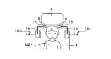
スピーカ装置1は、図2に示すように第1ヘッドレスト軸5及び第2ヘッドレスト軸6を座席3からやや引き出して露出させた状態で取り付けられる。スピーカ装置1は、左右一対の第1ユニット10Rと第2ユニット10Lとから構成される。なお、スピーカ装置1は、これら第1ユニット10Rと第2ユニット10Lとが左右対称に構成されることから、以下単にユニット10と総称して説明する。  Thespeaker device 1 is attached in a state where thefirst headrest shaft 5 and thesecond headrest shaft 6 are slightly pulled out of theseat 3 and exposed as shown in FIG. Thespeaker device 1 includes a pair of left and rightfirst units 10R and asecond unit 10L. Note that thespeaker device 1 will be simply referred to as aunit 10 in the following because thefirst unit 10R and thesecond unit 10L are configured symmetrically.

スピーカ装置1は、各ユニット10が、上述した各音源と接続される入力部11と、ハウジング12及びスピーカ13とからなるスピーカユニット14と、第1ヘッドレスト軸5又は第2ヘッドレスト軸6に対して着脱される取付部15と、支持アーム部16とから構成される。スピーカ装置1は、各ユニット10が第1ヘッドレスト軸5及び第2ヘッドレスト軸6に取り付けられた状態において、図1に示すように各スピーカユニット14を座席3に座った搭乗者Mの耳元に近接して対向されるようにして用いられる。  In thespeaker device 1, eachunit 10 is connected to theinput unit 11 connected to each sound source described above, thespeaker unit 14 including thehousing 12 and thespeaker 13, and thefirst headrest shaft 5 or thesecond headrest shaft 6. The mountingportion 15 is detachably attached to thesupport arm portion 16. In the state where eachunit 10 is attached to thefirst headrest shaft 5 and thesecond headrest shaft 6, thespeaker device 1 is close to the ears of the passenger M sitting on theseat 3 as shown in FIG. 1. And are used so as to face each other.

スピーカ装置1は、詳細を後述するように独立に構成された入力部11とスピーカユニット14とを支持アーム部16を介して連結したことによって、例えばやや大型のスピーカ13を内蔵するようにしてもスピーカユニット14が全体として小型化が図られて構成されてなる。なお、スピーカ装置1は、例えば駆動電源として車載バッテリを利用するとともに車載オーディオ装置等に設けた出力端子と直結して用いることによって入力部11の小型化が図られる場合には、この入力部11の機能の一部をスピーカユニット14に内蔵するようにしてよい。  Thespeaker device 1 may be configured to incorporate, for example, a slightlylarger speaker 13 by connecting theinput unit 11 and thespeaker unit 14 configured independently as will be described in detail later via asupport arm unit 16. Thespeaker unit 14 is configured to be downsized as a whole. Note that thespeaker device 1 uses, for example, an in-vehicle battery as a driving power source and is directly connected to an output terminal provided in the in-vehicle audio device or the like, so that theinput unit 11 can be reduced in size. A part of these functions may be built in thespeaker unit 14.

入力部11は、図2及び図3に示すようにケース17を有しており、スピーカユニット14と再生信号を供給する一対の再生信号供給コード18aによって接続されている。入力部11には、詳細を省略するがケース17にフックやクリップ構造からなる適宜の取付部が形成されており、この取付部によって車内の適宜の箇所に設置されようにする。入力部11は、再生信号供給コード18aが、スピーカ装置1を各ヘッドレスト軸5、6に取り付けた状態で、ケース17の設置箇所から充分にとどく余裕のある長さを有している。  Theinput unit 11 includes acase 17 as shown in FIGS. 2 and 3, and is connected to thespeaker unit 14 by a pair of reproduction signal supply cords 18a for supplying a reproduction signal. Although not described in detail, theinput portion 11 is provided with an appropriate attachment portion formed of a hook or a clip structure on thecase 17 and is installed at an appropriate location in the vehicle by the attachment portion. In theinput unit 11, the reproduction signal supply cord 18 a has a sufficient length to reach from the installation location of thecase 17 in a state where thespeaker device 1 is attached to theheadrest shafts 5 and 6.

なお、入力部11は、第1ユニット10Rと第2ユニット10Lとにそれぞれ独立して設けたが、例えば第2ユニット10L側の再生信号供給コード18aを第1ユニット10R側のケース17に導くことによって、1個のケース17によって構成するようにしてもよい。入力部11は、ケース17から再生信号入力コード18bが引き出されており、この再生信号入力コード18bの先端に設けたピンプラグ19が上述した各音源と接続されることによって再生信号が供給される。  Although theinput unit 11 is provided independently for each of thefirst unit 10R and thesecond unit 10L, for example, the reproduction signal supply cord 18a on thesecond unit 10L side is guided to thecase 17 on thefirst unit 10R side. Thus, it may be configured by onecase 17. The reproductionsignal input code 18b is drawn from thecase 17 to theinput unit 11, and a reproduction signal is supplied by connecting thepin plug 19 provided at the tip of the reproductionsignal input code 18b to each sound source described above.

なお、入力部11には、ケース17の内部に電源用の乾電池或いは二次電池が収納されるとともに、電源回路やアンプ回路等を搭載した回路基板が収納されている。入力部11には、音源の選択部やボリューム等のコントロール部を設けるようにしてよい。スピーカ装置1においては、入力部11のケース17内に例えば赤外線等を利用した無線受信回路を搭載することにより、上述した再生信号入力コード18bとピンプラグ19に代えて或いはこれらに加えて例えば車載オーディオ装置側から無線によって再生信号が供給されるように構成してもよい。スピーカ装置1においては、入力部11とスピーカユニット14との間で再生信号の送受信を無線によって行うようにしてもよい。  Note that theinput unit 11 houses a dry battery or a secondary battery for power supply inside thecase 17 and a circuit board on which a power circuit, an amplifier circuit, and the like are mounted. Theinput unit 11 may be provided with a sound source selection unit and a control unit such as a volume. In thespeaker device 1, for example, in-vehicle audio can be used instead of or in addition to the reproductionsignal input cord 18 b and thepin plug 19 described above by mounting a wireless receiving circuit using, for example, infrared rays or the like in thecase 17 of theinput unit 11. A reproduction signal may be supplied wirelessly from the device side. In thespeaker device 1, a reproduction signal may be transmitted and received between theinput unit 11 and thespeaker unit 14 wirelessly.

ところで、スピーカ装置1においては、後述するように支持アーム部16によって座席3に座った搭乗者Mの耳元に対向して各スピーカユニット14を設置することによってスピーカ13から放音される再生音を搭乗者Mが直接聴取するように構成される。一般的なスピーカ装置においては、上述したようにスピーカが、その中心軸を視聴者の耳孔に対して平行となるように設置することによって、効率のよい音圧レベル特性が得られるようにする。また、一般的なスピーカ装置においては、スピーカの放音部の近くで再生音を一定の音量を確保した状態で直接聴取する場合に、ひずみが生じる特性がある。  By the way, in thespeaker device 1, as will be described later, the reproduction sound emitted from thespeaker 13 is generated by installing eachspeaker unit 14 so as to face the ears of the passenger M sitting on theseat 3 by thesupport arm unit 16. The passenger M is configured to listen directly. In a general speaker device, as described above, the speaker is installed so that the central axis thereof is parallel to the ear hole of the viewer so that an efficient sound pressure level characteristic can be obtained. Further, a general speaker device has a characteristic that distortion occurs when a reproduced sound is directly listened to in a state where a certain volume is secured near a sound emitting portion of the speaker.

したがって、スピーカ装置1においては、スピーカユニット14が、上述したようにハウジング12とスピーカ13とを有するともに、図3及び図4に示すようにメインリフレクタ21とサイドリフレクタ22とを設けることによって音圧特性と音質特性の向上が図られるように構成されている。ハウジング12は、合成樹脂材により一方側面部を開口した全体略カップ状に成形されており、図示を省略するが内部に適宜の取付部が一体に形成されている。ハウジング12には、詳細を省略するが各取付部上にバッフル板20を介してスピーカ13を固定することにより、その放音部13aを開口部12aに臨ませるようにして収納してなる。なお、ハウジング12は、一般的なスピーカボックスと同等に構成されればよく、カップ状の形状に限定されるものでは無い。  Therefore, in thespeaker device 1, thespeaker unit 14 includes thehousing 12 and thespeaker 13 as described above, and the sound pressure is provided by providing themain reflector 21 and theside reflector 22 as shown in FIGS. 3 and 4. It is configured to improve characteristics and sound quality characteristics. Thehousing 12 is formed of a synthetic resin material into a generally cup shape having one side surface opened, and an appropriate mounting portion is integrally formed inside although not shown. Although not described in detail, thehousing 12 accommodates the sound emitting portion 13a so as to face the opening 12a by fixing thespeaker 13 on each mounting portion via thebaffle plate 20. In addition, thehousing 12 should just be comprised equivalent to a general speaker box, and is not limited to a cup-shaped shape.

ハウジング12には、詳細を省略するが内部空間に貫通するとともにブッシュ23がはめ込まれた取付孔が外周部に形成されている。ブッシュ23は、ハウジング12に対して再生音の漏れを防止しながら支持アーム部16を取り付ける取付部材を構成する。ブッシュ23は、信号供給コード18を保護してハウジング12から再生信号供給コード18aを引き出す引出し部材を構成する。  Although not described in detail, thehousing 12 is formed with an attachment hole penetrating into the internal space and fitted with abush 23 in the outer peripheral portion. Thebush 23 constitutes an attachment member for attaching thesupport arm portion 16 to thehousing 12 while preventing the reproduction sound from leaking. Thebush 23 constitutes a drawing member that protects thesignal supply cord 18 and draws the reproduction signal supply cord 18 a from thehousing 12.

なお、各スピーカユニット14には、例えばハウジング12に、スピーカ13と再生信号供給コード18aとの間に配置されて、供給される再生信号のオン・オフ切換を行うスイッチやボリュームを設けるようにしてもよい。勿論、これらスイッチやボリュームは、スピーカユニット14の小型化を保持するために、例えば上述した入力部11のケース17に設けるようにしてもよい。  Eachspeaker unit 14 is provided with, for example, a switch or a volume that is arranged between thespeaker 13 and the reproduction signal supply cord 18a in thehousing 12 and performs on / off switching of the supplied reproduction signal. Also good. Of course, these switches and volumes may be provided, for example, in thecase 17 of theinput unit 11 described above in order to keep thespeaker unit 14 compact.

メインリフレクタ21は、合成樹脂材等によってハウジング12の外径とほぼ同径でかつ比較的厚みが大きな円盤状に形成されており、図3及び図4に示すようにサイドリフレクタ22を介してスピーカ13の放音部13aと所定の間隔を以って対向するようにしてハウジング12の開口部12aに組み合わされる。メインリフレクタ21は、詳細を後述するサイドリフレクタ22の構造によってスピーカ13の放音部13aに対して面方向及び直径方向に対して傾斜され、放音部13aから放音される再生音を放音開口部24からハウジング12の外周方向へと反射させる。  Themain reflector 21 is formed of a synthetic resin material or the like into a disk shape that is substantially the same diameter as the outer diameter of thehousing 12 and has a relatively large thickness. As shown in FIGS. 3 and 4, a speaker is connected via theside reflector 22. It is combined with the opening 12a of thehousing 12 so as to face the 13 sound emitting portions 13a with a predetermined interval. Themain reflector 21 is inclined with respect to the sound emitting portion 13a of thespeaker 13 with respect to the surface direction and the diametrical direction due to the structure of theside reflector 22 which will be described in detail later, and emits reproduced sound emitted from the sound emitting portion 13a The light is reflected from theopening 24 toward the outer periphery of thehousing 12.

メインリフレクタ21は、上述したように面方向と直径方向との3次元の傾斜を付されることによって、放音開口部24が上側の開口寸法をやや大きくなるように構成する。放音開口部24は、かかる開口形状を呈することで、座席3に座った搭乗者Mの耳孔との軸線がより平行な状態となるように構成される。  As described above, themain reflector 21 is configured so that thesound emitting opening 24 has a slightly larger opening size by being given a three-dimensional inclination in the plane direction and the diameter direction. Thesound emission opening 24 is configured such that the axis line with the ear hole of the occupant M sitting on theseat 3 becomes more parallel by exhibiting such an opening shape.

スピーカ装置1においては、スピーカユニット14が座席3に座った搭乗者Mの両耳の両側に配置されるが、音圧特性を保持するためにスピーカ13の放音部13aを両耳に対向させるように配置した場合に投影面積が大きくなって側方部位における突出量が大きくなってサイド視界を妨げてしまう。スピーカ装置1においては、スピーカ13の放音部13aを正面に向けることによって投影面積を小さくして搭乗者Mのサイド視界を確保するようにして使用される。スピーカ装置1においては、メインリフレクタ21が、スピーカ13から放音される再生音を放音開口部24側へと反射させることでスピーカ13の放音部13aと搭乗者Mの両耳との軸線のズレを補正して、指向性を高めて搭乗者Mに対する音圧レベル特性の向上が図られるように構成してなる。  In thespeaker device 1, thespeaker units 14 are arranged on both sides of the both ears of the passenger M sitting on theseat 3, but the sound emission part 13 a of thespeaker 13 is opposed to both ears in order to maintain sound pressure characteristics. When it arrange | positions in this way, a projection area will become large and the protrusion amount in a side part will become large, and will disturb a side visual field. In thespeaker device 1, the sound emitting part 13 a of thespeaker 13 is directed to the front to reduce the projection area and secure the side view of the passenger M. In thespeaker device 1, themain reflector 21 reflects the reproduced sound emitted from thespeaker 13 toward thesound emission opening 24, so that the axis line between the sound emitting part 13 a of thespeaker 13 and both ears of the passenger M is obtained. Thus, the directivity is improved to improve the sound pressure level characteristic for the occupant M.

スピーカユニット14においては、サイドリフレクタ22を設けることによって、メインリフレクタ21により反射した再生音がハウジング12の外周部から周囲に漏れることを防止するとともに搭乗者Mの両耳に効率的に導かれるように構成される。サイドリフレクタ22は、合成樹脂材等によってハウジング12とほぼ同径とされるとともに、その略1/2円周長を有する略半円筒形状に形成されている。サイドリフレクタ22は、ハウジング12に対して同軸をなすようにして下端縁部をハウジング12の開口部12aの開口縁に固定される。  In thespeaker unit 14, by providing theside reflector 22, it is possible to prevent the reproduced sound reflected by themain reflector 21 from leaking from the outer peripheral portion of thehousing 12 to the surroundings and to be efficiently guided to both ears of the passenger M. Configured. Theside reflector 22 is formed in a substantially semi-cylindrical shape having substantially the same circumferential diameter as that of thehousing 12 by using a synthetic resin material or the like. Theside reflector 22 is fixed to the opening edge of the opening 12 a of thehousing 12 at the lower end edge so as to be coaxial with thehousing 12.

サイドリフレクタ22は、上端縁部をメインリフレクタ21の内面に固定されることによって、ハウジング12とメインリフレクタ21との間に略1/2円周長を有する放音開口部24を構成する。サイドリフレクタ22は、ハウジング12の全周から再生音が漏れることを防止して、メインリフレクタ21によって反射された再生音が放音開口部24から側方へと放音されるようにする。  Theside reflector 22 constitutes asound emitting opening 24 having a substantially ½ circumferential length between thehousing 12 and themain reflector 21 by fixing the upper edge to the inner surface of themain reflector 21. Theside reflector 22 prevents the reproduced sound from leaking from the entire circumference of thehousing 12 so that the reproduced sound reflected by themain reflector 21 is emitted from thesound emitting opening 24 to the side.

サイドリフレクタ22は、メインリフレクタ21を固定する側縁部が、円周方向の一端部から他端部に向かって次第に軸方向の長さが大きくなるように形成されかつ内周側から外周側に向かって次第に高さを小さくする傾斜が付されて形成されている。したがって、サイドリフレクタ22は、ハウジング12に対してメインリフレクタ21を面方向及び直径方向に対して傾斜させるとともに放音開口部24に向かって次第に開口形状を大きくするような傾斜を付して一体化することによって、放音開口部24を搭乗者Mの耳に向けて開口させる。  Theside reflector 22 is formed so that the side edge portion for fixing themain reflector 21 is gradually increased in length in the axial direction from one end portion in the circumferential direction to the other end portion, and from the inner peripheral side to the outer peripheral side. It is formed with an inclination that gradually decreases in height. Therefore, theside reflector 22 is integrated with an inclination that causes themain reflector 21 to incline with respect to thehousing 12 with respect to the surface direction and the diameter direction, and gradually increases the opening shape toward thesound emitting opening 24. By doing so, thesound emitting opening 24 is opened toward the passenger M's ear.

サイドリフレクタ22は、搭乗者Mに向けた指向性を向上させるようにして音圧特性が保持されるようにして再生音が良好な状態で視聴されるようにする。サイドリフレクタ22は、ハウジング12の外周部からの音漏れを防止して、異なる再生音を聴取する搭乗者間において混信による聴き煩わしさを抑制する。  Theside reflector 22 improves the directivity toward the passenger M so that the sound pressure characteristic is maintained and the reproduced sound is viewed in a good state. Theside reflector 22 prevents sound leakage from the outer peripheral portion of thehousing 12 and suppresses the troublesome listening caused by interference among passengers who listen to different reproduction sounds.

ところで、スピーカユニット14においては、ハウジング12に対してメインリフレクタ21を直接取り付けるようにした場合に、このメインリフレクタ21が外周部の一部領域を片持ち状態で固定される構造となる。スピーカユニット14においては、このためにメインリフレクタ21を大きな強度で固定することが困難となる。スピーカユニット14においては、メインリフレクタ21に大きな力が加えられた場合にハウジング12から脱落したり破損したりする虞が生じる。スピーカユニット14においては、再生音の反射動作に伴ってメインリフレクタ21が振動して騒音が生じ、良好な再生音の聴取を妨げるようになる。スピーカユニット14においては、ハウジング12に対してメインリフレクタ21を強固に固定するようにした場合に、大型となってしまうとともに重量も大きくなってしまう。  By the way, in thespeaker unit 14, when themain reflector 21 is directly attached to thehousing 12, themain reflector 21 has a structure in which a partial region of the outer peripheral portion is fixed in a cantilever state. In thespeaker unit 14, it is difficult to fix themain reflector 21 with high strength. In thespeaker unit 14, when a large force is applied to themain reflector 21, there is a risk that thespeaker unit 14 may drop off or be damaged. In thespeaker unit 14, themain reflector 21 vibrates in accordance with the reproduction operation of the reproduction sound, and noise is generated, thereby preventing good reproduction sound from being heard. In thespeaker unit 14, when themain reflector 21 is firmly fixed to thehousing 12, thespeaker unit 14 becomes large and heavy.

サイドリフレクタ22は、メインリフレクタ21をハウジング12に対してその開口部12aの円周方向の略1/2の長さ領域で固定する。サイドリフレクタ22は、メインリフレクタ21の内面に直交して一体に形成されることによってリブ作用を呈してその機械的剛性を向上させる。したがって、スピーカユニット14においては、ハウジング12に対してメインリフレクタ21を強固に固定することが可能となり、機械的強度の向上及び振動による騒音発生が低減される。  Theside reflector 22 fixes themain reflector 21 to thehousing 12 in a region having a length approximately half of the circumferential direction of the opening 12a. Theside reflector 22 is formed integrally with the inner surface of themain reflector 21 so as to have a rib action and improve its mechanical rigidity. Therefore, in thespeaker unit 14, themain reflector 21 can be firmly fixed to thehousing 12, and the mechanical strength is improved and the generation of noise due to vibration is reduced.

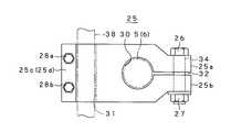
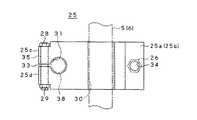
スピーカ装置1は、上述した第1ヘッドレスト軸5或いは第2ヘッドレスト軸6に対して取付部15を介して着脱される。取付部15は、取付部材25と、第1取付ボルト26及び第1ナット27と、一対の第2取付ボルト28a、28b(以下、第2取付ボルト28と総称する。)及び一対の第2ナット29(以下、第2ナット29と総称する。)とを有している。取付部材25は、軽量で機械的強度が大きな合成樹脂材或いはアルミ合金材等によって全体が略矩形板状に形成されており、図5及び図6に示すようにヘッドレスト軸嵌合孔30と、支持アーム取付孔31と、第1スリ割り溝32と、第2スリ割り溝33と、第1ボルト孔34と、一対の第2ボルト孔35a、35b(以下、第2ボルト孔35と総称する。)とが設けられている。  Thespeaker device 1 is attached to and detached from thefirst headrest shaft 5 or thesecond headrest shaft 6 described above via anattachment portion 15. The mountingportion 15 includes a mountingmember 25, a first mountingbolt 26 and afirst nut 27, a pair of second mountingbolts 28a and 28b (hereinafter collectively referred to as a second mounting bolt 28), and a pair of second nuts. 29 (hereinafter collectively referred to as a second nut 29). The mountingmember 25 is made of a synthetic resin material or aluminum alloy material that is lightweight and has high mechanical strength, and is formed in a substantially rectangular plate shape as a whole. As shown in FIGS. 5 and 6, the headrest shaftfitting hole 30, Supportarm mounting hole 31,first slot 32,second slot 33,first bolt hole 34, and a pair of second bolt holes 35a, 35b (hereinafter collectively referred to as second bolt hole 35). )).

ヘッドレスト軸嵌合孔30は、第1ヘッドレスト軸5或いは第2ヘッドレスト軸6の外径とほぼ等しい内径を有し、取付部材25に対して厚み方向に貫通して形成されている。ヘッドレスト軸嵌合孔30には、その一部に全長に亘って取付部材25の側端に開口する第1スリ割り溝32が形成されている。取付部材25は、この第1スリ割り溝32によって区割りされた相対する端部25a、25bを拡げることによって、第1ヘッドレスト軸5又は第2ヘッドレスト軸6を側方からヘッドレスト軸嵌合孔30に嵌合させる。  The headrest shaftfitting hole 30 has an inner diameter substantially equal to the outer diameter of thefirst headrest shaft 5 or thesecond headrest shaft 6, and is formed so as to penetrate the mountingmember 25 in the thickness direction. The headrest shaftfitting hole 30 is formed with afirst slot 32 that opens at a side end of theattachment member 25 over a part of the headrest shaftfitting hole 30. The mountingmember 25 expands theopposite end portions 25a and 25b divided by thefirst slit 32, so that thefirst headrest shaft 5 or thesecond headrest shaft 6 is moved from the side to the headrest shaftfitting hole 30. Fit.

取付部材25には、第1スリ割り溝32に対して直交して連通する第1ボルト孔34が厚み方向に貫通して形成されている。取付部材25は、ヘッドレスト軸嵌合孔30に第1ヘッドレスト軸5或いは第2ヘッドレスト軸6を嵌合させた状態で第1ボルト孔34に第1取付ボルト26が貫通される。取付部材25は、第1取付ボルト26の先端部に第1ナット27がねじ込まれることによって、ヘッドレスト軸嵌合孔30内において第1ヘッドレスト軸5或いは第2ヘッドレスト軸6の外周部を締め付けて固定する。  Theattachment member 25 is formed with afirst bolt hole 34 penetrating in the thickness direction so as to communicate perpendicularly to thefirst slit groove 32. In the mountingmember 25, the first mountingbolt 26 is passed through thefirst bolt hole 34 in a state where thefirst headrest shaft 5 or thesecond headrest shaft 6 is fitted in the headrest shaftfitting hole 30. The mountingmember 25 is fixed by tightening the outer periphery of thefirst headrest shaft 5 or thesecond headrest shaft 6 in the headrest shaftfitting hole 30 by screwing thefirst nut 27 into the tip of the first mountingbolt 26. To do.

取付部材25は、第1ナット27を緩めて第1ボルト孔34から第1取付ボルト26を取り外すことにより、第1ヘッドレスト軸5や第2ヘッドレスト軸6から取り外される。なお、取付部材25は、第1ナット27に例えば蝶ナットを用いることによって、第1ヘッドレスト軸5や第2ヘッドレスト軸6に対して取付け、取外し操作が治具等を用いることなく簡便に行えるようになる。  Theattachment member 25 is detached from thefirst headrest shaft 5 and thesecond headrest shaft 6 by loosening thefirst nut 27 and removing thefirst attachment bolt 26 from thefirst bolt hole 34. Theattachment member 25 is attached to thefirst headrest shaft 5 or thesecond headrest shaft 6 by using, for example, a wing nut as thefirst nut 27, and can be easily removed without using a jig or the like. become.

支持アーム取付孔31は、取付部材25に対してヘッドレスト軸嵌合孔26の貫通方向と直交する厚み方向に貫通して形成されている。支持アーム取付孔31には、その一部に全長に亘って取付部材25の側端に開口する第2スリ割り溝33が形成されている。取付部材25には、この第2スリ割り溝33によって区割りされた相対する端部25c、25dを拡げた状態で後述する支持アーム部16を構成する螺旋管36に設けた連結管部材37aが嵌挿される。  The supportarm attachment hole 31 is formed so as to penetrate theattachment member 25 in the thickness direction orthogonal to the penetration direction of the headrest shaftfitting hole 26. The supportarm mounting hole 31 is formed with asecond slot 33 that partially opens at the side end of the mountingmember 25 over the entire length thereof. Theattachment member 25 is fitted with a connecting pipe member 37a provided on aspiral pipe 36 constituting thesupport arm part 16 described later in a state where the opposite ends 25c and 25d divided by thesecond slit 33 are expanded. Inserted.

取付部材25には、第2スリ割り溝33に対して直交して連通する第2ボルト孔35が上下方向に離間してそれぞれ厚み方向に貫通して形成されている。取付部材25は、支持アーム取付孔31に螺旋管36を嵌挿させた状態で第2ボルト孔35に第2取付ボルト28がそれぞれ貫通される。取付部材25は、第2取付ボルト28の先端部にそれぞれ第2ナット29がねじ込まれることによって、支持アーム取付孔31内において第1ヘッドレスト軸5或いは第2ヘッドレスト軸6の外周部を締め付けて固定する。  Theattachment member 25 is formed with second bolt holes 35 communicating perpendicularly to thesecond slit groove 33 so as to be spaced apart in the vertical direction and penetrate in the thickness direction. In the mountingmember 25, the second mountingbolts 28 are respectively inserted through the second bolt holes 35 in a state where thespiral tube 36 is inserted into the supportarm mounting hole 31. The mountingmember 25 is fixed by tightening the outer periphery of thefirst headrest shaft 5 or thesecond headrest shaft 6 in the supportarm mounting hole 31 by screwing thesecond nut 29 into the tip of the second mountingbolt 28. To do.

取付部材25は、第2ナット29を緩めて第2ボルト孔35から第2取付ボルト28を取り外すことによって、支持アーム部16を取り外すようにする。したがって、取付部材25は、第1ヘッドレスト軸5や第2ヘッドレスト軸6に取り付けた状態のままで、支持アーム部16とスピーカユニット14とを座席3から取り外すことを可能とする。  Theattachment member 25 removes thesupport arm portion 16 by loosening thesecond nut 29 and removing thesecond attachment bolt 28 from thesecond bolt hole 35. Therefore, theattachment member 25 enables thesupport arm portion 16 and thespeaker unit 14 to be detached from theseat 3 while being attached to thefirst headrest shaft 5 and thesecond headrest shaft 6.

なお、取付部25については、上述した構成に限定されるものではなく、第1ヘッドレスト軸5或いは第2ヘッドレスト軸6に対してスピーカ装置1を着脱自在とする適宜の構造であればよい。取付部25は、例えば第1ヘッドレスト軸5や第2ヘッドレスト軸6を挟み込むようにするいわゆる洗濯ばさみのような構造であってもよい。  Note that the mountingportion 25 is not limited to the above-described configuration, and may be any appropriate structure that allows thespeaker device 1 to be detachably attached to thefirst headrest shaft 5 or thesecond headrest shaft 6. Theattachment portion 25 may have a structure such as a so-called clothespin that sandwiches thefirst headrest shaft 5 and thesecond headrest shaft 6, for example.

支持アーム部16は、上述した螺旋管36と、この螺旋管36の両端部36a、36bにそれぞれ一体化された第1連結管部材37及び第2連結管部材38とからなる。螺旋管36は、軽量で機械的強度が大きな合成樹脂材やステンレスやアルミ合金等の金属材により、略波形断面が軸方向に連続して形成された管材からなる。螺旋管36は、周知のように通常の状態では所定の姿勢を自己保持しているが、強い力を加えることにより任意の位置でかつ任意の角度に湾曲されるとともに、この湾曲状態が保持される可撓性を有する。  Thesupport arm portion 16 includes the above-describedspiral tube 36, and a firstconnection tube member 37 and a secondconnection tube member 38 that are integrated with bothend portions 36a and 36b of thespiral tube 36, respectively. Thespiral tube 36 is made of a tube material having a substantially corrugated cross-section formed continuously in the axial direction by a synthetic resin material that is lightweight and has high mechanical strength, or a metal material such as stainless steel or aluminum alloy. As is well known, thespiral tube 36 self-holds a predetermined posture in a normal state. However, by applying a strong force, thespiral tube 36 is bent at an arbitrary position and at an arbitrary angle, and this curved state is maintained. Flexible.

螺旋管36は、上述した特性によってスピーカユニット14を取付部15との間で所定の姿勢に保持するとともに、このスピーカユニット14を任意の角度や位置に向けることを可能とする。螺旋管36は、スピーカユニット14から再生信号供給コード18aを引き出して座席3まで空中をブラブラさせずにガイドする。なお、螺旋管36は、図示しないが外周部に樹脂シート等からなるブレードを被着することによって、全長の長さ変化を規制するとともにほこり等の付着を防止し或いは搭乗者が頭等をぶっけた場合の保護等を図るようにする。  Thespiral tube 36 holds thespeaker unit 14 in a predetermined posture with the mountingportion 15 according to the characteristics described above, and enables thespeaker unit 14 to be directed to an arbitrary angle or position. Thespiral tube 36 pulls the reproduction signal supply cord 18a from thespeaker unit 14 and guides it up to theseat 3 without tumbling the air. Although not shown, thespiral tube 36 is attached with a blade made of a resin sheet or the like on the outer periphery, thereby restricting a change in length of the entire length and preventing adhesion of dust or the like. Try to protect against damage.

第1連結管部材37は、上述したスピーカユニット14のハウジング12に設けたブッシュ23の軸孔とほぼ同径に形成されるとともに、詳細を省略するが外周部にねじが形成されている。第1連結管部材37は、一端側を螺旋管36の一端部36aに結合されるとともに外周ねじ部を形成した他端側がブッシュ23を貫通してハウジング12内に挿通される。第1連結管部材37は、ハウジング12内に形成した取付部に対して外周ねじ部がねじ止めされて固定される。第1連結管部材37には、スピーカ13に接続した再生信号供給コード18aが挿通され、螺旋管36内に導かれる。  The first connectingpipe member 37 is formed to have substantially the same diameter as the shaft hole of thebush 23 provided in thehousing 12 of thespeaker unit 14 described above, and a screw is formed on the outer peripheral portion although the details are omitted. The first connectingpipe member 37 has one end coupled to the one end 36 a of thehelical tube 36 and the other end formed with the outer threaded portion passing through thebush 23 and inserted into thehousing 12. The first connectingpipe member 37 is fixed by fixing an outer peripheral screw portion to an attachment portion formed in thehousing 12. A reproduction signal supply cord 18 a connected to thespeaker 13 is inserted into the firstconnection pipe member 37 and guided into thespiral pipe 36.

第2連結管部材38は、上述した取付部材25の支持アーム取付孔31の軸孔とほぼ同径に形成されており、一端側が螺旋管36の一端部36aに結合される。第2連結管部材38は、支持アーム取付孔31に貫通され、上述したように第2取付ボルト28に対して第2ナット29を締め付けることによって取付部材25に固定される。第2連結管部材38からは、螺旋管36を挿通された再生信号入力コード18bが引き出される。  The second connectingpipe member 38 is formed to have substantially the same diameter as the shaft hole of the supportarm mounting hole 31 of the mountingmember 25 described above, and one end side thereof is coupled to one end portion 36 a of thehelical tube 36. The second connectingpipe member 38 passes through the supportarm mounting hole 31 and is fixed to the mountingmember 25 by tightening thesecond nut 29 against the second mountingbolt 28 as described above. From the second connectingpipe member 38, the reproductionsignal input cord 18b inserted through thespiral pipe 36 is drawn out.

以上のように構成されたスピーカ装置1においては、図2に示すように座席3からヘッドレスト4をやや引き上げることによって露出された第1ヘッドレスト軸5に第1ユニット10Rが取り付けられるとともに、第2ヘッドレスト軸6に対して第2ユニット10Lが取り付けられる。スピーカ装置1においては、各ユニット10が取付部15を第1ヘッドレスト軸5或いは第2ヘッドレスト軸6に固定され、入力部11が自動車2に搭載された適宜の音源と接続される。スピーカ装置1においては、支持アーム部16が座席3に座った搭乗者Mに合わせて途中箇所を適宜に湾曲操作されることによって、スピーカユニット14の放音開口部24を座席3に座った搭乗者Mの耳元に対向されるようにする。  In thespeaker device 1 configured as described above, thefirst unit 10R is attached to thefirst headrest shaft 5 exposed by slightly lifting theheadrest 4 from theseat 3 as shown in FIG. Thesecond unit 10 </ b> L is attached to theshaft 6. In thespeaker device 1, eachunit 10 has theattachment portion 15 fixed to thefirst headrest shaft 5 or thesecond headrest shaft 6, and theinput portion 11 is connected to an appropriate sound source mounted on theautomobile 2. In thespeaker device 1, thesupport arm portion 16 is appropriately bent at an intermediate position according to the passenger M sitting on theseat 3, so that thesound emission opening 24 of thespeaker unit 14 is seated on theseat 3. It faces the ear of the person M.

スピーカ装置1においては、第1ヘッドレスト軸5或いは第2ヘッドレスト軸6を取付部材25のヘッドレスト軸嵌合孔30内に嵌合し、第1ボルト孔34に挿通した第1取付ボルト26に対して第1ナット27をねじ込んで締め付けることにより、取付部材25が第1ヘッドレスト軸5或いは第2ヘッドレスト軸6に固定される。スピーカ装置1においては、座席3に対してヘッドレスト4を押し付けることにより、これら座席3とヘッドレスト4との間に取付部15が隠される。  In thespeaker device 1, thefirst headrest shaft 5 or thesecond headrest shaft 6 is fitted into the headrest shaftfitting hole 30 of the mountingmember 25, and the first mountingbolt 26 inserted through thefirst bolt hole 34 is used. The mountingmember 25 is fixed to thefirst headrest shaft 5 or thesecond headrest shaft 6 by screwing and tightening thefirst nut 27. In thespeaker device 1, the mountingportion 15 is hidden between theseat 3 and theheadrest 4 by pressing theheadrest 4 against theseat 3.

スピーカ装置1においては、取付部材25の支持アーム取付孔31に支持アーム部16の第2連結管部材38が嵌挿される。スピーカ装置1においては、第2ボルト孔35に挿通した第2取付ボルト28に第2ナット29をねじ込んで締め付けることにより、取付部15に対して支持アーム部16が一体化される。スピーカ装置1においては、支持アーム部16に対してスピーカユニット14が一体化されている。  In thespeaker device 1, the second connectingpipe member 38 of thesupport arm portion 16 is fitted into the supportarm mounting hole 31 of the mountingmember 25. In thespeaker device 1, thesupport arm portion 16 is integrated with the mountingportion 15 by screwing and tightening thesecond nut 29 into the second mountingbolt 28 inserted through thesecond bolt hole 35. In thespeaker device 1, thespeaker unit 14 is integrated with thesupport arm portion 16.

スピーカ装置1においては、第2連結管部材38から引き出した再生信号入力コード18bを邪魔にならないようにして車内に導き、入力部11のケース17を結合部を介して適当な箇所に固定する。スピーカ装置1においては、入力部11のピンプラグ20が適宜の音源の出力ジャックと接続されることにより、音源から出力される再生信号が再生信号供給コード18aと再生信号入力コード18bを介してスピーカユニット14へと供給される。  In thespeaker device 1, the reproductionsignal input cord 18 b pulled out from the second connectingpipe member 38 is guided into the vehicle without getting in the way, and thecase 17 of theinput unit 11 is fixed to an appropriate location via the coupling unit. In thespeaker device 1, thepin plug 20 of theinput unit 11 is connected to an output jack of an appropriate sound source, so that a reproduction signal output from the sound source is transmitted to the speaker unit via the reproduction signal supply code 18 a and the reproductionsignal input code 18 b. 14 is supplied.

スピーカ装置1においては、座席3に座った搭乗者Mによって、耳元の近くにスピーカユニット14が位置するように支持アーム部16の調整操作が行われる。スピーカ装置1においては、上述したように支持アーム部16に螺旋管36を用いたことにより途中箇所を適宜に湾曲させたり向きを変えたりすることが可能であり、図7に示すようにスピーカユニット14が搭乗者Mの耳元に対向される。スピーカ装置1においては、この場合に、前方を向いた搭乗者Mの耳元に対して、スピーカユニット14の放音開口部24が対向するように支持アーム部16の湾曲状態が調整される。  In thespeaker device 1, an adjustment operation of thesupport arm unit 16 is performed by the passenger M sitting on theseat 3 so that thespeaker unit 14 is positioned near the ear. In thespeaker device 1, as described above, by using thespiral tube 36 for thesupport arm portion 16, it is possible to appropriately curve or change the direction of the midway portion, as shown in FIG. 7. 14 faces the passenger's M ear. In thespeaker device 1, in this case, the bending state of thesupport arm portion 16 is adjusted so that thesound emission opening 24 of thespeaker unit 14 faces the ear of the passenger M facing forward.

スピーカ装置1においては、図7に示すように座席3に座る搭乗者が大人MMである場合には、頭部がヘッドレスト4の位置にあるために支持アーム部16の螺旋管36を曲げる調整量も少ない。一方、スピーカ装置1においては、図8に示すように座席3に座る搭乗者が子供MSである場合には、頭部がヘッドレスト4まで届かないことがある。スピーカ装置1においては、同図に示すように支持アーム部16の螺旋管36を下方側へと大きく曲げることによって、この子供MSの耳元にスピーカユニット14を対向させることが可能となる。したがって、スピーカ装置1においては、大人MMから供MSまでが互換性を有して使用することが可能である。  In thespeaker device 1, when the occupant sitting on theseat 3 is an adult MM as shown in FIG. 7, the adjustment amount for bending thespiral tube 36 of thesupport arm portion 16 because the head is at the position of theheadrest 4. There are few. On the other hand, in thespeaker device 1, when the passenger sitting on theseat 3 is a child MS as shown in FIG. 8, the head may not reach theheadrest 4. In thespeaker device 1, thespeaker unit 14 can be made to face the ear of the child MS by largely bending thespiral tube 36 of thesupport arm portion 16 downward as shown in FIG. Therefore, in thespeaker device 1, the adult MM to the serving MS can be used interchangeably.

スピーカ装置1においては、音源から出力された再生信号が入力部11から支持アーム部16内を導通されたコード18を介してスピーカユニット14に供給されると、この再生信号に基づく再生音がスピーカ13によって再生されて放音部13aから放音される。スピーカ装置1においては、上述したようにスピーカユニット14が、スピーカ13の放音部13aに対して面方向及び直径方向に対して傾斜するとともに放音開口部24に向かって次第に開口径を大きくさせる傾斜を付してハウジング12に設けられたメインリフレクタ21を有している。スピーカ装置1においては、放音部13aから放音される再生音が、メインリフレクタ21に反射されて放音開口部24を介して搭乗者Mの耳元に向かって放音されるようになる。  In thespeaker device 1, when the reproduction signal output from the sound source is supplied from theinput unit 11 to thespeaker unit 14 via thecord 18 that is conducted through thesupport arm unit 16, the reproduction sound based on the reproduction signal is transmitted to the speaker. 13, and is emitted from the sound emitting unit 13 a. In thespeaker device 1, as described above, thespeaker unit 14 is inclined with respect to the sound emitting part 13 a of thespeaker 13 with respect to the surface direction and the diameter direction and gradually increases in opening diameter toward thesound emitting opening 24. Themain reflector 21 is provided on thehousing 12 with an inclination. In thespeaker device 1, the reproduction sound emitted from the sound emission unit 13 a is reflected by themain reflector 21 and emitted toward the ear of the passenger M through thesound emission opening 24.

スピーカ装置1においては、上述したようにスピーカユニット14が、ハウジング12の開口部12aとメインリフレクタ21との間に外周部の一部を構成して介在する円弧状のサイドリフレクタ22を有してなる。スピーカ装置1においては、サイドリフレクタ22が、スピーカ13から放音されてメインリフレクタ21によって反射される再生音の周辺への音漏れを抑制して搭乗者Mに向かって所定の音圧を保持して効率的に放音されるようにする。  In thespeaker device 1, as described above, thespeaker unit 14 has the arc-shapedside reflector 22 interposed between the opening 12 a of thehousing 12 and themain reflector 21 so as to constitute a part of the outer peripheral portion. Become. In thespeaker device 1, theside reflector 22 suppresses sound leakage around the reproduced sound emitted from thespeaker 13 and reflected by themain reflector 21, and maintains a predetermined sound pressure toward the passenger M. So that the sound is emitted efficiently.

スピーカ装置1においては、各座席3に対して簡易な後付け操作によって設置されることから、各搭乗者Mがそれぞれ個別に選択した音源からの再生信号に基づく再生音を視聴することを可能とする。スピーカ装置1においては、簡易な操作によって各搭乗者Mの耳元にスピーカユニット14が対向されることから、最適な状態で再生音を視聴することを可能とするとともに相互の音漏れによる干渉も抑制される。スピーカ装置1においては、搭乗者Mの体型の差異に対する互換性も極めて高く、小さな子供でも使用することが可能である。スピーカ装置1においては、乗降等に際して搭乗者Mがスピーカユニット14にぶっかることがあっても支持アーム部16が変形することによってその衝撃を吸収することで、取付部15の破損や断線等の発生を低減しまた搭乗者Mの安全を確保する。  Since thespeaker device 1 is installed on eachseat 3 by a simple retrofitting operation, each passenger M can view the reproduction sound based on the reproduction signal from the sound source individually selected. . In thespeaker device 1, thespeaker unit 14 is opposed to each passenger M's ear by a simple operation, so that it is possible to view the reproduced sound in an optimum state and to suppress interference due to mutual sound leakage. Is done. Thespeaker device 1 has extremely high compatibility with the difference in the body shape of the passenger M, and can be used even by a small child. In thespeaker device 1, even if the occupant M hits thespeaker unit 14 during getting on and off, thesupport arm portion 16 is deformed to absorb the impact, thereby causing damage to the mountingportion 15 or disconnection. The occurrence is reduced and the safety of the passenger M is ensured.

ところで、スピーカ装置1においては、上述したようにスピーカユニット14が、ハウジング12の開口部12aにサイドリフレクタ22を介してメインリフレクタ21が固定状態で取り付けられてなる。また、スピーカ装置1においては、第1ヘッドレスト軸5や第2ヘッドレスト軸6に対して取付部15が着脱自在とされるとともに、この取付部15に対してスピーカユニット14を設けた支持アーム部16が着脱自在とされるように構成されてなる。  By the way, in thespeaker device 1, as described above, thespeaker unit 14 is attached to the opening 12 a of thehousing 12 with themain reflector 21 being fixed via theside reflector 22. In thespeaker device 1, theattachment portion 15 is detachable with respect to thefirst headrest shaft 5 and thesecond headrest shaft 6, and thesupport arm portion 16 is provided with thespeaker unit 14 with respect to theattachment portion 15. Is configured to be detachable.

スピーカ装置1においては、未使用状態においてハウジング12から飛び出したメインリフレクタ21が邪魔になることがある。また、スピーカ装置1においては、ある座席3に取り付けたままで使用するためにさほど簡易な操作によって着脱を行う必要は無く、むしろ取付部15をより簡易に構成することも考慮される。  In thespeaker device 1, themain reflector 21 that protrudes from thehousing 12 in an unused state may get in the way. Further, in thespeaker device 1, it is not necessary to attach and detach with a very simple operation in order to use it while being attached to acertain seat 3, but it is also considered that theattachment portion 15 is configured more simply.

図9に第2の実施の形態として示したスピーカ装置40は、スピーカ装置1と基本的な構成を同等として、上述した改良点や要望点について対応を図ったものである。スピーカ装置40は、同図に示すように筒状の取付部材42とセットボルト43とからなる簡易なな構造の取付部41と、ハウジング45に対してサイドリフレクタ47を介してメインリフレクタ46を開閉自在としたスピーカユニット44とを有してなる。なお、スピーカ装置40は、上述したスピーカ装置1と同等の部位については同一符号を付すことによって詳細な説明を省略する。  Thespeaker device 40 shown as the second embodiment in FIG. 9 has the same basic configuration as that of thespeaker device 1 and addresses the above-described improvements and demands. Thespeaker device 40 opens and closes themain reflector 46 with respect to thehousing 45 and thehousing 45 via theside reflector 47 and asimple attachment portion 41 comprising acylindrical attachment member 42 and aset bolt 43 as shown in FIG. And afree speaker unit 44. In thespeaker device 40, the same parts as those of the above-describedspeaker device 1 are denoted by the same reference numerals, and detailed description thereof is omitted.

第1ヘッドレスト軸5及び第2ヘッドレスト軸6は、座席3のガイド部から引き抜くことによってヘッドレスト4を取り外すことを可能とする。スピーカ装置40は、座席3から引き抜いた第1ヘッドレスト軸5或いは第2ヘッドレスト軸6に対して取付部41を取り付けた後にこれら第1ヘッドレスト軸5と第2ヘッドレスト軸6とが再びガイド部内に差し込まれることによって座席3に設置される。  Thefirst headrest shaft 5 and thesecond headrest shaft 6 can be detached from theheadrest 4 by being pulled out from the guide portion of theseat 3. In thespeaker device 40, after theattachment portion 41 is attached to thefirst headrest shaft 5 or thesecond headrest shaft 6 pulled out from theseat 3, thefirst headrest shaft 5 and thesecond headrest shaft 6 are again inserted into the guide portion. Installed in theseat 3.

取付部材42は、合成樹脂材や金属材によって筒状に形成され、第1ヘッドレスト軸5や第2ヘッドレスト軸6の軸径とほぼ同径の取付孔42aを有している。取付部材42には、外周部に取付孔42aに貫通するねじ孔を有するボス部42bが形成されている。取付部材42は、座席3から抜き取られた第1ヘッドレスト軸5或いは第2ヘッドレスト軸6をその先端から取付孔42aに嵌挿することによって組み合わされる。なお、取付部材42には、外周部に支持アーム部16を構成する螺旋管36の一端部が固定される。  Theattachment member 42 is formed in a cylindrical shape from a synthetic resin material or a metal material, and has an attachment hole 42 a having substantially the same diameter as the shaft diameters of thefirst headrest shaft 5 and thesecond headrest shaft 6. Theattachment member 42 is formed with aboss portion 42b having a screw hole penetrating the attachment hole 42a on the outer peripheral portion. Theattachment member 42 is combined by fitting thefirst headrest shaft 5 or thesecond headrest shaft 6 extracted from theseat 3 into the attachment hole 42a from the tip thereof. Note that one end portion of thespiral tube 36 constituting thesupport arm portion 16 is fixed to the mountingmember 42 on the outer peripheral portion.

取付部材42には、取付孔42aに第1ヘッドレスト軸5或いは第2ヘッドレスト軸6を嵌挿させた状態でボス部42bのねじ孔にセットボルト43のねじ部がねじ込まれる。セットボルト43は、ねじ込まれるにしたがって先端部が第1ヘッドレスト軸5或いは第2ヘッドレスト軸6の外周部に突き当たることによって、これら第1ヘッドレスト軸5或いは第2ヘッドレスト軸6に対して取付部材42を固定する。なお、取付部材42は、その外周部に螺旋管36の基端部を直接固定することから再生信号供給コード18aのガイド構造を有していない。したがって、再生信号供給コード18aは、螺旋管36の外周部に設けられた引出し孔から外部へと引き出される。  In the mountingmember 42, the screw portion of theset bolt 43 is screwed into the screw hole of theboss portion 42 b in a state where thefirst headrest shaft 5 or thesecond headrest shaft 6 is fitted into the mounting hole 42 a. As theset bolt 43 is screwed, the tip part abuts against the outer periphery of thefirst headrest shaft 5 or thesecond headrest shaft 6, so that theattachment member 42 is attached to thefirst headrest shaft 5 or thesecond headrest shaft 6. Fix it. Theattachment member 42 does not have a guide structure for the reproduction signal supply cord 18a because the proximal end portion of thespiral tube 36 is directly fixed to the outer peripheral portion thereof. Therefore, the reproduction signal supply cord 18a is drawn out from the drawing hole provided in the outer peripheral portion of thespiral tube 36.

スピーカユニット44も、図10乃至図12に示すようにハウジング45が、合成樹脂材により一方側面部を開口した全体略カップ状に成形されており、内部にスピーカ13を取り付けるための高さ方向の取付孔を有する複数の取付ボス部48が一体に形成されている。ハウジング45には、外周部に形成された取付孔に第1連結管部材37が固定され、この第1連結管部材37を介してスピーカ13と接続された再生信号供給コード18aが引き出されている。  As shown in FIGS. 10 to 12, thespeaker unit 44 also has ahousing 45 that is formed in a generally cup shape with one side portion opened by a synthetic resin material, and has a height direction for mounting thespeaker 13 therein. A plurality of mountingboss portions 48 having mounting holes are integrally formed. In thehousing 45, a first connectingpipe member 37 is fixed to a mounting hole formed in an outer peripheral portion, and a reproduction signal supply cord 18a connected to thespeaker 13 is drawn through the first connectingpipe member 37. .

ハウジング45には、図13に示すように外周部がやや厚みを大きくして形成されており、開口部45aの内周縁に全周に亘って段部49が形成されている。段部49は、メインリフレクタ46の厚みとほぼ等しい高さを有するとともに、メインリフレクタ46の外径とほぼ等しい内径を有して形成されている。ハウジング45には、開口部45aの内周縁に詳細を後述するようにメインリフレクタ46を開閉自在に組み合わせるためのヒンジ凹部50が形成されている。ヒンジ凹部50には、相対する側面に軸孔50a、50bが形成されている。ハウジング45には、開口部45aの内周縁にヒンジ凹部50と対向して段部49に突出するストッパ凸部51が形成されている。  As shown in FIG. 13, thehousing 45 has an outer peripheral portion with a slightly increased thickness, and a steppedportion 49 is formed on the inner peripheral edge of the opening 45a over the entire periphery. Thestep portion 49 has a height substantially equal to the thickness of themain reflector 46 and has an inner diameter substantially equal to the outer diameter of themain reflector 46. Thehousing 45 is formed with ahinge recess 50 for assembling themain reflector 46 in an openable and closable manner on the inner periphery of the opening 45a as will be described in detail later. Thehinge recess 50 is formed withshaft holes 50a and 50b on opposite side surfaces. Thehousing 45 is formed with a stopperconvex portion 51 that protrudes to the steppedportion 49 so as to face the hingeconcave portion 50 on the inner peripheral edge of the opening 45a.

ハウジング45には、開口部45aに開口して高さ方向のガイドスリット52が形成されている。ガイドスリット52は、ヒンジ凹部50と対向する位置を中心として開口部45aの円周方向の長さに対して略1/2円周長を有する円弧状のスリットであり、詳細を後述するようにサイドリフレクタ47が出入りする。ガイドスリット52は、サイドリフレクタ47の長さと厚みとほぼ等しい長さと開口幅に形成されている。  In thehousing 45, a guide slit 52 in the height direction is formed so as to open to the opening 45a. The guide slit 52 is an arc-shaped slit having a substantially 1/2 circumferential length with respect to the circumferential length of the opening 45a with the position facing thehinge recess 50 as the center, as will be described in detail later. Theside reflector 47 enters and exits. The guide slit 52 is formed to have a length and an opening width substantially equal to the length and thickness of theside reflector 47.

なお、ハウジング45は、上述したように開口部45aに段部49やヒンジ凹部50或いはストッパ凸部51やガイドスリット52が形成されたやや複雑となり、例えば外周部の肉厚を規制すると内周側に庇状に突出する部位も生じる。したがって、ハウジング45は、例えばカップ状の本体部と、上述した部位を形成したプレート体とを組み合わせて構成するようにしてもよい。  As described above, thehousing 45 is somewhat complicated in that thestep portion 49, thehinge recess 50, thestopper projection 51, and the guide slit 52 are formed in the opening 45a. The part which protrudes in a bowl shape also arises. Therefore, thehousing 45 may be configured by combining, for example, a cup-shaped main body portion and a plate body in which the above-described portion is formed.

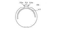
メインリフレクタ46も、合成樹脂材等によってハウジング45の段部49の高さと内径とほぼ等しい厚みと外径とを有する略円盤状に形成されてなる。メインリフレクタ46は、図14に示すようにハウジング45のヒンジ凹部49と対向する外周部位にヒンジ凸部53が一体に形成されている。ヒンジ凸部53は、その幅がヒンジ凹部50の幅とほぼ等しく形成されており、その両側面にヒンジ凹部50側の軸孔50a、50bに対向して軸部53a、53bが一体に突出形成されている。なお、メインリフレクタ46は、ハウジング45の開口部45aを開放した状態において、上述したスピーカ装置1のメインリフレクタ21とその作用を同様とすることから説明を省略する。  Themain reflector 46 is also formed in a substantially disc shape having a thickness and an outer diameter substantially equal to the height and inner diameter of the steppedportion 49 of thehousing 45 by a synthetic resin material or the like. As shown in FIG. 14, themain reflector 46 is integrally formed with a hingeconvex portion 53 at an outer peripheral portion facing the hingeconcave portion 49 of thehousing 45. Thehinge protrusion 53 is formed so that the width thereof is substantially equal to the width of thehinge recess 50, and theshaft parts 53a and 53b are integrally formed on both side surfaces so as to face the shaft holes 50a and 50b on thehinge recess 50 side. Has been. Themain reflector 46 has the same function as that of themain reflector 21 of thespeaker device 1 described above in a state in which the opening 45a of thehousing 45 is opened, and thus the description thereof is omitted.

メインリフレクタ46は、ヒンジ凸部53をヒンジ凹部50内に組み合わせるとともに軸部53a、53bを相対する軸孔50a、50bに嵌合させることによって、ハウジング45に対してその開口部45aを開閉するようにして組み合わされる。メインリフレクタ46は、例えば軸部53a、53bにトーションスプリング54を組み付けることによって、ハウジング45から開く方向の回動習性が付与される。なお、メインリフレクタ46は、トーションスプリング54に代えて例えば板ばね等の弾性手段によってかかる回動習性が付与されるようにしてもよい。  Themain reflector 46 is configured to open and close the opening 45a with respect to thehousing 45 by combining the hingeconvex portion 53 in the hingeconcave portion 50 and fitting theshaft portions 53a and 53b into theopposite shaft holes 50a and 50b. Combined. Themain reflector 46 is imparted with a turning habit in the direction of opening from thehousing 45 by assembling thetorsion spring 54 to theshaft portions 53a and 53b, for example. Themain reflector 46 may be provided with such a turning behavior by an elastic means such as a leaf spring instead of thetorsion spring 54.

メインリフレクタ46は、ハウジング45の開口部45aを閉じた状態においてヒンジ凸部53と対向する外周縁がストッパ凸部51によって係止されてハウジング45の蓋体を構成する。メインリフレクタ46は、図12に示すように段部49内に収納されて凹凸の無いハウジング45を構成し、引っ掛かり等による破損が防止される。  Themain reflector 46 constitutes a cover body of thehousing 45 with the outer peripheral edge facing the hingeconvex portion 53 being locked by the stopperconvex portion 51 when the opening 45 a of thehousing 45 is closed. As shown in FIG. 12, themain reflector 46 is housed in a steppedportion 49 to form ahousing 45 having no unevenness, and is prevented from being damaged due to catching or the like.

メインリフレクタ46は、ストッパ凸部51による係止状態を解除されることにより、トーションスプリング54の弾性力によって回動して図11に示すように開口部45aを開放する。メインリフレクタ46は、ストッパ構造によってハウジング45に対して所定角度で開いた状態で回動動作が停止されて開口部45aとの間に放音開口部55を構成する。また、メインリフレクタ46は、例えばハウジング45との間に図示しないロック構造が設けられており、ストッパ構造によって規定された所定角度に開いた状態で固定される。なお、放音開口部55は、上述したスピーカ装置1の放音開口部24と同等に構成される。  Themain reflector 46 is rotated by the elastic force of thetorsion spring 54 to release the opening 45a as shown in FIG. Themain reflector 46 is rotated at a predetermined angle with respect to thehousing 45 by the stopper structure, and the rotation operation is stopped to form asound emitting opening 55 between the opening 45a. Further, themain reflector 46 is provided with a lock structure (not shown) between, for example, thehousing 45 and is fixed in a state of being opened at a predetermined angle defined by the stopper structure. Thesound emission opening 55 is configured in the same manner as thesound emission opening 24 of thespeaker device 1 described above.

ストッパ構造については、詳細を省略するが例えばヒンジ凸部53とストッパ凸部51とに形成した角度規制構造や、後述するサイドリフレクタ47とガイドスリット51とに形成した角度規制構造によって構成される。なお、メインリフレクタ46は、例えばヒンジ凸部53を筒状に形成してハウジング45側のヒンジ凹部50の軸孔50a、50bとに支軸を挿通してハウジング45に対して回動自在に支持されるように構成してもよい。  The details of the stopper structure are omitted. For example, the stopper structure includes an angle restricting structure formed on the hingeconvex portion 53 and the stopperconvex portion 51, and an angle restricting structure formed on theside reflector 47 and the guide slit 51 described later. For example, themain reflector 46 is formed to have ahinge projection 53 in a cylindrical shape, and is inserted into the shaft holes 50 a and 50 b of thehinge recess 50 on thehousing 45 side so as to be rotatable with respect to thehousing 45. You may comprise.

メインリフレクタ46には、図10及び図14に示すように内面にサイドリフレクタ47が一体に突出形成されている。サイドリフレクタ47は、ヒンジ凸部53と対向する位置を中心としてメインリフレクタ46の円周方向の長さに対して略1/2円周長を有する円弧状の凸部からなり、上述したようにハウジング45に形成したガイドスリット52の長さと開口幅とほぼ等しい長さと厚みを以って形成されている。なお、サイドリフレクタ47は、その作用を上述したスピーカ装置1のサイドリフレクタ22と同様とすることから説明を省略する。  As shown in FIGS. 10 and 14, aside reflector 47 is integrally formed on the inner surface of themain reflector 46. Theside reflector 47 is formed of an arc-shaped convex portion having a circumferential length of approximately ½ with respect to the circumferential length of themain reflector 46 with the position facing the hingeconvex portion 53 as the center, as described above. The guide slit 52 formed in thehousing 45 is formed with a length and thickness substantially equal to the opening width. Theside reflector 47 is the same as theside reflector 22 of thespeaker device 1 described above, so that the description thereof is omitted.

サイドリフレクタ47は、メインリフレクタ46がハウジング45に組み合わされる際に、全長に亘ってガイドスリット52内に嵌合される。サイドリフレクタ47は、メインリフレクタ46がハウジング45に対して所定の角度を以って回動されて開口部45aを開放した状態でも、図11に示すようにその下端部位が全長に亘ってガイドスリット52内に嵌合した状態を保持される高さを有している。  Theside reflector 47 is fitted into the guide slit 52 over the entire length when themain reflector 46 is assembled to thehousing 45. Even when themain reflector 46 is rotated at a predetermined angle with respect to thehousing 45 to open the opening 45a, theside reflector 47 has its lower end portion extending over the entire length as shown in FIG. 52 has a height that can be held in a state of being fitted in the inside.

サイドリフレクタ47については、上述したスピーカ装置1のサイドリフレクタ22と同様に、メインリフレクタ46をハウジング45の開口部45aに対して面方向及び直径方向に対して傾斜させるとともに放音開口部55に向かって次第に開口形状を大きくするような傾斜を付すようにしてメインリフレクタ46に一体に形成されている。サイドリフレクタ47は、詳細には図14に示すようにヒンジ凸部53に対して高さが大きい部位側をやや長くするようにして形成されている。なお、サイドリフレクタ47は、例えば下端縁に折曲部を形成し、メインリフレクタ46が回動した際にガイドスリットの下端部と衝合することによって上述した角度調整構造を構成するようにしてもよい。  As for theside reflector 47, like theside reflector 22 of thespeaker device 1 described above, themain reflector 46 is inclined with respect to the opening 45 a of thehousing 45 with respect to the surface direction and the diameter direction and directed toward thesound emission opening 55. Thus, themain reflector 46 is integrally formed so as to be inclined so as to gradually increase the opening shape. Specifically, as shown in FIG. 14, theside reflector 47 is formed so as to be slightly longer on the side of the portion where the height is larger than the hingeconvex portion 53. For example, theside reflector 47 forms a bent portion at the lower end edge, and when themain reflector 46 rotates, theside reflector 47 makes contact with the lower end portion of the guide slit to constitute the angle adjusting structure described above. Good.

なお、スピーカユニット44は、上述した構造によってハウジング45に対してメインリフレクタ46を回動自在に組み合わせるように構成したが、かかる構造に限定されるものでは無いことは勿論である。スピーカユニット44は、例えばハウジング45の外周部に一体に突出形成したヒンジ部を介してメインリフレクタ46を回動自在に組み合わせるようにしてもよい。また、スピーカユニット44は、ハウジング45とサイドリフレクタ47とにヒンジ構造を設けて、サイドリフレクタ47を介してメインリフレクタ46にハウジング45を回動自在に組み合わせるようにしてもよい。  In addition, although thespeaker unit 44 is configured to rotatably combine themain reflector 46 with respect to thehousing 45 by the above-described structure, it is needless to say that thespeaker unit 44 is not limited to such a structure. For example, thespeaker unit 44 may be rotatably combined with themain reflector 46 via a hinge portion integrally formed on the outer peripheral portion of thehousing 45. Further, thespeaker unit 44 may be provided with a hinge structure in thehousing 45 and theside reflector 47 so that thehousing 45 is rotatably combined with themain reflector 46 via theside reflector 47.

スピーカ装置40においては、上述したようにスピーカユニット44が、ハウジング45に対してメインリフレクタ46を回動自在に組み合わせてなる。スピーカ装置40においては、ハウジング45に対して所定の開き角度を以って組み合わされるメインリフレクタ46が放音開口部55を構成して座席3に座った搭乗者Mに対して良好な状態で適宜の音源から出力された再生信号に基づく再生音を放音する。  In thespeaker device 40, as described above, thespeaker unit 44 is configured by combining themain reflector 46 with thehousing 45 so as to be rotatable. In thespeaker device 40, themain reflector 46 combined with a predetermined opening angle with respect to thehousing 45 constitutes asound emission opening 55 and is appropriately in a good condition for the passenger M sitting on theseat 3. Plays a playback sound based on the playback signal output from the sound source.

スピーカ装置40においては、未使用時にハウジング45から突出するメインリフレクタ46が邪魔となる場合に、このメインリフレクタ46をハウジング45内に収納する。スピーカ装置40においては、ロック構造を解除してメインリフレクタ46がトーションスプリング54の弾性力に抗してハウジング45側へと押し込まれる。スピーカ装置40においては、メインリフレクタ46が段部49内に収納されるとともに外周縁をストッパ凸部51によって係止される。  In thespeaker device 40, when themain reflector 46 protruding from thehousing 45 becomes an obstacle when not in use, themain reflector 46 is accommodated in thehousing 45. In thespeaker device 40, the lock structure is released and themain reflector 46 is pushed toward thehousing 45 against the elastic force of thetorsion spring 54. In thespeaker device 40, themain reflector 46 is housed in the steppedportion 49 and the outer peripheral edge is locked by the stopperconvex portion 51.

ところで、スピーカ装置40においては、スピーカ装置1と同様に、スピーカユニット44がスピーカ13の放音部13aを正面に向けることで投影面積を小さくして搭乗者Mのサイド視界を確保するようにして使用される。スピーカ装置40においては、メインリフレクタ46やサイドリフレクタ47によってスピーカ13から放音される再生音を放音開口部55側へと反射させ、スピーカ13の放音部13aと搭乗者Mの両耳との軸線のズレを補正して音圧レベル特性が保持されるようにしている。  By the way, in thespeaker device 40, like thespeaker device 1, thespeaker unit 44 directs the sound emitting part 13 a of thespeaker 13 to the front so as to reduce the projection area and secure the side view of the passenger M. used. In thespeaker device 40, the reproduction sound emitted from thespeaker 13 by themain reflector 46 and theside reflector 47 is reflected to thesound emission opening 55 side, and the sound emission part 13 a of thespeaker 13 and both ears of the passenger M The sound pressure level characteristic is maintained by correcting the deviation of the axis.

スピーカ装置40においては、放音開口部55と搭乗者Mの両耳との軸線のズレをより小さくしようとした場合に、ハウジング45に対するメインリフレクタ46の開き角度をある程度大きく設定する必要がある。スピーカ装置40においては、このためにスピーカユニット44の投影面積の低減にも限界があり搭乗者Mのサイド視界特性を低下させるとともに、ハウジング45に対するメインリフレクタ46やサイドリフレクタ47の機械的結合強度も低下する。また、スピーカ装置40においては、放音開口部55の開口寸法が大きくなって再生音の指向性が低下する。  In thespeaker device 40, it is necessary to set the opening angle of themain reflector 46 with respect to thehousing 45 to a certain degree when the axial deviation between thesound emitting opening 55 and both ears of the passenger M is to be made smaller. For this reason, thespeaker device 40 has a limit in reducing the projected area of thespeaker unit 44, which reduces the side visibility characteristics of the passenger M, and the mechanical coupling strength of themain reflector 46 and theside reflector 47 with respect to thehousing 45. descend. Further, in thespeaker device 40, the opening size of thesound emission opening 55 is increased, and the directivity of the reproduced sound is lowered.

スピーカ装置40においては、メインリフレクタ46の開き角度を小さくした場合に、このメインリフレクタ46によって反射されて放音開口部55側へと導かれる再生音の方向がハウジング45側に近くなる。したがって、スピーカ装置40においては、再生音の一部がハウジング45のヒンジ部と対向する開口部45aの周壁に当たり、ハウジング45内でこもるといった状態を呈する。スピーカ装置40においては、このために音圧低下や音質低下が生じることもある。  In thespeaker device 40, when the opening angle of themain reflector 46 is reduced, the direction of the reproduced sound reflected by themain reflector 46 and guided to thesound emission opening 55 side is close to thehousing 45 side. Therefore, in thespeaker device 40, a state in which a part of the reproduced sound hits the peripheral wall of the opening 45 a facing the hinge portion of thehousing 45 and is confined in thehousing 45. In thespeaker device 40, the sound pressure and the sound quality may be reduced due to this.

第3の実施の形態として図15に示したスピーカ装置60は、スピーカユニット61がハウジング62に対して詳細を省略するヒンジ部63によってメインリフレクタ46の一側部を回動自在に組み合わせた基本的な構成をスピーカ装置40と同様とする。スピーカ装置60は、後述するスピーカ13の固定構造により上述した問題を改善し、ヒンジ部63と対向してハウジング62とメインリフレクタ46との間に構成される放音開口部64から放音される再生音の音圧特性や音質特性をさらに向上させるようにしてなる。  Thespeaker device 60 shown in FIG. 15 as the third embodiment is basically aspeaker unit 61 in which one side portion of themain reflector 46 is rotatably combined by ahinge portion 63 whose details are omitted with respect to thehousing 62. The configuration is the same as that of thespeaker device 40. Thespeaker device 60 improves the above-described problem by a fixing structure of thespeaker 13 to be described later, and the sound is emitted from the soundemission opening portion 64 that is opposed to thehinge portion 63 and is formed between thehousing 62 and themain reflector 46. The sound pressure characteristics and sound quality characteristics of the reproduced sound are further improved.

スピーカ装置60は、詳細を後述するようにハウジング62内に形成される複数の取付ボス部65上にスピーカ13のバッフル板20を固定するが、このスピーカ13の固定構造に特徴を有している。なお、スピーカ装置60は、その他の構成を上述したスピーカ装置1やスピーカ装置40と同等とすることから、対応する部位に同一符号を付すことによって説明を省略する。  Thespeaker device 60 fixes thebaffle plate 20 of thespeaker 13 on a plurality of mountingboss portions 65 formed in thehousing 62 as will be described in detail later. Thespeaker device 60 is characterized by a fixing structure of thespeaker 13. . Since thespeaker device 60 has the other configuration equivalent to that of thespeaker device 1 or thespeaker device 40 described above, the description thereof is omitted by attaching the same reference numerals to the corresponding portions.

スピーカ装置60も、上述したように座席3に対してヘッドレスト4を支持する第1ヘッドレスト軸5と第2ヘッドレスト軸6とにそれぞれ取り付けられ、座席3に座った搭乗者Mの耳元にスピーカユニット61を対向させる。スピーカ装置60も、合成樹脂材によって一方側面部が開口されて全体略カップ状に成形されたハウジング62を有している。スピーカ装置60も、スピーカユニット61が、詳細を省略するヒンジ部63によってハウジング62に対してサイドリフレクタ47を一体化したメインリフレクタ46が一側部を回動自在に支持され、ヒンジ部63と対向する側面側に開口された放音開口部64を構成してなる。  Thespeaker device 60 is also attached to each of thefirst headrest shaft 5 and thesecond headrest shaft 6 that support theheadrest 4 with respect to theseat 3 as described above, and thespeaker unit 61 is placed at the ear of the passenger M sitting on theseat 3. Face each other. Thespeaker device 60 also has ahousing 62 whose one side surface portion is opened by a synthetic resin material and is formed into a generally cup shape. Also in thespeaker device 60, thespeaker unit 61 is supported by ahinge part 63, which is not described in detail, so that amain reflector 46 in which aside reflector 47 is integrated with ahousing 62 is rotatably supported on one side, and is opposed to thehinge part 63. Thesound emission opening 64 is formed on the side surface.

スピーカ装置60においては、放音開口部64の開き角度、換言すればハウジング61に対するメインリフレクタ46の開放角度θが、上述したスピーカ装置40の開き角度と比較して小さく設定されてなる。スピーカ装置60は、上述したようにメインリフレクタ46の開放角度θ1を小さくすることによって生じるハウジング61内における音こもり現象の発生を、バッフル板20を放音開口部64側に向かって傾斜させて固定することにより抑制されるように構成されてなる。  In thespeaker device 60, the opening angle of thesound emitting opening 64, in other words, the opening angle θ of themain reflector 46 with respect to thehousing 61 is set smaller than the opening angle of thespeaker device 40 described above. As described above, thespeaker device 60 fixes the occurrence of the sound-humidification phenomenon in thehousing 61 caused by reducing the opening angle θ1 of themain reflector 46 by inclining thebaffle plate 20 toward thesound emission opening 64 side. It is comprised so that it may be suppressed by doing.

ハウジング61には、上述したように内部にバッフル板20を固定する複数の取付ボス部65が一体に形成されるが、これら取付ボス部65が高さを異にして形成されてなる。すなわち、ハウジング61は、図15に示すようにヒンジ部63側に近い位置に形成した取付ボス部65aが、放音開口部64側に近い位置に形成した取付ボス部65bに対してその高さが大きくなるようにして形成されてなる。  As described above, thehousing 61 is integrally formed with a plurality of mountingboss portions 65 for fixing thebaffle plate 20 therein, and these mountingboss portions 65 are formed at different heights. That is, in thehousing 61, as shown in FIG. 15, the height of the mounting boss 65a formed near thehinge 63 is higher than the mountingboss 65b formed near thesound emission opening 64. Is formed to be large.

ハウジング61には、各取付ボス部65にバッフル板20の外周部に形成した取付部をそれぞれ対向させてスピーカ13が収納される。バッフル板20は、各取付部が相対する各取付ボス部65に取り付けられることによって、ヒンジ部63側から次第に前下がりの状態、換言すればハウジング61に対するメインリフレクタ46の傾斜方向と逆方向に傾斜角度θ2を以って傾斜された状態でハウジング61内に収納固定される。  In thehousing 61, thespeaker 13 is accommodated with the mounting portions formed on the outer peripheral portion of thebaffle plate 20 facing the mountingboss portions 65. Thebaffle plate 20 is attached to therespective attachment bosses 65 opposed to each other so that thebaffle plate 20 is gradually lowered from thehinge 63 side, in other words, inclined in the direction opposite to the inclination direction of themain reflector 46 with respect to thehousing 61. It is housed and fixed in thehousing 61 in an inclined state with an angle θ2.

スピーカ装置60においては、上述したようにメインリフレクタ46の傾斜角度θ1が小さく設定されているが、バッフル板20を傾斜角度θ2を以ってハウジング62内に固定したことによってメインリフレクタ46とバッフル板20との相対する開き角度がθ1+θ2=θとなる。したがって、スピーカ装置60においては、バッフル板20からθ2の角度を以って放音される再生音が小さな傾斜角θ1のメインリフレクタ46に反射されることによって、上述したスピーカ装置20と同等の角度により放音開口部64から放音されるようになる。スピーカ装置60においては、ハウジング62に対してメインリフレクタ46を大きな開き角度で取り付けた場合と同等の音圧特性と音質特性により、放音開口部64から再生音を放音する。  In thespeaker device 60, the inclination angle θ1 of themain reflector 46 is set to be small as described above, but themain reflector 46 and the baffle plate are fixed by fixing thebaffle plate 20 in thehousing 62 with the inclination angle θ2. The opening angle facing 20 is θ1 + θ2 = θ. Therefore, in thespeaker device 60, the reproduced sound emitted from thebaffle plate 20 with an angle of θ2 is reflected by themain reflector 46 having a small inclination angle θ1, thereby obtaining the same angle as that of thespeaker device 20 described above. Thus, sound is emitted from thesound emission opening 64. In thespeaker device 60, the reproduced sound is emitted from thesound emission opening 64 with sound pressure characteristics and sound quality characteristics equivalent to those when themain reflector 46 is attached to thehousing 62 with a large opening angle.

なお、スピーカ装置60においては、ハウジング61内に複数の取付ボス部65を一体に形成してスピーカ13のバッフル板20を固定するようにしたが、かかる固定構造に限定されるものでは無いことは勿論である。ハウジング61は、内周部にバッフル板20の底面を全周に亘って支える段部を形成するとともに、この段部に取付孔を形成してバッフル板20を固定するようにしてよく、バッフル板20を傾斜させてスピーカ13を収納固定する適宜の構造であればよい。  In thespeaker device 60, a plurality of mountingbosses 65 are integrally formed in thehousing 61 to fix thebaffle plate 20 of thespeaker 13. However, thespeaker device 60 is not limited to such a fixing structure. Of course. Thehousing 61 may be formed with a step portion that supports the bottom surface of thebaffle plate 20 over the entire circumference on the inner peripheral portion, and an attachment hole may be formed in the step portion to fix thebaffle plate 20. Any structure may be employed as long as thespeaker 13 is housed and fixed by inclining 20.

スピーカ装置60においては、ハウジング61に対してヒンジ部を介してサイドリフレクタ47を一体に形成したメインリフレクタ46の一側部を回動自在に組み合わせるようにしたがかかる構造に限定されるものでは無い。バッフル板20を傾斜させて固定する構造は、例えばハウジング12に対してメインリフレクタ21を固定した第1の実施の形態として示したスピーカ装置1にも適用されることは勿論である。スピーカ装置1においても、音圧特性と音質特性の向上が図られるようになる。  In thespeaker device 60, one side portion of themain reflector 46, in which theside reflector 47 is formed integrally with thehousing 61 via the hinge portion, is rotatably combined, but is not limited to such a structure. . Needless to say, the structure in which thebaffle plate 20 is tilted and fixed is applied to thespeaker device 1 shown as the first embodiment in which themain reflector 21 is fixed to thehousing 12, for example. In thespeaker device 1 as well, sound pressure characteristics and sound quality characteristics can be improved.

ところで、上述したスピーカ装置60においても、メインリフレクタ46によって反射された再生音の一部が、ヒンジ部63と対向するハウジング62の外周部に当たって自由放音と同等の音質特性が得られないといった問題がある。図16及び図17に第4の実施の形態として示したスピーカ装置70は、上述したスピーカ装置60の特徴を踏襲するとともにスピーカユニット71のハウジング72内の音こもり現象を低減してより音圧特性と音質特性の向上を図るようにしてなる。また、スピーカ装置70においては、例えば搭乗者Mがバックグランドミュージックのように比較的小音量で再生音を聴取するような使用形態において、メインリフレクタ46を開かなくとも再生音の聴取が可能とされる。  By the way, also in the above-describedspeaker device 60, a part of the reproduced sound reflected by themain reflector 46 hits the outer peripheral portion of thehousing 62 facing thehinge portion 63, and the sound quality characteristic equivalent to free sound emission cannot be obtained. There is. Thespeaker device 70 shown as the fourth embodiment in FIGS. 16 and 17 follows the characteristics of thespeaker device 60 described above and reduces the sound-humidification phenomenon in thehousing 72 of thespeaker unit 71, thereby further improving sound pressure characteristics. And to improve the sound quality characteristics. Further, in thespeaker device 70, for example, when the passenger M listens to the reproduced sound at a relatively low volume like background music, the reproduced sound can be heard without opening themain reflector 46. The

スピーカ装置70は、ハウジング72の一部にサブ放音孔73を形成し、このサブ放音孔73によってメインリフレクタ46を閉塞した状態でも小さな音量の再生音を視聴可能とした構成に特徴を有している。スピーカ装置70は、その他の構成を上述したスピーカ装置60と同等とすることから、対応する部位に同一符号を付すことによって説明を省略する。  Thespeaker device 70 is characterized in that a subsound emission hole 73 is formed in a part of thehousing 72 and a reproduced sound with a small volume can be viewed even when themain reflector 46 is closed by the subsound emission hole 73. doing. Since the other configuration of thespeaker device 70 is the same as that of the above-describedspeaker device 60, description thereof is omitted by attaching the same reference numerals to the corresponding portions.

ハウジング72も、ヒンジ部を介してサイドリフレクタ47を一体に形成したメインリフレクタ46の一側部を回動自在に組み合わせてなる。ハウジング72には、ヒンジ部と対向する外周壁に複数個の貫通孔からなるサブ放音孔73が形成されている。なお、サブ放音孔73については、例えば成形されたハウジング72に対して、パンチング等の後加工を施して形成してもよい。  Thehousing 72 is also formed by rotatably combining one side portion of themain reflector 46 in which theside reflector 47 is integrally formed via a hinge portion. Thehousing 72 is formed with a subsound emitting hole 73 formed of a plurality of through holes on the outer peripheral wall facing the hinge portion. The subsound emitting hole 73 may be formed by, for example, performing post-processing such as punching on the moldedhousing 72.

スピーカ装置70は、図16に示すようにハウジング72に対してメインリフレクタ46が開放されて用いられる。スピーカ装置70は、スピーカ13から放音された再生音がメインリフレクタ46によって反射されて放音開口部64から搭乗者Mの耳元に向かって放音される。スピーカ装置70は、メインリフレクタ46によって反射された再生音の一部がハウジング72内に向かって放音されるが、サブ放音孔73を介して外方へと放音されることで音こもりが低減される。したがって、スピーカ装置70は、再生音の音圧特性と音質特性とがより向上されて良好な状態で搭乗者Mに視聴されるようになる。  Thespeaker device 70 is used with themain reflector 46 open to thehousing 72 as shown in FIG. In thespeaker device 70, the reproduction sound emitted from thespeaker 13 is reflected by themain reflector 46 and emitted from thesound emission opening 64 toward the passenger M's ear. In thespeaker device 70, a part of the reproduced sound reflected by themain reflector 46 is emitted toward the inside of thehousing 72, but the sound is stored by being emitted outward through the subsound emission hole 73. Is reduced. Therefore, thespeaker device 70 is viewed by the passenger M in a good state with improved sound pressure characteristics and sound quality characteristics of the reproduced sound.

また、スピーカ装置70においては、例えば未使用時にメインリフレクタ46が邪魔にならならずかつサイド視界を保持する等のために、図17に示すようにハウジング72に対して閉じられた状態とされる。スピーカ装置70においては、この状態でもスピーカ13から再生信号に基づく再生音の放音が行われると、この再生音がサブ放音孔73から放音される。スピーカ装置70においては、サブ放音孔73が搭乗者Mの耳に対向してハウジング72の外周部に設けられていることから、搭乗者Mが再生音を充分に聞き分けることを可能とする。  Further, thespeaker device 70 is closed with respect to thehousing 72 as shown in FIG. 17 so that themain reflector 46 does not get in the way and keeps the side view when not in use. . In thespeaker device 70, when the reproduced sound is emitted from thespeaker 13 based on the reproduced signal even in this state, the reproduced sound is emitted from the subsound emission hole 73. In thespeaker device 70, since the subsound emitting hole 73 is provided on the outer peripheral portion of thehousing 72 so as to face the passenger M's ear, the passenger M can sufficiently recognize the reproduced sound.

スピーカ装置70においては、サブ放音孔73に代えて、例えばハウジング72の開口縁に適宜の切欠きを形成してサブ放音孔を構成するようにしてもよい。また、スピーカ装置70においては、ハウジング72の開口縁に沿って多数個の微細な孔を形成してサブ放音孔を構成するようにしてもよい。さらに、スピーカ装置70においては、サブ放音孔73を閉塞するようにしてメッシュ状のシートをハウジング72の内周面に貼り付けることにより、音質特性の調整を図るように構成してもよい。  In thespeaker device 70, instead of the subsound emitting hole 73, for example, an appropriate notch may be formed in the opening edge of thehousing 72 to configure the sub sound emitting hole. Further, in thespeaker device 70, a plurality of fine holes may be formed along the opening edge of thehousing 72 to constitute the sub sound emitting holes. Further, thespeaker device 70 may be configured to adjust the sound quality characteristics by sticking a mesh-like sheet to the inner peripheral surface of thehousing 72 so as to close the subsound emitting hole 73.

また、スピーカ装置70は、ハウジング72に対してヒンジ部を介してサイドリフレクタ47を一体に形成したメインリフレクタ46の一側部を回動自在に組み合わせたが、かかる構造に限定されるものでは無い。サブ放音孔を設けた構造は、例えばハウジング12に対してメインリフレクタ21を固定した第1の実施の形態として示したスピーカ装置1にも適用されることは勿論である。スピーカ装置1においても、音圧特性と音質特性の向上が図られるようになる。  In thespeaker device 70, one side portion of themain reflector 46, in which theside reflector 47 is formed integrally with thehousing 72 via the hinge portion, is rotatably combined. However, thespeaker device 70 is not limited to such a structure. . Needless to say, the structure provided with the sub sound emission holes is also applied to thespeaker device 1 shown as the first embodiment in which themain reflector 21 is fixed to thehousing 12, for example. In thespeaker device 1 as well, sound pressure characteristics and sound quality characteristics can be improved.

なお、上述した各実施の形態は、自動車2の座席3に設置して用いられるようにしたがかかる使用形態に限定されるものでは無いことは勿論である。スピーカ装置は、ヘッドレストが設けられた座席を有する各種車両において好適に用いられる。  In addition, although each embodiment mentioned above was installed and used for theseat 3 of themotor vehicle 2, of course, it is not limited to this usage pattern. The speaker device is preferably used in various vehicles having a seat provided with a headrest.

実施の形態として示すスピーカ装置を自動車の各座席に設置した状態の使用状態の説明図である。It is explanatory drawing of the use condition of the state which installed the speaker apparatus shown as embodiment in each seat of a motor vehicle.座席とスピーカ装置とを表す分解斜視図である。It is a disassembled perspective view showing a seat and a speaker apparatus.スピーカ装置の正面図である。It is a front view of a speaker apparatus.スピーカ装置の側面図である。It is a side view of a speaker apparatus.取付部材の平面図である。It is a top view of an attachment member.取付部材の側面図である。It is a side view of an attachment member.大人が座席に座った使用状態の説明図である。It is explanatory drawing of the use condition which the adult sat on the seat.子供が座席に座った使用状態の説明図である。It is explanatory drawing of the use condition which the child sat on the seat.第2の実施の形態として示すスピーカ装置の斜視図である。It is a perspective view of the speaker apparatus shown as 2nd Embodiment.第2の実施の形態として示すスピーカユニットの分解断面図である。It is an exploded sectional view of a speaker unit shown as a 2nd embodiment.メインリフレクタを開いた状態のスピーカユニットの側面図である。It is a side view of the speaker unit in a state where the main reflector is opened.メインリフレクタを閉じた状態のスピーカユニットの側面図である。It is a side view of the speaker unit in a state where the main reflector is closed.メインリフレクタを取り外した状態のスピーカユニットの平面図である。It is a top view of the speaker unit of the state which removed the main reflector.メインリフレクタの底面図である。It is a bottom view of a main reflector.第3の実施の形態として示すスピーカユニットの一部切欠き側面図である。It is a partially notched side view of the speaker unit shown as 3rd Embodiment.第4の実施の形態として示すスピーカユニットのメインリフレクタを開いた状態の正面図である。It is a front view of the state which opened the main reflector of the speaker unit shown as 4th Embodiment.メインリフレクタを閉じた状態のスピーカユニットの正面図である。It is a front view of the speaker unit in a state where the main reflector is closed.

符号の説明Explanation of symbols

1 スピーカ装置、2 自動車、3 座席、4 ヘッドレスト、5 第1ヘッドレスト軸、6 第2ヘッドレスト軸、10 ユニット、11 入力部、12 ハウジング、12a 開口部、13 スピーカ、14 スピーカユニット、15 取付部、16 支持アーム部、17 ケース、20 バッフル板、21 メインリフレクタ、22 サイドリフレクタ、24 放音開口部、25 取付部材、30 ヘッドレスト軸嵌合孔、31 支持アーム取付孔、36 螺旋管、40 スピーカ装置、41 取付部、42 取付部材、44 スピーカユニット、45 ハウジング、46 メインリフレクタ、47 サイドリフレクタ、48 取付ボス部、50 ヒンジ凹部、52 ガイドスリット、53 ヒンジ凹部、55 放音開口部、60 スピーカ装置、61 スピーカユニット、62 ハウジング、63 ヒンジ部、64 放音開口部、65 取付ボス部、70 スピーカ装置、71 スピーカユニット、72 ハウジング、73 サブ放音孔
DESCRIPTION OFSYMBOLS 1 Speaker apparatus, 2 Car, 3 seats, 4 headrest, 5 1st headrest axis | shaft, 6 2nd headrest axis | shaft, 10 unit, 11 input part, 12 housing, 12a opening part, 13 speaker, 14 speaker unit, 15 attachment part, 16 Support arm portion, 17 Case, 20 Baffle plate, 21 Main reflector, 22 Side reflector, 24 Sound emission opening, 25 Mounting member, 30 Headrest shaft fitting hole, 31 Support arm mounting hole, 36 Spiral tube, 40 Speaker device , 41 mounting portion, 42 mounting member, 44 speaker unit, 45 housing, 46 main reflector, 47 side reflector, 48 mounting boss portion, 50 hinge recess, 52 guide slit, 53 hinge recess, 55 sound emission opening, 60 speaker device , 61 Speaker unit, 62 Howjin , 63 hinge portions, 64sound emitting opening 65 mounting boss portion, 70 a speaker device, 71 a speaker unit, 72 housing, 73 sub sound output holes

Claims (4)

Translated fromJapanese
座席に対してヘッドレストを高さ調整自在に支持する一対のヘッドレスト軸にそれぞれ取り付けられることによって上記座席に座った搭乗者の両耳にそれぞれ対向して設置される左右一対のユニットによって構成され、
上記各ユニットが
適宜の音源から再生信号が入力される入力部と、
設置状態において上記搭乗者の顔向きの方向と平行な方向に開口する開口部を有するハウジングと、このハウジング内に取り付けられて上記再生信号を再生して上記開口部に向けて放音するスピーカと、上記ハウジングの開口部に上記搭乗者の耳元に向かって次第に対向間隔を大きくするようにして傾斜状態で設けられることによって上記スピーカから放音された再生音を上記搭乗者の耳元側に向かって反射させるメインリフレクタとを有するスピーカユニットと、
上記ヘッドレスト軸に対して着脱される取付部材と、
一端部を上記スピーカユニットの上記ハウジングに固定されるとともに他端部を上記取付部材に固定されて上記スピーカユニットを上記座席に座った搭乗者の耳元に対向させる支持アーム部と
を備えて構成され、
上記スピーカユニットのメインリフレクタに、上記ハウジングとの間に上記搭乗者の耳元と対向する部位を開口させて放音開口部を構成する円弧状のサイドリフレクタを設け、上記放音開口部を介して上記メインリフレクタによって反射した上記再生音を上記搭乗者の耳元に向かって放音することを特徴とするスピーカ装置。
It is composed of a pair of left and right units that are respectively installed to face both ears of a passenger sitting on the seat by being attached to a pair of headrest shafts that support the headrest so that the height of the headrest can be adjusted in height.
Each of the above units has an input unit for receiving a playback signal from an appropriate sound source,
A housing having an opening that opens in a direction parallel to the direction of the face of the occupant in the installed state; and a speaker that is attached in the housing and reproduces the reproduction signal and emits the sound toward the opening. The reproduction sound emitted from the speaker is directed toward the passenger's ear side by being provided in an inclined state in the opening of the housing so as to gradually increase the facing distance toward the passenger's ear. A speaker unit having a main reflector to be reflected;
A mounting member attached to and detached from the headrest shaft;
A support arm portion having one end portion fixed to the housing of the speaker unit and the other end portion fixed to the mounting member so that the speaker unit faces an ear of a passenger sitting on the seat. ,
The main reflector of the speaker unit is provided with an arc-shaped side reflector that forms a sound emitting opening by opening a portion facing the occupant's ear between the housing and the housing through the sound emitting opening. A speaker device, wherein the reproduced sound reflected by the main reflector is emitted toward an occupant's ear.
上記支持アーム部が、略全長に亘って可撓性を有しており、上記スピーカユニットを上記座席に座った上記搭乗者の耳元に対向させるように途中箇所で適宜に湾曲されることを特徴とする請求項1に記載のスピーカ装置。  The support arm portion has flexibility over substantially the entire length, and is suitably curved at an intermediate position so as to oppose the speaker unit to the ear of the passenger sitting on the seat. The speaker device according to claim 1. 上記スピーカユニットが、上記ハウジング内において、上記スピーカを上記放音開口部側に向かって傾斜するようにして取り付けることを特徴とする請求項1に記載のスピーカ装置。  The speaker device according to claim 1, wherein the speaker unit is mounted in the housing so as to be inclined toward the sound emission opening side. 上記ハウジングに、上記放音開口部側の開口部位の近傍領域に位置してサブ放音開口部が設けられることを特徴とする請求項1に記載のスピーカ装置。
The speaker device according to claim 1, wherein the housing is provided with a sub sound emitting opening located in a region near the opening portion on the sound emitting opening side.
JP2003400175A2003-11-282003-11-28Speaker systemWithdrawnJP2005167379A (en)

Priority Applications (1)

Application NumberPriority DateFiling DateTitle
JP2003400175AJP2005167379A (en)2003-11-282003-11-28Speaker system

Applications Claiming Priority (1)

Application NumberPriority DateFiling DateTitle
JP2003400175AJP2005167379A (en)2003-11-282003-11-28Speaker system

Publications (1)

Publication NumberPublication Date
JP2005167379Atrue JP2005167379A (en)2005-06-23

Family

ID=34724521

Family Applications (1)

Application NumberTitlePriority DateFiling Date
JP2003400175AWithdrawnJP2005167379A (en)2003-11-282003-11-28Speaker system

Country Status (1)

CountryLink
JP (1)JP2005167379A (en)

Cited By (7)

* Cited by examiner, † Cited by third party
Publication numberPriority datePublication dateAssigneeTitle
DE102013020865A1 (en)*2013-12-112015-06-11Audi Ag Device for reflection of at least one acoustic and / or optical signal output device output acoustic and / or optical signals in an interior of a motor vehicle
US9088842B2 (en)2013-03-132015-07-21Bose CorporationGrille for electroacoustic transducer
US9327628B2 (en)2013-05-312016-05-03Bose CorporationAutomobile headrest
FR3028814A1 (en)*2014-11-252016-05-27Centre D'etude Et De Rech Pour L'automobile (Cera) HEADREST FOR A MOTOR VEHICLE SEAT
US9699537B2 (en)2014-01-142017-07-04Bose CorporationVehicle headrest with speakers
KR101768174B1 (en)*2016-06-202017-08-16장원준Apparatus and method for Virtual Exhaust Sound
WO2020230462A1 (en)*2019-05-132020-11-19ソニー株式会社Acoustic reflector, speaker unit, and chair

Cited By (9)

* Cited by examiner, † Cited by third party
Publication numberPriority datePublication dateAssigneeTitle
US9088842B2 (en)2013-03-132015-07-21Bose CorporationGrille for electroacoustic transducer
US9327628B2 (en)2013-05-312016-05-03Bose CorporationAutomobile headrest
DE102013020865A1 (en)*2013-12-112015-06-11Audi Ag Device for reflection of at least one acoustic and / or optical signal output device output acoustic and / or optical signals in an interior of a motor vehicle
US9699537B2 (en)2014-01-142017-07-04Bose CorporationVehicle headrest with speakers
FR3028814A1 (en)*2014-11-252016-05-27Centre D'etude Et De Rech Pour L'automobile (Cera) HEADREST FOR A MOTOR VEHICLE SEAT
KR101768174B1 (en)*2016-06-202017-08-16장원준Apparatus and method for Virtual Exhaust Sound
WO2020230462A1 (en)*2019-05-132020-11-19ソニー株式会社Acoustic reflector, speaker unit, and chair
EP3972281A4 (en)*2019-05-132022-07-06Sony Group CorporationAcoustic reflector, speaker unit, and chair
US11950049B2 (en)2019-05-132024-04-02Sony Group CorporationAcoustic reflector, speaker unit, and chair

Similar Documents

PublicationPublication DateTitle
US9340133B2 (en)Headrest-mounted monitor
US7448679B2 (en)Headrest-mounted monitor
US20090268935A1 (en)Headset device
US10616635B2 (en)Mobile video system
US6991289B2 (en)Seatback audio system
JP2003111640A (en)Speaker fixing structure to head rest of vehicle
JP2009260524A (en)Speaker system
KR20030095304A (en)Mounting structure of speaker for vehicle
JP2005167379A (en)Speaker system
JP2005167378A (en)Speaker system
JP5212576B2 (en) Sound playback device
CN102316405B (en)For the loudspeaker assembly used together with the radiotelephony message communication unit that car owner is installed additional after sale
JP2005161898A (en)Speaker system
JP4919061B2 (en) Ear pad and headphones equipped with the same
JP5726448B2 (en) Automotive speakers
JP2010179880A (en)Speaker arrangement structure
JP3995632B2 (en) Bass reflex speaker device and video display device incorporating the bass reflex speaker device
KR102148293B1 (en)console arm rest
JP2005311908A (en)Speaker system
JP2009260525A (en)Speaker system
JP2001095075A (en)On-vehicle loudspeaker
JP2001298787A (en) Speaker device
KR100498695B1 (en)Ear Phoen of car Sheet
JP2606578Y2 (en) headphone
JPS6035342Y2 (en) speaker device

Legal Events

DateCodeTitleDescription
A300Withdrawal of application because of no request for examination

Free format text:JAPANESE INTERMEDIATE CODE: A300

Effective date:20070206


[8]ページ先頭

©2009-2025 Movatter.jp