JP2005165478A - Electronic device and hinge device used in the electronic device - Google Patents
Electronic device and hinge device used in the electronic deviceDownload PDFInfo
- Publication number
- JP2005165478A JP2005165478AJP2003400892AJP2003400892AJP2005165478AJP 2005165478 AJP2005165478 AJP 2005165478AJP 2003400892 AJP2003400892 AJP 2003400892AJP 2003400892 AJP2003400892 AJP 2003400892AJP 2005165478 AJP2005165478 AJP 2005165478A
- Authority
- JP
- Japan
- Prior art keywords
- bracket
- housing
- hinge
- casing
- fixed
- Prior art date
- Legal status (The legal status is an assumption and is not a legal conclusion. Google has not performed a legal analysis and makes no representation as to the accuracy of the status listed.)
- Pending
Links
Images


Classifications
- G—PHYSICS
- G06—COMPUTING OR CALCULATING; COUNTING
- G06F—ELECTRIC DIGITAL DATA PROCESSING
- G06F1/00—Details not covered by groups G06F3/00 - G06F13/00 and G06F21/00
- G06F1/16—Constructional details or arrangements
- G06F1/1613—Constructional details or arrangements for portable computers
- G06F1/1633—Constructional details or arrangements of portable computers not specific to the type of enclosures covered by groups G06F1/1615 - G06F1/1626
- G06F1/1675—Miscellaneous details related to the relative movement between the different enclosures or enclosure parts
- G06F1/1681—Details related solely to hinges
- G—PHYSICS
- G06—COMPUTING OR CALCULATING; COUNTING
- G06F—ELECTRIC DIGITAL DATA PROCESSING
- G06F1/00—Details not covered by groups G06F3/00 - G06F13/00 and G06F21/00
- G06F1/16—Constructional details or arrangements
- G06F1/1613—Constructional details or arrangements for portable computers
- G06F1/1615—Constructional details or arrangements for portable computers with several enclosures having relative motions, each enclosure supporting at least one I/O or computing function
- G06F1/1616—Constructional details or arrangements for portable computers with several enclosures having relative motions, each enclosure supporting at least one I/O or computing function with folding flat displays, e.g. laptop computers or notebooks having a clamshell configuration, with body parts pivoting to an open position around an axis parallel to the plane they define in closed position
- G—PHYSICS
- G06—COMPUTING OR CALCULATING; COUNTING
- G06F—ELECTRIC DIGITAL DATA PROCESSING
- G06F1/00—Details not covered by groups G06F3/00 - G06F13/00 and G06F21/00
- G06F1/16—Constructional details or arrangements
- G06F1/1613—Constructional details or arrangements for portable computers
- G06F1/1633—Constructional details or arrangements of portable computers not specific to the type of enclosures covered by groups G06F1/1615 - G06F1/1626
- G06F1/1656—Details related to functional adaptations of the enclosure, e.g. to provide protection against EMI, shock, water, or to host detachable peripherals like a mouse or removable expansions units like PCMCIA cards, or to provide access to internal components for maintenance or to removable storage supports like CDs or DVDs, or to mechanically mount accessories
- E—FIXED CONSTRUCTIONS
- E05—LOCKS; KEYS; WINDOW OR DOOR FITTINGS; SAFES
- E05D—HINGES OR SUSPENSION DEVICES FOR DOORS, WINDOWS OR WINGS
- E05D5/00—Construction of single parts, e.g. the parts for attachment
- E05D5/02—Parts for attachment, e.g. flaps
- E05D5/06—Bent flaps
- E—FIXED CONSTRUCTIONS
- E05—LOCKS; KEYS; WINDOW OR DOOR FITTINGS; SAFES
- E05D—HINGES OR SUSPENSION DEVICES FOR DOORS, WINDOWS OR WINGS
- E05D7/00—Hinges or pivots of special construction
- E05D7/12—Hinges or pivots of special construction to allow easy detachment of the hinge from the wing or the frame
- E—FIXED CONSTRUCTIONS
- E05—LOCKS; KEYS; WINDOW OR DOOR FITTINGS; SAFES
- E05F—DEVICES FOR MOVING WINGS INTO OPEN OR CLOSED POSITION; CHECKS FOR WINGS; WING FITTINGS NOT OTHERWISE PROVIDED FOR, CONCERNED WITH THE FUNCTIONING OF THE WING
- E05F5/00—Braking devices, e.g. checks; Stops; Buffers
- E05F5/02—Braking devices, e.g. checks; Stops; Buffers specially for preventing the slamming of swinging wings during final closing movement, e.g. jamb stops
- E—FIXED CONSTRUCTIONS
- E05—LOCKS; KEYS; WINDOW OR DOOR FITTINGS; SAFES
- E05Y—INDEXING SCHEME ASSOCIATED WITH SUBCLASSES E05D AND E05F, RELATING TO CONSTRUCTION ELEMENTS, ELECTRIC CONTROL, POWER SUPPLY, POWER SIGNAL OR TRANSMISSION, USER INTERFACES, MOUNTING OR COUPLING, DETAILS, ACCESSORIES, AUXILIARY OPERATIONS NOT OTHERWISE PROVIDED FOR, APPLICATION THEREOF
- E05Y2999/00—Subject-matter not otherwise provided for in this subclass
Landscapes
- Engineering & Computer Science (AREA)
- Computer Hardware Design (AREA)
- Theoretical Computer Science (AREA)
- Physics & Mathematics (AREA)
- General Engineering & Computer Science (AREA)
- Human Computer Interaction (AREA)
- General Physics & Mathematics (AREA)
- Mathematical Physics (AREA)
- Pivots And Pivotal Connections (AREA)
- Casings For Electric Apparatus (AREA)
Abstract
Description
Translated fromJapanese本発明は、回動可能な表示ユニットを有するポータブルコンピュータのような電子機器および表示ユニットを回動可能に支持するヒンジ装置に関する。 The present invention relates to an electronic device such as a portable computer having a rotatable display unit and a hinge device that rotatably supports the display unit.
ポータブルコンピュータのような電子機器は、キーボードを有する本体ユニットと、液晶表示装置を内蔵した表示ユニットとを備えている。表示ユニットは、ヒンジ装置を介して本体ユニットに回動可能に支持されている。 An electronic device such as a portable computer includes a main unit having a keyboard and a display unit having a liquid crystal display device. The display unit is rotatably supported by the main unit via a hinge device.
ヒンジ装置は、第1のブラケット、第2のブラケットおよびヒンジ軸を有している。ヒンジ軸の一端は、第1のブラケットに回動可能に支持されているとともに、ヒンジ軸の他端は、第2のブラケットに固定されている。そのため、第1のブラケットと第2のブラケットは、ヒンジ軸の軸回り方向に相対的に回動可能となっている。 The hinge device has a first bracket, a second bracket, and a hinge shaft. One end of the hinge shaft is rotatably supported by the first bracket, and the other end of the hinge shaft is fixed to the second bracket. Therefore, the first bracket and the second bracket are relatively rotatable in the direction around the hinge shaft.
ところで、電子機器の本体ユニットは、例えばCPUが実装されたプリント配線板を支持するベースと、このベースに取り外し可能に被せられるトップカバーとを有している。同様に表示ユニットは、液晶表示装置を支持するLCDカバーと、このLCDカバーに取り外し可能に被せられるLCDマスクとを有している。 By the way, the main unit of the electronic device has, for example, a base that supports a printed wiring board on which a CPU is mounted, and a top cover that is detachably covered on the base. Similarly, the display unit includes an LCD cover that supports the liquid crystal display device and an LCD mask that is detachably covered on the LCD cover.
そして、従来の電子機器では、ヒンジ装置の第1のブラケットがトップカバーの内面にねじを介して固定されているとともに、第2のブラケットがLCDカバーの内面にねじを介して固定されている。このため、電子機器を組み立てる段階では、トップカバーとLCDカバーとがヒンジ装置を介して連結されて一つのアッセンブリとなっている。
従来の構成によると、ヒンジ装置がトップカバーやLCDカバーと一体化されているので、ヒンジ装置が電子機器の大きさに対応するような大規模な構造物となっている。このため、特に電子機器の組み立て時にヒンジ装置の取り扱いに手間を要し、組み立て作業性を妨げる一つの要因となっている。 According to the conventional configuration, since the hinge device is integrated with the top cover and the LCD cover, the hinge device has a large-scale structure corresponding to the size of the electronic device. For this reason, it takes time to handle the hinge device particularly when assembling an electronic device, which is one factor that hinders assembly workability.
これを改善するため、ヒンジ装置の第1のブラケットを本体ユニットのトップカバーから取り外し、トップカバーとヒンジ装置とを切り離すことが考えられる。この構成を採用した場合、電子機器を組み立てる時に、ヒンジ装置の第1のブラケットを本体ユニットのベース又はトップカバーにねじで固定する作業が必要となる。 In order to improve this, it is conceivable that the first bracket of the hinge device is removed from the top cover of the main unit and the top cover and the hinge device are separated. When this configuration is adopted, when assembling the electronic device, it is necessary to fix the first bracket of the hinge device to the base or top cover of the main unit with screws.
しかしながら、ヒンジ装置はLCDカバーを伴っているので、ヒンジ装置の第1のブラケットの反対側に重く大きなLCDカバーが位置する。このため、ヒンジ装置の第1のブラケットをベース又はトップカバーに仮止めしようとしても、LCDカバーの重量によってヒンジ装置が傾いたり、倒れ込むことがあり得る。 However, since the hinge device is accompanied by an LCD cover, a heavy and large LCD cover is located on the opposite side of the hinge device from the first bracket. For this reason, even if the first bracket of the hinge device is temporarily fixed to the base or the top cover, the hinge device may be inclined or fall down due to the weight of the LCD cover.
したがって、第1のブラケットの仮止めが困難となるとともに、この第1のブラケットをベース又はトップカバーにねじ止めする際には、LCDカバーを手で支えておかねばならない。よって、電子機器の組み立て作業に多大な手間と労力を要し、作業性を高めるための有効な改善策とはなり得ないといった問題がある。 Accordingly, it is difficult to temporarily fix the first bracket, and when the first bracket is screwed to the base or top cover, the LCD cover must be supported by hand. Therefore, there is a problem that an assembling operation of the electronic device requires a lot of labor and labor, and cannot be an effective improvement measure for improving workability.
本発明は、このような事情に基づいてなされたもので、第1のブラケットの仮止めを容易に行え、作業性を改善できる電子機器およびこの電子機器に用いるヒンジ装置を得ることにある。 The present invention has been made based on such circumstances, and it is an object of the present invention to obtain an electronic device that can easily temporarily fix the first bracket and improve workability, and a hinge device used in the electronic device.
上記目的を達成するため、本発明の一つの形態に係る電子機器は、
第1の筐体と、
上記第1の筐体とは別の第2の筐体と、
上記第1の筐体と上記第2の筐体とを回動可能に連結するヒンジ装置とを備えている。
上記ヒンジ装置は、上記第1の筐体に固定される第1のブラケットと、上記第2の筐体に固定される第2のブラケットと、上記第1のブラケットと上記第2のブラケットとを相対的に回動可能に連結するヒンジ軸とを含んでいる。
上記第1の筐体は、上記第1のブラケットに対応する位置に保持部を有し、この保持部は、上記第1のブラケットを挟み込むことにより上記第2の筐体を伴う上記ヒンジ装置を上記第1の筐体に保持することを特徴としている。In order to achieve the above object, an electronic apparatus according to one aspect of the present invention provides:
A first housing;
A second housing different from the first housing;
A hinge device that rotatably connects the first housing and the second housing;
The hinge device includes a first bracket fixed to the first housing, a second bracket fixed to the second housing, the first bracket, and the second bracket. And a hinge shaft that is rotatably coupled.
The first housing has a holding portion at a position corresponding to the first bracket, and the holding portion sandwiches the first bracket so that the hinge device with the second housing is attached. It is characterized by being held in the first casing.
本発明によれば、第1のブラケットを第1の筐体に容易に仮止めすることができ、第2の筐体を伴うヒンジ装置を第1の筐体に簡単に固定できる。 According to the present invention, the first bracket can be easily temporarily fixed to the first housing, and the hinge device with the second housing can be easily fixed to the first housing.
以下本発明の実施の形態を、ポータブルコンピュータに適用した図面に基づいて説明する。 Hereinafter, embodiments of the present invention will be described with reference to the drawings applied to a portable computer.
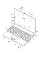
図1および図2は、電子機器としてのポータブルコンピュータ1を開示している。ポータブルコンピュータ1は、本体ユニット2と表示ユニット3とを備えている。本体ユニット2は、偏平な箱状の第1の筐体4を有している。第1の筐体4は、例えばマグネシウム合金のような金属材料で作られており、底壁4a、上壁4b、左右の側壁4c、前壁4dおよび後壁4eを備えている。 1 and 2 disclose a
第1の筐体4は、ベース5とトップカバー6とで構成されている。ベース5は、底壁4a、側壁4c、前壁4dおよび後壁4eを有している。トップカバー6は、上壁4bを有し、ベース5の上端開口を閉塞している。 The
第1の筐体4の側壁4cと後壁4eとで規定される角部に凹部7a,7bが形成されている。凹部7a,7bは第1の筐体4の後端に位置するとともに、第1の筐体4の幅方向に互いに離れている。
第1の筐体4は、キーボード取り付け部8とバッテリ収容部9とを備えている。キーボード取り付け部8は、上壁4bの上面に開口する矩形状の凹所であり、キーボード10を支持している。バッテリ収容部9は、キーボード10の背後に位置している。バッテリ収容部9は、第1の筐体4の底壁4a、上壁4bおよび後壁4eに連続して開口する凹所であり、バッテリパック11を取り外し可能に支持している。 The
表示ユニット3は、第2の筐体13と液晶表示装置14とを備えている。第2の筐体13は、第1の筐体4と略同じ大きさの偏平な箱状であり、その一端に一対の脚部15a,15bを有している。脚部15a,15bは、第2の筐体13の幅方向に互いに離れているとともに、第1の筐体4の凹部7a,7bに入り込んでいる。 The
第2の筐体13は、液晶表示装置14を支持するLCDカバー16と、このLCDカバー16に被せられたLCDマスク17とを備えている。液晶表示装置14は、画像を表示するスクリーン14aを有している。スクリーン14aは、LCDマスク17に形成した開口部18を通じて第2の筐体13の外方に露出している。 The
図2に示すように、第1の筐体4のベース5は、一対のヒンジ支持部20a,20bを有している。一方のヒンジ支持部20aは、左側の凹部7aとバッテリ収容部9の左端部との間に位置している。他方のヒンジ支持部20bは、右側の凹部7bとバッテリ収容部9の右端部との間に位置している。これらヒンジ支持部20a,20bは、金属製の第1および第2のヒンジ装置21,22を介して表示ユニット3を回動可能に支持している。 As shown in FIG. 2, the
表示ユニット3は、閉じ位置と開き位置との間で回動可能となっている。閉じ位置では、表示ユニット3は本体ユニット2の上に横たわり、キーボード10を上方から覆い隠すようになっている。開き位置では、表示ユニット3は本体ユニット2の後端部から起立しており、これによりキーボード10およびスクリーン14aが露出するようになっている。 The
第1のヒンジ装置21は、ベース5の一方のヒンジ支持部20aと第2の筐体13の左側の脚部15aとの間に跨っている。第2のヒンジ装置22は、ベース5の他方のヒンジ支持部20bと第2の筐体13の右側の脚部15bとの間に跨っている。 The
第1および第2のヒンジ装置21,22は、互いに共通の構成を有するとともに、第1および第2の筐体4,13に対する固定の仕方も同様となっている。 The first and
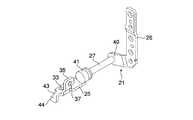
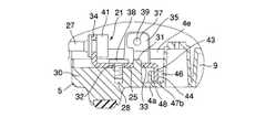
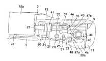
図3および図4に示すように、第1および第2のヒンジ装置21,22は、夫々第1のブラケット25、第2のブラケット26およびヒンジ軸27を有している。第1のブラケット25は、ベース5のヒンジ支持部20a,20bに位置している。図5および図9に示すように、ヒンジ支持部20a,20bは、夫々ねじ孔28を有するボス部29、支持壁30および位置決めピン31を有している。ボス部29、支持壁30および位置決めピン30は、ベース5の底壁4aから上向きに突出するとともに、ベース5の幅方向に沿って一列に並んでいる。ボス部29の上端および支持壁30の上端は、同一面上に位置している。位置決めピン31の上端は、ボス部29や支持壁30の上端よりも上方に突出している。 As shown in FIGS. 3 and 4, the first and
第1のブラケット25は、ボス部29および支持壁30の上端に重なり合う大きさの板状をなしている。第1のブラケット25は、ねじ孔28に合致する挿通孔32と、位置決めピン31が嵌まり込む係合部としての係合孔33を有している。 The
さらに、第1のブラケット25は、軸受部34と固定片35とを有している。軸受部34は、第1のブラケット25の一端から上向きに直角に折り曲げられており、上記ベース5の内側で凹部7a,7bと向かい合うようになっている。固定片35は、ベース5の後壁4eと向かい合うように、第1のブラケット25の他端から上向きに折り曲げられている。この固定片35の上端部には、後壁4eに開けた挿通孔36に連なるねじ孔37が形成されている。 Further, the
図6ないし図8に示すように、上記第1および第2のヒンジ装置21,22の第1のブラケット25は、夫々二本のねじ38,39を介してベース5のヒンジ支持部20a,20bに固定されている。一方のねじ38は、ベース5の上方から挿通孔32を通じてボス部29のねじ孔28にねじ込まれている。他方のねじ39は、ベース5の後方から挿通孔36を通じてねじ孔37にねじ込まれている。このため、第1のブラケット25は、ベース5の底壁4aおよび後壁4eの双方に支持されている。 As shown in FIGS. 6 to 8, the
図5に一方を代表して示すように、第2のブラケット26は、LCDカバー16の側壁16aの内面に図示しないねじを介して固定されている。第2のブラケット26は、一端に軸受部40を有している。軸受部40は、第2の筐体13の脚部15bの内側に位置している。 As representatively shown in FIG. 5, the
ヒンジ軸27は、第1のブラケット25の軸受部34と第2のブラケット26の軸受部40との間に跨っており、ポータブルコンピュータ1の幅方向に沿って水平に配置されている。ヒンジ軸27の一端は、第2のブラケット26の軸受部40に固定されている。ヒンジ軸27の他端は、第1のブラケット25の軸受部34に軸回り方向に回動可能に連結されており、この連結部分にヒンジ軸27の自由な回動を制限するブレーキ機構41が組み込まれている。したがって、第1のブラケット25と第2のブラケット26は、ヒンジ軸27の軸回り方向に相対的に回動可能となっている。 The
ところで、ポータブルコンピュータ1を組み立てる段階において、第1および第2のヒンジ装置21,22は、LCDカバー16に組み付けられており、第1および第2のヒンジ装置21,22と表示ユニット3とが一つのアッセンブリとしてユニット化されている。このことから、図2に示すように、第1および第2のヒンジ装置21,22のヒンジ軸27は、脚部15a,15bから第2の筐体13の外方に突出しており、第1のブラケット25が脚部15a,15bの間に位置している。 Incidentally, at the stage of assembling the
第1および第2のヒンジ装置21,22の第1のブラケット25は、表示ユニット3を伴った状態でベース5のヒンジ支持部20a,20bに組み込まれるようになっている。具体的には、第1のブラケット25は、表示ユニット3を起立させた姿勢でベース5のヒンジ支持部20a,20bに導かれ、ねじ38,39を介してヒンジ支持部20a,20bに固定される。 The
この際、第1のブラケット25は、軸受部34とは反対側の他端に係止部43を備えている。係止部43は、第1のブラケット25の他端から下向きに直角に折り曲げられており、その下端に爪部44を有している。爪部44は、係止部43よりもベース5の奥行き方向に沿う寸法が大きく形成されている。 At this time, the
ベース5のヒンジ支持部20a,20bは、第1のブラケット25の他端に対応する位置に保持部46を備えている。保持部46は、一対の壁部47a,47bを有している。壁部47a,47bは、ベース5の底壁4aから上向きに突出するとともに、ベース5の奥行き方向に互いに向かい合っている。言い換えると、壁部47a,47bは、ヒンジ軸27の軸線に対し直交する方向に沿って並んでいる。 The
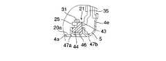
第1のブラケット25をボス部29および支持壁30の上端に重ね合わせた状態では、第1のブラケット25の他端に位置する爪部44が壁部47a,47bの間に介在されるようになっている。このため、壁部47a,47bは、ベース5の前側および後側から爪部44を挟み込んでおり、このことにより、第1のブラケット25がベース5の奥行き方向(前後方向)への移動を規制された状態でヒンジ支持部20a,20bに保持されるようになっている。 In a state where the
さらに、壁部47a,47bは、連結壁部48を介して互いに連結されている。連結壁部48は、ベース5の底壁4aから上向きに突出しており、壁部47a,47bの一端の間に跨っている。この連結壁部48の存在により、壁部47a,47bの強度が充分に確保されている。 Further, the
このような構成のポータブルコンピュータ1において、本体ユニット2に表示ユニット3を連結する手順について説明する。 A procedure for connecting the
図2に示すように、先ず最初に第1および第2のヒンジ装置21,22の第1のブラケット25に対し表示ユニット3を起立させた姿勢に保つ。この状態で第1のブラケット25をベース5の後端部のヒンジ支持部20a,20bに導く。 As shown in FIG. 2, first, the
この時、図11および図12に示すように、ベース5の底壁4aから突出する位置決めピン31を第1のブラケット25の係合孔33に挿入するとともに、底壁4aから突出する壁部47a,47bの間に第1のブラケット25の爪部44を嵌め込む。 At this time, as shown in FIGS. 11 and 12, the
位置決めピン31が係合孔33に挿入することにより、第1のブラケット25とボス部29との位置決めがなされる。このため、ヒンジ軸27の軸方向および第1の筐体4の奥行き方向への第1のブラケット25の移動が規制され、第1のブラケット25の挿通孔32がボス部29のねじ孔28と合致する。 When the
さらに、図10ないし図12に示すように、第1のブラケット25の爪部44が壁部47a,47bに引っ掛かり、これら壁部47a,47bによって第1の筐体4の前側および後側から挟み込まれる。これにより、第1のブラケット25がヒンジ支持部20a,20bに保持され、ベース5の前方又は後方への表示ユニット3の倒れ込みが阻止される。 Further, as shown in FIGS. 10 to 12, the
したがって、第1および第2のヒンジ装置21,22の第1のブラケット25は、表示ユニット3を起立させたままの姿勢でベース5のヒンジ支持部20a,20bに仮止めされる。 Accordingly, the
次に、ねじ38,39を挿通孔32,36からねじ孔28,37にねじ込む。このねじ込みにより、第1および第2のヒンジ装置21,22の第1のブラケット25がベース5のヒンジ支持部20a,20bに固定され、本体ユニット2と表示ユニット3の連結が完了する。 Next, the
このような本発明の実施の形態によると、第1の筐体4のヒンジ支持部20a,20bに、夫々第1および第2のヒンジ装置21,22の第1のブラケット25を挟み込んで保持する壁部47a,47bを設けている。 According to such an embodiment of the present invention, the
このため、第1および第2のヒンジ装置21,22の第1のブラケット25をねじ38,39でヒンジ支持部20a,20bに固定するまでの期間中、表示ユニット3が本体ユニット2の前方又は後方に倒れることがないように、第1のブラケット25をヒンジ支持部20a,20bに仮止めすることができる。 Therefore, during the period until the
したがって、第1のブラケット25をねじ38,39を用いてヒンジ支持部20a,20bに固定する際に、表示ユニット3を手で支える必要はなく、ポータブルコンピュータ1の組み立て作業を容易に行うことができる。 Therefore, when the
さらに、上記構成によると、第1のブラケット25が固定されるベース5は、合成樹脂よりも剛性が高い金属製であるから、表示ユニット3を回動させた時に第1のブラケット25から加わる力に対して充分に対抗できる。このため、ベース5と第1のブラケット25との連結部分を小型・軽量化することができ、第1のブラケット25のコンパクト化に貢献するといった利点がある。 Further, according to the above configuration, the
なお、上記実施の形態においては、ベースの底壁から起立する壁部の間に第1のブラケットの係止部を差し込むようにしたが、本発明はこれに制約されるものではない。例えばベースの底壁に互いに向かい合う支持面を有する凹部を形成し、この凹部の支持面の間に第1のブラケットの係止部を差し込むようにしてもよい。 In the above embodiment, the locking portion of the first bracket is inserted between the wall portions standing from the bottom wall of the base, but the present invention is not limited to this. For example, a recess having support surfaces facing each other may be formed on the bottom wall of the base, and the locking portion of the first bracket may be inserted between the support surfaces of the recess.
さらに、本発明に係る電子機器は、ポータブルコンピュータに限らず、例えば開閉可能な液晶モニターを有するDVDプレーヤであっても同様に実施可能である。 Furthermore, the electronic apparatus according to the present invention is not limited to a portable computer, and can be implemented in the same manner even for a DVD player having a liquid crystal monitor that can be opened and closed.
4…第1の筐体、13…第2の筐体、21,22…ヒンジ装置(第1のヒンジ装置、第2のヒンジ装置)、25…第1のブラケット、26…第2のブラケット、27…ヒンジ軸、43…係止部、46…保持部。 DESCRIPTION OF
Claims (11)
Translated fromJapanese上記第1の筐体とは別の第2の筐体と、
上記第1の筐体と上記第2の筐体とを回動可能に連結するヒンジ装置と、を具備し、
上記ヒンジ装置は、上記第1の筐体に固定される第1のブラケットと、上記第2の筐体に固定される第2のブラケットと、上記第1のブラケットと上記第2のブラケットとを相対的に回動可能に連結するヒンジ軸とを含み、
上記第1の筐体は、上記第1のブラケットに対応する位置に保持部を有し、この保持部は、上記第1のブラケットを挟み込むことにより上記第2の筐体を伴う上記ヒンジ装置を上記第1の筐体に保持することを特徴とする電子機器。A first housing;
A second housing different from the first housing;
A hinge device that rotatably connects the first housing and the second housing;
The hinge device includes a first bracket fixed to the first housing, a second bracket fixed to the second housing, the first bracket, and the second bracket. A hinge shaft that is relatively pivotally connected,
The first housing has a holding portion at a position corresponding to the first bracket, and the holding portion sandwiches the first bracket so that the hinge device with the second housing is attached. An electronic device, wherein the electronic device is held in the first housing.
上記第1の筐体とは別の第2の筐体と、
上記第1の筐体と上記第2の筐体との間を回動可能に連結するヒンジ装置と、を具備し、
上記ヒンジ装置は、上記第1の筐体に固定される第1のブラケットと、上記第2の筐体に固定される第2のブラケットと、上記第1のブラケットと上記第2のブラケットとを相対的に回動可能に連結するとともに、上記第1および第2の筐体の幅方向に延びるヒンジ軸とを含み、
上記第1の筐体は、上記第1のブラケットに対応する位置に保持部を有するとともに、上記第1のブラケットは、上記保持部に嵌合する係止部を有し、これら保持部と係止部との嵌合により、上記第2の筐体を伴う上記ヒンジ装置が上記ヒンジ軸と交差する方向への移動を規制された状態で上記第1の筐体に保持されることを特徴とする電子機器。A first housing;
A second housing different from the first housing;
A hinge device that pivotably connects between the first housing and the second housing;
The hinge device includes a first bracket fixed to the first housing, a second bracket fixed to the second housing, the first bracket, and the second bracket. A hinge shaft that is coupled to be relatively rotatable and extends in the width direction of the first and second housings,
The first casing has a holding portion at a position corresponding to the first bracket, and the first bracket has a locking portion that fits into the holding portion. The hinge device with the second housing is held by the first housing in a state in which movement in the direction intersecting the hinge axis is restricted by fitting with a stop portion. Electronic equipment.
第2の筐体に固定される第2のブラケットと、
上記第1のブラケットと上記第2のブラケットの間に跨るヒンジ軸とを備え、上記ヒンジ軸を支点に上記第1の筐体と上記第2の筐体とを相対的に回動可能に連結するヒンジ装置であって、
上記第1のブラケットは、上記第1の筐体に引っ掛かることで上記ヒンジ軸、上記第2のブラケットおよび上記第2の筐体を含む一つのユニットを上記第1の筐体に保持する係止部を有することを特徴とするヒンジ装置。A first bracket fixed to the first housing;
A second bracket fixed to the second housing;
A hinge shaft straddling between the first bracket and the second bracket is provided, and the first housing and the second housing are connected to each other so as to be relatively rotatable with the hinge shaft as a fulcrum. A hinge device for
The first bracket is hooked to the first casing, thereby holding the unit including the hinge shaft, the second bracket, and the second casing on the first casing. The hinge apparatus characterized by having a part.
Priority Applications (3)
| Application Number | Priority Date | Filing Date | Title |
|---|---|---|---|
| JP2003400892AJP2005165478A (en) | 2003-11-28 | 2003-11-28 | Electronic device and hinge device used in the electronic device |
| US10/994,528US20050115025A1 (en) | 2003-11-28 | 2004-11-23 | Electronic apparatus having a rotatable display unit and hinge device used for the same |
| CN200410097304.0ACN1621999A (en) | 2003-11-28 | 2004-11-26 | Electronic apparatus having a rotatable display unit and hinge device used for the same |
Applications Claiming Priority (1)
| Application Number | Priority Date | Filing Date | Title |
|---|---|---|---|
| JP2003400892AJP2005165478A (en) | 2003-11-28 | 2003-11-28 | Electronic device and hinge device used in the electronic device |
Publications (1)
| Publication Number | Publication Date |
|---|---|
| JP2005165478Atrue JP2005165478A (en) | 2005-06-23 |
Family
ID=34616682
Family Applications (1)
| Application Number | Title | Priority Date | Filing Date |
|---|---|---|---|
| JP2003400892APendingJP2005165478A (en) | 2003-11-28 | 2003-11-28 | Electronic device and hinge device used in the electronic device |
Country Status (3)
| Country | Link |
|---|---|
| US (1) | US20050115025A1 (en) |
| JP (1) | JP2005165478A (en) |
| CN (1) | CN1621999A (en) |
Cited By (7)
| Publication number | Priority date | Publication date | Assignee | Title |
|---|---|---|---|---|
| JP2008298279A (en)* | 2007-06-04 | 2008-12-11 | Toshiba Corp | Electronic device and hinge device used in the electronic device |
| JP2010009387A (en)* | 2008-06-27 | 2010-01-14 | Fujitsu Ltd | Assembly and electronic apparatus |
| JP2011134281A (en)* | 2009-12-25 | 2011-07-07 | Toshiba Corp | Electronic apparatus |
| JP2011134188A (en)* | 2009-12-25 | 2011-07-07 | Toshiba Corp | Electronic apparatus |
| US8225338B2 (en) | 2010-04-09 | 2012-07-17 | Funai Electric Co., Ltd. | Electronic apparatus |
| JP2012137884A (en)* | 2010-12-24 | 2012-07-19 | Toshiba Corp | Electronic device |
| JP2014029171A (en)* | 2012-07-31 | 2014-02-13 | Fujitsu Ltd | Hinge device, and electronic apparatus using the same |
Families Citing this family (9)
| Publication number | Priority date | Publication date | Assignee | Title |
|---|---|---|---|---|
| JP4192175B2 (en)* | 2005-12-27 | 2008-12-03 | 株式会社東芝 | Electronics |
| JP4405532B2 (en)* | 2007-07-04 | 2010-01-27 | シャープ株式会社 | Foldable mobile phone |
| JP5070003B2 (en)* | 2007-10-30 | 2012-11-07 | ニスカ株式会社 | Image reading apparatus and image forming system |
| CN103369877A (en)* | 2012-03-29 | 2013-10-23 | 鸿富锦精密工业(深圳)有限公司 | Electronic device and rotating shaft structure locking method thereof |
| US9015903B2 (en)* | 2013-09-20 | 2015-04-28 | Hewlett-Packard Development Company, L.P. | Pin connector |
| CN104806858A (en)* | 2014-01-24 | 2015-07-29 | 华硕电脑股份有限公司 | Limiting structure and electronic device with limiting structure |
| CN107435681B (en)* | 2016-05-27 | 2020-08-18 | 神讯电脑(昆山)有限公司 | Pivot device and electronic device with same |
| US9976326B2 (en)* | 2016-06-24 | 2018-05-22 | Getac Technology Corporation | Hinge device and electronic device having the same |
| US11301003B2 (en)* | 2019-09-24 | 2022-04-12 | Getac Technology Corporation | Eletronic device with anti-shock function |
Family Cites Families (12)
| Publication number | Priority date | Publication date | Assignee | Title |
|---|---|---|---|---|
| JP3382073B2 (en)* | 1995-09-19 | 2003-03-04 | 株式会社東芝 | Portable electronic devices |
| DE69832752T2 (en)* | 1997-05-06 | 2006-09-07 | Samsung Electronics Co., Ltd., Suwon | Swivel device and portable computer with swivel device |
| US6584646B2 (en)* | 2000-02-29 | 2003-07-01 | Katoh Electrical Machinery Co., Ltd. | Tilt hinge for office automation equipment |
| US20040049886A1 (en)* | 2002-09-17 | 2004-03-18 | Shin Zu Shing Co., Ltd. | Elastic hinge for a notebook computer |
| KR20040061122A (en)* | 2002-12-30 | 2004-07-07 | 삼성전자주식회사 | Hinge apparatus and Electric-Electronic apparatus with the Hinge |
| US6804859B2 (en)* | 2003-01-10 | 2004-10-19 | Shin Zu Shing Co., Ltd. | Securing device for a laptop computer hinge to avoid damping of a screen when the screen is away from mainframe of the laptop computer |
| JP2004234194A (en)* | 2003-01-29 | 2004-08-19 | Toshiba Corp | Electronics |
| US6779234B1 (en)* | 2003-04-14 | 2004-08-24 | Shin Zu Shing Co., Ltd. | Elastic hinge for a notebook computer |
| TW572346U (en)* | 2003-04-23 | 2004-01-11 | Hon Hai Prec Ind Co Ltd | Power control structure for an LCD |
| KR100542354B1 (en)* | 2003-10-13 | 2006-01-10 | 삼성전자주식회사 | Electronic device with improved hinge |
| US7124473B2 (en)* | 2004-12-07 | 2006-10-24 | Shin Zu Shing Co., Ltd. | Hinge for a notebook computer |
| JP4537843B2 (en)* | 2004-12-22 | 2010-09-08 | 株式会社東芝 | Electronics |
- 2003
- 2003-11-28JPJP2003400892Apatent/JP2005165478A/enactivePending
- 2004
- 2004-11-23USUS10/994,528patent/US20050115025A1/ennot_activeAbandoned
- 2004-11-26CNCN200410097304.0Apatent/CN1621999A/enactivePending
Cited By (10)
| Publication number | Priority date | Publication date | Assignee | Title |
|---|---|---|---|---|
| JP2008298279A (en)* | 2007-06-04 | 2008-12-11 | Toshiba Corp | Electronic device and hinge device used in the electronic device |
| JP2010009387A (en)* | 2008-06-27 | 2010-01-14 | Fujitsu Ltd | Assembly and electronic apparatus |
| JP2011134281A (en)* | 2009-12-25 | 2011-07-07 | Toshiba Corp | Electronic apparatus |
| JP2011134188A (en)* | 2009-12-25 | 2011-07-07 | Toshiba Corp | Electronic apparatus |
| US8144477B2 (en) | 2009-12-25 | 2012-03-27 | Kabushiki Kaisha Toshiba | Electronic device having a hinge |
| US8506024B2 (en) | 2009-12-25 | 2013-08-13 | Kabushiki Kaisha Toshiba | Electronic apparatus |
| US8225338B2 (en) | 2010-04-09 | 2012-07-17 | Funai Electric Co., Ltd. | Electronic apparatus |
| JP2012137884A (en)* | 2010-12-24 | 2012-07-19 | Toshiba Corp | Electronic device |
| US8520379B2 (en) | 2010-12-24 | 2013-08-27 | Kabushiki Kaisha Toshiba | Electronic apparatus |
| JP2014029171A (en)* | 2012-07-31 | 2014-02-13 | Fujitsu Ltd | Hinge device, and electronic apparatus using the same |
Also Published As
| Publication number | Publication date |
|---|---|
| CN1621999A (en) | 2005-06-01 |
| US20050115025A1 (en) | 2005-06-02 |
Similar Documents
| Publication | Publication Date | Title |
|---|---|---|
| JP2005165478A (en) | Electronic device and hinge device used in the electronic device | |
| JP2986180B2 (en) | Portable equipment | |
| JP2005157789A (en) | Electronics | |
| KR930008256B1 (en) | Portable computer w/pdp | |
| JP2007328613A (en) | Electronics | |
| JP4444356B1 (en) | Electronics | |
| JP2008141139A (en) | Electronic device, flexible substrate and substrate fixing member | |
| US7164577B2 (en) | Electronic apparatus having storage device | |
| JP5524712B2 (en) | Electronic device storage box | |
| JP2011134188A (en) | Electronic apparatus | |
| CN101377695A (en) | Electronic device | |
| JP4724245B2 (en) | Electronics | |
| JP2006091713A (en) | Display device | |
| JP5467450B2 (en) | Sealing structure of control board | |
| JP2011249474A (en) | Electronic device housing | |
| JP2005221823A (en) | Display device | |
| JP4643746B2 (en) | Electronics | |
| JPH0726745Y2 (en) | Computer device with display | |
| JP6412772B2 (en) | Enclosure | |
| JP2006202817A (en) | Electronic apparatus having connector terminal | |
| JP6631083B2 (en) | Information processing equipment | |
| JP2001318735A (en) | Notebook type information processor | |
| JP2011082183A (en) | Electronic apparatus | |
| JP4052161B2 (en) | Opening and closing structure of the housing | |
| JP5666006B2 (en) | Electronic equipment housing |