JP2005160107A - Resolution adaptive image filtering system and method - Google Patents
Resolution adaptive image filtering system and methodDownload PDFInfo
- Publication number
- JP2005160107A JP2005160107AJP2004342631AJP2004342631AJP2005160107AJP 2005160107 AJP2005160107 AJP 2005160107AJP 2004342631 AJP2004342631 AJP 2004342631AJP 2004342631 AJP2004342631 AJP 2004342631AJP 2005160107 AJP2005160107 AJP 2005160107A
- Authority
- JP
- Japan
- Prior art keywords
- image
- sampling rate
- image data
- pixel
- point spread
- Prior art date
- Legal status (The legal status is an assumption and is not a legal conclusion. Google has not performed a legal analysis and makes no representation as to the accuracy of the status listed.)
- Granted
Links
Images


Classifications
- G—PHYSICS
- G06—COMPUTING OR CALCULATING; COUNTING
- G06T—IMAGE DATA PROCESSING OR GENERATION, IN GENERAL
- G06T3/00—Geometric image transformations in the plane of the image
- G06T3/40—Scaling of whole images or parts thereof, e.g. expanding or contracting
- G06T3/4084—Scaling of whole images or parts thereof, e.g. expanding or contracting in the transform domain, e.g. fast Fourier transform [FFT] domain scaling
- G—PHYSICS
- G06—COMPUTING OR CALCULATING; COUNTING
- G06T—IMAGE DATA PROCESSING OR GENERATION, IN GENERAL
- G06T5/00—Image enhancement or restoration
- G06T5/20—Image enhancement or restoration using local operators
- G—PHYSICS
- G06—COMPUTING OR CALCULATING; COUNTING
- G06T—IMAGE DATA PROCESSING OR GENERATION, IN GENERAL
- G06T5/00—Image enhancement or restoration
- G06T5/70—Denoising; Smoothing
- G—PHYSICS
- G06—COMPUTING OR CALCULATING; COUNTING
- G06T—IMAGE DATA PROCESSING OR GENERATION, IN GENERAL
- G06T5/00—Image enhancement or restoration
- G06T5/73—Deblurring; Sharpening
- G—PHYSICS
- G06—COMPUTING OR CALCULATING; COUNTING
- G06T—IMAGE DATA PROCESSING OR GENERATION, IN GENERAL
- G06T2207/00—Indexing scheme for image analysis or image enhancement
- G06T2207/20—Special algorithmic details
- G06T2207/20004—Adaptive image processing
- G06T2207/20012—Locally adaptive
- G—PHYSICS
- G06—COMPUTING OR CALCULATING; COUNTING
- G06T—IMAGE DATA PROCESSING OR GENERATION, IN GENERAL
- G06T2207/00—Indexing scheme for image analysis or image enhancement
- G06T2207/20—Special algorithmic details
- G06T2207/20172—Image enhancement details
- G06T2207/20192—Edge enhancement; Edge preservation
- G—PHYSICS
- G06—COMPUTING OR CALCULATING; COUNTING
- G06T—IMAGE DATA PROCESSING OR GENERATION, IN GENERAL
- G06T2207/00—Indexing scheme for image analysis or image enhancement
- G06T2207/30—Subject of image; Context of image processing
- G06T2207/30004—Biomedical image processing
Landscapes
- Physics & Mathematics (AREA)
- General Physics & Mathematics (AREA)
- Engineering & Computer Science (AREA)
- Theoretical Computer Science (AREA)
- Image Processing (AREA)
- Apparatus For Radiation Diagnosis (AREA)
- Magnetic Resonance Imaging Apparatus (AREA)
- Studio Circuits (AREA)
Abstract
Translated fromJapaneseDescription
Translated fromJapanese本発明は、デジタルイメージング及び画像強調の分野に関する。より詳細には、本発明は、データに対する最適サンプリングレートに基づいて入力画像データを適切にフィルタ処理することによって、画像強調を改善する技法に関する。 The present invention relates to the field of digital imaging and image enhancement. More particularly, the present invention relates to techniques for improving image enhancement by appropriately filtering input image data based on an optimal sampling rate for the data.
デジタル画像を生成するための多くの技法が現在利用可能であり、使用されている。これらの技法は、複雑性において、簡単な写真技法から医療用イメージング、部品検査、小荷物及び手荷物検査等に用いられるようなはるかに複雑なイメージング診断装置にまで多岐にわたっている。更に複雑なイメージング診断装置には、コンピュータ断層撮影(CT)イメージングシステム、磁気共鳴イメージング(MRI)システム、デジタルX線イメージングシステム等が含まれる。これらの用途の全てにおいて、生成される画像の分解能及び明瞭度の改善に対する継続的な必要性がある。一般に、これらの改善は後処理段階で施され、該段階では、画像データが種々の計算に操作されて最終再構成画像の明瞭度及び全体的有用性が高められる。 Many techniques for generating digital images are currently available and in use. These techniques range in complexity from simple photographic techniques to much more complex imaging diagnostic devices such as those used for medical imaging, parts inspection, parcel and baggage inspection, and the like. More complex imaging diagnostic devices include computed tomography (CT) imaging systems, magnetic resonance imaging (MRI) systems, digital X-ray imaging systems, and the like. In all of these applications, there is a continuing need for improved resolution and clarity of the generated image. In general, these improvements are made in a post-processing stage, where the image data is manipulated into various calculations to increase the clarity and overall usefulness of the final reconstructed image.
現在のイメージングシステムは、異なる空間分解能の画像を生成する。システムの点像分布関数として知られるパラメータは、イメージングパラメータに大きく依存しており、その結果このような異なる空間分解能が得られる。例えば、CT画像では、収集したデータを画像データに変換するために用いられる特定の再構成アルゴリズムが、点像分布関数の範囲を主として決定する。同様に、MRIシステムでは、k−空間データ(イメージングシーケンス中に収集されたデータ)におけるゼロ充填補間の量が、点像分布関数の空間範囲に影響を及ぼす。X線システムでは、線源−検出器間距離が、システムの点像分布関数を決定する。 Current imaging systems produce images with different spatial resolutions. The parameter known as the point spread function of the system is highly dependent on the imaging parameters, resulting in such different spatial resolutions. For example, in a CT image, the specific reconstruction algorithm used to convert the collected data into image data mainly determines the range of the point spread function. Similarly, in an MRI system, the amount of zero-fill interpolation in k-space data (data collected during the imaging sequence) affects the spatial extent of the point spread function. In an X-ray system, the source-detector distance determines the system's point spread function.
画像から不規則ノイズを除去することを意図した画像フィルタ処理アルゴリズムは、現在、固有空間分解能のこのばらつきに対応していない。従って、このようなアルゴリズムは、画質の観点からは最適とは言えない状態で機能する。こうした枠組みにおいて、これらが不規則ノイズのレベルを首尾よく低下させることができたとしても、フィルタ処理画像の空間分解能に損失を生じさせる場合が多い。 Image filtering algorithms intended to remove random noise from images do not currently address this variation in eigenspace resolution. Therefore, such an algorithm functions in a state that is not optimal from the viewpoint of image quality. In such a framework, even if they can successfully reduce the level of random noise, they often cause a loss in the spatial resolution of the filtered image.
従って、デジタル画像をフィルタ処理するための改良された技法が必要とされている。現在、様々な状況において用いることができ、異なる点像分布関数ベースに対応する技法が特に必要とされている。 Therefore, there is a need for improved techniques for filtering digital images. Currently, there is a particular need for techniques that can be used in a variety of situations and that accommodate different point spread function bases.
本発明は、このような必要性に応えるように設計される画像強調法に対する新規の技法を提供する。本技法は、フィルタ処理画像の空間分解能を犠牲にすることなく画像のノイズレベルを低減する画像フィルタ処理アルゴリズムに基づいている。本技法は、フィルタ処理中の画像の固有空間分解能のばらつきに自動的に適応する。詳細には、本技法は、画像の点像分布関数などから最適サンプリングレートを決定する。また、画像の帯域幅特性を調べることによって点像分布関数を推定することも可能である。この最適サンプリングレートは、実際の画素サンプリングレートと比較される。フィルタ処理中、この比較に基づいて、最適サンプリングレートに対応してこれに適合するよう画像を縮小することができる。或いは、特定の状況においては、データの再サンプリングを行うこともできる。 The present invention provides a novel technique for image enhancement methods designed to meet these needs. The technique is based on an image filtering algorithm that reduces the noise level of the image without sacrificing the spatial resolution of the filtered image. The technique automatically adapts to variations in the intrinsic spatial resolution of the image being filtered. Specifically, the present technique determines an optimal sampling rate, such as from a point spread function of the image. It is also possible to estimate the point spread function by examining the bandwidth characteristics of the image. This optimal sampling rate is compared with the actual pixel sampling rate. During filtering, based on this comparison, the image can be scaled down to accommodate and match the optimal sampling rate. Alternatively, in certain circumstances, data can be resampled.
本発明は、このような技法を実施するように設計された方法、システム及びコンピュータプログラムを企図している。 The present invention contemplates methods, systems, and computer programs designed to implement such techniques.
本発明の前述及び他の利点並びに特徴は、以下の詳細な説明を読み且つ図面を参照すれば明らかになるであろう。 The foregoing and other advantages and features of the invention will become apparent upon reading the following detailed description and upon reference to the drawings in which:
図1を参照すると、個別の画像データを収集し処理する回路に接続されたスキャナ又はデータ収集システム12を含むイメージングシステム10が示されている。システム12によって感知された信号は、被検体上又は被検体内の特定の位置に関連する信号を表すデジタル値を与えるよう符号化されて、画像収集回路22に伝送される。画像収集回路22はまた、画像収集中のシステム動作の構成及び調整用の制御信号を供給する。画像収集回路22は、符号化された画像信号を画像処理回路24に伝送する。画像処理回路24は、記憶回路26内に格納された事前確定された制御論理ルーチンを実行し、画像収集回路22から受信した信号をフィルタ処理して調整し、該収集された画像内の各画素を表すデジタル値を形成する。その後、これらの値は、後続の処理及び表示のために記憶回路26内に格納される。或いは、画像収集回路22は、符号化された画像信号を記憶回路26に伝送してもよい。画像処理回路24は、以下に説明するフィルタ処理段階及び調整段階のために引き続き記憶回路26から信号を収集することができる。 Referring to FIG. 1, an
画像処理回路24は、入力インターフェース回路30を介して、入力装置28から構成指令及び制御指令を受け取る。入力装置28は、通常、構成パラメータを選択的に入力し且つ特定の画像収集シーケンスを指令するためのオペレータステーション、キーボード及び他の入力装置を含むことになる。画像処理回路24もまた、出力インターフェース回路34を介して出力装置32に接続される。出力装置32は、通常、処理回路24によって実行される画像強調処理に基づいた再構成画像を閲覧及び生成するためのモニタ又はプリンタを含むことになる。 The
説明される実施形態において、画像処理回路24、記憶回路26、並びに入力及び出力インターフェース回路30及び34は、プログラムされたデジタルコンピュータ内に含まれる。しかしながら、本明細書に説明する技法を実行する回路構成は、特定用途向けマイクロプロセッサ、アナログ回路構成、又はデジタル回路構成とアナログ回路構成の組み合わせにおいて適切に符号化されるよう構成することができる。 In the described embodiment,
イメージングシステム12は、任意の好適な形式のイメージングシステム又は診断装置を含むことができる点に留意すべきである。例えば、医学的診断用イメージング関連、工業用関連、小荷物及び手荷物の検査及び出荷関連においては、本システムは、CTイメージングステーションを含むことができる。同様に、本システムは、MRIシステム、X線システム、又は任意の他の好適な診断装置を含むことができる。現在企図されている他の診断装置は、とりわけ、トモシンセシスシステム、陽電子放射断層撮影システム、電子ビームシステム、超音波システムを含むことができる。以下に要約するように、種々のシステムの全てが、本技法によりフィルタ処理及び強調を施すことができるデジタルデータを生成することになる。また、本明細書ではイメージングシステム内における処理に言及しているが、本明細書で説明する技法の多くは、後処理段階に適用可能であり、且つ適用される点に留意すべきである。即ち、本処理は、画像収集と共にリアルタイム又はほぼリアルタイムで実行してもよく、或いは画像データの収集及び格納後に実行してもよい。従って、本明細書に説明する画像のフィルタ処理及び強調技法は、最終再構成画像を改善するために、未処理、又は処理済、若しくは部分的に処理済の画像データにアクセスして本明細書に説明する段階及び機能を実行する完全に別個の独立したワークステーション上のような、イメージングシステムから遠隔の位置で実行することができる。 It should be noted that the
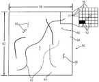
図2は、イメージングシステム10によって生成される例示的な離散的画素画像50を示す。画像50は、一連の横列54及び縦列56内に互いに隣接して配置された離散的画素52のマトリックスから構成されている。これらの画素の横列及び縦列は、事前確定されたマトリックス幅58及びマトリックス高さ60を備える。典型的なマトリックス寸法は、幾つか例を挙げると、256×256画素、512×512画素、1、024×1、024画素を含むことができる。幾つかのシステムにおいては、特定の画像マトリックスサイズは、入力装置28(図1参照)を介して選択することができ、撮像対象、所望の分解能、及びイメージングシステムの物理的形態又は特性などの要因に応じて様々とすることができる。 FIG. 2 illustrates an exemplary
図2に示すように、例示的な画像50は、隣接する画素によって画定される長い連続した線からなるように示された構造領域62を含む。画像50はまた、構造領域62の外側に位置する非構造領域64を含む。画像50はまた、種々の大きさ(即ち、隣接する画素の数)の隔離されたアーチファクト66を含む場合があり、これは構造領域として定義されるか、或いは一般的な公知の技法により構造の定義から除外される場合がある。以下の検討においては例示的な画像50のような画像内の強度値に言及するが、本技法はまた、画像の個々の画素52に対して符号化された他のパラメータの処理にも用いることができる点を留意すべきである。このようなパラメータは、単に強度だけでなく周波数又は色相を含むことがでる。 As shown in FIG. 2, the
本技法によれば、収集又は処理された画像データは、入力画像と呼ぶことができるものを形成する。この入力画像及び本明細書中に言及する他の画像は、実際には本技法によって処理された画像データであることを理解されたい。しかしながら、最終再構成画像は、ユーザが閲覧することができる視覚的表現である。本技法は、イメージングシステムの特定の点像分布関数に対応するための入力画像の操作を可能にする。即ち、本技法は、入力画像を生成したイメージングシステムの特性に空間的に適応する。画像フィルタ処理用の既知のアルゴリズムは、空間領域演算のセットを適用して入力画像のノイズレベルを低減する。幾つかの技法は、サブサンプリングと呼ぶことができる操作において、入力画像を縮小することによりそのような演算を実行する。この縮小操作は、入力分解能を正規化する作用を有しており、入力画像内の冗長性を活用する。しかしながら、前述の技法は、画像サイズに依存して縮小又はサブサンプリングの度合いが決定される。本技法は、より厳密な手法を用いており、入力画像を縮小するために行われるサブサンプリングの量は、画像の固有の空間分解能に依存する。本発明の関連において、固有空間分解能は、画像データを収集しているイメージングシステムの点像分布関数と離散画像を生成するのに用いられるサンプリングレートとに依存することができると考えられる。以下に説明するように、このような情報は、イメージングシステムのナイキストレートとして定義することができる最適サンプリングレートを決定するのに用いられる。この値は、空間領域演算を適用する前に画像上で実行すべきサブサンプリング又は縮小の量を決定するのに用いられる。この手法によって、最適なサンプリング基準がアンダーサンプリングによって侵害されないこと、及び画像情報を損失することなく最大量のサンプリングを達成し正規化された分解能で画像上にフィルタ処理を行い且つ画像データ内の冗長性を活用できることが保証される。 According to this technique, the collected or processed image data forms what can be referred to as an input image. It should be understood that this input image and other images referred to herein are actually image data processed by the technique. However, the final reconstructed image is a visual representation that can be viewed by the user. This technique allows manipulation of the input image to accommodate a particular point spread function of the imaging system. That is, the technique spatially adapts to the characteristics of the imaging system that generated the input image. Known algorithms for image filtering apply a set of spatial domain operations to reduce the noise level of the input image. Some techniques perform such operations by reducing the input image in an operation that can be referred to as sub-sampling. This reduction operation has the effect of normalizing the input resolution and takes advantage of the redundancy in the input image. However, the above technique determines the degree of reduction or sub-sampling depending on the image size. The technique uses a more rigorous approach and the amount of subsampling performed to reduce the input image depends on the inherent spatial resolution of the image. In the context of the present invention, it is believed that the intrinsic spatial resolution can depend on the point spread function of the imaging system collecting the image data and the sampling rate used to generate the discrete image. As described below, such information is used to determine an optimal sampling rate that can be defined as the Nyquist rate of the imaging system. This value is used to determine the amount of subsampling or reduction to be performed on the image before applying the spatial domain operation. This approach ensures that the optimal sampling criteria are not violated by undersampling, and that the maximum amount of sampling is achieved without loss of image information, filtering on the image with normalized resolution, and redundancy in the image data. Guaranteeing the use of sex.
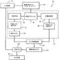
図3は、本技法の機能を実行するシステムの概略図を示す。全体が参照符号68で示される本システムは、ハードウェア、ソフトウェア、ファームウェア、又はこれらの媒体の組み合わせによって実行することができる。本システムは、任意の好適なイメージングシステムによって生成される入力画像70から始まる。入力画像は、通常、デジタル記憶装置上に格納され、画質の向上及び改善のために処理システムによりアクセスされる。本システムは、通常は本システム内に格納された適切なソフトウェアコード内に組み入れられたフィルタ72を含む。本フィルタの幾つかの態様は、以下に更に説明する一般的に知られた技法に従うことができる。本フィルタは、縮小パラメータ決定モジュール74によって決定される縮小レベル又はサブサンプリングレベルを使用する。次いで、このモジュールは、最適サンプリングレート決定モジュール76及び実サンプリングレート決定モジュール78からの入力を受け取る。以下に説明するように、最適サンプリングレート及び実サンプリングレートに基づいて適切な縮小パラメータ又はサブサンプリングレベルが決定され、フィルタ72に供給される。次に、フィルタは、閲覧、格納、伝送、及び後続の処理のために強調画像に再構成することができるデータを含む出力画像80を生成する。 FIG. 3 shows a schematic diagram of a system that performs the functions of the present technique. The system, generally designated by
上述のように、フィルタ72の幾つかの要素は、当該技術分野で一般に良く知られたラインに従うことができる。図4はこれらの既知の要素のうちの幾つかを表しているが、本技法を組み込んだ強化された構成要素を備えている。全体を参照符号82で示す実行システムは、上述のように入力画像70で開始する。段階84で、本システムは、縮小パラメータによって入力画像を縮小するか、又は入力画像をサブサンプリングする。当業者には理解されるように、このような縮小は、各画素での強度を表すデジタル値が読み込まれ、一般に1より大きいある係数Xだけ画像が縮小される、画素平均を含む種々のサブサンプリング技法によって達成することができる。本実施形態では、非重複平均を得るために、2×2又は3×3のボックスカー・フィルタを適用することができる。また、2×3又は3×2フィルタなどの多次元係数を用いることができる。多次元係数は、3×1又は1×3のような次元の少なくとも1つが1より大きくなければならない。非重複平均を得るために、必要に応じて画像の画素を境界においてミラーリングすることができる。 As mentioned above, some elements of the
フィルタ72は、入力画像の構造的特徴及び非構造的特徴又は領域を特定し、処理する役割を果たす。従って、図4のブロック86において、正規化画像内の構造領域88を特定し、このような構造を非構造領域90と区別するルーチンが実行される。次いで、ブロック92に示すように、該構造領域が異方性平滑化によって処理され、その後、ブロックに示すように鮮鋭化によって処理される。他方、非構造領域は、ブロック96に示すように、等方性平滑化によって処理される。その後、処理された構造領域及び非構造領域は、図4に参照符号98で示すようにフィルタ処理画像を形成する。
ブロック100において、ブロック84で画像が縮小又はサブサンプリングされた同じ係数だけ構造データ及び非構造データが拡大される。結果として得られた拡大により、拡大された構造マスク及び拡大画像が生成され、これらの両方ともが入力画像と同一の寸法を有する。次いで、ブロック102において、入力画像内に存在するテクスチャが拡大画像に戻されて混合され、出力画像80が生成される。構造領域と非構造領域の差分的テクスチャ混合を可能にするために、混合処理には、通常、拡大された構造マスクが利用される。 At
図4の例示的な段階及び構成要素が例示にすぎないことに留意すべきであり、当業者であればそのように理解されるであろう。即ち、他の異なる又は付加的モジュール及び段階を組み込むことができる。一例を挙げれば、高周波数が混合画像に差分的に導入されてノイズ混合画像が生成される付加的な混合を行うことができる。これらの技法のうちの幾つかは、更に画質を向上させることができる。本技法は、これらに加えて、以下に説明するように画質を更に向上させることができる。 It should be noted that the exemplary steps and components of FIG. 4 are merely exemplary and will be understood by those skilled in the art. That is, other different or additional modules and steps can be incorporated. As an example, additional mixing can be performed in which a high frequency is differentially introduced into the mixed image to produce a noise mixed image. Some of these techniques can further improve image quality. In addition to these, the present technique can further improve the image quality as described below.
当業者には理解されるように、イメージング診断装置に応じて、点像分布関数は、画像データストリームのヘッダ部分に格納することができる種々のパラメータによって決定することができる。例えば、CT画像においては、主として利用される再構成アルゴリズムが、イメージングシステムの点像分布関数を決定する。CTには有限数の再構成アルゴリズムが用いられるため、各再構成アルゴリズムと関連付けられる点像分布関数を経験的に決定することが可能である。このような関連付けは、参照テーブル内に配置し、本発明の処理枠組み内で用いることができる。MRIシステムに関しては、点像分布関数は、システムによって生成される任意の画像の最高周波数成分を定めるZIPパラメータによって決定される。画像の最高周波数成分が与えられれば、イメージングシステムの点像分布関数を決定するための標準的なフーリエ理論の数多くの方法が存在する。X線システムでは、点像分布関数は、線源−検出器間距離及び線源の大きさから計算することができる。また、この情報は、X線デジタル画像データストリームヘッダにおいても一般に利用可能である。従って、各種のイメージングシステムは一般に、点像分布関数の特定を可能にする利用可能な技法を有する。 As will be appreciated by those skilled in the art, depending on the imaging diagnostic device, the point spread function can be determined by various parameters that can be stored in the header portion of the image data stream. For example, in a CT image, the reconstruction algorithm that is mainly used determines the point spread function of the imaging system. Since a finite number of reconstruction algorithms are used for CT, it is possible to empirically determine the point spread function associated with each reconstruction algorithm. Such associations can be placed in a lookup table and used within the processing framework of the present invention. For MRI systems, the point spread function is determined by ZIP parameters that define the highest frequency component of any image generated by the system. Given the highest frequency component of an image, there are numerous methods of standard Fourier theory for determining the point spread function of an imaging system. In an X-ray system, the point spread function can be calculated from the source-detector distance and the source size. This information is also generally available in the X-ray digital image data stream header. Thus, various imaging systems generally have available techniques that allow the identification of the point spread function.
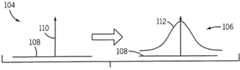
点像分布関数の例示的な図を図5に示す。図5に示すように、理想的な状況104は図示することができるが、実際の実施においては、典型的には点像分布図106が現れる。図5において全体を水平軸108で示す画像画素寸法、及び垂直軸で示す画素強度に関しては、理想的な状況において、図5の参照符号110で示すように、各点は無限に幅が薄い。しかしながら、イメージングシステムの固有の限界に起因してボケが生じ、結果として、図5のトレース112で示すように、画素寸法の広がりが生じる。本技法は、ナイキストレートの約2倍でサンプリングすると情報損失が実質的に回避できることができることを認識している。ナイキストレートは、点像分布関数のフーリエ変換を取ることによって求めることができる。或いは、ナイキストレートは、画像内の最高周波数調波を調べることにより標準的な画像処理技法を用いて計算することができる。しかしながら、この技法は有用ではあるが、システム及び収集パラメータに依存しないことから、画像にノイズの影響を極めて受けやすいことに留意されたい。実際には、点像分布関数の幅が広い場合には、画像が見かけ上非常にぼける可能性があり、上述の処理段階において高度の縮小又はサブサンプリングが必要となる。更に、表示フィールド、即ち再構成画像内の被検体の寸法が全体的に考慮される。以下に説明する表示フィールドに基づいて、冗長性メトリックが求められる。即ち、再構成画像の被検体を表すのに多くの画素が必要とされる場合には、このことは、高度の冗長性を示しており、入力画像はかなりの程度縮小することができる。従って、縮小又はサブサンプリングの度合いも、この冗長性メトリックに依存する。 An exemplary diagram of the point spread function is shown in FIG. As shown in FIG. 5, an
図6には、本技法により適切な縮小又はサブサンプリングのパラメータ及びレベルを決定するための幾つかの論理上の機能的段階を示す。段階114に示すように、このプロセスは、システムの点像分布関数を決定する段階で開始する。上述のように、点像分布関数は、参照テーブルから求めることもでき、或いは計算で求めてもよい。同様に例証として、点像分布関数は、CTイメージングにおける再構成アルゴリズム、MRイメージングにおけるZIPパラメータ、或いはデジタルX線イメージングにおける線源−検出器間距離などの因子に依存することができる。次いで、この点像分布関数から、モジュール76によって最適サンプリングレートが決定される。最適サンプリングレートを決定するために既知の技法が利用可能であり、該技法は、イメージングシステムの点像分布関数に基づいたナイキストレートであると一般に考えられる。このような技法は、点像分布関数の周波数応答の大きさを用いる変調伝達関数の使用を含む。 FIG. 6 illustrates several logical functional steps for determining appropriate reduction or subsampling parameters and levels according to the present technique. As shown in
この処理と並行して、上述の冗長性メトリックを求める。冗長性メトリックは、画素サイズ、即ち、再構成画像内の画素の物理的寸法を求めることによって、図6に示すようにして求められる。当業者には理解されるように、この算出は、表示視野及び画素単位の画像サイズに基づいており、長さの単位(一般的にミリメートル)を有するメトリックが得られる。次いで、モジュール76が、画素サイズから画素サンプリングレートを求める。サンプリングレートは一般に、画素サイズの逆数と考えられ、単位長さ当たりの周期で測定された量が得られる。 In parallel with this processing, the above-described redundancy metric is obtained. The redundancy metric is determined as shown in FIG. 6 by determining the pixel size, ie the physical dimensions of the pixels in the reconstructed image. As will be appreciated by those skilled in the art, this calculation is based on the display field of view and the image size in pixels, resulting in a metric having units of length (typically millimeters). The
次いで、段階118で示すように、Soで示すことができる最適サンプリングレートと、Spで示すことができる画素サンプリングレートとが比較される。一般的に、画素サンプリングレートは最大でも最適サンプリングレートの値であるのが好ましい。このようにして、段階118における比較に基づいて、最適又は望ましい縮小パラメータ或いはサブサンプリングパラメータが求められる。図6に示すように、本発明の実施においては、Soの値が実サンプリングレートSpに等しいか又はそれより大きい場合、縮小パラメータは、1の値に設定される。即ち、画像は最適サンプリングレートよりも低いレートで既にサンプリングされており、従って、どのような付加的な縮小又はサブサンプリングも、アンダーサンプリングをもたらすことになる。これに対して、最適サンプリングレートが画素サンプリングレートよりも低い場合、縮小パラメータ又はサブサンプリングパラメータは、Sp/Soの値に設定される。即ち、画像は、最適レートよりも高いレートでサンプリングされ、画像情報を損失することなく付加的サンプリングを行うことができるようにする。本発明の関連では、Sp/Soの値は、冗長性メトリックとみなすことができる。その後、得られたパラメータは、入力画像の縮小又はサブサンプリングの上述の処理に用いられてフィルタ処理が行われる。Then, as shown at
特定の状況では、未処理データ又は前処理データに基づいて画像データを再サンプリング可能とすることができる点に留意すべきである。この可能性を図6の段階124に示す。例証として、冗長性メトリックが1よりも大きいことが判明した場合には、入力画像に基づいて、例えば周波数領域又は他の領域などにおいて補間を行い得る可能性がある。従って、原画像データを、MRIデータに対しては事例ベースで、或いはCTデータに対してはラドン空間などにおいて再処理を行い、最適サンプリングレートに適合する所望のサンプリングレートを得ることができる。 It should be noted that in certain situations, image data can be resampled based on raw or pre-processed data. This possibility is illustrated in
本発明をフィルタパラメータ調整に対する用途として説明しているが、他の用途もまた可能である。例えば、冗長性メトリックを用いて、最適状態には及ばないデータが収集されているデータ収集システムのオペレータに警報を出すことができる。別の実施例として、冗長性メトリックを用いて、画像データに対して最適表示パラメータを設定することができる。別の実施例では、冗長性メトリックを用いて、画像の計量を導くことができる。更に別の実施例では、冗長性メトリックを用いて、画像解析のパラメータを設定することができる。 Although the present invention has been described as an application to filter parameter adjustment, other applications are also possible. For example, a redundancy metric can be used to alert an operator of a data collection system where data that is less than optimal is being collected. As another example, redundancy metrics can be used to set optimal display parameters for image data. In another embodiment, a redundancy metric can be used to derive a metric for the image. In yet another embodiment, a redundancy metric can be used to set image analysis parameters.
本発明には種々の変更及び代替形態が可能であるが、特定の実施形態を例証として図面に示し、本明細書で詳細に説明してきた。しかしながら、本発明は、開示された特定の形態に限定されることを意図するものではないことを理解すべきである。むしろ、本発明は、添付の特許請求の範囲によって定義される本発明の技術思想及び範囲内に含まれる全ての変更、均等物、及び代替物を包含すべきである。 While the invention is susceptible to various modifications and alternative forms, specific embodiments have been shown by way of example in the drawings and have been described in detail herein. However, it should be understood that the invention is not intended to be limited to the particular forms disclosed. On the contrary, the invention is intended to cover all modifications, equivalents, and alternatives falling within the spirit and scope of the invention as defined by the appended claims.
68 本システム
70 入力画像
72 フィルタ
74 縮小パラメータを決定する
76 最適サンプリングレートを決定する
78 実サンプリングレートを決定する
80 出力画像68
Claims (10)
Translated fromJapanese前記画像データに対する画素サンプリングレート(78)を決定する段階と、
前記画素サンプリングレートを所望のサンプリングレート(76)と比較する段階と、
前記比較に基づいて縮小パラメータ(74)を求める段階と、
前記縮小パラメータに基づいて、入力画像を縮小する段階を含む前記画像データを処理する段階と、
を含む方法。A method for generating an image from image data,
Determining a pixel sampling rate (78) for the image data;
Comparing the pixel sampling rate to a desired sampling rate (76);
Determining a reduction parameter (74) based on the comparison;
Processing the image data including reducing an input image based on the reduction parameter;
Including methods.
前記画像データにアクセスし、前記画像データに対する所望のサンプリングレートを決定し、前記画像データに対する画素サンプリングレートを決定し、該画素サンプリングレートを前記所望のサンプリングレートと比較して冗長性メトリックを求め、該冗長性メトリックに基づいて前記画像データを処理する処理回路(24)と、
を含む画像データを処理するシステム(10)。A storage circuit (26) for storing image data;
Accessing the image data, determining a desired sampling rate for the image data, determining a pixel sampling rate for the image data, comparing the pixel sampling rate with the desired sampling rate to determine a redundancy metric; A processing circuit (24) for processing the image data based on the redundancy metric;
A system (10) for processing image data including
Applications Claiming Priority (2)
| Application Number | Priority Date | Filing Date | Title |
|---|---|---|---|
| US10/723,791 | 2003-11-26 | ||
| US10/723,791US7590306B2 (en) | 2003-11-26 | 2003-11-26 | Resolution adaptive image filtering system and method |
Publications (3)
| Publication Number | Publication Date |
|---|---|
| JP2005160107Atrue JP2005160107A (en) | 2005-06-16 |
| JP2005160107A5 JP2005160107A5 (en) | 2008-01-17 |
| JP4847004B2 JP4847004B2 (en) | 2011-12-28 |
Family
ID=34592382
Family Applications (1)
| Application Number | Title | Priority Date | Filing Date |
|---|---|---|---|
| JP2004342631AExpired - Fee RelatedJP4847004B2 (en) | 2003-11-26 | 2004-11-26 | Resolution adaptive image filtering system and method |
Country Status (4)
| Country | Link |
|---|---|
| US (1) | US7590306B2 (en) |
| JP (1) | JP4847004B2 (en) |
| DE (1) | DE102004057031A1 (en) |
| NL (1) | NL1027609C2 (en) |
Cited By (4)
| Publication number | Priority date | Publication date | Assignee | Title |
|---|---|---|---|---|
| CN102749601A (en)* | 2011-04-22 | 2012-10-24 | 株式会社东芝 | Image processing apparatus, image processing method and magnetic resonance imaging apparatus |
| WO2014174857A1 (en)* | 2013-04-23 | 2014-10-30 | 株式会社日立メディコ | Fluoroscopic apparatus |
| JP2016077904A (en)* | 2014-10-17 | 2016-05-16 | キヤノン株式会社 | Imaging method, image processing apparatus, computer-readable medium, method, apparatus and system |
| US20210333347A1 (en)* | 2020-04-28 | 2021-10-28 | Hitachi, Ltd. | Magnetic resonance imaging apparatus and image processing method |
Families Citing this family (15)
| Publication number | Priority date | Publication date | Assignee | Title |
|---|---|---|---|---|
| US7755625B2 (en)* | 2005-05-04 | 2010-07-13 | Medison Co., Ltd. | Apparatus and method for rendering volume data |
| US8249357B2 (en)* | 2006-10-23 | 2012-08-21 | Ben Gurion University Of The Negev, Research And Development Authority | Blind restoration of images degraded by isotropic blur |
| US8786873B2 (en) | 2009-07-20 | 2014-07-22 | General Electric Company | Application server for use with a modular imaging system |
| US8243882B2 (en) | 2010-05-07 | 2012-08-14 | General Electric Company | System and method for indicating association between autonomous detector and imaging subsystem |
| JP6092105B2 (en)* | 2010-09-03 | 2017-03-08 | ディジマーク コーポレイション | Signal processing apparatus and method for estimating conversion between signals |
| US9652821B2 (en) | 2010-09-03 | 2017-05-16 | Digimarc Corporation | Signal processors and methods for estimating transformations between signals with phase deviation |
| DE102011007871B4 (en)* | 2011-04-21 | 2017-07-27 | Siemens Healthcare Gmbh | Method for acquiring MR image data and corresponding combined MR / ET device |
| CN103400341B (en)* | 2013-07-03 | 2016-06-29 | 西安电子科技大学 | Method based on the empty spectral domain integrated restoration high-spectral data of compressed sensing |
| JP6338469B2 (en)* | 2014-06-23 | 2018-06-06 | キヤノン株式会社 | Image processing apparatus and image processing method |
| EP3311360B1 (en) | 2015-07-16 | 2023-07-19 | Digimarc Corporation | Signal processors and methods for estimating geometric transformations of images for digital data extraction |
| US10783618B2 (en) | 2016-05-05 | 2020-09-22 | Digimarc Corporation | Compensating for geometric distortion of images in constrained processing environments |
| US10373299B1 (en) | 2016-05-05 | 2019-08-06 | Digimarc Corporation | Compensating for geometric distortion of images in constrained processing environments |
| US10242434B1 (en) | 2016-05-05 | 2019-03-26 | Digimarc Corporation | Compensating for geometric distortion of images in constrained processing environments |
| DE102018103714A1 (en)* | 2018-02-20 | 2019-08-22 | Volume Graphics Gmbh | Method for determining errors of parameters derived from digital object representations |
| JP2023047600A (en)* | 2021-09-27 | 2023-04-06 | キヤノン株式会社 | Information processing device, information processing method and program |
Citations (14)
| Publication number | Priority date | Publication date | Assignee | Title |
|---|---|---|---|---|
| JPH0737075A (en)* | 1993-04-05 | 1995-02-07 | General Electric Co <Ge> | Radiation imaging system, x-ray imaging system, method for generating high resolution image of incident radiation, and method for increasing resolvable spatial frequency of digital radiation imaging system |
| JPH0789373B2 (en)* | 1983-01-27 | 1995-09-27 | ヒューズ・エアクラフト・カンパニー | Image resolution improving system and method |
| JPH10272121A (en)* | 1996-12-30 | 1998-10-13 | General Electric Co <Ge> | Method for correcting imaging factor collected by magnetic resonance system |
| WO1999053440A2 (en)* | 1998-04-14 | 1999-10-21 | Ge Medical Systems Mr Israel | Algebraic reconstruction of images from non-equidistant data |
| JP2000186979A (en)* | 1998-10-30 | 2000-07-04 | Hewlett Packard Co <Hp> | Image scanning method with image scanner |
| JP2000511715A (en)* | 1996-04-18 | 2000-09-05 | サーノフ コーポレイション | Computationally efficient digital image warping |
| JP2001504734A (en)* | 1996-11-28 | 2001-04-10 | ピッカー メディカル システムズ リミテッド | CT system with oblique image plane |
| US6248988B1 (en)* | 1998-05-05 | 2001-06-19 | Kla-Tencor Corporation | Conventional and confocal multi-spot scanning optical microscope |
| JP2001238869A (en)* | 1999-12-17 | 2001-09-04 | General Electric Co <Ge> | Method to execute fluoroscopic noise reduction and its device |
| JP2001525918A (en)* | 1994-12-08 | 2001-12-11 | テンカー、インスツルメンツ | Surface inspection system |
| US6340994B1 (en)* | 1998-08-12 | 2002-01-22 | Pixonics, Llc | System and method for using temporal gamma and reverse super-resolution to process images for use in digital display systems |
| US20020130875A1 (en)* | 1999-11-29 | 2002-09-19 | Blackham Geoffrey Howard | Image display apparatus |
| JP2002535757A (en)* | 1999-01-12 | 2002-10-22 | マイクロソフト コーポレイション | Method and system for filtering image data to obtain samples mapped to intra-pixel components of a display device |
| JP2002538704A (en)* | 1999-03-01 | 2002-11-12 | ミラダ ソリューションズ リミテッド | X-ray image processing method and apparatus |
Family Cites Families (10)
| Publication number | Priority date | Publication date | Assignee | Title |
|---|---|---|---|---|
| US5253192A (en)* | 1991-11-14 | 1993-10-12 | The Board Of Governors For Higher Education, State Of Rhode Island And Providence Plantations | Signal processing apparatus and method for iteratively determining Arithmetic Fourier Transform |
| US5919137A (en)* | 1996-12-04 | 1999-07-06 | Acuson Corporation | Ultrasonic diagnostic imaging system with programmable acoustic signal processor |
| US6748098B1 (en)* | 1998-04-14 | 2004-06-08 | General Electric Company | Algebraic reconstruction of images from non-equidistant data |
| US7254199B1 (en)* | 1998-09-14 | 2007-08-07 | Massachusetts Institute Of Technology | Location-estimating, null steering (LENS) algorithm for adaptive array processing |
| US6377162B1 (en)* | 1998-11-25 | 2002-04-23 | Ge Medical Systems Global Technology Company, Llc | Medical diagnostic field service method and apparatus |
| US6973210B1 (en)* | 1999-01-12 | 2005-12-06 | Microsoft Corporation | Filtering image data to obtain samples mapped to pixel sub-components of a display device |
| US6708309B1 (en)* | 1999-03-11 | 2004-03-16 | Roxio, Inc. | Method and system for viewing scalable documents |
| US6963670B2 (en)* | 2001-11-21 | 2005-11-08 | Ge Medical Systems Global Technology Company, Llc | CT dose reduction filter with a computationally efficient implementation |
| US6973219B2 (en)* | 2001-11-21 | 2005-12-06 | Ge Medical Systems Global Technology Company, Llc | Segmentation driven image noise reduction filter |
| JP2004021345A (en)* | 2002-06-12 | 2004-01-22 | Toshiba Corp | Image processing apparatus and method |
- 2003
- 2003-11-26USUS10/723,791patent/US7590306B2/ennot_activeExpired - Fee Related
- 2004
- 2004-11-25DEDE102004057031Apatent/DE102004057031A1/ennot_activeWithdrawn
- 2004-11-26JPJP2004342631Apatent/JP4847004B2/ennot_activeExpired - Fee Related
- 2004-11-26NLNL1027609Apatent/NL1027609C2/ennot_activeIP Right Cessation
Patent Citations (14)
| Publication number | Priority date | Publication date | Assignee | Title |
|---|---|---|---|---|
| JPH0789373B2 (en)* | 1983-01-27 | 1995-09-27 | ヒューズ・エアクラフト・カンパニー | Image resolution improving system and method |
| JPH0737075A (en)* | 1993-04-05 | 1995-02-07 | General Electric Co <Ge> | Radiation imaging system, x-ray imaging system, method for generating high resolution image of incident radiation, and method for increasing resolvable spatial frequency of digital radiation imaging system |
| JP2001525918A (en)* | 1994-12-08 | 2001-12-11 | テンカー、インスツルメンツ | Surface inspection system |
| JP2000511715A (en)* | 1996-04-18 | 2000-09-05 | サーノフ コーポレイション | Computationally efficient digital image warping |
| JP2001504734A (en)* | 1996-11-28 | 2001-04-10 | ピッカー メディカル システムズ リミテッド | CT system with oblique image plane |
| JPH10272121A (en)* | 1996-12-30 | 1998-10-13 | General Electric Co <Ge> | Method for correcting imaging factor collected by magnetic resonance system |
| WO1999053440A2 (en)* | 1998-04-14 | 1999-10-21 | Ge Medical Systems Mr Israel | Algebraic reconstruction of images from non-equidistant data |
| US6248988B1 (en)* | 1998-05-05 | 2001-06-19 | Kla-Tencor Corporation | Conventional and confocal multi-spot scanning optical microscope |
| US6340994B1 (en)* | 1998-08-12 | 2002-01-22 | Pixonics, Llc | System and method for using temporal gamma and reverse super-resolution to process images for use in digital display systems |
| JP2000186979A (en)* | 1998-10-30 | 2000-07-04 | Hewlett Packard Co <Hp> | Image scanning method with image scanner |
| JP2002535757A (en)* | 1999-01-12 | 2002-10-22 | マイクロソフト コーポレイション | Method and system for filtering image data to obtain samples mapped to intra-pixel components of a display device |
| JP2002538704A (en)* | 1999-03-01 | 2002-11-12 | ミラダ ソリューションズ リミテッド | X-ray image processing method and apparatus |
| US20020130875A1 (en)* | 1999-11-29 | 2002-09-19 | Blackham Geoffrey Howard | Image display apparatus |
| JP2001238869A (en)* | 1999-12-17 | 2001-09-04 | General Electric Co <Ge> | Method to execute fluoroscopic noise reduction and its device |
Cited By (8)
| Publication number | Priority date | Publication date | Assignee | Title |
|---|---|---|---|---|
| CN102749601A (en)* | 2011-04-22 | 2012-10-24 | 株式会社东芝 | Image processing apparatus, image processing method and magnetic resonance imaging apparatus |
| CN102749601B (en)* | 2011-04-22 | 2016-02-10 | 株式会社东芝 | Image processing apparatus, image processing method and MR imaging apparatus |
| WO2014174857A1 (en)* | 2013-04-23 | 2014-10-30 | 株式会社日立メディコ | Fluoroscopic apparatus |
| JP2016077904A (en)* | 2014-10-17 | 2016-05-16 | キヤノン株式会社 | Imaging method, image processing apparatus, computer-readable medium, method, apparatus and system |
| US20210333347A1 (en)* | 2020-04-28 | 2021-10-28 | Hitachi, Ltd. | Magnetic resonance imaging apparatus and image processing method |
| JP2021171490A (en)* | 2020-04-28 | 2021-11-01 | 株式会社日立製作所 | Magnetic resonance imaging device and image reconstruction method |
| JP7407062B2 (en) | 2020-04-28 | 2023-12-28 | 富士フイルムヘルスケア株式会社 | Magnetic resonance imaging device and image processing method |
| US11914015B2 (en) | 2020-04-28 | 2024-02-27 | Fujifilm Healthcare Corporation | Magnetic resonance imaging apparatus and image processing method |
Also Published As
| Publication number | Publication date |
|---|---|
| US20050111760A1 (en) | 2005-05-26 |
| JP4847004B2 (en) | 2011-12-28 |
| US7590306B2 (en) | 2009-09-15 |
| NL1027609A1 (en) | 2005-05-27 |
| DE102004057031A1 (en) | 2005-06-23 |
| NL1027609C2 (en) | 2007-02-13 |
Similar Documents
| Publication | Publication Date | Title |
|---|---|---|
| JP4847004B2 (en) | Resolution adaptive image filtering system and method | |
| JP3995854B2 (en) | Image processing method and apparatus, and recording medium | |
| US6592523B2 (en) | Computationally efficient noise reduction filter for enhancement of ultrasound images | |
| US6754398B1 (en) | Method of and system for image processing and recording medium for carrying out the method | |
| US7599579B2 (en) | Interpolated image filtering method and apparatus | |
| US6757442B1 (en) | Image enhancement method with simultaneous noise reduction, non-uniformity equalization, and contrast enhancement | |
| US7206101B2 (en) | Computationally efficient noise reduction filter | |
| US7929746B2 (en) | System and method for processing imaging data | |
| CN111311704A (en) | Image reconstruction method and device, computer equipment and storage medium | |
| JP2000011170A (en) | Method for emphasizing discrete pixel image and device therefor | |
| JP2012524329A (en) | Multiscale image normalization and enhancement | |
| JP2014505491A (en) | Reduction of non-linear resolution of medical images | |
| JP2006271971A (en) | Volumetric image enhancement system and method | |
| US6963670B2 (en) | CT dose reduction filter with a computationally efficient implementation | |
| US7623723B2 (en) | Method for random point and patterned noise reduction in digital images | |
| US8098950B2 (en) | Method and apparatus for segmentation-based image operations | |
| JP2001167264A (en) | Method and device for image processing and recording medium | |
| JP3738791B2 (en) | Image processing method and apparatus | |
| US7020343B1 (en) | Method and apparatus for enhancing discrete pixel images by analyzing image structure | |
| US20060008174A1 (en) | Count adaptive noise reduction method of x-ray images | |
| JPH10105701A (en) | Method and device for radio graph emphasis processing | |
| JP4316106B2 (en) | Image processing method and apparatus, and recording medium | |
| CN119477747B (en) | A method and system for removing instrument occlusion from spinal endoscope images | |
| JP2001056856A (en) | Method and device for image processing and recording medium | |
| CN114255288B (en) | Cardiac image reconstruction method, device, computer equipment and storage medium |
Legal Events
| Date | Code | Title | Description |
|---|---|---|---|
| A521 | Request for written amendment filed | Free format text:JAPANESE INTERMEDIATE CODE: A523 Effective date:20071122 | |
| A621 | Written request for application examination | Free format text:JAPANESE INTERMEDIATE CODE: A621 Effective date:20071122 | |
| A131 | Notification of reasons for refusal | Free format text:JAPANESE INTERMEDIATE CODE: A131 Effective date:20100126 | |
| A601 | Written request for extension of time | Free format text:JAPANESE INTERMEDIATE CODE: A601 Effective date:20100423 | |
| RD02 | Notification of acceptance of power of attorney | Free format text:JAPANESE INTERMEDIATE CODE: A7422 Effective date:20100423 | |
| RD04 | Notification of resignation of power of attorney | Free format text:JAPANESE INTERMEDIATE CODE: A7424 Effective date:20100423 | |
| A602 | Written permission of extension of time | Free format text:JAPANESE INTERMEDIATE CODE: A602 Effective date:20100428 | |
| A521 | Request for written amendment filed | Free format text:JAPANESE INTERMEDIATE CODE: A523 Effective date:20100726 | |
| A521 | Request for written amendment filed | Free format text:JAPANESE INTERMEDIATE CODE: A523 Effective date:20100730 | |
| A02 | Decision of refusal | Free format text:JAPANESE INTERMEDIATE CODE: A02 Effective date:20101214 | |
| A521 | Request for written amendment filed | Free format text:JAPANESE INTERMEDIATE CODE: A523 Effective date:20110324 | |
| A911 | Transfer to examiner for re-examination before appeal (zenchi) | Free format text:JAPANESE INTERMEDIATE CODE: A911 Effective date:20110329 | |
| A131 | Notification of reasons for refusal | Free format text:JAPANESE INTERMEDIATE CODE: A131 Effective date:20110705 | |
| A521 | Request for written amendment filed | Free format text:JAPANESE INTERMEDIATE CODE: A523 Effective date:20110831 | |
| TRDD | Decision of grant or rejection written | ||
| A01 | Written decision to grant a patent or to grant a registration (utility model) | Free format text:JAPANESE INTERMEDIATE CODE: A01 Effective date:20110920 | |
| A01 | Written decision to grant a patent or to grant a registration (utility model) | Free format text:JAPANESE INTERMEDIATE CODE: A01 | |
| A61 | First payment of annual fees (during grant procedure) | Free format text:JAPANESE INTERMEDIATE CODE: A61 Effective date:20111013 | |
| FPAY | Renewal fee payment (event date is renewal date of database) | Free format text:PAYMENT UNTIL: 20141021 Year of fee payment:3 | |
| R150 | Certificate of patent or registration of utility model | Free format text:JAPANESE INTERMEDIATE CODE: R150 Ref document number:4847004 Country of ref document:JP Free format text:JAPANESE INTERMEDIATE CODE: R150 | |
| R250 | Receipt of annual fees | Free format text:JAPANESE INTERMEDIATE CODE: R250 | |
| R250 | Receipt of annual fees | Free format text:JAPANESE INTERMEDIATE CODE: R250 | |
| R250 | Receipt of annual fees | Free format text:JAPANESE INTERMEDIATE CODE: R250 | |
| R250 | Receipt of annual fees | Free format text:JAPANESE INTERMEDIATE CODE: R250 | |
| R250 | Receipt of annual fees | Free format text:JAPANESE INTERMEDIATE CODE: R250 | |
| R250 | Receipt of annual fees | Free format text:JAPANESE INTERMEDIATE CODE: R250 | |
| R250 | Receipt of annual fees | Free format text:JAPANESE INTERMEDIATE CODE: R250 | |
| R250 | Receipt of annual fees | Free format text:JAPANESE INTERMEDIATE CODE: R250 | |
| R250 | Receipt of annual fees | Free format text:JAPANESE INTERMEDIATE CODE: R250 | |
| LAPS | Cancellation because of no payment of annual fees |