JP2005152463A - Treating instrument for endoscope - Google Patents
Treating instrument for endoscopeDownload PDFInfo
- Publication number
- JP2005152463A JP2005152463AJP2003398176AJP2003398176AJP2005152463AJP 2005152463 AJP2005152463 AJP 2005152463AJP 2003398176 AJP2003398176 AJP 2003398176AJP 2003398176 AJP2003398176 AJP 2003398176AJP 2005152463 AJP2005152463 AJP 2005152463A
- Authority
- JP
- Japan
- Prior art keywords
- biopsy
- treatment
- pair
- cups
- biopsy cups
- Prior art date
- Legal status (The legal status is an assumption and is not a legal conclusion. Google has not performed a legal analysis and makes no representation as to the accuracy of the status listed.)
- Withdrawn
Links
- 238000001574biopsyMethods0.000claimsabstractdescription84
- 238000011282treatmentMethods0.000claimsabstractdescription75
- 238000003780insertionMethods0.000claimsdescription16
- 230000037431insertionEffects0.000claimsdescription16
- 238000012277endoscopic treatmentMethods0.000claimsdescription10
- 238000005520cutting processMethods0.000claimsdescription2
- 239000004615ingredientSubstances0.000claims1
- 238000010586diagramMethods0.000description2
- 238000000034methodMethods0.000description2
- 230000001105regulatory effectEffects0.000description2
- 230000004323axial lengthEffects0.000description1
- 239000002184metalSubstances0.000description1
- 210000000056organAnatomy0.000description1
- 230000002093peripheral effectEffects0.000description1
- 238000012360testing methodMethods0.000description1
Images


Landscapes
- Endoscopes (AREA)
Abstract
Description
Translated fromJapanese本発明は、医療分野に属する処置具に係り、特に内視鏡と組合せて使用され体腔内の生体組識等を採取するための内視鏡用処置具に関する。 The present invention relates to a treatment tool belonging to the medical field, and more particularly to an endoscope treatment tool used in combination with an endoscope for collecting a biological tissue or the like in a body cavity.
従来より内視鏡を介して体腔内の生体組識片を採取するための処置具が用いられていて、[特許文献1]あるいは[特許文献2]には内視鏡用処置具の詳細が開示されている。
[特許文献1]に記載される内視鏡用処置具は、図面(第2図)に示されるように、処置具先端の処置部を構成する一対の生検カップの背面に円形状の切欠部が設けられている。一対の生検カップを閉じて体腔壁表面の組識片を採取したときに、組識片の一部が切欠部から外に逃げ、組識片を押しつぶして破壊することなく、そのままの状態での採取が可能となっている。Conventionally, a treatment tool for collecting a biological tissue piece in a body cavity via an endoscope has been used, and [Patent Document 1] or [Patent Document 2] describes details of an endoscope treatment tool. It is disclosed.
As shown in the drawing (FIG. 2), the endoscope treatment tool described in [Patent Document 1] has a circular notch on the back of a pair of biopsy cups that constitute a treatment portion at the distal end of the treatment tool. Is provided. When a pair of biopsy cups are closed and a tissue piece on the surface of the body cavity is collected, a part of the tissue piece escapes from the notch, and the tissue piece remains intact without being crushed and destroyed. Can be collected.
また、[特許文献2]に記載される内視鏡用処置具は、図面(図5)に示されるように、一対の生検カップを閉じて体腔壁表面の組識片を採取した状態で、互いに当接する当接部に沿って、複数のV字状突起と、これらの突起に噛み合うV字状谷部が設けられた処置具が示されている。V字状突起とV字状谷部が噛み合うことによって、組識が生検カップから滑り落ちることを防止でき、より大きな生体組識片の採取が可能となる。
しかしながら、[特許文献1]においては、生検カップの背面に切欠部を設けることにより、生検カップの断面積が小さくなってしまう。もともと、外径の細い内視鏡用処置具では生検カップ自体の断面積が小さく、そのうえ生検カップに切欠部を設けると、さらに生検カップの断面積が小さくなって強度が大幅に低下する。充分な大きさの切欠部を設けることができず、採取量が制限される。 However, in [Patent Document 1], by providing a notch on the back of the biopsy cup, the cross-sectional area of the biopsy cup becomes small. Originally, the endoscopic treatment instrument with a thin outer diameter has a small cross-sectional area of the biopsy cup itself, and if a notch is provided in the biopsy cup, the cross-sectional area of the biopsy cup is further reduced and the strength is greatly reduced. To do. A sufficiently large cutout cannot be provided, and the amount of collection is limited.
[特許文献2]においては、一対の生検カップを閉じた状態でV字状突起とV字状谷部の間に隙間が無く、V字状突起を組識片に食い込ませるためには生検カップ相互を強い力で閉じる必要がある。ここでも同様に、外径の細い処置具では把持力も低下するため、生検カップを強い力で閉じることが困難である。したがって、[特許文献1]の技術と同様に充分な量の組識片を確実に採取することができない。 In [Patent Document 2], there is no gap between the V-shaped projection and the V-shaped valley portion with the pair of biopsy cups closed, and in order to bite the V-shaped projection into the tissue piece, It is necessary to close the test cups with a strong force. Similarly, since the gripping force is also reduced with a treatment instrument having a small outer diameter, it is difficult to close the biopsy cup with a strong force. Therefore, a sufficient amount of tissue pieces cannot be reliably collected as in the technique of [Patent Document 1].
本発明は上記事情に着目してなされたものであり、その目的とするところは、処置部を構成する一対の生検カップの強度低下を最小限に抑えながら、体腔内の生体組織に対する採取量をカップ容量以上に確保し、かつ生体組織をほとんど損なわずに採取でき、操作性および信頼性の向上を得られる内視鏡用処置具を提供しようとするものである。 The present invention has been made paying attention to the above circumstances, and the object of the present invention is to collect a living tissue in a body cavity while minimizing a decrease in strength of a pair of biopsy cups constituting a treatment portion. It is intended to provide an endoscopic treatment tool that can secure a larger volume than the cup capacity, can be collected with almost no damage to living tissue, and can improve operability and reliability.
本発明の内視鏡用処置具は、上述の目的を満足すべくなされたものであり、請求項1として、体腔内に挿入される挿入部の先端に少なくとも一方が他方に対して旋回可能である一対の生検カップからなる処置部を設け、この処置部を構成する一対の生検カップを開閉自在に支持する処置部開閉手段を設け、挿入部の基端側から処置部開閉手段を駆動操作して生検カップを開閉操作する操作手段を備え、処置部を構成する一対の生検カップが互いに閉じた状態で互いに当接する当接部に、閉じた状態の当接部を部分的に開口する少なくとも1つ以上の切欠き部を設けた。 The endoscope treatment tool of the present invention is made to satisfy the above-mentioned object, and according to
請求項1の発明の内視鏡用処置具であれば、生検カップの強度の低下を最小限に抑制したうえで、カップの容量以上の充分な量の生体組識を潰すことなく、確実に採取することができる。 With the endoscopic treatment instrument of the invention of
請求項2は、請求項1記載の内視鏡用処置具において、処置部を構成する一対の生検カップにおいて、切欠き部が設けられる生検カップの当接部は刃付け加工される。 According to a second aspect of the present invention, in the endoscope treatment tool according to the first aspect, in the pair of biopsy cups constituting the treatment portion, the abutting portion of the biopsy cup provided with the notch portion is subjected to a cutting process.
請求項3は、請求項1および請求項2のいずれかに記載の内視鏡用処置具において、上記処置部を構成する一対の生検カップにおいて、切欠き部相互間は先端が尖鋭状の歯部が設けられる。 According to a third aspect of the present invention, in the endoscopic treatment tool according to any one of the first and second aspects, in the pair of biopsy cups constituting the treatment portion, the tip portions are sharpened between the notch portions. Teeth are provided.
請求項2および請求項3の内視鏡用処置具であれば、当接部が鋭利な形状となって生体組織に対する滑りを規制して食い込み易くなり、確実に生体組織を把持し、採取することができる。 With the endoscope treatment tool according to
本発明によれば、外径が制限された細い直径の内視鏡用処置具であっても、カップ容量よりも大きな量の生体組識を、ほとんど損なわずに採取することができ、操作性および信頼性の向上を得られるという効果を奏する。 According to the present invention, even in a thin diameter endoscopic treatment tool with a limited outer diameter, it is possible to collect a living tissue having a volume larger than the cup capacity with almost no loss, and operability. In addition, the reliability can be improved.
以下、図面を参照して本発明の内視鏡用処置具に係る、第1の実施の形態について説明する。
図1は内視鏡用処置具1の先端部を一部断面にした平面図、図2は図1のA−A線に沿う内視鏡処置具1の先端一部の縦断面図、図3は図1のB−B線に沿う生検カップ5aの断面図である。Hereinafter, a first embodiment according to an endoscope treatment tool of the present invention will be described with reference to the drawings.
1 is a plan view in which the distal end portion of the
内視鏡処置具1は、先端の処置部3および、この処置部3と処置部開閉手段であるリンク機構6を介して連設される金属製の可撓性コイル4からなる挿入部2と、この挿入部2の後端に設けられる図示しない操作把手部を備えている。上記処置部3は、一対の生検カップ5a,5bから構成されていて、これら生検カップ5a,5bはリンク機構6を構成する支持ピン8に回動自在に枢支される。上記支持ピン8は、可撓性コイル4の先端部に一体に嵌め込まれるスリープ7に設けられる。 The
すなわち、上記スリーブ7は可撓性コイル4が嵌め込まれる基端部以外は平行な一対の平坦部aから形成されていて、側面視で略コの字状をなす。上記支持ピン8はスリーブ7先端の一対の平坦部a間に亘って架設される。この支持ピン8に回動自在に枢支される生検カップ5a,5bの基端部は、互いに摺接自在に重なり合って平坦部a相互間に挿入される。 That is, the
一方、操作把手部から操作ワイヤ14が延出され、これら操作把手部と操作ワイヤ14とで操作部(操作手段)Kが構成される。操作ワイヤ14は可撓性コイル4内に挿通され、操作ワイヤ14の先端は可撓性コイル4の先端と略同一位置に揃えられて、先端にはリンク接続部材11が一体に連結される。 On the other hand, the
このリンク接続部材11はスリーブ7基端に設けられる挿通用孔bを介して、スリーブ7の平行な一対の平坦部a相互間に延出される。そして、接続ピン13が両端部をリンク接続部材11から突出した状態で嵌め込まれている。上記接続ピン13の軸方向長さは、スリーブ7の平行な一対の平坦部a相互間隔よりも僅かに小さく形成されていて、接続ピン13自体、スリーブ7の平行な一対の平坦部a相互間を移動自在に収容される。 The
具体的には、リンク接続部材11の外径が可撓性コイル4内径とスリーブ7の挿通用孔b孔径に規制されているので、接続ピン13はスリーブ7と可撓性コイル4先端部の軸方向に沿う方向に進退移動自在である。そして、スリーブ7と可撓性コイル4先端部の軸方向延長上に上記支持ピン8が設けられている。 Specifically, since the outer diameter of the
リンク接続部材11から突出する接続ピン13の一方端部には第1のリンク板10aが回動自在に支持され、他方端部には第2のリンク板10bが回動自在に支持されている。これら第1、第2のリンク板10a,10bおよびリンク接続部材11の合計板厚は接続ピン13の軸方向長さと略同一に形成されていて、第1、第2のリンク板10a,10bは接続ピン13に回動自在に支持された状態でスリーブ7の一対の平坦部a相互間を移動自在である。 The
第1のリンク板10aおよび第2のリンク板10bともに接続ピン13支持部から支持ピン8側へ延出されていて、それぞれの端部には第1のリンクピン12aと第2のリンクピン12bが嵌め込まれる。第1のリンクピン12aは、上端面が第1のリンク板10a上面と位置を揃えられ、下端はリンク板10aから突出している。第2のリンクピン12bは、下端面が第2のリンク板10b下面と位置を揃えられ、上端はリンク板10bから突出している。 Both the
第1、第2のリンクピン12a,12bともに各リンク板10a,10bからの突出量が同一である。第1のリンクピン12aのリンク板10a突出部には一方の生検カップ5bの基端部が回動自在に嵌め込まれ、第2のリンクピン12bのリンク板10b突出部には他方の生検カップ5aの基端部が回動自在に嵌め込まれる。
換言すれば、処置部3を構成する一対の生検カップ5a,5bは、支持ピン8の枢支部から後端側へ延出されていて、それぞれの延出部dの板厚は各リンクピン12a,12bのリンク板10a,10bからの突出量と同一に形成される。The first and
In other words, the pair of
一方の生検カップ5bの延出部dは第1のリンク板10aに嵌め込まれる第1のリンクピン12a側へ向かって屈曲形成され、リンクピン12aに回動自在に嵌め込まれる。他方の生検カップ5aの延出部dは第2のリンク板10bに嵌め込まれる第2のリンクピン12b側へ向かって屈曲形成され、リンクピン12bに回動自在に嵌め込まれる。 The extension part d of one
以上の設定から、それぞれの生検カップ5a,5bのリンクピン12a,12bに嵌め込まれる延出部dは、互いに摺接自在に重ね合わされることになる。そして、図1の状態では互いの生検カップ5a,5bは互いに当接して閉じた状態にあるが、支持ピン8を支点としてリンクピン12a,12bを外方に開くよう回動付勢すれば、互いの生検カップ5a,5bは先端が開く状態に変るようになっている。 From the above settings, the extending portions d fitted into the
一対の生検カップ5a,5bの支持ピン8の枢支部から所定間隔を存した先端には、周縁に沿って互いに当接する当接部15を備えていて、それぞれが断面略椀状に形成されている。互いの生検カップ5a,5bが閉じた状態で、互いの当接部15の対向する部位に複数の切欠き部16a,16b,16cが設けられる。
すなわち、生検カップ5a,5bにおける当接部15が互いに当接しカップとして閉じた状態で、互いの当接部15には切欠き部16a,16b,16cによる隙間が形成されることになる。The tip of the pair of
That is, in the state in which the
さらに、互いの生検カップ5a,5bで切欠き部16a,16b,16c以外の当接部15には、鋭利なエッジ形状に刃付け加工された刃付け部17が設けられる。このことから、生検カップ5a,5bの当接部15相互を当接した状態で、刃付け部17相互が互いに当接して生体組織などの柔軟物は容易に切取り可能である。 Further, the abutting
つぎに、このように構成された内視鏡用処置具1の作用について説明する。図4(A)は内視鏡処置具による体腔内組織の採取前の状態を説明する図、図4(B)は採取時の状態を説明する図、図4(C)は図4(B)のC−C線に沿う断面図である。 Next, the operation of the
図4(A)に示すように、内視鏡18を被検体の体腔内に挿入し、内視鏡18の先端部を組織採取対象部位に略対向させる。そして、内視鏡18に内視鏡処置具1を挿入して、先端の処置部3を内視鏡18先端から突出させる。内視鏡18を操作して体腔内を観察し、処置部3先端を採取すべき生体組識部位19に近接し、かつ正しく対向させる。 As shown in FIG. 4A, the
内視鏡18および処置部3の位置を保持したあと、操作部Kを操作して処置部3を構成する一対の生体カップ5a,5bを開く。すなわち、操作把持部を持って操作ワイヤ14を押し出すことでリンク接続部材11および接続ピン13がスリーブ7の一対の平坦部a相互間に沿い先端側へ移動する。
一方、生検カップ5a,5bを回動自在に支持する支持ピン8はスリーブ7に両端部を取付け固定されていて位置の変動がない。接続ピン13が先端側である支持ピン8側へ移動することで、支持ピン8と接続ピン13との距離(間隔)が縮まる。After holding the positions of the
On the other hand, the
そのため、接続ピン13に支持される第1のリンクピン12aと第2のリンクピン12bの先端部が互いに外方へ開くように回動して、先端部相互のなす角度が大になる。各リンクピン12a,12bの先端部には生検カップ5a,5bの延出部dが回動自在に枢支されているので、リンクピン12a,12b相互の角度の拡大にともなって延出部d相互の角度が拡大する。 Therefore, the
一対の生検カップ5a,5bの延出部d相互の角度が拡大するので、生検カップ5a,5bの先端部角度が拡大する。しかも、図1および図2に示すように、一対の生検カップ5a,5bを枢支する支持ピン8の位置が延出部d寄りに設定されていて、支持ピン8を中心として先端部までの距離と、延出部d後端までの距離との割合で、生検カップ5a,5b先端相互の拡開角度が極めて大になる。 Since the angle between the extending portions d of the pair of
図4(B)に示すように、さらに内視鏡18から内視鏡処置具1を突出し、操作部Kを操作する。すなわち、操作把持部を持って操作ワイヤ14を手前側に引出すことで、操作ワイヤ14と一体のリンク接続部材11および接続ピン13は再び元の位置に引き戻される。第1のリンク板10aと第2のリンク板10b間の角度が狭まり、生検カップ5a,5bの当接部15が互いに当接する。 As shown in FIG. 4B, the
この状態で生検カップ5a,5bのカップ内に生体組識19を抱持し、かつ当接部15に設けられる刃付け部17が生体組織19を切断する。内視鏡18ごと、もしくは内視鏡用処置具1のみを引き戻すことによって、生検カップ5a,5bが把持した生体組織を体腔壁から切り離すことができる。このようにして、生体組織19の採取がなされる。 In this state, the
図4(C)に示すように、生検カップ5a,5bの互いの当接部15に切欠き16a,16b,16cが設けられているので、採取された生体組織19の一部は生検カップ5a,5b内に収まりきれず、切欠き16a,16b,16cからカップ外部へはみ出た状態となる。
換言すれば、生検カップ5a,5b相互間に形成されるカップ容量よりも大きな容量の生体組識片19を潰すことなく採取することができる。外径の細い処置具であっても、カップ断面積を確保したうえに十分な強度を維持しての採取が可能である。As shown in FIG. 4C, since the
In other words, the
このようにして、体腔内に内視鏡18とともに内視鏡用処置具1を挿入し、内視鏡用処置具1を構成する挿入部2先端の処置部3を可撓性コイル4およびリンク機構6を介して操作し、処置部3による体腔臓器の生体組織19に対する処置を可能としている。 In this way, the
つぎに、第2の実施の形態について、図面にもとづいて説明する。図5は内視鏡用処置具1Aの先端部のみを示す外観図である。ここでは、第1の実施の形態と全く同一のリンク機構6を備えていて、新たな説明は省略する。 Next, a second embodiment will be described with reference to the drawings. FIG. 5 is an external view showing only the distal end portion of the endoscope treatment tool 1A. Here, the
第1の実施の形態との相違点として、処置部3Aを構成する生検カップ21a,21bにおいて、一方の生検カップ21aのみ当接部15に複数の切欠き部16a,16b,16cが設けられ、他方の生検カップ21bの当接部15には切欠き部に相当する加工はない。そして、一方の生検カップ21aにおける当接部15で、切欠き部16相互間は先端が尖鋭状となった歯部20が設けられる。 As a difference from the first embodiment, in the biopsy cups 21a and 21b constituting the
このような内視鏡用処置具1Aであるから、先に説明した実施例1と同様に、切欠き部16a,16b,16cを備えたことで充分な量の生体組織片を採取できる。特に、一方の生検カップ21aにおける切欠き部16相互間には先端が尖鋭状となった歯部20が設けられているため、鋭利な歯部20が生体組識19に容易、かつ確実に食い込んで採取でき、操作性が向上する。 Since it is such a treatment tool 1A for an endoscope, a sufficient amount of biological tissue pieces can be collected by providing the
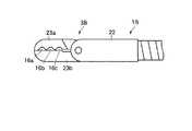
つぎに、第3の実施の形態について、図面にもとづいて説明する。図6は内視鏡用処置具1Bの先端の外観図である。ここでは、処置部3Bを構成する一対の生検カップ23a,23bのうち、一方の生検カップ23aのみ図示しないリンク機構を介して回動自在に支持されている。これに対して他方の生検カップ23bは、スリーブ22の一部がそのまま延出され一体に形成される。したがって、他方の生検カップ23bは固定である。 Next, a third embodiment will be described with reference to the drawings. FIG. 6 is an external view of the distal end of the endoscope treatment tool 1B. Here, of the pair of
このような構成であれば、リンク機構が簡素化されるうえに、操作的には先に説明したものと何ら変りがない。そして、他方の生検カップ23bが固定になったので、処置部3Bは強度的に増大化する。 With such a configuration, the link mechanism is simplified and the operation is not different from that described above. And since the other biopsy cup 23b became fixed, the
なお、上述した実施例においてはそれぞれ3つの切欠き部16a,16b,16cを備えたが、これに限定されるものではなく、少なくとも1つの切欠き部を備えていればよい。
以上の各実施の形態において詳述した内視鏡用処置具1,1A,1Bは、本発明の趣旨を逸脱しない範囲で切欠き部の形状や、生検カップの構成等を任意に組合せて用いることが可能である。In the above-described embodiment, each of the three
The
つぎに、本発明の他の特徴的な技術事項を下記の通り付記する。
記
(付記項1) 体腔内に挿入される挿入部と、上記挿入部の先端に配置された、少なくとも一方が他方に対して旋回可能で開閉可能な、一対の生検カップからなる処置部と、上記処置部を開閉駆動する処置部開閉手段と、上記挿入部基端側から上記処置部材開閉手段を介して上記処置部材の開閉を操作する操作手段とを有する内視鏡用処置具において、上記生検カップには、互いが閉じたときに当接する当接面が形成され、上記生検カップの少なくとも一方の当接面に、上記生検カップが閉じたときに開口部が形成される切欠き部を、少なくとも1つ以上設けたことを特徴とする内視鏡用処置具。Next, other characteristic technical matters of the present invention are appended as follows.
Record
(Additional Item 1) An insertion portion that is inserted into a body cavity, and a treatment portion that is disposed at the distal end of the insertion portion and includes a pair of biopsy cups that can be pivoted at least one of the other with respect to the other. An endoscopic treatment tool comprising: a treatment portion opening / closing means for opening / closing the treatment portion; and an operation means for operating the treatment member to be opened / closed from the insertion portion proximal end side via the treatment member opening / closing means. The biopsy cup is formed with a contact surface that abuts when the biopsy cup is closed, and an opening is formed on at least one contact surface of the biopsy cup when the biopsy cup is closed. An endoscopic treatment instrument comprising at least one notch.
(付記項2) 上記切欠き部は、上記一対の生検カップのうち、一方の生検カップにのみ設けられていることを特徴とする、付記項1に記載の内視鏡用処置具。
(付記項3) 上記一対の生検カップのうち、一方の生検カップのみが上記挿入部先端に旋回可能に設けられ、他方の生検カップは上記挿入部先端に固定されることを特徴とする、付記項1および請求項2のいずれかに記載の内視鏡用処置具。(Additional Item 2) The endoscopic treatment tool according to
(Additional Item 3) Of the pair of biopsy cups, only one of the biopsy cups is pivotally provided at the distal end of the insertion portion, and the other biopsy cup is fixed to the distal end of the insertion portion. The endoscope treatment tool according to any one of
2…挿入部、5a,5b…生検カップ、3…処置部、6…リンク機構(処置部開閉手段)、14…操作ワイヤ(操作手段)、15…当接部、16a,16b,16c…切欠き部、17…刃付け部、20…歯部。 2 ... Insertion part, 5a, 5b ... Biopsy cup, 3 ... Treatment part, 6 ... Link mechanism (treatment part opening / closing means), 14 ... Operation wire (operation means), 15 ... Contact part, 16a, 16b, 16c ... Notch part, 17 ... Blade part, 20 ... Tooth part.
Claims (3)
Translated fromJapanese上記処置部を構成する一対の生検カップに設けられ、生検カップを互いに閉じた状態で互いに当接する当接部と、
少なくとも一方の生検カップの当接部に設けられ、閉じた状態の当接部を部分的に開口する少なくとも1つ以上の切欠き部と
を具備することを特徴とする内視鏡用処置具。An insertion portion to be inserted into a body cavity; a treatment portion including a pair of biopsy cups provided at a distal end of the insertion portion and pivotable with respect to the other; and a pair of biopsies constituting the treatment portion Endoscopic treatment provided with a treatment part opening / closing means for opening and closing the cup and an operation means for opening / closing the pair of biopsy cups by driving the treatment part opening / closing means from the proximal end side of the insertion part In the ingredients
A pair of biopsy cups constituting the treatment section, abutting portions that abut on each other in a state where the biopsy cups are closed;
An endoscopic treatment tool comprising: at least one notch portion provided at a contact portion of at least one biopsy cup and partially opening the contact portion in a closed state .
Priority Applications (1)
| Application Number | Priority Date | Filing Date | Title |
|---|---|---|---|
| JP2003398176AJP2005152463A (en) | 2003-11-27 | 2003-11-27 | Treating instrument for endoscope |
Applications Claiming Priority (1)
| Application Number | Priority Date | Filing Date | Title |
|---|---|---|---|
| JP2003398176AJP2005152463A (en) | 2003-11-27 | 2003-11-27 | Treating instrument for endoscope |
Publications (1)
| Publication Number | Publication Date |
|---|---|
| JP2005152463Atrue JP2005152463A (en) | 2005-06-16 |
Family
ID=34723095
Family Applications (1)
| Application Number | Title | Priority Date | Filing Date |
|---|---|---|---|
| JP2003398176AWithdrawnJP2005152463A (en) | 2003-11-27 | 2003-11-27 | Treating instrument for endoscope |
Country Status (1)
| Country | Link |
|---|---|
| JP (1) | JP2005152463A (en) |
Cited By (9)
| Publication number | Priority date | Publication date | Assignee | Title |
|---|---|---|---|---|
| EP1898775A4 (en)* | 2005-06-21 | 2009-08-19 | Traxtal Inc | System, method and apparatus for navigated therapy and diagnosis |
| US7722565B2 (en) | 2004-11-05 | 2010-05-25 | Traxtal, Inc. | Access system |
| US7751868B2 (en) | 2004-11-12 | 2010-07-06 | Philips Electronics Ltd | Integrated skin-mounted multifunction device for use in image-guided surgery |
| US7805269B2 (en) | 2004-11-12 | 2010-09-28 | Philips Electronics Ltd | Device and method for ensuring the accuracy of a tracking device in a volume |
| US8469993B2 (en) | 2003-06-18 | 2013-06-25 | Boston Scientific Scimed, Inc. | Endoscopic instruments |
| US8611983B2 (en) | 2005-01-18 | 2013-12-17 | Philips Electronics Ltd | Method and apparatus for guiding an instrument to a target in the lung |
| US9398892B2 (en) | 2005-06-21 | 2016-07-26 | Koninklijke Philips N.V. | Device and method for a trackable ultrasound |
| US9681857B2 (en) | 2003-06-18 | 2017-06-20 | Boston Scientific Scimed, Inc. | Endoscopic instruments and methods of manufacture |
| US10582879B2 (en) | 2004-02-17 | 2020-03-10 | Philips Electronics Ltd | Method and apparatus for registration, verification and referencing of internal organs |
- 2003
- 2003-11-27JPJP2003398176Apatent/JP2005152463A/ennot_activeWithdrawn
Cited By (10)
| Publication number | Priority date | Publication date | Assignee | Title |
|---|---|---|---|---|
| US8469993B2 (en) | 2003-06-18 | 2013-06-25 | Boston Scientific Scimed, Inc. | Endoscopic instruments |
| US9681857B2 (en) | 2003-06-18 | 2017-06-20 | Boston Scientific Scimed, Inc. | Endoscopic instruments and methods of manufacture |
| US10582879B2 (en) | 2004-02-17 | 2020-03-10 | Philips Electronics Ltd | Method and apparatus for registration, verification and referencing of internal organs |
| US7722565B2 (en) | 2004-11-05 | 2010-05-25 | Traxtal, Inc. | Access system |
| US7751868B2 (en) | 2004-11-12 | 2010-07-06 | Philips Electronics Ltd | Integrated skin-mounted multifunction device for use in image-guided surgery |
| US7805269B2 (en) | 2004-11-12 | 2010-09-28 | Philips Electronics Ltd | Device and method for ensuring the accuracy of a tracking device in a volume |
| US8611983B2 (en) | 2005-01-18 | 2013-12-17 | Philips Electronics Ltd | Method and apparatus for guiding an instrument to a target in the lung |
| EP1898775A4 (en)* | 2005-06-21 | 2009-08-19 | Traxtal Inc | System, method and apparatus for navigated therapy and diagnosis |
| US8632461B2 (en) | 2005-06-21 | 2014-01-21 | Koninklijke Philips N.V. | System, method and apparatus for navigated therapy and diagnosis |
| US9398892B2 (en) | 2005-06-21 | 2016-07-26 | Koninklijke Philips N.V. | Device and method for a trackable ultrasound |
Similar Documents
| Publication | Publication Date | Title |
|---|---|---|
| EP1221896B1 (en) | Biopsy jaw assembly | |
| US5893876A (en) | Colposcopic biopsy punch with removable multiple sample basket | |
| EP2883503B1 (en) | Treatment device for endoscope | |
| JP3634655B2 (en) | Endoscopic biopsy forceps | |
| JP5686448B2 (en) | Hair follicle unit removal device having a rotation holding member | |
| JP2002538875A (en) | Endoscope multiple specimen biopsy forceps | |
| JPH0755222B2 (en) | Treatment tool | |
| JPH0630942A (en) | Biopsy device | |
| JP2004154164A (en) | Multi-degree-of-freedom type treating instrument | |
| US7278971B2 (en) | Endoscopic multiple biopsy forceps with swing member | |
| JP2005152463A (en) | Treating instrument for endoscope | |
| JP5707575B2 (en) | Flexible endoscopic instrument and acupuncture forceps | |
| JP5246394B2 (en) | Clip, clip unit and clip device | |
| JP4175675B2 (en) | Continuous biopsy tool | |
| US20060084885A1 (en) | Endoscopic multiple biopsy forceps with swing member | |
| JP5775866B2 (en) | Medical instruments | |
| JP2005204998A (en) | Forceps for endoscope | |
| JP5363769B2 (en) | Surgical instrument | |
| JPH03139340A (en) | Treating implement for endoscope | |
| JP2002282265A (en) | Endoscope forceps | |
| JPH1176244A (en) | Treating device for endoscope | |
| AU2007202246A1 (en) | Medical device actuators | |
| JP4373536B2 (en) | Endoscopic biopsy forceps with needle | |
| JPH11299799A (en) | Forceps | |
| CN100594003C (en) | pliers |
Legal Events
| Date | Code | Title | Description |
|---|---|---|---|
| A300 | Withdrawal of application because of no request for examination | Free format text:JAPANESE INTERMEDIATE CODE: A300 Effective date:20070206 |