JP2005152187A - 3D ultrasonic phantom - Google Patents
3D ultrasonic phantomDownload PDFInfo
- Publication number
- JP2005152187A JP2005152187AJP2003393461AJP2003393461AJP2005152187AJP 2005152187 AJP2005152187 AJP 2005152187AJP 2003393461 AJP2003393461 AJP 2003393461AJP 2003393461 AJP2003393461 AJP 2003393461AJP 2005152187 AJP2005152187 AJP 2005152187A
- Authority
- JP
- Japan
- Prior art keywords
- ultrasonic
- dimensional
- phantom
- targets
- probe
- Prior art date
- Legal status (The legal status is an assumption and is not a legal conclusion. Google has not performed a legal analysis and makes no representation as to the accuracy of the status listed.)
- Pending
Links
Images

Landscapes
- Ultra Sonic Daignosis Equipment (AREA)
- Instructional Devices (AREA)
Abstract
Translated fromJapaneseDescription
Translated fromJapaneseこの発明は、超音波画像における患部位置の測定精度向上に係る技術であり、超音波画像データの座標系と位置センサ等の座標系を較正する超音波キャリブレーション装置、特にこのキャリブレーションで使用される治具である3次元超音波ファントムに関するものである。 The present invention relates to a technique for improving the measurement accuracy of an affected part position in an ultrasonic image, and is used in an ultrasonic calibration device that calibrates a coordinate system of ultrasonic image data and a coordinate system such as a position sensor, particularly in this calibration. The present invention relates to a three-dimensional ultrasonic phantom that is a jig.
従来の超音波キャリブレーション装置では、超音波診断装置から3次元データが取得できないため、例えば非特許文献1のFig.2に示されるように、超音波ファントム内に2本のラインターゲットを張り、その交点(参照点)が2次元超音波画像内に映るように2次元超音波プローブを操作している。また、その時のプローブの位置・姿勢を記録する。交点を複数の方向から撮影し、上記データを取得することで、キャリブレーション計算を正確に行っている。従来、本発明で提案するような3次元超音波ファントムは存在しなかった。 In the conventional ultrasonic calibration apparatus, three-dimensional data cannot be acquired from the ultrasonic diagnostic apparatus. For example, FIG. As shown in FIG. 2, two line targets are set in the ultrasonic phantom, and the two-dimensional ultrasonic probe is operated so that the intersection (reference point) is reflected in the two-dimensional ultrasonic image. Also record the position and orientation of the probe at that time. The intersection point is photographed from a plurality of directions and the above data is acquired, so that the calibration calculation is accurately performed. Conventionally, there has been no three-dimensional ultrasonic phantom as proposed in the present invention.
上述のような従来の超音波キャリブレーション装置では、ラインターゲットの交点(参照点)が2次元超音波画像内に映るようにプローブを操作することは困難である。また、複数の参照点の3次元座標データを、上記の困難なプローブ操作をして2次元画像を取得し、プローブの位置・姿勢データと合成して求めることは、計算誤差を生むという問題点があった。 In the conventional ultrasonic calibration apparatus as described above, it is difficult to operate the probe so that the intersection (reference point) of the line target is reflected in the two-dimensional ultrasonic image. In addition, obtaining the two-dimensional image of the three-dimensional coordinate data of a plurality of reference points by performing the above difficult probe operation and combining it with the probe position / posture data causes a calculation error. was there.
この発明に係る超音波キャリブレーション装置では、3次元超音波ファントムを提案する。この3次元超音波ファントムには、球ターゲットを所定の位置に取り付けるようにしたため、3次元超音波診断装置から得られる3次元データには複数の球ターゲットを映り込ませることができ、キャリブレーション計算に必要な複数の参照点データを困難なプローブ操作をせずに取得することができる。また、3次元超音波ファントム内の複数の球ターゲットは異なる径にし、また、球ターゲット間の距離も異なるようにしたため、プローブの位置・姿勢による影響を受けずに、得られた3次元超音波画像から、各々の球ターゲットの同定を容易にした。 In the ultrasonic calibration apparatus according to the present invention, a three-dimensional ultrasonic phantom is proposed. In this 3D ultrasonic phantom, a spherical target is attached at a predetermined position, so that a plurality of spherical targets can be reflected in the 3D data obtained from the 3D ultrasonic diagnostic apparatus, and the calibration calculation is performed. The plurality of reference point data necessary for the acquisition can be acquired without performing a difficult probe operation. In addition, since the plurality of spherical targets in the three-dimensional ultrasonic phantom have different diameters and the distances between the spherical targets are also different, the obtained three-dimensional ultrasonic wave is not affected by the position and orientation of the probe. From the image, identification of each sphere target was facilitated.
この発明の請求項1に記載の発明である3次元超音波ファントムは、超音波画像を用いた位置・姿勢のキャリブレーションにおいて使用されるものであって、筐体と、この筐体内に固定された複数個のターゲットと、上記筐体内に充填された組織等価剤とを備えたことを特徴とするものである。 The three-dimensional ultrasonic phantom according to the first aspect of the present invention is used in position / orientation calibration using an ultrasonic image, and is fixed to the casing and the casing. And a plurality of targets, and a tissue equivalent agent filled in the casing.
この発明の請求項2に記載の発明である3次元超音波ファントムは、請求項1に記載のものであって、複数個のターゲットが、それぞれ径の異なる球形であり、かつ、ターゲット相互の距離が異なるように筐体内に固定されていることを特徴とするものである。 A three-dimensional ultrasonic phantom according to a second aspect of the present invention is the three-dimensional ultrasonic phantom according to the first aspect, wherein the plurality of targets are spherical with different diameters, and the distance between the targets. It is characterized in that it is fixed in the housing so as to be different.
この発明によれば、複数の球ターゲットを埋め込んだ3次元超音波ファントムと、3次元超音波診断装置を用いたことにより、キャリブレーション計算に必要な参照点データが一度に複数取得できるようにした。また、プローブ位置・姿勢の計測を一度しか行わないため、計測誤差を減らすことを可能にした。また、径の異なる球ターゲット、および、球ターゲット間距離を異なるようにしたため、3次元超音波画像における各球ターゲットの同定を容易にする。 According to the present invention, by using a 3D ultrasonic phantom in which a plurality of sphere targets are embedded and a 3D ultrasonic diagnostic apparatus, a plurality of reference point data necessary for calibration calculation can be acquired at a time. . In addition, since the probe position / orientation is measured only once, the measurement error can be reduced. In addition, since the spherical targets having different diameters and the distance between the spherical targets are made different, identification of each spherical target in the three-dimensional ultrasonic image is facilitated.
実施の形態
図1は本発明の実施の形態による超音波キャリブレーション装置の構成図である。超音波キャリブレーション装置は、3次元超音波診断装置2と、超音波プローブ4と、3次元超音波ファントム6と、計算機8と、位置センサ10とを備えることを特徴とする。3次元超音波ファントム6上に配置した超音波プローブ4が3次元スキャンし、3次元超音波診断装置2から3次元超音波ファントム6の3次元超音波画像を取得する。同時に、位置センサ10からプローブ4の位置・姿勢データを取得する。計算機8は、3次元超音波画像、プローブ4の位置・姿勢データおよび3次元超音波ファントム6の設計データからキャリブレーション計算を行う。超音波プローブ4は、3次元スキャンを行うものである。位置センサ10は、対象物の3次元位置・姿勢データを取得するものであれば、機械式や光学式等の方式にはとらわれない。Embodiment FIG. 1 is a configuration diagram of an ultrasonic calibration apparatus according to an embodiment of the present invention. The ultrasonic calibration apparatus includes a three-dimensional ultrasonic
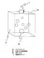
図2は本発明の実施の形態による3次元超音波ファントム6の構成図である。ファントムケース62内部に、複数の球ターゲット66を固定取り付けし、水等の組織等価剤64でファントムケース62を充填する。超音波プローブ4をファントムケース62に固定し、超音波スキャンにより超音波画像を取得する。ファントムケース62内部に複数の球ターゲット66を固定したため、1つの3次元超音波画像に複数の球ターゲット66の信号を含めることが可能となる。その結果、複数の球ターゲット66の位置データ(参照点データ)を得るために困難な超音波プローブ4の操作を不要としながら、1つの3次元超音波画像から複数の参照点データが得られる効果がある。 FIG. 2 is a configuration diagram of the three-dimensional ultrasonic phantom 6 according to the embodiment of the present invention. A plurality of
また、ターゲットの形状を球にすると、任意方向のプローブから取得した3次元超音波画像の任意断面は必ず円或は楕円形となり、半径或いは長径、短径が最大値となる断面での円或は楕円の中心が、3次元超音波画像での球ターゲットの中心位置となる。これにより、3次元超音波画像での球ターゲット位置の特定を容易化できる。 If the target shape is a sphere, the arbitrary cross section of the three-dimensional ultrasonic image acquired from the probe in an arbitrary direction is always a circle or an ellipse, and the circle or the cross section where the radius, the major axis, and the minor axis are maximum. The center of the ellipse is the center position of the sphere target in the three-dimensional ultrasonic image. Thereby, specification of the sphere target position in the three-dimensional ultrasonic image can be facilitated.
また、超音波プローブ4の位置・姿勢データは、上記3次元超音波画像の取得(スキャン)時に一度だけ記録すればよい。その結果、キャリブレーション計算量を減らすことが可能となり、更に、プローブ4の位置・姿勢データは一度しか計測しないため、計測誤差を抑えることが可能となる。また、複数の球ターゲット66の径を異なるようにすることで、3次元超音波画像内における各球ターゲット66の同定を容易にすることが可能となる。また、複数の球ターゲット66の配置において、球ターゲット66間の距離を異なるようにすることで、3次元超音波画像内における各球ターゲット66の同定を容易になる。 Further, the position / orientation data of the ultrasonic probe 4 may be recorded only once when the three-dimensional ultrasonic image is acquired (scanned). As a result, it is possible to reduce the amount of calibration calculation, and furthermore, since the position / posture data of the probe 4 is measured only once, measurement errors can be suppressed. In addition, by making the diameters of the plurality of sphere targets 66 different, it becomes possible to easily identify each
キャリブレーション計算では、最小2乗法等の最適化計算を行う。より安定した解を得るためには多くのデータ量が必要となるケースがある。その場合には、ターゲット数を増やすことで十分な参照点データを取得しても良い。或いは、超音波プローブ4の位置あるいは姿勢を変化させ、その時の超音波プローブ4の位置・姿勢を記録するのと同時に、スキャンした3次元超音波画像を取得し、上記超音波プローブ4の位置・姿勢データと合成して参照点データを増やしても同様の効果がある。特にターゲットが球ターゲット場合には、球ターゲット66の径を異なるサイズにする、あるいは、球ターゲット66間の距離を異なるようにしておけば同定が容易になる。 In the calibration calculation, optimization calculation such as the least square method is performed. There are cases where a large amount of data is required to obtain a more stable solution. In that case, sufficient reference point data may be acquired by increasing the number of targets. Alternatively, the position or posture of the ultrasonic probe 4 is changed, and the position and posture of the ultrasonic probe 4 at that time are recorded. At the same time, a scanned three-dimensional ultrasonic image is acquired, and the position and posture of the ultrasonic probe 4 are acquired. The same effect can be obtained by increasing the reference point data by combining with the posture data. In particular, when the target is a sphere target, identification can be facilitated by setting the diameter of the
この発明の3次元超音波ファントムは、超音波診断装置を用い患部位置を測定する際の測定治具に用いることができる。 The three-dimensional ultrasonic phantom of the present invention can be used as a measurement jig when measuring the position of an affected area using an ultrasonic diagnostic apparatus.
2 3次元超音波診断装置、 4 超音波プローブ、 6 3次元超音波ファントム、 8 制御用計算機、 10 位置センサ、 62 ファントムケース、 64 水或いは水等価樹脂等の組織等価剤、 66 球ターゲット。
2 3D ultrasonic diagnostic device, 4 ultrasonic probe, 6 3D ultrasonic phantom, 8 control computer, 10 position sensor, 62 phantom case, 64 tissue equivalent agent such as water or water equivalent resin, 66 ball target.
Claims (2)
Translated fromJapanese2. The three-dimensional ultrasonic phantom according to claim 1, wherein the plurality of targets have spherical shapes with different diameters and are fixed in the housing so that the distances between the targets are different.
Priority Applications (1)
| Application Number | Priority Date | Filing Date | Title |
|---|---|---|---|
| JP2003393461AJP2005152187A (en) | 2003-11-25 | 2003-11-25 | 3D ultrasonic phantom |
Applications Claiming Priority (1)
| Application Number | Priority Date | Filing Date | Title |
|---|---|---|---|
| JP2003393461AJP2005152187A (en) | 2003-11-25 | 2003-11-25 | 3D ultrasonic phantom |
Publications (1)
| Publication Number | Publication Date |
|---|---|
| JP2005152187Atrue JP2005152187A (en) | 2005-06-16 |
Family
ID=34719815
Family Applications (1)
| Application Number | Title | Priority Date | Filing Date |
|---|---|---|---|
| JP2003393461APendingJP2005152187A (en) | 2003-11-25 | 2003-11-25 | 3D ultrasonic phantom |
Country Status (1)
| Country | Link |
|---|---|
| JP (1) | JP2005152187A (en) |
Cited By (25)
| Publication number | Priority date | Publication date | Assignee | Title |
|---|---|---|---|---|
| JP2007117747A (en)* | 2005-10-28 | 2007-05-17 | Biosense Webster Inc | Target and method for calibration of ultrasound catheters |
| JP2011209691A (en)* | 2010-03-09 | 2011-10-20 | Canon Inc | Photoacoustic matching material and human tissue simulation material |
| JP2014228719A (en)* | 2013-05-23 | 2014-12-08 | キヤノン株式会社 | Phantom |
| KR20150043403A (en)* | 2012-08-10 | 2015-04-22 | 마우이 이미징, 인코포레이티드 | Calibration of Multiple Aperture Ultrasound Probes |
| US9339256B2 (en) | 2007-10-01 | 2016-05-17 | Maui Imaging, Inc. | Determining material stiffness using multiple aperture ultrasound |
| US9420994B2 (en) | 2006-10-25 | 2016-08-23 | Maui Imaging, Inc. | Method and apparatus to produce ultrasonic images using multiple apertures |
| US9510806B2 (en) | 2013-03-13 | 2016-12-06 | Maui Imaging, Inc. | Alignment of ultrasound transducer arrays and multiple aperture probe assembly |
| US9526475B2 (en) | 2006-09-14 | 2016-12-27 | Maui Imaging, Inc. | Point source transmission and speed-of-sound correction using multi-aperture ultrasound imaging |
| US9582876B2 (en) | 2006-02-06 | 2017-02-28 | Maui Imaging, Inc. | Method and apparatus to visualize the coronary arteries using ultrasound |
| WO2017036044A1 (en)* | 2015-09-01 | 2017-03-09 | 中国科学院深圳先进技术研究院 | Ultrasound probe calibration phantom, ultrasound probe calibration system and calibration method thereof |
| US9668714B2 (en) | 2010-04-14 | 2017-06-06 | Maui Imaging, Inc. | Systems and methods for improving ultrasound image quality by applying weighting factors |
| US9788813B2 (en) | 2010-10-13 | 2017-10-17 | Maui Imaging, Inc. | Multiple aperture probe internal apparatus and cable assemblies |
| US9883848B2 (en) | 2013-09-13 | 2018-02-06 | Maui Imaging, Inc. | Ultrasound imaging using apparent point-source transmit transducer |
| US9986969B2 (en) | 2012-09-06 | 2018-06-05 | Maui Imaging, Inc. | Ultrasound imaging system memory architecture |
| US10206662B2 (en) | 2009-04-14 | 2019-02-19 | Maui Imaging, Inc. | Calibration of ultrasound probes |
| US10226234B2 (en) | 2011-12-01 | 2019-03-12 | Maui Imaging, Inc. | Motion detection using ping-based and multiple aperture doppler ultrasound |
| CN109480902A (en)* | 2018-12-11 | 2019-03-19 | 中国科学院声学研究所 | A kind of imitated NDVI and its method measuring B ultrasound instrument pitching resolving power |
| CN109674489A (en)* | 2018-12-11 | 2019-04-26 | 中国科学院声学研究所 | A kind of imitated NDVI detecting medical supersonic instrument three-dimensional imaging performance |
| US10401493B2 (en) | 2014-08-18 | 2019-09-03 | Maui Imaging, Inc. | Network-based ultrasound imaging system |
| US10617384B2 (en) | 2011-12-29 | 2020-04-14 | Maui Imaging, Inc. | M-mode ultrasound imaging of arbitrary paths |
| US10835208B2 (en) | 2010-04-14 | 2020-11-17 | Maui Imaging, Inc. | Concave ultrasound transducers and 3D arrays |
| US10856846B2 (en) | 2016-01-27 | 2020-12-08 | Maui Imaging, Inc. | Ultrasound imaging with sparse array probes |
| KR20230062312A (en)* | 2021-10-29 | 2023-05-09 | 경북대학교 산학협력단 | Device and method for aligning the reference position of the shape restoration device |
| US12167209B2 (en) | 2012-09-06 | 2024-12-10 | Maui Imaging, Inc. | Ultrasound imaging system memory architecture |
| US12190627B2 (en) | 2015-03-30 | 2025-01-07 | Maui Imaging, Inc. | Ultrasound imaging systems and methods for detecting object motion |
- 2003
- 2003-11-25JPJP2003393461Apatent/JP2005152187A/enactivePending
Cited By (47)
| Publication number | Priority date | Publication date | Assignee | Title |
|---|---|---|---|---|
| JP2007117747A (en)* | 2005-10-28 | 2007-05-17 | Biosense Webster Inc | Target and method for calibration of ultrasound catheters |
| US9582876B2 (en) | 2006-02-06 | 2017-02-28 | Maui Imaging, Inc. | Method and apparatus to visualize the coronary arteries using ultrasound |
| US9986975B2 (en) | 2006-09-14 | 2018-06-05 | Maui Imaging, Inc. | Point source transmission and speed-of-sound correction using multi-aperture ultrasound imaging |
| US9526475B2 (en) | 2006-09-14 | 2016-12-27 | Maui Imaging, Inc. | Point source transmission and speed-of-sound correction using multi-aperture ultrasound imaging |
| US9420994B2 (en) | 2006-10-25 | 2016-08-23 | Maui Imaging, Inc. | Method and apparatus to produce ultrasonic images using multiple apertures |
| US10130333B2 (en) | 2006-10-25 | 2018-11-20 | Maui Imaging, Inc. | Method and apparatus to produce ultrasonic images using multiple apertures |
| US9339256B2 (en) | 2007-10-01 | 2016-05-17 | Maui Imaging, Inc. | Determining material stiffness using multiple aperture ultrasound |
| US10675000B2 (en) | 2007-10-01 | 2020-06-09 | Maui Imaging, Inc. | Determining material stiffness using multiple aperture ultrasound |
| US10206662B2 (en) | 2009-04-14 | 2019-02-19 | Maui Imaging, Inc. | Calibration of ultrasound probes |
| US11051791B2 (en)* | 2009-04-14 | 2021-07-06 | Maui Imaging, Inc. | Calibration of ultrasound probes |
| US11998395B2 (en) | 2010-02-18 | 2024-06-04 | Maui Imaging, Inc. | Point source transmission and speed-of-sound correction using multi-aperture ultrasound imaging |
| JP2011209691A (en)* | 2010-03-09 | 2011-10-20 | Canon Inc | Photoacoustic matching material and human tissue simulation material |
| US9668714B2 (en) | 2010-04-14 | 2017-06-06 | Maui Imaging, Inc. | Systems and methods for improving ultrasound image quality by applying weighting factors |
| US10835208B2 (en) | 2010-04-14 | 2020-11-17 | Maui Imaging, Inc. | Concave ultrasound transducers and 3D arrays |
| US11172911B2 (en) | 2010-04-14 | 2021-11-16 | Maui Imaging, Inc. | Systems and methods for improving ultrasound image quality by applying weighting factors |
| US9788813B2 (en) | 2010-10-13 | 2017-10-17 | Maui Imaging, Inc. | Multiple aperture probe internal apparatus and cable assemblies |
| US12350101B2 (en) | 2010-10-13 | 2025-07-08 | Maui Imaging, Inc. | Concave ultrasound transducers and 3D arrays |
| US10226234B2 (en) | 2011-12-01 | 2019-03-12 | Maui Imaging, Inc. | Motion detection using ping-based and multiple aperture doppler ultrasound |
| US10617384B2 (en) | 2011-12-29 | 2020-04-14 | Maui Imaging, Inc. | M-mode ultrasound imaging of arbitrary paths |
| US12343210B2 (en) | 2012-02-21 | 2025-07-01 | Maui Imaging, Inc. | Determining material stiffness using multiple aperture ultrasound |
| US12186133B2 (en) | 2012-03-26 | 2025-01-07 | Maui Imaging, Inc. | Systems and methods for improving ultrasound image quality by applying weighting factors |
| US12171621B2 (en) | 2012-08-10 | 2024-12-24 | Maui Imaging, Inc. | Calibration of multiple aperture ultrasound probes |
| US10064605B2 (en) | 2012-08-10 | 2018-09-04 | Maui Imaging, Inc. | Calibration of multiple aperture ultrasound probes |
| US11253233B2 (en) | 2012-08-10 | 2022-02-22 | Maui Imaging, Inc. | Calibration of multiple aperture ultrasound probes |
| US9572549B2 (en) | 2012-08-10 | 2017-02-21 | Maui Imaging, Inc. | Calibration of multiple aperture ultrasound probes |
| EP2883079A4 (en)* | 2012-08-10 | 2016-04-13 | Maui Imaging Inc | CALIBRATION OF ULTRASONIC PROBES WITH MULTIPLE OPENINGS |
| KR20150043403A (en)* | 2012-08-10 | 2015-04-22 | 마우이 이미징, 인코포레이티드 | Calibration of Multiple Aperture Ultrasound Probes |
| KR102176193B1 (en)* | 2012-08-10 | 2020-11-09 | 마우이 이미징, 인코포레이티드 | Calibration of Multiple Aperture Ultrasound Probes |
| US12167209B2 (en) | 2012-09-06 | 2024-12-10 | Maui Imaging, Inc. | Ultrasound imaging system memory architecture |
| US9986969B2 (en) | 2012-09-06 | 2018-06-05 | Maui Imaging, Inc. | Ultrasound imaging system memory architecture |
| US10267913B2 (en) | 2013-03-13 | 2019-04-23 | Maui Imaging, Inc. | Alignment of ultrasound transducer arrays and multiple aperture probe assembly |
| US9510806B2 (en) | 2013-03-13 | 2016-12-06 | Maui Imaging, Inc. | Alignment of ultrasound transducer arrays and multiple aperture probe assembly |
| JP2014228719A (en)* | 2013-05-23 | 2014-12-08 | キヤノン株式会社 | Phantom |
| US10653392B2 (en) | 2013-09-13 | 2020-05-19 | Maui Imaging, Inc. | Ultrasound imaging using apparent point-source transmit transducer |
| US12426855B2 (en) | 2013-09-13 | 2025-09-30 | Maui Imaging, Inc. | Ultrasound imaging using apparent point-source transmit transducer |
| US9883848B2 (en) | 2013-09-13 | 2018-02-06 | Maui Imaging, Inc. | Ultrasound imaging using apparent point-source transmit transducer |
| US12204023B2 (en) | 2014-08-18 | 2025-01-21 | Maui Imaging, Inc. | Network-based ultrasound imaging system |
| US10401493B2 (en) | 2014-08-18 | 2019-09-03 | Maui Imaging, Inc. | Network-based ultrasound imaging system |
| US12190627B2 (en) | 2015-03-30 | 2025-01-07 | Maui Imaging, Inc. | Ultrasound imaging systems and methods for detecting object motion |
| US10555724B2 (en) | 2015-09-01 | 2020-02-11 | Shenzhen Institutes Of Advanced Technology Chinese Academy Of Sciences | Ultrasound probe calibration phantom, ultrasound probe calibration system and calibration method thereof |
| WO2017036044A1 (en)* | 2015-09-01 | 2017-03-09 | 中国科学院深圳先进技术研究院 | Ultrasound probe calibration phantom, ultrasound probe calibration system and calibration method thereof |
| US12048587B2 (en) | 2016-01-27 | 2024-07-30 | Maui Imaging, Inc. | Ultrasound imaging with sparse array probes |
| US10856846B2 (en) | 2016-01-27 | 2020-12-08 | Maui Imaging, Inc. | Ultrasound imaging with sparse array probes |
| CN109480902A (en)* | 2018-12-11 | 2019-03-19 | 中国科学院声学研究所 | A kind of imitated NDVI and its method measuring B ultrasound instrument pitching resolving power |
| CN109674489A (en)* | 2018-12-11 | 2019-04-26 | 中国科学院声学研究所 | A kind of imitated NDVI detecting medical supersonic instrument three-dimensional imaging performance |
| KR102737170B1 (en)* | 2021-10-29 | 2024-12-03 | 경북대학교 산학협력단 | Device and method for aligning the reference position of the shape restoration device |
| KR20230062312A (en)* | 2021-10-29 | 2023-05-09 | 경북대학교 산학협력단 | Device and method for aligning the reference position of the shape restoration device |
Similar Documents
| Publication | Publication Date | Title |
|---|---|---|
| JP2005152187A (en) | 3D ultrasonic phantom | |
| CA2565520C (en) | Targets and methods for ultrasound catheter calibration | |
| US6311540B1 (en) | Calibration method and apparatus for calibrating position sensors on scanning transducers | |
| US9517049B2 (en) | Ultrasonic probe, position display apparatus and ultrasonic diagnostic apparatus | |
| CN108430334B (en) | Ultrasound imaging apparatus and ultrasound imaging method for examining volume of object | |
| CN104937409B (en) | Method and system for hand-guided ultrasound examination of an object | |
| CN109490830A (en) | Operating robot Locating System Accuracy detection method and detection device | |
| JP6718520B2 (en) | Ultrasonic diagnostic apparatus and method for controlling ultrasonic diagnostic apparatus | |
| CN110167447A (en) | System and method for the calibration of rapidly and automatically ultrasonic probe | |
| KR20170115446A (en) | Stand-alone type ultrasonic scanner | |
| JPWO2018051578A1 (en) | Ultrasonic diagnostic apparatus and control method of ultrasonic diagnostic apparatus | |
| US12048592B2 (en) | Three-dimensional ultrasound imaging support apparatus, three-dimensional ultrasound imaging support method, and three-dimensional ultrasound imaging support program | |
| CN100459941C (en) | Ultrasonic Image Diagnosis Device | |
| JP6865695B2 (en) | Ultrasound imaging device | |
| US8652047B2 (en) | Apparatus and method for automatically measuring the volume of urine in a bladder using ultrasound signals | |
| CN106456107B (en) | System and method for using ultrasound to be imaged | |
| JP6382031B2 (en) | Ultrasonic diagnostic apparatus and control program therefor | |
| KR102615722B1 (en) | Ultrasound scanner and method of guiding aim | |
| KR100875620B1 (en) | Ultrasound Imaging Systems and Methods | |
| WO2018051577A1 (en) | Ultrasonic diagnostic device and method for controlling ultrasonic diagnostic device | |
| JP4099196B2 (en) | Ultrasonic diagnostic equipment | |
| KR102512104B1 (en) | Apparatus and method for generating 3d ultrasound image | |
| JP2002330966A (en) | Ultrasonic diagnostic instrument | |
| TWI852356B (en) | Ultrasound imaging system | |
| JP4709611B2 (en) | Ultrasonic diagnostic equipment |
Legal Events
| Date | Code | Title | Description |
|---|---|---|---|
| A621 | Written request for application examination | Free format text:JAPANESE INTERMEDIATE CODE: A621 Effective date:20060116 | |
| A977 | Report on retrieval | Free format text:JAPANESE INTERMEDIATE CODE: A971007 Effective date:20081001 | |
| A131 | Notification of reasons for refusal | Effective date:20081007 Free format text:JAPANESE INTERMEDIATE CODE: A131 | |
| A521 | Written amendment | Free format text:JAPANESE INTERMEDIATE CODE: A523 Effective date:20081208 | |
| A131 | Notification of reasons for refusal | Free format text:JAPANESE INTERMEDIATE CODE: A131 Effective date:20090113 | |
| A02 | Decision of refusal | Effective date:20090609 Free format text:JAPANESE INTERMEDIATE CODE: A02 |