Movatterモバイル変換


[0]ホーム

URL:


JP2005151839A - Kernel storage device - Google Patents

Kernel storage device
Download PDF

Info

Publication number
JP2005151839A
JP2005151839AJP2003392481AJP2003392481AJP2005151839AJP 2005151839 AJP2005151839 AJP 2005151839AJP 2003392481 AJP2003392481 AJP 2003392481AJP 2003392481 AJP2003392481 AJP 2003392481AJP 2005151839 AJP2005151839 AJP 2005151839A
Authority
JP
Japan
Prior art keywords
grain
storage level
electrodes
detecting
capacitance
Prior art date
Legal status (The legal status is an assumption and is not a legal conclusion. Google has not performed a legal analysis and makes no representation as to the accuracy of the status listed.)
Pending
Application number
JP2003392481A
Other languages
Japanese (ja)
Inventor
Harumitsu Toki
治光 十亀
Current Assignee (The listed assignees may be inaccurate. Google has not performed a legal analysis and makes no representation or warranty as to the accuracy of the list.)
Iseki and Co Ltd
Iseki Agricultural Machinery Mfg Co Ltd
Original Assignee
Iseki and Co Ltd
Iseki Agricultural Machinery Mfg Co Ltd
Priority date (The priority date is an assumption and is not a legal conclusion. Google has not performed a legal analysis and makes no representation as to the accuracy of the date listed.)
Filing date
Publication date
Application filed by Iseki and Co Ltd, Iseki Agricultural Machinery Mfg Co LtdfiledCriticalIseki and Co Ltd
Priority to JP2003392481ApriorityCriticalpatent/JP2005151839A/en
Publication of JP2005151839ApublicationCriticalpatent/JP2005151839A/en
Pendinglegal-statusCriticalCurrent

Links

Images

Landscapes

Abstract

<P>PROBLEM TO BE SOLVED: To improve a bad condition that, in an apparatus for detecting a grain amount by detecting a storage level of grain by an electrostatic capacitance, when a pair of electrodes of the detecting apparatus is close to the inside wall surface of a grain storage tank, the electrostatic capacitance is abnormally changed and detection is not accurately performed. <P>SOLUTION: The grain storage apparatus has such constitution that a storage level detection means A for detecting the storage level of grain stored in the grain storage tank 1 by change of electrostatic capacitance by a pair of electrodes 2 is installed in the vertical direction at a spatial position apart from the inside wall surface 1a of the grain storage tank 1 by a fixed distance or more, the pair of the electrodes are fixed, respectively at a plurality of parts in the whole area in the vertical direction so as to keep their opposite distance 2a constant, an electrostatic capacitance detection part 3 for detecting the change of the electrostatic capacitance by an electronic circuit and a fixed position sensor 4 for detecting the fixed position of the storage level are installed and the electrostatic capacitance detection part 3 and the fixed position sensor 4 are arranged integrally with or closely to the proper positions of the electrodes 2. <P>COPYRIGHT: (C)2005,JPO&NCIPI

Description

Translated fromJapanese

本発明は、穀粒貯留装置に関し、穀粒貯留タンク内に貯留する穀粒量の貯留レベルを検出するもの等の分野に属する。  The present invention relates to a grain storage device, and belongs to the field of detecting a storage level of a grain amount stored in a grain storage tank.

穀粒を貯蔵するグレンタンク内の穀粒量を検出するものにおいて、このグレンタンクの内側壁面に上下方向に沿って一対の電極を配設し、この一対の電極によるグレンタンク内の穀粒量に比例して変化する静電容量により穀粒貯留レベルを検出すると共に、該一対の電極に対する電線接続用端子をグレンタンクの内側壁面を貫通して外部に突設させることを特徴とした穀粒量検出装置が開示されている。(例えば、特許文献1参照)
特開平10ー136769号
In what detects the amount of grain in the Glen tank that stores the grain, a pair of electrodes are arranged along the vertical direction on the inner wall surface of the Glen tank, and the amount of grain in the Glen tank by this pair of electrodes The grain storage level is detected by the capacitance that changes in proportion to the grain, and the terminal for wire connection to the pair of electrodes penetrates the inner wall surface of the Glen tank and protrudes outside. A quantity detection device is disclosed. (For example, see Patent Document 1)
JP-A-10-136769

しかし、該穀粒量検出装置の一対の電極とグレンタンクの内側壁面とが近接しているときは、この近接状態の影響を受けて一対の電極間の静電容量が異常変化するため的確な穀粒貯留レベルの検出が行われ難いという不具合があった。  However, when the pair of electrodes of the grain amount detection device and the inner wall surface of the grain tank are close to each other, the capacitance between the pair of electrodes changes abnormally due to the influence of the proximity state. There was a problem that it was difficult to detect the grain storage level.

そこで、このような一対の電極を、グレンタンクの内側壁面に対し近接状態となり悪影響を受けない所定距離以上離れた空間位置に配設して、安定して的確な穀粒貯留レベルの検出を行い得るよう不具合の改善を行うものである。  Therefore, such a pair of electrodes is placed in a spatial position at a predetermined distance or more away from the inner wall surface of the Glen tank so as not to be adversely affected, and stable and accurate grain storage level detection is performed. The problem is improved so as to obtain.

請求項1の発明は、穀粒貯留タンク1内に貯留する穀粒の貯留レベルを一対の電極2による静電容量の変化により検出する貯留レベル検出手段Aを、該穀粒貯留タンク1の内側壁面1aから所定距離以上離れた空間位置に上下方向に配設したことを特徴とする穀粒貯留装置の構成とする。  The first aspect of the present invention provides a storage level detection means A for detecting a storage level of a grain stored in the grain storage tank 1 by a change in electrostatic capacity of the pair ofelectrodes 2, inside the grain storage tank 1. It is set as the structure of the grain storage apparatus characterized by having arrange | positioned in the up-down direction in the space position away from thewall surface 1a more than predetermined distance.

このような構成により、請求項1の作用は、貯留レベル検出手段Aにおける板状又は丸状等適宜の形状及び長さを有する一対の電極2に対し、該穀粒貯留タンク1の内側壁面1aの距離が近い場合は、該電極2間において発生する静電容量が影響を受けて異常変化を起こし易いため、該内側壁面1aに対する電極2の立設位置を、静電容量の検出値が異常変化を起こさないだけの所定距離以上離れた空間位置に上下方向に配置させる。  With such a configuration, the action of claim 1 is theinner wall surface 1a of the grain storage tank 1 with respect to a pair ofelectrodes 2 having an appropriate shape and length such as a plate shape or a round shape in the storage level detection means A. When the distance between theelectrodes 2 is short, the capacitance generated between theelectrodes 2 is easily affected and an abnormal change is likely to occur. Therefore, the detection value of the capacitance is abnormal for the standing position of theelectrode 2 with respect to theinner wall surface 1a. It is arranged in a vertical direction at a spatial position separated by a predetermined distance or more that does not cause a change.

請求項2の発明は、前記貯留レベル検出手段Aの一対の電極2は、その対向距離2aを一定に保持するべく上下方向全域に亘り複数個所を各々固定したことを特徴とする請求項1記載の穀粒貯留装置の構成とする。  The invention according toclaim 2 is characterized in that the pair ofelectrodes 2 of the storage level detection means A are fixed at a plurality of positions over the entire vertical direction so as to keep theopposing distance 2a constant. It is set as the structure of the grain storage device.

このような構成により、請求項2の作用は、請求項1の作用とともに穀粒貯留タンク1内の空間位置に上下方向に長く対向配置している貯留レベル検出手段Aの電極2の対向距離2aを、一定して並行保持可能にその上部位置と下部位置及び中間部位置の少なくとも一個所以上を各々固定することにより、該対向距離2aが広がったり狭まったりして変化することがないから、該電極2の上下方向全域に亘る静電容量検出値の直線性が変動することがない。  With such a configuration, the action ofclaim 2 is theopposite distance 2a of theelectrode 2 of the storage level detection means A that is long and opposed to the spatial position in the grain storage tank 1 in the vertical direction together with the action of claim 1. By fixing each of at least one of the upper position, the lower position and the middle position so that they can be held in parallel in a constant manner, theopposing distance 2a does not change as it expands or narrows. The linearity of the capacitance detection value across the entire vertical direction of theelectrode 2 does not vary.

請求項3の発明は、前記貯留レベル検出手段Aの電極2による静電容量の変化を電子回路により検出する静電容量検出部3と、貯留レベルの一定位置を検出する定位置センサ4とを設けたことを特徴とする請求項1又は請求項2記載の穀粒貯留装置の構成とする。  The invention ofclaim 3 includes acapacitance detection unit 3 for detecting a change in capacitance due to theelectrode 2 of the storage level detection means A by an electronic circuit, and afixed position sensor 4 for detecting a fixed position of the storage level. It is set as the structure of the grain storage apparatus of Claim 1 orClaim 2 characterized by the above-mentioned.

このような構成により、請求項3の作用は、請求項1又は請求項2の作用とともに貯留レベル検出手段Aにおいて、穀粒貯留レベルの検出用として電子回路により形成される静電容量検出部3と、貯留レベルの一定位置検出用としての定位値センサ4とを設け、該静電容量検出部3による静電容量の検出値が穀粒の条件(例えば、品種,乾湿,選別等)の変化により変動することがあるから、貯留穀粒が空の状態と予め設定した一定位置の状態での静電容量の検出値から関係式を求め、この関係式により穀粒の貯留レベルを検出する。  With such a configuration, the action ofclaim 3 is the same as the action of claim 1 orclaim 2, and in the storage level detection means A, thecapacitance detection unit 3 formed by an electronic circuit for detecting the grain storage level. And alocalization value sensor 4 for detecting a fixed position of the storage level, and the capacitance detection value by thecapacitance detection unit 3 changes in grain conditions (for example, variety, dry and wet, selection, etc.) Therefore, a relational expression is obtained from the detected capacitance value in a state where the stored grain is empty and in a predetermined position, and the storage level of the grain is detected by this relational expression.

請求項4の発明は、前記静電容量検出部3と定位置センサ4とを、該電極2の適宜位置に一体的又は近接して配設したことを特徴とする請求項1又は請求項2又は請求項3記載の穀粒貯留装置の構成とする。  According to a fourth aspect of the present invention, thecapacitance detection unit 3 and thefixed position sensor 4 are disposed integrally or in proximity to an appropriate position of theelectrode 2. Or it is set as the structure of the grain storage apparatus ofClaim 3.

このような構成により、請求項4の作用は、請求項1又は請求項2又は請求項3の作用とともに貯留レベル検出手段Aにおいて、穀粒の貯留レベルを連続して検出する静電容量検出部3と一定位置を検出する定位値センサ4とを一体的に合体させるか又はジョイント等により近接接続させると共に、これらを何れか一方の電極2の対向裏面側の適宜位置に各々配置させる。  With such a configuration, the action ofclaim 4 is the capacitance detection unit that continuously detects the storage level of the grains in the storage level detection means A together with the action of claim 1,claim 2, orclaim 3. 3 and alocalization value sensor 4 for detecting a fixed position are integrally combined or connected in proximity by a joint or the like, and these are respectively arranged at appropriate positions on the opposite back side of one of theelectrodes 2.

請求項1の発明の効果は、穀粒貯留タンク1の内側壁面1aに対する貯留レベル検出手段Aの一対の電極2の立設位置を、静電容量の検出値が異常変化を起こさないだけの所定距離以上離れた空間位置に配置させることにより、該電極2の静電容量が他からの干渉を受けることがないから、該穀粒貯留タンク1内に貯留する穀粒の貯留レベルについて誤差の小さい検出を行わせることができる。  The effect of the invention of claim 1 is that the standing position of the pair ofelectrodes 2 of the storage level detection means A with respect to theinner wall surface 1a of the grain storage tank 1 is determined so that the detected value of capacitance does not cause an abnormal change. Since the capacitance of theelectrode 2 is not affected by interference by being disposed at a spatial position that is more than a distance away, there is little error in the storage level of the grains stored in the grain storage tank 1. Detection can be performed.

請求項2の発明の効果は、請求項1の効果とともに穀粒貯留タンク1内の空間位置に配置している貯留レベル検出手段Aの電極2の対向距離2aを、並行保持可能に上下方向の適宜位置を複数個所固定していることにより、該電極2の対向距離2aが広・狭に変化することがないから、静電容量の検出値が変動してその直線性が阻害されることがなく、該穀粒貯留タンク1内に貯留する穀粒の貯留レベルについて誤差の小さい検出を行わせることができる。  The effect of the invention ofclaim 2 is that, in addition to the effect of claim 1, theopposing distance 2a of theelectrode 2 of the storage level detection means A arranged at the spatial position in the grain storage tank 1 can be held in parallel in the vertical direction. By fixing a plurality of positions appropriately, the facingdistance 2a of theelectrode 2 does not change widely or narrowly, so that the detected capacitance value fluctuates and its linearity is hindered. In addition, detection with a small error can be performed for the storage level of the grains stored in the grain storage tank 1.

請求項3の発明の効果は、請求項1又は請求項2の効果とともに穀粒貯留タンク1内の穀粒の貯留レベルを検出する貯留レベル検出手段Aにおいて、静電容量検出部3による検出値が穀粒の条件等によって変動するため、この変動を定位値センサ4により検出した一定位置と貯留穀粒が空の状態との静電容量の検出値から関係式を求め、この関係式により貯留レベルを検出することができるから、該穀粒貯留タンク1内に貯留する穀粒の貯留レベルについて誤差の小さい検出を行わせることができる。  The effect of the invention ofclaim 3 is the detection value by thecapacitance detection unit 3 in the storage level detection means A that detects the storage level of the grain in the grain storage tank 1 together with the effect of claim 1 orclaim 2. Therefore, the relational expression is obtained from the capacitance detection value between the fixed position where the fluctuation is detected by thelocalization value sensor 4 and the stored grain is empty, and the storage is performed by this relational expression. Since the level can be detected, detection with a small error can be performed for the storage level of the grains stored in the grain storage tank 1.

請求項4の発明の効果は、請求項1又は請求項2又は請求項3の効果とともに、貯留レベル検出手段Aにおいて、穀粒の貯留レベルを検出する静電容量検出部3と定位値センサ4とを、一体的に合体させるか又はジョイント等により近接接続させて、該電極2の適宜位置に配置することにより、接続ハーネスの短縮化とハーネス接続用のコネクタの削減を可能にすることができるから、配線及びメンテナンスの簡略化と低コスト化を図ることができる。  The effect of the invention ofclaim 4 is that, together with the effect of claim 1 orclaim 2 orclaim 3, in the storage level detection means A, thecapacitance detection unit 3 and thelocalization value sensor 4 for detecting the storage level of the grain. Can be combined together or connected in proximity by a joint or the like, and disposed at an appropriate position of theelectrode 2, thereby making it possible to shorten the connection harness and reduce the harness connection connector. Therefore, simplification and cost reduction of wiring and maintenance can be achieved.

穀粒貯留タンク1内の穀粒の貯留レベルを一対の電極2による静電容量の変化により検出する貯留レベル検出手段Aを用いることによって、誤差の小さい貯留レベルの検出を実現することができる。  By using the storage level detection means A that detects the storage level of the grain in the grain storage tank 1 by the change in electrostatic capacity of the pair ofelectrodes 2, detection of the storage level with a small error can be realized.

以下に、この発明の実施例を図面に基づいて説明する。
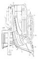
図1はコンバインの全体構成を示すもので、車台5の下部側に土壌面を走行する左右一対の走行クローラ6を張設した走行装置7を配設すると共に、該車台5上に、フィードチェン8に挟持して搬送供給される穀稈を脱穀処理した穀粒を選別回収して一時貯留する穀粒貯留タンク1と、このタンク1に貯留された穀粒を機外へ排出する排穀オーガ9を備えた脱穀装置10を載置配設し、この脱穀装置10の後端部に排藁処理装置11を装架して構成させる。
Embodiments of the present invention will be described below with reference to the drawings.
FIG. 1 shows the overall structure of a combine. A traveling device 7 is installed on a lower side of achassis 5 with a pair of left andright traveling crawlers 6 traveling on the soil surface. A grain storage tank 1 that selectively collects and recovers grains obtained by threshing grains that are sandwiched between 8 and transported, and a grain auger that discharges the grains stored in the tank 1 to the outside of the machine. Athreshing device 10 provided with 9 is placed and disposed, and a waste treatment device 11 is mounted on the rear end portion of thethreshing device 10 and configured.

該脱穀装置10の前方に、前端側から未刈穀稈を分草する分草体12と、分草した穀稈を引き起こす引起部13と、引き起こした穀稈を刈り取る刈刃部14と、刈り取った穀稈を掻き込むと共に搬送途上において扱深さを調節して該フィードチェン8へ引き継ぎを行う供給調節搬送部15等を有する刈取装置16を、刈取昇降シリンダ17により土壌面に対して昇降自在なるよう該車台5の前端部へ懸架配設して構成させる。  In front of thethreshing apparatus 10, aweeding body 12 for weeding uncut corn straw from the front end side, a pullingpart 13 for causing the chopped corn straw, acutting blade part 14 for cutting off the caused corn straw, and mowing Amowing device 16 having a feed adjusting and conveying section 15 and the like that scrapes the cereal and adjusts the depth of handling during transfer and takes over to the feed chain 8 can be raised and lowered with respect to the soil surface by the mowing lift cylinder 17. In this way, it is suspended from the front end portion of thechassis 5 and configured.

該刈取装置16の一側にコンバインの操作制御を行う操作装置18と、操作のための操作席19を設け、この操作席19の下方側にエンジン20を搭載し、後方側に前記穀粒貯留タンク1を配置すると共に、該操作装置18と操作席19を覆うキャビン21を設け、これら走行装置7,脱穀装置10,刈取装置16,操作装置18,エンジン20,キャビン21等によってコンバインの車体22を構成させる。  Anoperation device 18 for controlling the operation of the combine and anoperation seat 19 for operation are provided on one side of theharvesting device 16, anengine 20 is mounted on the lower side of theoperation seat 19, and the grain storage is provided on the rear side. The tank 1 is disposed and acabin 21 is provided to cover theoperation device 18 and theoperation seat 19. The traveling vehicle 7, thethreshing device 10, themowing device 16, theoperation device 18, theengine 20, thecabin 21, etc. Make up.

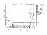
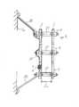
該穀粒貯留タンク1は、図2に示す如く、底部に沿って後方へ底部排穀螺旋23を延設し、この底部排穀螺旋23の後端部に、この底部排穀螺旋23によって穀粒貯留タンク1の底部から後側へ向けて排出される穀粒を機外へ排出させる排穀オーガ9を連設して構成させる。  As shown in FIG. 2, the grain storage tank 1 has abottom threshing helix 23 extending rearward along the bottom, and thebottom shed helix 23 has a grain at the rear end thereof. Agrain auger 9 that drains the grains discharged from the bottom of the grain storage tank 1 toward the rear side is provided continuously.

該排穀オーガ9は、穀粒貯留タンク1の後部外壁1bに固定した縦送り排出に方向変換する排穀ギヤケース24に、縦排穀螺旋25aを内装した縦排穀基筒25を該後部外壁1bに沿って鉛直方向で回動可能に支承して構成させる。  Thethreshing auger 9 has a vertical cereal base cylinder 25 with a vertical cereal helix spiral 25a installed in athreshing gear case 24 that changes the direction to vertical feed discharge fixed to the rear outer wall 1b of the grain storage tank 1, and the rear outer wall. It is supported and configured to be rotatable in the vertical direction along 1b.

該縦排穀基筒25の上端部を基部として、横排穀螺旋26aを内装した横排穀筒26を車体22の前後長に亘って配設すると共に、この横排穀筒26及び縦排穀基筒25による上下回動作用と左右旋回作用とにより、該穀粒貯留タンク1内の穀粒を機外へ排出可能に連動連結して構成させる。  With the upper end portion of the vertical threshing base cylinder 25 as a base, a horizontal threshingcylinder 26 having ahorizontal cereal helix 26 a is disposed over the longitudinal length of the vehicle body 22, and the horizontal threshingcylinder 26 and vertical exhaust The grains in the grain storage tank 1 are interlocked and connected so as to be discharged to the outside by the up-and-down turning action and the right-and-left turning action by the grain base 25.

図3に示す如く、該穀粒貯留タンク1内に貯留した穀粒の貯留レベルを静電容量の変化により検出する貯留レベル検出手段Aにおける一対の電極2を、静電容量が穀粒貯留タンク1の内側壁面1aの影響を受けて異常変化を起こし難い位置、つまり該内側壁面1aから所定距離以上離れた空間位置に相対状態で上下方向に延設して構成させる。  As shown in FIG. 3, the electrostatic capacity of the pair ofelectrodes 2 in the storage level detection means A that detects the storage level of the grain stored in the grain storage tank 1 by the change of the electrostatic capacity. 1 is configured to extend in the vertical direction in a relative state at a position where it is difficult to cause an abnormal change under the influence of theinner wall surface 1a, that is, at a spatial position separated from theinner wall surface 1a by a predetermined distance or more.

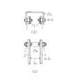
該貯留レベル検出手段Aにおける一対の電極2は、図4に示す如く、予め設定した最適の間隔を保つ対向距離2aを一定して並行保持すべく上部位置aと下部位置b及び中間部位置cとを、保持部材によって派生する静電容量の変化が小さい平面視U字状に形成した電極保持枠27によって各々螺子止め固定すると共に、上部位置aと下部位置bの片側と、該内側壁面1aの適宜位置とを各々電極支持アーム28により螺子止め連結して構成させる。  As shown in FIG. 4, the pair ofelectrodes 2 in the storage level detection means A has an upper position a, a lower position b, and an intermediate position c so as to maintain a constantopposing distance 2 a that keeps a preset optimum interval in parallel. Are screwed and fixed to each other by anelectrode holding frame 27 formed in a U shape in plan view with a small change in capacitance derived from the holding member, and one side of the upper position a and the lower position b and theinner wall surface 1a. These appropriate positions are screwed and connected by the electrode supportarms 28, respectively.

このように、該一対の電極2の対向横方向側d(開放側)に、予め設定した対向距離2aを保持するために使用する電極保持枠27が存在するときは、静電容量の直線性が低下するが(特に金属を用いるとその影響が大きい)、この電極保持枠27に派生する静電容量の変化が小さいジュラコン(絶縁材)等の部材を用いることにより、検出する穀粒の貯留レベルの直線性を保持することができる。  Thus, when theelectrode holding frame 27 used for holding the presetopposing distance 2a exists on the opposing lateral direction d (open side) of the pair ofelectrodes 2, the linearity of the capacitance Of the grain to be detected by using a member such as duracon (insulating material) whose capacitance change derived from theelectrode holding frame 27 is small. Level linearity can be maintained.

なお、別の電極保持枠27aとして、図5に示す如く、通電体の鉄板等により形成するもので、例えば、ゴム等による絶縁物iを介して一対の電極2を各々螺子止め固定して構成させる。  In addition, as anotherelectrode holding frame 27a, as shown in FIG. 5, it is formed of an iron plate or the like of a current-carrying body, and is configured by screwing and fixing a pair ofelectrodes 2 via an insulator i such as rubber, for example. Let

このように、該電極保持枠27,27aと一対の電極2とを絶縁した状態で固定することにより、ショート状態により静電容量の検出値が不正確となる不具合を防止できると共に、該電極保持枠27,27aを電極2端縁から離れるようU字状に形成しているから、静電容量の直線性の低下を抑制することができる。  In this way, by fixing the electrode holding frames 27 and 27a and the pair ofelectrodes 2 in an insulated state, it is possible to prevent a problem that the detection value of the capacitance becomes inaccurate due to a short-circuit state and to prevent the electrode holding. Since theframes 27 and 27a are formed in a U shape so as to be separated from the edge of theelectrode 2, it is possible to suppress a decrease in the linearity of the capacitance.

該貯留レベル検出手段Aにおける一対の電極2は、大型コンバインや乾燥機等においては1〜3メートルと長くなるため、該電極2の対向距離2aは中間部位置cにおいて最も広・狭に変位し易く、図6に示す如く、穀粒の貯留レベル検出値の直線性が悪くなり検出精度が低下するが、該電極2の上部位置aと下部位置b及び中間部位置cの少なくとも一個所以上を各々電極保持枠27により螺子止め固定しているから、対向距離2aを一定に並行保持でき検出精度の低下を防止することができる。  Since the pair ofelectrodes 2 in the storage level detection means A is as long as 1 to 3 meters in a large combine or a dryer, the opposingdistance 2a of theelectrodes 2 is displaced most widely or narrowly at the intermediate position c. As shown in FIG. 6, the linearity of the grain storage level detection value is deteriorated and the detection accuracy is lowered, but at least one of the upper position a, the lower position b, and the intermediate position c of theelectrode 2 is set. Since each of the electrode holding frames 27 is screwed and fixed, the facingdistance 2a can be held in parallel at a constant level, and a reduction in detection accuracy can be prevented.

該貯留レベル検出手段Aにおいて、該一対の電極2により穀粒の貯留レベルを静電容量により連続的に検出する静電容量検出部3の電子回路として、図7に示す如く、発振回路3aから一対の電極2へ、この電極2から整流回路3b及び平滑回路3c並びに増幅回路3dを経て、検出値の出力を行うべく接続して構成させる。  In the storage level detection means A, as shown in FIG. 7, anoscillation circuit 3a is used as an electronic circuit of thecapacitance detection unit 3 that continuously detects the storage level of the grains by the pair ofelectrodes 2. A pair ofelectrodes 2 are connected from thiselectrode 2 through arectifier circuit 3b, a smoothingcircuit 3c, and anamplifier circuit 3d so as to output a detection value.

なお、穀粒の貯留レベルの予め設定した一定位置を検出する、ON,OFFセンサ等による定位値センサ4を該静電容量検出部3へ接続すると共に、図8に示す如く、この定位値センサ4と静電容量検出部3とを一体的に組み込むか又は近接配置して構成させる。  Alocalization value sensor 4 such as an ON / OFF sensor that detects a predetermined position of the storage level of the grain is connected to thecapacitance detection unit 3 and, as shown in FIG. 4 and thecapacitance detection unit 3 are integrated or arranged close to each other.

このように、該静電容量検出部3と定位値センサ4とを一体化又は近接させることにより、接続ハーネス29の短縮化とハーネス接続用のコネクタ30の削減が可能となり、低コスト化を図ることができる。  In this way, by integrating or bringing thecapacitance detection unit 3 and thelocalization value sensor 4 together or close to each other, it is possible to shorten theconnection harness 29 and theharness connection connector 30, thereby reducing the cost. be able to.

該静電容量検出部3と定位値センサ4及び接続ハーネス29等を、図9に示す如く、片側の電極2の対向裏面側eの上下方向における適宜位置に取り付けると共に配線可能に構成させる。  As shown in FIG. 9, thecapacitance detection unit 3, thelocalization value sensor 4, theconnection harness 29, and the like are attached to appropriate positions in the vertical direction on the opposite back surface side e of theelectrode 2 on one side, and can be wired.

このように、該電極2の対向横方向側dに金属等障害物を存在させないことにより、静電容量の分布が乱れることがないから、静電容量の検出値の直線性が阻害されず検出値の出力を安定させることができる。なお、該電極2の検出表面側に該静電容量検出部3や定位値センサ4及び接続ハーネス29等を配置するときは、静電容量の直線性が低下し検出精度に影響を生じると共に、穀粒のブリッジ等が発生する要因ともなる。  As described above, since no obstacle such as metal exists on the opposite lateral side d of theelectrode 2, the capacitance distribution is not disturbed, and the linearity of the detected capacitance value is not hindered. The output of the value can be stabilized. When thecapacitance detection unit 3, thelocalization sensor 4, theconnection harness 29, and the like are arranged on the detection surface side of theelectrode 2, the linearity of the capacitance is reduced and the detection accuracy is affected. It also becomes a factor which the bridge | bridging etc. of a grain generate | occur | produces.

該貯留レベル検出手段Aにおける一対の電極2は、例えば、図10に示す如く、電極2の板幅と対向距離2aが5*5センチメートルの場合、電極2の対向裏面側eの方向は金属の影響を受け難いが、電極2の対向横方向側dは金属等障害物より30センチメートル以上離して取り付けることにより金属の影響を受け難くなり、安定して静電容量による穀粒貯留レベルの検出を行うことができる。  For example, as shown in FIG. 10, when the plate width of theelectrode 2 and theopposing distance 2a are 5 * 5 centimeters, the pair ofelectrodes 2 in the storage level detecting means A is in the direction of the opposing back surface side e of themetal 2 However, the opposing lateral side d of theelectrode 2 is less susceptible to metal by mounting it more than 30 centimeters away from obstacles such as metal, and stable grain storage level due to electrostatic capacity. Detection can be performed.

圃場における穀稈は刈取時期(水分)や品種等によって静電容量が異なるため、穀粒の状態に応じた穀粒の貯留レベルと静電容量検出部3による検出値との関係を求める必要があるが、この関係を求める際に、前記穀粒貯留タンク1への穀粒投入状態において予め設定した時間における静電容量検出部3の検出値を測定し、この検出値が変化しない場合を該電極2間に穀粒が存在しないと判断する基準点の一つとして設定構成させる。  Grain straws in the field have different electrostatic capacities depending on the harvesting time (moisture), varieties, etc., so it is necessary to determine the relationship between the storage level of the grains according to the state of the grains and the detection value by thecapacitance detection unit 3. However, when obtaining this relationship, the detection value of thecapacitance detection unit 3 is measured at a preset time in the grain input state to the grain storage tank 1, and the case where the detection value does not change is determined. It is set and configured as one of reference points for determining that there is no grain between theelectrodes 2.

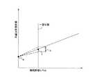
更に、穀粒の貯留レベルにおいて、該電極2の予め設定した一定位置に投入穀粒が達したことをONする前記定位値センサ4の作用を受けて静電容量検出部3により検出したときは、この検出値fと、前記の電極2間に穀粒が存在しないときの検出値gとにより、図11のフローチャート及び図12の線図に示す如く、両者の検出値f,gによる関係式(y=ax+b)を求めることが可能に構成させる。  Furthermore, at the storage level of the grain, when thecapacitance detecting unit 3 detects that the input grain has reached the preset fixed position of theelectrode 2 under the action of thelocalization value sensor 4 that is turned on. Based on the detected value f and the detected value g when no grain exists between theelectrodes 2, a relational expression based on the detected values f and g as shown in the flowchart of FIG. 11 and the diagram of FIG. (Y = ax + b) can be obtained.

このように、穀粒の貯留レベルと静電容量検出部3による検出値との関係式を求める際に必要となる基準点として、電極2間に穀粒が存在しないときの検出値gと、別の基準点としての貯留レベルの予め設定した一定位置の検出値fとを的確に求めることができるから、精度の高い貯留レベルと検出値の関係式を得ることにより、該穀粒貯留タンク1内に貯留する穀粒の貯留レベルについて誤差の小さい検出を行わせることができる。  Thus, as a reference point required when calculating the relational expression between the storage level of the grain and the detection value by thecapacitance detection unit 3, the detection value g when no grain exists between theelectrodes 2, Since the detection value f at a predetermined position of the storage level as another reference point can be accurately obtained, the grain storage tank 1 can be obtained by obtaining a highly accurate relational expression between the storage level and the detection value. The detection with a small error can be performed about the storage level of the grain stored in the inside.

該静電容量検出部3による静電容量の検出値は水分の誘電率が大きく穀粒水分の影響を受けやすいため、穀粒の貯留レベルの一定位置を該定位値センサ4と静電容量検出部3によって検出し、図13の線図に示す如く、このときの静電容量の値から静電容量検出部3の出力電圧により穀粒水分を算出し、この水分値によって貯留レベルの算出を可能とするよう構成させる。  The capacitance detection value by thecapacitance detection unit 3 has a large dielectric constant of moisture and is easily affected by grain moisture. Therefore, a fixed position of the grain storage level is detected by thelocalization value sensor 4 and the capacitance detection. As shown in the diagram of FIG. 13, the grain moisture is calculated from the capacitance value at this time based on the output voltage of thecapacitance detection unit 3, and the storage level is calculated based on the moisture value. Configure to be possible.

このように、一定位置の穀粒の貯留レベルを検出したときの静電容量により算出した穀粒水分値を加味して、貯留レベルを算出することが可能となるから、図14の線図に示す如く、水分の影響により変動する検出値の補正を行うことによって、該穀粒貯留タンク1内に貯留する穀粒の貯留レベルについて誤差の小さい検出を行わせることができる。  In this way, it is possible to calculate the storage level by taking into account the grain moisture value calculated by the capacitance when the storage level of the grain at a certain position is detected. As shown, by correcting the detection value that varies due to the influence of moisture, it is possible to perform detection with a small error with respect to the storage level of the grain stored in the grain storage tank 1.

なお、該穀粒貯留タンク1内に貯留する穀粒の排出毎に、次に投入された穀粒による貯留レベルと静電容量検出部3による検出値との関係式を新たに算出し、この算出式によって貯留レベルの検出を行うため、異なった圃場による穀粒水分の違い等の影響を受け難くすることができる。  In addition, every time the grain stored in the grain storage tank 1 is discharged, a relational expression between the storage level by the next input grain and the detection value by thecapacitance detection unit 3 is newly calculated. Since the storage level is detected by the calculation formula, it is difficult to be affected by the difference in grain moisture between different fields.

前記の如く、穀粒の貯留レベルと静電容量検出部3による検出値との関係を求めることができるまでは貯留レベルを求めることができないため、該穀粒貯留タンク1内に貯留する穀粒の排出後において、新たに貯留レベルが一定位置に達するまでの間は、図15に示す如く、過去の情報としてメモリに記憶させたf又はf,g点或いは関連直線等を基に貯留レベルの算出を行うよう構成させる。  As described above, since the storage level cannot be obtained until the relationship between the storage level of the grain and the detection value by thecapacitance detection unit 3 can be obtained, the grain stored in the grain storage tank 1 15 until the storage level newly reaches a certain position, the storage level is stored based on f or f, g points or related straight lines stored in the memory as past information as shown in FIG. Configure to perform the calculation.

このように、貯留レベルが一定位置に達するまでは過去の情報を基に早期モニタを行うことにより、その間多少の誤差hが生じても穀粒量が少ないことと、貯留レベルが一定位置に達したときは、新たに関係式を算出して誤差の小さい貯留レベルの検出が行えるから、作業者の不安を解消するために合理的な貯留レベルの検出を行うことができる。  In this way, by performing early monitoring based on past information until the storage level reaches a certain position, even if some error h occurs during that time, the amount of grain is small, and the storage level reaches a certain position. In this case, since a new relational expression is calculated and a storage level with a small error can be detected, a reasonable storage level can be detected in order to eliminate the operator's anxiety.

前記の如く、該電極2間に穀粒が存在しない場合においても空気の静電容量を検出(オフセット電圧)するが、この検出値は、素子のバラツキや発振周波数によって変化を受け易く、穀粒検出レベルの精度に影響を与えることになるため、図16に示す如く、前記静電容量検出部3の増幅回路3dにオフセット調節回路3eを追加接続して構成させる。  As described above, the capacitance of air is detected (offset voltage) even when there is no grain between theelectrodes 2, but this detected value is easily changed by the variation of elements and the oscillation frequency. Since the accuracy of the detection level is affected, as shown in FIG. 16, an offsetadjustment circuit 3e is additionally connected to theamplification circuit 3d of thecapacitance detection unit 3.

このように、該静電容量検出部3の増幅回路3dにオフセット調節回路3eを追加接続することにより、このオフセット調節回路3eによりオフセット電圧を予め設定した値に調節することができるから、穀粒の貯留レベルについて安定して誤差の小さい検出を行わせることができる。  In this way, by additionally connecting the offsetadjustment circuit 3e to theamplifier circuit 3d of thecapacitance detection unit 3, the offset voltage can be adjusted to a preset value by the offsetadjustment circuit 3e. Thus, it is possible to stably detect the storage level with a small error.

該静電容量検出部3により静電容量の変化を用いて穀粒の貯留レベルを検出する方式において、図17の線図に示す如く、貯留レベルと静電容量検出部3による検出電圧の関係式(y=ax+b)の一次係数の大きさによって検出信号線の傾きが変化するから、この現象を利用して穀粒水分の推定や穀粒の濡れを判定できるため、該静電容量検出部3をコストアップさせることなく高機能化を図ることができる。  In the method in which thecapacitance detection unit 3 detects the storage level of the grain using the change in capacitance, the relationship between the storage level and the detection voltage by thecapacitance detection unit 3 as shown in the diagram of FIG. Since the slope of the detection signal line changes depending on the magnitude of the first-order coefficient of the equation (y = ax + b), this phenomenon can be used to estimate grain moisture and determine grain wetting. 3 can be enhanced without increasing the cost.

穀粒以外のあらゆる粉体等の貯留タンクにも利用することができる。  It can also be used in storage tanks for all powders other than grains.

コンバインにおける全体構成を示す側面図。The side view which shows the whole structure in a combine.コンバインの穀粒貯留タンクと排穀オーガの構成状態を示す正面図。The front view which shows the structure state of the grain storage tank of a combine, and a grain reduction auger.穀粒貯留タンク内に貯留レベル検出手段の電極を配置した状態を示す正面図。The front view which shows the state which has arrange | positioned the electrode of the storage level detection means in a grain storage tank.(a)貯留レベル検出手段の一対の電極を絶縁保持した状態を示す平面図。(A) The top view which shows the state which hold | maintained insulation of a pair of electrode of the storage level detection means.

(b)貯留レベル検出手段の一対の電極を絶縁保持した状態を示す側面図。
(a)貯留レベル検出手段の一対の電極を絶縁保持した状態を示す平面図。 (b)貯留レベル検出手段の一対の電極を絶縁保持した状態を示す側面図。電極の対向距離の変化により静電容量検出値の直線性の歪み状態を示す線図。穀粒の貯留レベルを検出する静電容量検出部の電子回路を示すブロック図。静電容量検出部と定位値センサを一体的又は近接配置した状態を示す側面図。静電容量検出部関係の部材を電極の対向裏面側へ配置した状態を示す側面図。一対の電極の板幅と対向距離による金属に対する影響状態を示す作用図。電極間の空検出値と一定位置検出値により関係式を求めるフローチャート。電極間の空検出値と一定位置検出値により求める関係式の状態を示す線図。貯留レベルの一定位置検出時の静電容量値と穀粒水分との関係を示す線図。穀粒水分による穀粒貯留レベルと静電容量検出部の電圧の関係を示す線図。メモリに記憶させた情報を基に算出する貯留レベルの誤差状態を示す線図。静電容量検出部の増幅回路にオフセット調節回路の追加を示すブロック図。穀粒貯留レベルと静電容量検出部の電圧とによる穀粒の水分値を示す線図。
(B) The side view which shows the state which hold | maintained insulation of a pair of electrode of the storage level detection means.
(A) The top view which shows the state which hold | maintained insulation of a pair of electrode of the storage level detection means. (B) The side view which shows the state which hold | maintained insulation of a pair of electrode of the storage level detection means. The diagram which shows the distortion state of the linearity of an electrostatic capacitance detection value by the change of the opposing distance of an electrode. The block diagram which shows the electronic circuit of the electrostatic capacitance detection part which detects the storage level of a grain. The side view which shows the state which arranged the electrostatic capacitance detection part and the localization value sensor integrally or in proximity. The side view which shows the state which has arrange | positioned the member regarding an electrostatic capacitance detection part to the opposing back surface side of an electrode. The action figure which shows the influence state with respect to the metal by the plate | board width of a pair of electrode, and opposing distance. The flowchart which calculates | requires a relational expression with the empty detection value between electrodes, and a fixed position detection value. The diagram which shows the state of the relational expression calculated | required by the empty detection value between electrodes, and a fixed position detection value. The diagram which shows the relationship between the electrostatic capacitance value at the time of the fixed position detection of a storage level, and grain moisture. The diagram which shows the relationship between the grain storage level by grain moisture, and the voltage of an electrostatic capacitance detection part. The diagram which shows the error state of the storage level calculated based on the information memorize | stored in memory. The block diagram which shows addition of an offset adjustment circuit to the amplifier circuit of an electrostatic capacitance detection part. The diagram which shows the moisture value of the grain by a grain storage level and the voltage of an electrostatic capacitance detection part.

符号の説明Explanation of symbols

1. 穀粒貯留タンク
1a.内側壁面
2. 電極
2a.対向距離
3. 静電容量検出部
4. 定位値センサ
A. 貯留レベル検出手段
1.Grain storage tank 1a.Inner wall surface 2. Electrode 2a. 2. Opposite distanceCapacitance detection unit 4. Localization sensor A. Storage level detection means

Claims (4)

Translated fromJapanese
穀粒貯留タンク1内に貯留する穀粒の貯留レベルを一対の電極2による静電容量の変化により検出する貯留レベル検出手段Aを、該穀粒貯留タンク1の内側壁面1aから所定距離以上離れた空間位置に上下方向に配設したことを特徴とする穀粒貯留装置。  The storage level detection means A for detecting the storage level of the grains stored in the grain storage tank 1 by the change in capacitance by the pair of electrodes 2 is separated from the inner wall surface 1a of the grain storage tank 1 by a predetermined distance or more. The grain storage device characterized by being arranged in the vertical direction at a certain space position. 前記貯留レベル検出手段Aの一対の電極2は、その対向距離2aを一定に保持するべく上下方向全域に亘り複数個所を各々固定したことを特徴とする請求項1記載の穀粒貯留装置。  2. The grain storage device according to claim 1, wherein the pair of electrodes 2 of the storage level detection means A are fixed at a plurality of locations over the entire vertical direction so as to keep the opposing distance 2a constant. 前記貯留レベル検出手段Aの電極2における静電容量の変化を電子回路により検出する静電容量検出部3と、貯留レベルの一定位置を検出する定位置センサ4とを設けたことを特徴とする請求項1又は請求項2記載の穀粒貯留装置。  An electrostatic capacity detector 3 for detecting a change in electrostatic capacity of the electrode 2 of the storage level detection means A by an electronic circuit and a fixed position sensor 4 for detecting a fixed position of the storage level are provided. The grain storage device according to claim 1 or 2. 前記静電容量検出部3と定位置センサ4とを、該電極2の適宜位置に一体的又は近接して配設したことを特徴とする請求項1又は請求項2又は請求項3記載の穀粒貯留装置。  The grain according to claim 1, 2 or 3, wherein the capacitance detection unit 3 and the fixed position sensor 4 are disposed integrally or in close proximity to an appropriate position of the electrode 2. Grain storage device.
JP2003392481A2003-11-212003-11-21 Kernel storage devicePendingJP2005151839A (en)

Priority Applications (1)

Application NumberPriority DateFiling DateTitle
JP2003392481AJP2005151839A (en)2003-11-212003-11-21 Kernel storage device

Applications Claiming Priority (1)

Application NumberPriority DateFiling DateTitle
JP2003392481AJP2005151839A (en)2003-11-212003-11-21 Kernel storage device

Publications (1)

Publication NumberPublication Date
JP2005151839Atrue JP2005151839A (en)2005-06-16

Family

ID=34719169

Family Applications (1)

Application NumberTitlePriority DateFiling Date
JP2003392481APendingJP2005151839A (en)2003-11-212003-11-21 Kernel storage device

Country Status (1)

CountryLink
JP (1)JP2005151839A (en)

Similar Documents

PublicationPublication DateTitle
EP2927675B1 (en)Agricultural moisture sensor with coplanar electrodes
US9714856B2 (en)Automatic compensation for the effect of grain properties on mass flow sensor calibration
US6437582B1 (en)Device for the measurement of moisture of harvested crop
US6060889A (en)Sensing water and moisture using a delay line
CN100401024C (en) Water level sensor
US9844184B2 (en)Header position sensing system for an agricultural harvester
KR100280900B1 (en) Weighing device
EP2883043B1 (en)Grain bin capacitive moisture sensor system and method
US4168466A (en)Moisture tester
BR102015015313B1 (en) method and apparatus for calibrating a mass flow sensor during grain harvest
US20180073908A1 (en)Calibration-free continuous bin level sensor
EP3148312B1 (en)Sensor arrangement for combine harvester
CN105474003A (en)Gas concentration detection device
US8671741B2 (en)Extendable moisture content sensing system
US20030199291A1 (en)Apparatus and method for determining grain loss in combine harvesters
US9664631B2 (en)Moisture sensor for a forage harvester
US20230060670A1 (en)Capacitive parameter measurement in a self-propelled forage harvester
JP6494344B2 (en) Combine
JP2005151839A (en) Kernel storage device
KR102832388B1 (en) Combine, yield calculation method, yield calculation system, yield calculation program, and recording medium recording the yield calculation program, grain discharge quantity calculation method, grain discharge quantity calculation system, grain discharge quantity calculation program, and recording medium recording the grain discharge quantity calculation program, false inflow detection system, false inflow detection program, recording medium recording the false inflow detection program, and false inflow detection method, and reservoir level detection system
JP2018108092A (en)Harvester
US20230184575A1 (en)Systems and methods for detecting fill-levels in crop transport receptacles using capacitance-based sensor assemblies
JP2007082421A (en) Kernel storage detection device
JP2005257370A (en) Kernel storage level detector
JP6300591B2 (en) Harvesting machine

[8]ページ先頭

©2009-2025 Movatter.jp