JP2005149436A - Storage device, control method in storage device, job scheduling processing method, failure processing method, and program thereof - Google Patents
Storage device, control method in storage device, job scheduling processing method, failure processing method, and program thereofDownload PDFInfo
- Publication number
- JP2005149436A JP2005149436AJP2003390239AJP2003390239AJP2005149436AJP 2005149436 AJP2005149436 AJP 2005149436AJP 2003390239 AJP2003390239 AJP 2003390239AJP 2003390239 AJP2003390239 AJP 2003390239AJP 2005149436 AJP2005149436 AJP 2005149436A
- Authority
- JP
- Japan
- Prior art keywords
- priority
- job
- logical device
- host
- failure
- Prior art date
- Legal status (The legal status is an assumption and is not a legal conclusion. Google has not performed a legal analysis and makes no representation as to the accuracy of the status listed.)
- Pending
Links
Images


Classifications
- G—PHYSICS
- G06—COMPUTING OR CALCULATING; COUNTING
- G06F—ELECTRIC DIGITAL DATA PROCESSING
- G06F11/00—Error detection; Error correction; Monitoring
- G06F11/07—Responding to the occurrence of a fault, e.g. fault tolerance
- G06F11/14—Error detection or correction of the data by redundancy in operation
- G06F11/1402—Saving, restoring, recovering or retrying
- G06F11/1415—Saving, restoring, recovering or retrying at system level
- G06F11/1441—Resetting or repowering
- G—PHYSICS
- G06—COMPUTING OR CALCULATING; COUNTING
- G06F—ELECTRIC DIGITAL DATA PROCESSING
- G06F12/00—Accessing, addressing or allocating within memory systems or architectures
- G06F12/02—Addressing or allocation; Relocation
- G06F12/08—Addressing or allocation; Relocation in hierarchically structured memory systems, e.g. virtual memory systems
- G06F12/0802—Addressing of a memory level in which the access to the desired data or data block requires associative addressing means, e.g. caches
- G06F12/0804—Addressing of a memory level in which the access to the desired data or data block requires associative addressing means, e.g. caches with main memory updating
- G—PHYSICS
- G06—COMPUTING OR CALCULATING; COUNTING
- G06F—ELECTRIC DIGITAL DATA PROCESSING
- G06F12/00—Accessing, addressing or allocating within memory systems or architectures
- G06F12/02—Addressing or allocation; Relocation
- G06F12/08—Addressing or allocation; Relocation in hierarchically structured memory systems, e.g. virtual memory systems
- G06F12/0802—Addressing of a memory level in which the access to the desired data or data block requires associative addressing means, e.g. caches
- G06F12/0866—Addressing of a memory level in which the access to the desired data or data block requires associative addressing means, e.g. caches for peripheral storage systems, e.g. disk cache
- G06F12/0873—Mapping of cache memory to specific storage devices or parts thereof
- G—PHYSICS
- G06—COMPUTING OR CALCULATING; COUNTING
- G06F—ELECTRIC DIGITAL DATA PROCESSING
- G06F2212/00—Indexing scheme relating to accessing, addressing or allocation within memory systems or architectures
- G06F2212/26—Using a specific storage system architecture
- G06F2212/261—Storage comprising a plurality of storage devices
- G—PHYSICS
- G06—COMPUTING OR CALCULATING; COUNTING
- G06F—ELECTRIC DIGITAL DATA PROCESSING
- G06F3/00—Input arrangements for transferring data to be processed into a form capable of being handled by the computer; Output arrangements for transferring data from processing unit to output unit, e.g. interface arrangements
- G06F3/06—Digital input from, or digital output to, record carriers, e.g. RAID, emulated record carriers or networked record carriers
- G06F3/0601—Interfaces specially adapted for storage systems
- G06F3/0602—Interfaces specially adapted for storage systems specifically adapted to achieve a particular effect
- G06F3/061—Improving I/O performance
- G—PHYSICS
- G06—COMPUTING OR CALCULATING; COUNTING
- G06F—ELECTRIC DIGITAL DATA PROCESSING
- G06F3/00—Input arrangements for transferring data to be processed into a form capable of being handled by the computer; Output arrangements for transferring data from processing unit to output unit, e.g. interface arrangements
- G06F3/06—Digital input from, or digital output to, record carriers, e.g. RAID, emulated record carriers or networked record carriers
- G06F3/0601—Interfaces specially adapted for storage systems
- G06F3/0602—Interfaces specially adapted for storage systems specifically adapted to achieve a particular effect
- G06F3/0614—Improving the reliability of storage systems
- G06F3/0617—Improving the reliability of storage systems in relation to availability
- G—PHYSICS
- G06—COMPUTING OR CALCULATING; COUNTING
- G06F—ELECTRIC DIGITAL DATA PROCESSING
- G06F3/00—Input arrangements for transferring data to be processed into a form capable of being handled by the computer; Output arrangements for transferring data from processing unit to output unit, e.g. interface arrangements
- G06F3/06—Digital input from, or digital output to, record carriers, e.g. RAID, emulated record carriers or networked record carriers
- G06F3/0601—Interfaces specially adapted for storage systems
- G06F3/0628—Interfaces specially adapted for storage systems making use of a particular technique
- G06F3/0629—Configuration or reconfiguration of storage systems
- G06F3/0631—Configuration or reconfiguration of storage systems by allocating resources to storage systems
- G—PHYSICS
- G06—COMPUTING OR CALCULATING; COUNTING
- G06F—ELECTRIC DIGITAL DATA PROCESSING
- G06F3/00—Input arrangements for transferring data to be processed into a form capable of being handled by the computer; Output arrangements for transferring data from processing unit to output unit, e.g. interface arrangements
- G06F3/06—Digital input from, or digital output to, record carriers, e.g. RAID, emulated record carriers or networked record carriers
- G06F3/0601—Interfaces specially adapted for storage systems
- G06F3/0668—Interfaces specially adapted for storage systems adopting a particular infrastructure
- G06F3/0671—In-line storage system
- G06F3/0683—Plurality of storage devices
- G06F3/0689—Disk arrays, e.g. RAID, JBOD
Landscapes
- Engineering & Computer Science (AREA)
- Theoretical Computer Science (AREA)
- Physics & Mathematics (AREA)
- General Engineering & Computer Science (AREA)
- General Physics & Mathematics (AREA)
- Quality & Reliability (AREA)
- Memory System Of A Hierarchy Structure (AREA)
Abstract
Translated fromJapaneseDescription
Translated fromJapanese本発明は、接続線によりディスク装置と接続され、更に相互結合網によりキャッシュメモリおよび共有メモリと結合され、ホストとのインターフェースであるポートを介して前記ホストとの間で取り交わす入出力要求を処理する制御装置を有するストレージ装置(計算機システム)、ストレージ装置における制御方法、ジョブスケジューリング処理方法及び障害処理方法並びにそれらのプログラムに関し、特に、障害発生時のデータ優先度制御技術に関する。 The present invention is connected to a disk device by a connection line, and further coupled to a cache memory and a shared memory by an interconnection network, and processes an input / output request exchanged with the host via a port which is an interface with the host. The present invention relates to a storage device (computer system) having a control device, a control method in the storage device, a job scheduling processing method, a failure processing method, and their programs, and in particular, to a data priority control technique when a failure occurs.
従来技術1としては、特開平11−167521号公報に記載された技術が知られている。この従来技術1には、コモンバス方式を採用することにより、システム構成(規模)に応じてホストアダプタ、記憶装置アダプタ等の各論理モジュールやキャッシュメモリ及びディスク装置を接続することでスケーラブルなシステムを実現することができるようにすると共に、各論理モジュール、ディスク装置及びコモンバスの多重化により、縮退運転と各論理モジュール及び記憶媒体の活線挿抜対応とを可能とし、無停止で保守することができる記憶システムが記載されている。 As the
上記従来技術1のように、ホストと大容量のディスク装置との間に介在し、両者の間のデータ転送を制御するディスク制御装置の多くは、転送されるデータの一時記憶機構としてのキャッシュメモリを備えている。しかし、このキャッシュメモリは揮発性のメモリのために、電力供給が停止すると格納されているデータが消失する。また、ディスク制御装置におけるキャッシュメモリのハードウェア故障により、データが消失する可能性もある。このようなデータ消失を回避するために、二重化されたキャッシュメモリを有し、書き込みデータを二重化されたキャッシュメモリに格納するディスク制御装置が知られている。しかしながら、キャッシュメモリに二重障害が発生した場合には、データは消失することになる。 As in the
さらに、上記従来技術1は、また、冗長化された電源を有し、いずれかの電源が故障しても、継続運転可能となっている。また、停電時にはディスク制御装置が有する予備電源によりキャッシュメモリ、共有メモリ上のデータの消失を回避することができる。電源故障および停電時にはキャッシュメモリ上のデータ保障のため、キャッシュメモリ上のダーティデータをディスク装置に反映する。 Furthermore, the
さらに、以後のホストからのライト要求に関しては、データ保障のために、ディスク装置にライトデータが書き込まれた後にホストに対してライト完了報告を行うライト処理である同期ライトを用いる。しかし、該同期ライトにはライトアフタと比べてホストへの応答性能が低いという課題がある。 Further, for subsequent write requests from the host, synchronous write, which is a write process for reporting the write completion to the host after the write data is written to the disk device, is used to ensure data. However, the synchronous write has a problem that the response performance to the host is lower than that of the write after.
また、従来技術2としては、特開2002−334049号公報に記載された技術が知られている。この従来技術2には、非同期リモートコピーを行う複数ホスト配下の記憶サブシステム内でのサイドファイル量の流入量制限をホストに対して設定した優先度に基づいて行い、重要度の低いデータがキャッシュメモリを圧迫するのを防ぐことが記載されている。 Further, as the
また、従来技術3としては、特開2003−6016号公報に記載された技術が知られている。この従来技術3には、非同期リモートコピーにおいて、論理ボリュームグループにコピーの優先度を付け、優先度の高い論理ボリュームグループのコピーを優先することが記載されている。 Further, as the
上記従来技術1においては、障害発生時に、キャッシュメモリ上のダーティデータが消失する恐れがある。また、電源障害に備えて予備電源を有し、キャッシュメモリ上のダーティデータの保全を行っている。また、キャッシュメモリの障害に備えて、キャッシュメモリおよびキャッシュメモリを管理するためのデータを保持する共有メモリを二重化している。 In the
しかしながら、上記従来技術1においては、停電が継続し予備電源が使用できなくなった場合、キャッシュメモリもしくは共有メモリに二重障害が発生した場合にはディスクに反映されていないデータはデータの重要度とは無関係に消失する課題を有していた。また、障害発生時にはデータ保障の観点から同期ライトを用いるために、ストレージの入出力処理全体としての性能低下が発生するという課題を有していた。 However, in the above
また、上記従来技術2および3は、障害発生時(電源障害やキャッシュメモリの障害)に関しては考慮されていないものである。 The
本発明の目的は、上記課題を解決すべく、障害発生時にキャッシュメモリ上のデータを速やかにディスク装置に退避し、優先度の高い重要なデータの消失を回避することができるストレージ装置、ストレージ装置における制御方法、ジョブスケジューリング処理方法及び障害処理方法並びにそれらのプログラムを提供することにある。 In order to solve the above problems, an object of the present invention is to provide a storage device and a storage device capable of quickly evacuating data in a cache memory to a disk device when a failure occurs and avoiding loss of important data with high priority Is to provide a control method, a job scheduling processing method, a failure processing method, and a program thereof.
ストレージ装置は、ホストとのインターフェースであるポートと、キャッシュメモリと、前記ポート、前記キャッシュメモリ及び共有メモリと接続線により接続される制御装置と、該制御装置に接続されるディスク装置とを備える。ストレージ装置はホストに提供する論理デバイスに対する第一の優先度情報を管理端末から受け付け、第一の優先度情報に従って、優先度の高い論理デバイスは優先度の低い論理デバイスよりも多くの物理デバイスを割り当てておき、障害発生時には前記キャッシュメモリ内に格納されている論理デバイスのデータをこの論理デバイスに対応付けられている複数の物理デバイスに格納するように制御する。 The storage device includes a port that is an interface with a host, a cache memory, a control device that is connected to the port, the cache memory, and the shared memory by connection lines, and a disk device that is connected to the control device. The storage apparatus accepts the first priority information for the logical device provided to the host from the management terminal, and according to the first priority information, the logical device with higher priority has more physical devices than the logical device with lower priority. When a failure occurs, the logical device data stored in the cache memory is controlled to be stored in a plurality of physical devices associated with the logical device.
本発明によれば、ストレージ装置に障害が発生した際に、ストレージ内のキャッシュメモリ上のダーティデータを速やかにディスク装置に反映することができ、優先度の高い重要なデータの消失を回避することができる。 According to the present invention, when a failure occurs in a storage device, dirty data in the cache memory in the storage can be quickly reflected in the disk device, and the loss of important data with high priority can be avoided. Can do.
また、本発明によれば、ストレージ装置に障害が発生した際に、優先度の高い重要な業務に関する性能低下を極力回避することができる。 Further, according to the present invention, when a failure occurs in the storage apparatus, it is possible to avoid performance degradation related to important business with high priority as much as possible.
以下、本発明に係る実施の形態を図面を用いて説明する。 Hereinafter, embodiments of the present invention will be described with reference to the drawings.
本発明の実施の形態は、キャッシュメモリ112上にあって、ディスク装置114に対して未反映なデータであるダーティデータを、ストレージ110に障害が発生した際に、速やかにディスク装置114に反映するために、論理デバイスの配置先の物理デバイスをあらかじめ最適にしておくものである。また、ストレージ110に障害が発生した際には、ストレージ110は、あらかじめストレージ管理者からの入力によって運用管理される管理端末140により論理デバイスに設定された優先度順にダーティデータをディスク装置114に反映する。さらに、ストレージ110に障害が発生した際には、ストレージ110は、あらかじめストレージ管理者からの入力によって運用管理される管理端末140により設定された優先度に基づきストレージ内のジョブをスケジューリングする。 In the embodiment of the present invention, dirty data that is on the
次に、図1から図26を参照して、本発明の実施の形態を説明する。 Next, an embodiment of the present invention will be described with reference to FIGS.
図1は本発明に係る計算機システム(ストレージ装置)1の一実施の形態を説明するものである。計算機システム1は、ホスト100、ストレージ110及び管理端末140を備えて構成される。ホスト100はストレージ110に対して入出力要求を行う。ストレージ110はホスト100からの入出力要求に対して、ストレージ110が保持するキャッシュメモリ112を介して、ディスク装置114に読み書きを行う。管理端末140はストレージ管理者からの入力を受付け、ストレージ110の運用管理を行う。 FIG. 1 explains an embodiment of a computer system (storage device) 1 according to the present invention. The
次に、ストレージ110の構成について説明する。ストレージ110は、チャネルアダプタ120、ディスクアダプタ130、相互結合網(接続線から構成される。)111、キャッシュメモリ112、共有メモリ113、ディスク装置114、接続線115、電源116、予備電源(バッテリ)117及び電力線118を備えて構成される。そして、ディスクアダプタ130とディスク装置114との間は、1つのディスクアダプタあるいは1つの相互結合網において障害が発生した時にもディスク装置114が使用できるように1つのディスク装置に2つのディスクアダプタ130が異なる相互結合網111で接続されている。 Next, the configuration of the
チャネルアダプタ120は、ホスト100とキャッシュメモリ112との間のデータ転送を制御する。ディスクアダプタ130は、キャッシュメモリ112とディスク装置114との間のデータ転送を制御する。キャッシュメモリ112はホスト100から受信したデータ、あるいは、ディスク装置114から読み取ったデータを一時的に蓄えるメモリである。通常、ホスト100からのライト要求時には、ホスト100への応答性能の向上を目的として、キャッシュメモリ112にデータが書き込まれた時点で、ホスト100にライトの完了報告を行うライトアフタ方式が用いられる。共有メモリ113は、全てのチャネルアダプタ120とディスクアダプタ130とが共有するメモリである。 The channel adapter 120 controls data transfer between the
ディスク装置114を用いたストレージ、特にRAID(Redundant Array of Independent Disks)などのディスクアレイを制御するストレージでは、実際に搭載した物理デバイスであるディスク装置114上に、ホスト100へ提供する論理デバイスの規定のデータ形式に従いデータを格納している。 In a storage using the
チャネルアダプタ120、ディスクアダプタ130、キャッシュメモリ112、共有メモリ113、電源116及び予備電源117は、障害対応のため二重化されている。チャネルアダプタ120は、ホスト100からポート121を介して入出力要求を受け、ホスト100とのデータの転送を制御する。ディスクアダプタ130は、ディスク装置114とのデータの転送を制御する。チャネルアダプタ120、ディスクアダプタ130は共に、データの転送をキャッシュメモリ112を介して行う。電源116および予備電源117は、電力線118を介して、チャネルアダプタ120、ディスクアダプタ130、キャッシュメモリ112、共有メモリ113及びディスク装置114に電力を供給する。キャッシュメモリ112は、ホスト100からの書込みデータ、ディスク装置114からの読み込みデータを一時的に蓄えるメモリである。通常、ホスト100からのライト要求時には、ホスト100への応答性能の向上を目的として、キャッシュメモリ112にデータが書き込まれた時点で、ホスト100にライトの完了報告を行うライトアフタ方式が用いられる。さらに、キャッシュメモリ112は、一定量に分割して管理されており、分割したキャッシュメモリをセグメントと呼ぶ。各セグメントの状態は、後述するセグメント管理テーブル6で管理される。共有メモリ113は、全てのチャネルアダプタ120とディスクアダプタ130とが共有するメモリである。そして、共有メモリ113には、キャッシュメモリ112上のデータを制御するための情報、チャネルアダプタ120上の制御プロセッサで動作するジョブを制御するための情報、ディスクアダプタ130上の制御プロセッサで動作するジョブを制御するための情報を含む。即ち、共有メモリ113には、図2に示すように、論理デバイス管理テーブル2、LUパス管理テーブル3、物理デバイス管理テーブル4、スロット管理テーブル5、セグメント管理テーブル6、チャネルジョブ管理テーブル7、ディスクジョブ管理テーブル8、ホスト管理テーブル9、アクセスパターン管理テーブル10、業務管理テーブル11及びスケジューリング管理テーブル12等の情報が記憶されることになる。 The
管理端末140は、PCなどのストレージ管理プログラム動作手段142〜145と、ストレージ管理者との入出力手段141を有し、論理デバイスに関する属性設定など、I/F146、119を介しての、ストレージ110の保守運用に関するストレージ管理者からのインターフェースとなる。 The
以上説明したように、ストレージ110は、ホスト100とのインターフェースであるポート121を有し、上記ホストとの間で取り交わす入出力要求を処理するチャネルアダプタ120及びディスクアダプタ130から構成される制御装置を有し、該制御装置120、130は接続線115によりディスク装置114と接続され、さらに相互結合網111によりキャッシュメモリ112及び共有メモリ113と結合され、ストレージ管理者より各種パラメータ(図14及び図15並びに図16、図17及び図18に示す論理デバイス定義処理及びLUパス定義処理並びに論理デバイス優先度定義処理、ホスト優先度定義処理及び業務優先度定義処理についての各種パラメータ)を受け付ける管理端末140とI/F119により接続し、該管理端末140で受け付けられた各種パラメータを管理テーブル2〜11として格納する共有メモリ113で構成される。 As described above, the
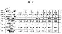
次に、論理デバイス管理テーブル2の一実施例について図3を用いて説明する。論理デバイス管理テーブル2は、論理デバイス番号201、サイズ202、デバイス状態203、物理デバイス番号204、接続ホスト番号205、ポート番号/ターゲットID/LUN206、論理デバイス優先度207、拡張論理デバイス情報208及び障害発生時データ退避情報209を含む。 Next, an example of the logical device management table 2 will be described with reference to FIG. The logical device management table 2 includes a logical device number 201, a
サイズ202には、当該論理デバイスの容量が格納される。例えば、図3では、論理デバイス番号1、2、…に関して、サイズに1GB、2GB、…を指定している。
デバイス状態203には、当該論理デバイスの状態を示す情報が設定される。状態としては、「オンライン」「オフライン」「未実装」「障害オフライン」が存在する。「オフライン」は、当該論理デバイスは定義され、正常に稼動しているが、LUパス未定義などでホスト100からのアクセスはできない状態にあることを示す。「未実装」は、当該論理デバイスが定義されておらずホスト100からのアクセスはできない状態にあることを示す。「障害オフライン」は、当該論理デバイスに障害が発生してホスト100からのアクセスができないことを示す。「オンライン」である論理デバイスに関して障害が検出された時点で、当該論理デバイスに関して「障害オフライン」が設定される。例えば、図3では、論理デバイス番号1、2、…に関して、デバイス状態に「オンライン」、「オンライン」、…を指定している。The
In the
物理デバイス番号204には、当該論理デバイスが対応する物理デバイス番号が格納される。例えば、図3では、論理デバイス番号1、2、…に関して、物理デバイス番号に1、2、…を指定している。
接続ホスト番号205は、当該論理デバイスにアクセスが許可されているホスト100を識別するホスト番号である。例えば、図3では、論理デバイス番号1、2、…に関して、接続ホスト番号に1、2、…を指定している。
エントリ206のポート番号には、当該論理デバイスが複数のポート121のどのポート121に接続されているかを表す情報が設定される。各ポート121には、ストレージ110内で一意な番号が割り振られており、当該論理デバイスがLUN定義されているポート121の番号が記録される。また、同エントリのターゲットIDとLUNは、論理デバイスを識別するための識別子である。ここでは、これらの識別子として、SCSI上でホスト100からデバイスをアクセスする場合に用いられるSCSI−ID、LUNが用いられる。例えば、図3では、論理デバイス番号1、2、…に関して、ポートIDに1、2、…、ターゲットID/LUNに0/0、0/0、…を指定している。
論理デバイス優先度207は、ストレージ110での障害発生時におけるデータの優先度を示す情報であり、例えば、最高優先度の値1から最低優先度の値5までの数値を用い、図3では、論理デバイス番号1、2、…に関して、論理デバイス優先度に1、5、…を指定している。
拡張論理デバイス情報208は、複数の論理デバイスを連結し、ひとつの論理デバイス(拡張論理デバイスと呼ぶ)としてホスト100に提供するための情報であり、拡張論理デバイスを使用する場合には、拡張論理デバイスを構成する論理デバイス番号のリストを指定し、拡張論理デバイスを使用しない場合には未定義を指定する。例えば、図3では、論理デバイス番号5は論理デバイス番号5、6、7から構成され、各論理デバイスのサイズの合計である12GBの論理デバイスとしてホスト100に提供される。
障害発生時データ退避情報209は、障害発生時において、各論理デバイスに関するキャッシュメモリ112上のダーティデータがディスク装置114に完全に退避されたかを管理するための情報である。状態としては、「未定義」「未完了」「完了」が存在する。「未定義」は、障害が発生していないことを示す。「未完了」は障害が発生しているが、キャッシュメモリ112上のダーティデータの退避が完了していないことを示す。「完了」は障害が発生しているが、キャッシュメモリ112上のダーティデータの退避が完了していることを示す。障害発生時データ退避情報209には、通常時は「未定義」が設定されているが、障害が検出された時点で、キャッシュメモリ112上にダーティデータを有する全ての論理デバイスに関して「未完了」が設定される。The physical device number 204 stores a physical device number corresponding to the logical device. For example, in FIG. 3, regarding the
The connected host number 205 is a host number that identifies the
In the port number of the
The
The extended logical device information 208 is information for connecting a plurality of logical devices and providing them to the
The
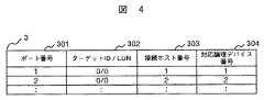
次に、LUパス管理テーブル3の一実施例について図4を用いて説明する。LUパス管理テーブル3は、ポート番号301、ターゲットID/LUN302、接続ホスト番号303、対応論理デバイス番号304を含む。ストレージ110内の各ポート121につき、有効なLUN分の情報を保持する。ターゲットID/LUN302は、ポート121に定義されたLUNのアドレスを格納する。接続ホスト番号303は、当該ポート121の当該LUNに対してアクセスを許可されているホスト100を示す情報である。一つの論理デバイスに対して複数ポート121のLUNが定義されている場合、それら全LUNの接続ホスト番号の和集合が論理デバイス管理情報2の接続ホスト番号205に保持される。対応論理デバイス番号304には、当該LUNを割り当てた論理デバイスの番号を格納する。例えば、図4では、ポート番号1、2、…に対して、ターゲットIDに0、LUNに0、接続ホスト番号に1、対応論理デバイス番号に1を指定している。 Next, an example of the LU path management table 3 will be described with reference to FIG. The LU path management table 3 includes a
次に、物理デバイス管理テーブル4の一実施例について図5を用いて説明する。物理デバイス管理テーブル4は、物理デバイス番号401、サイズ402、対応論理デバイス番号リスト403、デバイス状態404、RAID構成405、ディスク番号リスト406、ストライプサイズ407、ディスク内サイズ408、ディスク内開始オフセット409を含む。サイズ402には、物理デバイス番号401により特定される物理デバイスの容量が格納されている。対応論理デバイス番号リスト403には、当該物理デバイスが対応するストレージ110内の論理デバイス番号のリストが格納される。論理デバイスへ未割り当ての場合、当該エントリには無効値が設定される。デバイス状態404には、当該物理デバイスの状態を示す情報が設定される。状態としては、「オンライン」、「オフライン」、「未実装」、「障害オフライン」が存在する。「オンライン」は、当該物理デバイスが正常に稼動し、論理デバイスに割り当てられている状態であることを示す。「オフライン」は、当該物理デバイスは定義され、正常に稼動しているが、論理デバイスに未割り当てであることを示す。「未実装」は、当該物理デバイスがディスク装置114上に定義されていない状態にあることを示す。「障害オフライン」は、当該物理デバイスに障害が発生して論理デバイスに割り当てられないことを示す。なお、本実施形態では、簡単のため、物理デバイスは製品の工場出荷時にあらかじめディスク装置114上に作成されているものとする。このため、利用可能な物理デバイスについてはデバイス状態404の初期値は「オフライン」状態、その他は「未実装」状態となる。RAID構成405には、当該物理デバイスが割り当てられたディスク装置114のRAIDレベル、データディスクとパリティディスク数などRAID構成に関連する情報が保持される。同じように、ストライプサイズ407には、RAIDにおけるデータ分割単位(ストライプ)長が保持される。ディスク番号リスト406には、当該物理デバイスが割り当てられたRAIDを構成する複数のディスク装置114の番号が保持される。この番号はストレージ110内でディスク装置114を識別するために付与した一意な値である。ディスク内サイズ408とディスク内開始オフセット409には、当該物理デバイスデータが各ディスク装置114内のどの領域に割り当てられているかを示す情報である。本実施例では簡単のため、全物理デバイスについてRAIDを構成する各ディスク装置114内のオフセットとサイズを統一している。 Next, an example of the physical device management table 4 will be described with reference to FIG. The physical device management table 4 includes a
次に、スロット管理テーブル5の一実施例について図6を用いて説明する。ホスト100は、ストレージ110内の論理デバイスのデータを指定するために論理アドレスを使用する。論理アドレスは、例えば、論理デバイス番号と論理デバイス内の位置情報とからなる。ストレージ110内では、連続した論理アドレス空間を一定量に分割して管理しており、分割した論理アドレスをスロットと呼ぶ。論理アドレス空間の分割のサイズはスロットサイズとよぶ。例えば、スロット番号は、論理アドレス空間をスロットサイズで割った商に1を加算したものとする。スロット管理テーブル5はスロット番号501、セグメント番号リスト502、スロット属性503、論理デバイス番号504、ホスト番号505、ロック情報506を含む。セグメント番号リスト502には、当該スロットが含むセグメント(分割したキャッシュメモリ)のセグメント番号がリスト形式で保持される。例えば、図6では、ひとつのスロットが4つのセグメントから構成される例を示している。当該スロットの対応する位置のセグメントが存在しない場合、無効値として0を指定する。スロット属性503には、当該スロットの属性が保持される。属性としては「クリーン」「ダーティ」「フリー」が存在する。「クリーン」は当該スロットが保持するキャッシュメモリ112上のデータがディスク装置114上のデータと一致することを意味する。「ダーティ」は当該スロットが保持するキャッシュメモリ112上のデータがディスク装置114に未反映であることを意味する。「フリー」は当該スロットが使用されていないことを意味する。論理デバイス番号504には、当該スロットに対応する論理デバイス番号が保持される。ホスト番号505には、当該スロットに対応する入出力要求を行ったホスト100のホスト番号が保持される。ロック情報506には当該スロットのチャネルアダプタ120およディスクアダプタ130間での排他のためのロック情報が保持される。状態としては「オン」「オフ」が存在し、「オン」は当該スロットがロックされていることを意味し、「オフ」は当該スロットがロックされていないことを意味する。 Next, an example of the slot management table 5 will be described with reference to FIG. The
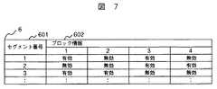
次に、セグメント管理テーブル6の一実施例について図7を用いて説明する。セグメント管理テーブル6は、セグメント番号601、ブロック情報602を含む。ブロック情報602は、ホスト100からのアクセスの単位(以下、ブロックよぶ)で、セグメントの当該位置に保持しているデータが有効か無効を示す。図7に示すセグメント管理テーブルの例では、セグメントサイズが2048バイト、ブロックサイズが512バイトの場合であり、セグメント管理テーブル6は4つのブロック情報をもち、セグメント番号1のブロック位置1とブロック位置3が有効、すなわち、セグメントの先頭から512バイト分と1024バイトから512バイト分に有効なデータがあることを示す。 Next, an example of the segment management table 6 will be described with reference to FIG. The segment management table 6 includes a
次に、チャネルジョブ管理テーブル7の一実施例について図8を用いて説明する。チャネルジョブとは、チャネルアダプタ120上で動作するジョブのことを指す。チャネルジョブ管理テーブル7は、ジョブ番号701、処理702、論理デバイス番号703、転送開始位置704、転送長705、ホスト番号706を含む。処理702には当該ジョブの処理内容が含まれる。処理内容には「リード」「ライト」が存在する。論理デバイス番号703は当該ジョブの処理対象となる論理デバイス番号を保持する。転送開始位置704は当該ジョブの処理対象となる論理デバイス上のアドレスを保持する。転送長705は当該ジョブの処理対象となるアクセス長を保持する。ホスト番号706は当該ジョブの処理に対応するホスト100のホスト番号が保持される。 Next, an embodiment of the channel job management table 7 will be described with reference to FIG. A channel job refers to a job that operates on the
次に、ディスクジョブ管理テーブル8の一実施例について図9を用いて説明する。ディスクジョブとは、ディスクアダプタ130上で動作するジョブのことを指す。ディスクジョブ管理テーブル8は、ジョブ番号801、処理802、論理デバイス番号803、転送開始位置804、転送長805、ホスト番号806、チャネルアダプタ番号807を含む。内容に関しては図8で述べたものと同様なものは、説明を省略する。チャネルアダプタ番号807には当該ジョブの要求元に対応するチャネルアダプタのチャネルアダプタ番号が保持される。 Next, an embodiment of the disk job management table 8 will be described with reference to FIG. The disk job refers to a job that operates on the
次に、ホスト管理テーブル9の一実施例について図10を用いて説明する。ホスト管理テーブル9は、ホスト番号901、ホスト名/WWN902、ホスト優先度903を含む。ホスト名/WWN902は、ホストを一意に識別するための情報である。ホスト優先度903は、ホスト100での入出力処理の重要度を反映するものであり、チャネルアダプタおよびディスクアダプタ上のジョブをスケジューリングする際の優先度として用いられる。優先度が高いジョブとは、例えば、無停止運転のオンライントランザクション処理なの高速な応答が要求される処理を行うジョブであり、また、優先度の低いジョブとは、例えば、夜間バッチ処理のような高速な応答が要求されない処理を行うジョブのことである。 Next, an example of the host management table 9 will be described with reference to FIG. The host management table 9 includes a
次に、アクセスパターン管理テーブル10の一実施例について図11を用いて説明する。アクセスパターン管理テーブル10は、論理デバイス番号1001、リード回数1002、ライト回数1003、リードヒット回数1004、ライトヒット回数1005、シーケンシャルリード回数1006、シーケンシャルライト回数1007を含む。リード回数1002は当該論理デバイスに対するリード回数を示す。ライト回数1003は当該論理デバイスに対するライト回数を示す。リードヒット回数1004は当該論理デバイスに対するリードヒット回数を示す。ライトヒット回数1005は当該論理デバイスに対するライトヒット回数を示す。シーケンシャルリード回数1006は当該論理デバイスに対するシーケンシャルリード回数を示す。シーケンシャルライト回数1007は当該論理デバイスに対するシーケンシャルライト回数を示す。ダーティ量管理情報1008は、各論理デバイスに関してキャッシュメモリ112上のダーティデータの量に関する情報を保持するものであり、例えば、ダーティデータ量の過去24時間の平均値、過去1時間の平均値、現在値を保持する。 Next, an embodiment of the access pattern management table 10 will be described with reference to FIG. The access pattern management table 10 includes a
次に、業務管理テーブル11の一実施例について図12を用いて説明する。本実施の形態において、業務とは、ホストと論理デバイスの組により定義される。一般的に言う業務は前記定義と規模が異なる場合があるが、本実施の形態では一例として前記定義のようにした。業務管理テーブル11は、業務番号1101、論理デバイス番号1102、ホスト番号1103、業務優先度1104を含む。論理デバイス番号1102、ホスト番号1103は業務に対応する論理デバイスとホストの組を示す。業務優先度1104は、ストレージ110での障害発生時におけるデータの優先度を示す情報であり、例えば、最高優先度の値1から最低優先度の値5までの数値を用いる。例えば、図12では、業務番号1に関して、論理デバイス番号に0、ホスト番号に0、業務優先度に1を指定している。本優先度に基づきチャネルアダプタおよびディスクアダプタ上のジョブのスケジューリングが行われる。ジョブの優先度の高さの意味の例はホスト管理テーブル9で説明したものと同様である。 Next, an embodiment of the business management table 11 will be described with reference to FIG. In the present embodiment, a business is defined by a set of a host and a logical device. Generally speaking, the business may have a different scale from the above definition, but in the present embodiment, the above definition is used as an example. The business management table 11 includes a
次に、スケジューリング管理テーブル12の一実施例について図13を用いて説明する。スケジューリング管理テーブル12は障害発生時ジョブスケジューリング時のスケジューリングパラメータを管理するものであり、論理デバイス優先度1201、ホスト優先度1202、業務優先度1203の3つの優先度に対して、スケジューリングの比率を指定する。本比率は後述するチャネルアダプタにおけるジョブスケジューリング処理(図20に示す処理)、チャネルアダプタにおけるジョブスケジューリング処理(図23に示す処理)に用いられる。例えば、図13では、論理デバイス優先度、ホスト優先度、業務優先度にそれぞれ、0.5、0.3、0.2の比率を設定しており、ジョブスケジューリング処理において、前記論理デバイス優先度は10回に5回の割合で使用される。 Next, an example of the scheduling management table 12 will be described with reference to FIG. The scheduling management table 12 manages scheduling parameters at the time of failure job scheduling, and designates scheduling ratios for the three priorities of the
次に、ストレージ管理者が管理端末ST(140)を用いて論理デバイス定義処理13及びLUパス定義処理14並びに論理デバイス優先度定義処理15、ホスト優先度定義処理16及び業務優先度定義処理17を行うことについて図14及び図15並びに図16、図17及び図18を用いて説明する。まず、ストレージ管理者が管理端末ST(140)を用いて論理デバイス定義処理13及びLUパス定義処理14を行うことによりホスト100はストレージS(110)内の論理デバイスにアクセスすることができるようになる。その後、ストレージ管理者が管理端末ST(140)を用いて論理デバイス優先度定義処理15、ホスト優先度定義処理16及び業務優先度定義処理17を行うことにより、ストレージS(110)は設定された各優先度(論理デバイス優先度、ホスト優先度及び業務優先度)に基づき適切に障害発生時の動作をすることが可能となる。以下、図中で、STは管理端末140、Sはストレージ110を表す。 Next, the storage administrator uses the management terminal ST (140) to perform the logical
まず、管理端末140を用いた論理デバイス定義処理の一実施例について図14を用いて説明する。論理デバイス定義処理13は、ストレージ管理者による管理端末140からの指示を受け付けて、ストレージ110が保持するディスク装置114に対して論理デバイスを定義する処理である。まず、管理端末140のCPU145は、ストレージ管理者より入力装置141やデイスプレイ142等を用いて入力された論理デバイスの定義(論理デバイス番号及び物理デバイス番号等)を受け付けてメモリ143等に記憶させる(ステップ1301)。その後、管理端末140のCPU145が、ストレージ管理者より、論理デバイスの定義として配置先の物理デバイス番号の指定の入力があったかを判定し(ステップ1302)、特別な理由があって配置先の物理デバイス番号の指定があった場合には、管理端末140のCPU145はそのままI/F146、119を介してストレージ110に対して論理デバイスの定義を指示する(ステップ1305)。管理端末140より指示を受け付けたストレージ110は、図3に示す論理デバイス管理テーブル2に論理デバイス番号、サイズ、デバイス状態、物理デバイス番号、開始アドレス、論理デバイス優先度を設定する。論理デバイス優先度207にはデフォルト値、例えば3を設定する。その後、管理端末140に完了報告を送信する(ステップ1306)。デバイス状態としては初期値である「オフライン」が設定される。最後に、管理端末140は、ストレージ110より完了報告を受け付ける(ステップ1307)。 First, an example of logical device definition processing using the
配置先の物理デバイス番号の指定がなかった場合には、管理端末140のCPU145は、共有メモリ113に記憶された図3に示す論理デバイス管理テーブル2及び図5に示す物理デバイス管理テーブル4の複製を管理端末140のメモリ143に格納し、該格納された情報を参照することにより(ステップ1303)、配置先の物理デバイスを決定し、ストレージ110に転送されて共有メモリ113内の論理デバイス管理テーブル2及び物理デバイス管理テーブル4に設定されることになる。具体的には、優先度が高い論理デバイスのキャッシュメモリ112上のデータを早急にディスク装置114に退避できるように、配置先の物理デバイスを決定し、ストレージ110に転送されて共有メモリ113内の論理デバイス管理テーブル2及び物理デバイス管理テーブル4に設定されることになる。決定方法としては、例えば、同一優先度の論理デバイスを異なる複数の物理デバイス(1又は複数のディスク装置114から構成される)に配置する。これにより、データ退避時に物理デバイスへのアクセス競合が起きず、高速なデータ退避が期待できる。また、別の決定方法としては、前述の拡張論理デバイスを用いることにより、一つの論理デバイスを複数の論理デバイスから構成する。このように各論理デバイスを配置する物理デバイスを分散させることにより、データ退避時に物理デバイスへのアクセス競合が起きず、高速なデータ退避が期待できる。その後、ストレージ管理者に対して管理端末140のディスプレイ142を介して論理デバイスの配置先として最適な(推奨する)物理デバイスを提示する(ステップ1304)。その後の処理は、ステップ1305以降と同様である。 When the physical device number of the placement destination is not specified, the
即ち、論理デバイス定義処理13は、管理端末140はホストに提供する論理デバイスに対する論理デバイスの優先度(第一の優先度)を受け付け、該論理デバイスの優先度に基づき1または複数のディスク装置から構成される複数の物理デバイスに、複数の論理デバイスを分散して配置するように(第一の優先度の高い論理デバイスは第一の優先度の低い論理デバイスよりも多くの物理デバイスを割り当てるように)、ストレージ110に転送して共有メモリ113内の論理デバイス管理テーブル2及び物理デバイス管理テーブル4に設定する処理である。従って、論理デバイス定義処理13を予め行うことによって、ストレージ110の制御装置130は、障害発生時にディスク装置に未反映なキャッシュメモリ112上のホスト100から書き込まれたデータであるダーティデータのうちの重要なデータを速やかにディスク装置に反映することが可能となる。 That is, in the logical
次に、管理端末140を用いたLUパス定義処理の一実施例について図15を用いて説明する。LUパス定義処理14は、ストレージ管理者による管理端末140からの指示を受け付けて、ストレージ110が提供する論理デバイスをホスト100からアクセス可能な状態に設定する処理である。まず、管理端末140のCPU145は、入力装置141等を用いてLUパス定義指示を受け付け、該受け付けた同指示をストレージ110に転送する(ステップ1401)。同指示には、LUを定義するポート番号、LUN,接続ホスト番号、対象となる論理デバイス番号が含まれる。ストレージ110は同指示に従い、図4に示すLUパス管理テーブル3の各エントリに値を設定後、管理端末140に完了報告を送信する(ステップ1402)。最後に、管理端末140は、ストレージ110より完了報告を受け付ける(ステップ1403)。 Next, an example of LU path definition processing using the
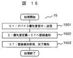
次に、管理端末140を用いた論理デバイス優先度定義処理の一実施例について図16用いて説明する。論理デバイス優先度定義処理15は、障害発生時にキャッシュメモリ112上のダーティデータをディスク装置114に反映する順序を定義するための処理である。まず、管理端末140のCPU145は、ストレージ管理者から入力装置141を用いて論理デバイスの優先度を受け付ける。入力パラメータには、論理デバイス番号と論理デバイス優先度を含む。管理端末140は、その後、入力パラメータをストレージ110に送信する(ステップ1501)。管理端末140より入力パラメータを受け取ったストレージ110は、入力パラメータに基づき、図3に示す論理デバイス管理テーブル2の論理デバイス番号と論理デバイス優先度を設定し、管理端末140に登録が完了したことを通知する(ステップ1502)。ストレージ110から登録完了報告を受けた管理端末140はストレージ管理者に完了報告を行う(ステップ1503)。従って、ストレージ110の制御装置130は、障害発生時に、上記論理デバイス優先度定義処理15によって設定された論理デバイスの優先度に基づいた順序で、キャッシュメモリ112上のダーティデータをディスク装置114に反映する処理を行うことが可能となる。 Next, an example of logical device priority definition processing using the
次に、管理端末140を用いたホスト優先度定義処理の一実施例について図17を用いて説明する。ホスト優先度定義処理16は、ホスト100からの入出力要求の処理優先度を定義する処理である。まず、管理端末140のCPU145は、ストレージ管理者から入力装置141により、ホスト100の優先度を受け付ける。入力パラメータには、ホスト番号と優先度を含む。管理端末140は、その後、入力パラメータをストレージ110に送信する(ステップ1601)。管理端末140より入力パラメータを受け取ったストレージ110は、入力パラメータに基づき、図10に示すホスト管理テーブル9のホスト優先度903を設定し、管理端末140に登録が完了したことを通知する(ステップ1602)。ストレージ110から登録完了報告を受けた管理端末140はストレージ管理者に完了報告を行う(ステップ1603)。 Next, an example of host priority definition processing using the
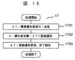
次に、管理端末140を用いた業務優先度定義処理の一実施例について図18を用いて説明する。まず、管理端末140のCPU145は、ストレージ管理者から入力装置141により、障害発生時に重要業務への性能低下を回避するための、業務の優先度(第二の優先度)を受け付ける。入力パラメータには、業務番号、論理デバイス番号とホスト番号の組、業務優先度を含む。管理端末140は、その後、入力パラメータをストレージ110に送信する(ステップ1701)。管理端末140より入力パラメータを受け取ったストレージ110は、入力パラメータに基づき、図12に示す業務管理テーブル11の論理デバイス番号1102、ホスト番号1103、業務優先度1104を設定し、管理端末140に登録が完了したことを通知する(ステップ1702)。ストレージ110から登録完了報告を受けた管理端末140はストレージ管理者に完了報告を行う(ステップ1703)。このように、ストレージ110は、管理端末140によって業務の優先度(第二の優先度)が設定されるので、障害発生時に設定された業務の優先度を用いてストレージ内のジョブをスケジューリングする処理を行うことが可能となり、その結果重要業務への性能低下を回避することが可能となる。なお、業務優先度は、ホスト優先度であってもよい。 Next, an example of business priority definition processing using the
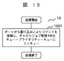
次に、チャネルアダプタ120におけるチャネルアダプタポート処理の一実施例について図19を用いて説明する。チャネルアダプタポート処理18では、チャネルアダプタ120は、ポート121を介してホスト100からのコマンドを受け付け、図8に示すチャネルジョブ管理テーブル7にジョブを登録する。本処理においては、ジョブを図示しないFIFOキュー、論理デバイスプライオリティーキュー、ホストプライオリティキュー、業務プライオリティーキューにエンキューする(ステップ1801)。プライオリティーキューは平衡木やB木などの公知のデータ構造により実現される。論理デバイスプライオリティーキュー、ホストプライオリティキュー、業務プライオリティーキューにエンキューする際の優先度の値としては、それぞれ、図3に示す論理デバイス管理テーブル2における、ホスト100からのリード・ライトコマンドに対応する論理デバイスの論理デバイス優先度207、図10に示すホスト管理テーブル9におけるホスト優先度903、図12に示す業務管理テーブル11における業務優先度1104を用いる。 Next, an example of channel adapter port processing in the
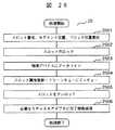
次に、本発明に係る制御装置であるチャネルアダプタ120におけるジョブスケジューリング処理の一実施例について図20を用いて説明する。チャネルアダプタ120におけるジョブスケジューリング処理19では、チャネルアダプタ120は、まず、障害が発生している状態であるかを判定し(ステップ1901)、障害が発生していなければ、図8に示すチャネルジョブ管理テーブル7のジョブが接続されている図示しないFIFOキューの端に位置するジョブをデキューし、当該ジョブを実行する(ステップ1902)。この際、当該ジョブは、図示しない論理デバイスプライオリティーキュー、ホストプライオリティキュー、業務プライオリティーキューからもデキューされる。チャネルアダプタ120は、障害が発生している場合には、図8に示すチャネルジョブ管理テーブル7のジョブが接続されている図示しない論理デバイスプライオリティーキュー、ホストプライオリティキュー、業務プライオリティーキューのいずれかのプライオリティーキューの最も優先度が高いジョブをデキューし、当該ジョブを実行する(ステップ1903)。プライオリティーキューの選択は、図13に示すスケジューリング管理テーブル12における論理デバイス優先度1201、ホスト優先度1202、業務優先度1203の比率(管理端末140が設定する。)を用いる。また、この際、当該ジョブは、図示しないFIFOキューからもデキューされる。ただし、プライオリティーキューのみによりジョブのスケジューリングを行うと、優先度の高いジョブのみが実行され、優先度の低いジョブが長期間実行されない可能性があるので、一定の割合で、プライオリティーキューのかわりにFIFOキューを用いる。以上説明したチャネルアダプタ120におけるジョブスケジューリング処理19の中で実行されるジョブは、図21に示すリードジョブ処理20もしくは図22に示すライトジョブ処理21を実行することになる。 Next, an example of job scheduling processing in the
次に、チャネルアダプタ120におけるリードジョブ処理の一実施例について図21を用いて説明する。チャネルアダプタ120におけるリードジョブ処理20では、キャッシュメモリ112上にホスト100からのリード要求対象データがあれば当該データをホスト100に転送し、なければディスクアダプタ130にリード要求対象データのステージングを要求する。まず、チャネルアダプタ120は、リード要求対象論理デバイスのデバイス状態をチェックし(ステップ2002)、「オンライン」以外であれば(エラー)、ホスト100にエラーを送信し、処理を終了する。チャネルアダプタ120は、エラーでなければ、ジョブスケジューリング処理19からの要求を解析し、リード要求対象データに対応するスロット番号、セグメント位置、ブロック位置を算出する(ステップ2002)。その後、スロット番号に対応するスロットの参照および更新を行うが、他のチャネルアダプタ120およびディスクアダプタ130が当該スロットに同時にアクセスしないように当該スロットのロックを取得する(ステップ2003)。具体的には、図6に示すスロット管理テーブル5のロック情報に「オン」を設定する。以後、ロックの取得の処理はここで説明した処理と同様であるので、説明を省略する。次に、リード要求対象データのヒットミス判定を行う(ステップ2004)。具体的には、スロット管理テーブル5より、対象となるスロット番号に対応するセグメント番号リストを参照し、対象となるセグメント位置のセグメント番号を得る。次に、セグメント管理テーブル6より、対象となるセグメント番号に対応するブロック情報を参照し、対象となるブロック位置のデータが有効か無効かを判定する。 Next, an example of read job processing in the
チャネルアダプタ120は、ステップ2004において当該データが有効な場合(ヒット)には、まず、アクセス情報を更新する(ステップ2005)。具体的には、リード要求対象データに対応する、アクセスパターン管理テーブル10における論理デバイスのリード回数とリードヒット回数を1だけインクリメントする。また、図示しない共有メモリ113上のシーケンシャル学習情報(連続する領域に対するリードアクセス情報)より、当該リード要求がシーケンシャルリードであるかを判定する。シーケンシャルリードとは、ホスト100から論理デバイスに対して論理デバイスのアドレス空間における連続した一連のリードアクセスである。シーケンシャルリードを検出した際、ホスト100からの要求とは非同期に当該論理デバイスに対する最後のリードアクセスのデータ以降のデータを先読みする。これにより、同期リード処理において、リード要求がヒットする確率が高くなり、高速なリードアクセスが期待できる。シーケンシャルリードであれば、リード要求対象データに対応する、アクセスパターン管理テーブル10における論理デバイスのシーケンシャルリード回数を1だけインクリメントする。その後、当該スロットをクリーンキューのMRUの端に遷移させる(ステップ2006)。次に、シーケンシャル学習情報に基づき、当該リード要求がシーケンシャルリードであれば、先読みのために、ディスクジョブ管理テーブル8に1または複数のジョブを登録する(ステップ2007)。具体的には、図19において説明した手順と同様にFIFOキュー、論理デバイスプライオリティーキュー、ホストプライオリティキュー、業務プライオリティーキューにジョブをエンキューする。最後に、ホスト100に対象となるデータを転送し(ステップ2008)、スロットのロックを開放する(ステップ2009)。具体的には、スロット管理テーブル5のロック情報に「オフ」を設定する。以後、ロックの解放の処理はここで説明した処理と同様であるので、説明を省略する。以上がヒットの場合の処理である。 If the data is valid (hit) in
チャネルアダプタ120は、ステップ2004において当該データが無効な場合(ミス)には、まず、アクセス情報を更新する(ステップ2010)。具体的には、リード要求対象データに対応する、アクセスパターン管理テーブル10における論理デバイスのリード回数を1だけインクリメントする。アクセスパターン管理テーブル10のシーケンシャルリード回数の更新はヒットの場合と同様に行う。次に、必要数のキャッシュセグメントの新規確保を行う(ステップ2011)。キャッシュセグメントの新規確保は、図示しない使用されていないキャッシュセグメントを管理するキュー(フリーキュー)に接続されているキャッシュセグメント、もしくは、LRUアルゴリズムのような公知な技術によりキュー管理されている、スロット属性が「クリーン」であるスロットが保持するキャッシュセグメントを用いて行う。次に、ディスクジョブ管理テーブル8にジョブを登録する(ステップ2012)。具体的には、図19において説明した手順と同様にFIFOキューとプライオリティーキューにジョブをエンキューする。次に、シーケンシャル学習情報に基づき、先読み処理を行うが、具体的な手順はヒット時で説明した手順と同様である(ステップ2013)。その後、スロットのロックを解放し(ステップ2014)、ディスクアダプタ130でステージングが完了するまで待つ(ステップ2015)。ディスクアダプタ130よりステージングの完了報告を受信(ステップ2016)したのち、再びステップ2003の処理から再開する。この後のヒットミス判定処理においては、すでにステージングが完了しているため、以後の処理はヒットの場合と同様になる。 If the data is invalid (miss) in
次に、チャネルアダプタ120におけるライトジョブ処理の一実施例について図22を用いて説明する。チャネルアダプタ120におけるライトジョブ処理21では、ホスト100からライト要求対象データを受信しキャッシュメモリ112に格納した後、必要であればディスクアダプタ130に対象データのデステージングを要求し、ホスト100に完了報告を行う。まず、チャネルアダプタ120は、ライト要求対象論理デバイスのデバイス状態をチェックし(ステップ2101)、「オンライン」以外であれば(エラー)、ホスト100にエラーを送信し、処理を終了する。チャネルアダプタ120は、エラーでなければ、ジョブスケジューリング処理19からの要求を解析し、ライト要求対象データに対応するスロット番号、セグメント位置、ブロック位置を算出する(ステップ2102)。その後、図21で説明した理由と同様の理由により、スロット番号に対応するスロットのロックを取得する(ステップ2103)。次に、図21で説明した手順と同様にライト要求対象データのヒットミス判定を行う(ステップ2104)。 Next, an example of write job processing in the
チャネルアダプタ120は、ヒットの場合には、まず、アクセス情報を更新する(ステップ2105)。具体的には、ライト要求対象データに対応する、アクセスパターン管理テーブル10における論理デバイスのライト回数とライトヒット回数を1だけインクリメントする。また、図示しない共有メモリ113上のシーケンシャル学習情報より、当該ライト要求がシーケンシャルライトであるかを判定する。シーケンシャルライトとは、ホスト100から論理デバイスに対して論理デバイスのアドレス空間における連続した一連のライトアクセスである。シーケンシャルライトであれば、ライト要求対象データに対応する、アクセスパターン管理テーブル10における論理デバイスのシーケンシャルライト回数を1だけインクリメントする。次に、ホスト100に転送準備完了のメッセージを送信する(ステップ2106)。その後、ホスト100からライト要求対象データを受信し、キャッシュメモリ112に格納して、ダーティキューのMRUの端にキュー遷移を行う(ステップ2107)。 In the case of a hit, the
チャネルアダプタ120は、ミスの場合には、まず、アクセス情報を更新する(ステップ2108)。具体的には、ライト要求対象データに対応する、アクセスパターン管理テーブル10における論理デバイスのライト回数を1だけインクリメントする。アクセスパターン管理テーブル10のシーケンシャルライト回数の更新はヒットの場合と同様に行う。次に、必要数のキャッシュセグメントを新規確保(ステップ2109)した後に、ホスト100に転送準備完了のメッセージを送信する(ステップ2110)。その後、ホスト100からライト要求対象データを受信し、キャッシュメモリ112に格納して、ダーティキューのMRUの端にエンキューする(ステップ2111)。 If there is a mistake, the
以後の処理は同期ライトが必要かどうかで処理が異なる(ステップ2112)。同期ライトが必要な場合とは、後述する共有メモリ113上の障害発生中フラグが「ON」のときであり、不要な場合とは、同フラグが「OFF」のときである。同期ライトが不要な場合は、ホスト100にライト完了報告を送信する(ステップ2117)。同期ライトが必要な場合は、ディスクジョブ管理テーブル8にジョブを登録する(ステップ2113)。具体的には、図19において説明した手順と同様にFIFOキューとプライオリティーキューにジョブをエンキューする。その後、スロットのロックを解放し(ステップ2114)、ディスクアダプタでデステージングが完了するまで待つ(ステップ2115)。ディスクアダプタ130よりデステージングの完了報告を受信(ステップ2116)した後、ホスト100に完了報告を送信する(ステップ2117)。同期ライト処理では、データがディスク装置114に確実に書き込まれることが保障される。 The subsequent processing differs depending on whether synchronous writing is necessary (step 2112). The case where the synchronous write is necessary is when a failure occurrence flag on the shared
以上がチャネルアダプタ120によるジョブスケジューリング処理19である。 The
次に、本発明に係る制御装置であるディスクアダプタ130におけるジョブスケジューリング処理の一実施例について図23を用いて説明する。ディスクアダプタ130におけるジョブスケジューリング処理22は、図20で説明した手順と異なりチャネルジョブ管理テーブル7ではなくディスクジョブ管理テーブル8を用いる点と以下で述べる障害発生時のダーティデータに関する処理が追加されている点を除いては、図20の説明と同様の手順で処理を行う。即ち、ディスクアダプタ130は、まず、障害が発生している状態であるかを判定し(ステップ2201)、障害が発生していなければ、図9に示すディスクジョブ管理テーブル8のジョブが接続されている図示しないFIFOキューの端に位置するジョブをデキューし、当該ジョブを実行する(ステップ2202)。ディスクアダプタ130は、障害が発生している場合には、図9に示すディスクジョブ管理テーブル8のジョブが接続されている図示しない論理デバイスプライオリティーキュー、ホストプライオリティキュー、業務プライオリティーキューのいずれかのプライオリティーキューの最も優先度が高いジョブをデキューし、当該ジョブを実行する(ステップ2203)。そして、ディスクアダプタ130は、ステップ2204では、障害発生時に、論理デバイス管理テーブル2の障害発生時データ退避情報209をチェックし、キャッシュメモリ112上のダーティデータがディスク装置114に完全に退避されていないことを示す「未完了」が設定されている論理デバイスに関して、アクセスパターン管理テーブル10のダーティ量管理情報1008のダーティデータ量の現在値を参照し、値がゼロであれば、障害発生時データ退避情報209に「完了」を設定する。以上説明したディスクアダプタ130におけるジョブスケジューリング処理22の中で実行されるジョブは、図25に示すリードジョブ処理24もしくは図26に示すライトジョブ処理25を実行することになる。 Next, an example of job scheduling processing in the
次に、ディスクアダプタ130における非同期ライトジョブ登録処理の一実施例について図24を用いて説明する。ディスクアダプタ130における非同期ライトジョブ登録処理23では、キャッシュメモリ112に格納されたライトデータを物理デバイスに書き込む。まず、ダーティキューのLRUの端より対象となるスロットを選択し、ダーティキューからデキューする(ステップ2301)。次に、ディスクジョブ管理テーブル8にジョブを登録する(ステップ2302)。具体的には、図19において説明した手順と同様にFIFOキューとプライオリティーキューにジョブをエンキューする。 Next, an embodiment of asynchronous write job registration processing in the
次に、ディスクアダプタ130におけるリードジョブ処理の一実施例について図25を用いて説明する。ディスクアダプタ130におけるリードジョブ処理24では、まず、ジョブスケジューリング処理22からの要求を解析し、リード要求対象データに対応するスロット番号、セグメント位置、ブロック位置を算出する(ステップ2401)。その後、スロット番号に対応するスロットの参照および更新を行うが、他のディスクアダプタ130およびチャネルアダプタ120が当該スロットに同時にアクセスしないように当該スロットのロックを取得する(ステップ2402)。次に、物理デバイスからリード要求対象データを読み出し、キャッシュメモリ112に格納し、クリーンキューのMRUの端にエンキュー(ステップ2403)した後、スロットのロックを解放し(ステップ240 4)、ディスクジョブ管理テーブル8のチャネルジョブ番号807で指定されたチャネルジョブに対応するチャネルアダプタ120に対してステージング完了報告を送信する(ステップ2405)。 Next, an example of read job processing in the
次に、ディスクアダプタ130におけるライトジョブ処理の一実施例について図26を用いて説明する。ディスクアダプタ130におけるライトジョブ処理25では、まず、ジョブスケジューリング処理22からの要求を解析し、ライト要求対象データに対応するスロット番号、セグメント位置、ブロック位置を算出する(ステップ2501)。次に、当該スロットのロックを取得し(ステップ2502)、当該スロットが保持するダーティデータを物理デバイスに書き込む(ステップ2503)。その後、当該スロットのスロット属性を「クリーン」に更新し、クリーンキューにエンキューする(ステップ2504)。最後に、当該スロットのロックを解放し(ステップ2505)、当該ライトジョブが同期ライトであればディスクジョブ管理テーブル8のチャネルジョブ番号807で指定されたチャネルジョブに対応するチャネルアダプタ120に対してデステージング完了報告を送信する(ステップ2506)。 Next, an example of write job processing in the
以上がディスクアダプタ130によるジョブスケジューリング処理22である。 The
次に、本発明に係る障害処理の一実施例について図27を用いて説明する。障害処理26では、障害発生検出時に、制御装置120、130が各論理デバイスに関するキャッシュメモリ112上のダーティデータを物理デバイスに反映するための処理である。まず、ディスクアダプタ130は障害処理を終了するかを判定する(ステップ2601)。具体的には、ストレージ110の動作を停止する場合などに処理を終了する。処理を終了しない場合、ディスクアダプタ130はストレージ110内の各部位に障害が発生しているかをチェックする(ステップ2602)。次に、ディスクアダプタ130は、障害が発生しているかを判定し(ステップ2603)、障害発生を検出した場合は、図3で説明したように障害発生時データ退避情報209を設定し、図示しない共有メモリ113上の障害発生中フラグを「ON」に設定する(ステップ2604)。ここで、障害発生中フラグは通常時、「OFF」に設定されている。その後、チャネルアダプタ120は、各論理デバイスのダーティデータに関するライトジョブのエンキュー処理を行う(ステップ2605)。具体的には、チャネルアダプタ120は、各論理デバイスに関してアクセスパターン管理テーブル10のダーティ量管理情報1008の現在値を参照し、値がゼロでない論理デバイスについて、当該論理デバイスの論理アドレス空間を走査し、スロット属性が「ダーティ」であるスロットを検索する。そして、当該スロットに対応するライトジョブをディスクジョブ管理テーブル8に登録する。具体的には、図19において説明した手順と同様にFIFOキューとプライオリティーキューにジョブをエンキューする。ディスクアダプタ130が、ステップ2603において、障害発生を検出しなかった場合は、ステップ2601に戻る。チャネルアダプタ120は、ステップ2605の後、対象ライトジョブの完了を待つ。ディスクアダプタ130がこの過程で予備電源不足もしくは対象キャッシュデータに関してキャッシュメモリの二重障害を検出(ステップ2606)した場合には、対象論理デバイスのデータは消失したことになるので、チャネルアダプタ120は対象論理デバイスのデバイス状態を「障害オフライン」に設定する(ステップ2607)。ステップ2606においてすべてのライトが完了した場合にはステップ2601に戻る。 Next, an example of failure processing according to the present invention will be described with reference to FIG. The
本発明に係る別の実施の形態としては、ストレージ110に障害発生後、図27に示す障害処理26によるライトデータの反映が終了しなかった場合もしくはキャッシュに二重傷害が発生した場合に、キャッシュメモリ112上のダーティデータが消失した際、当該データのスロット位置を管理端末140のディスプレイ142に表示するものである。本実施形態においては、論理デバイス管理テーブル2を参照し、障害時データ退避情報が「未完了」である論理デバイスに対応するダーティデータのスロット位置をスロット管理テーブル5を参照することにより算出し、該当するスロット番号をすべて論理デバイス番号と共にディスプレイ142に表示する。これにより、ストレージ管理者は消失したデータ領域にもをリカバリすることで、リカバリ時間の短縮が可能となる。 As another embodiment according to the present invention, when a failure occurs in the
以上説明したように本実施の形態によれば、ストレージに障害が発生した際に、ストレージ内のキャッシュメモリ上のダーティデータを速やかにディスク装置に反映することができ、優先度の高い重要なデータの消失を回避することができる。また、ストレージに障害が発生した際に、優先度の高い重要な業務に関する性能低下を極力回避することができる。 As described above, according to the present embodiment, when a failure occurs in the storage, the dirty data in the cache memory in the storage can be quickly reflected in the disk device, and important data with a high priority. Disappearance can be avoided. In addition, when a failure occurs in the storage, it is possible to avoid performance degradation related to important business with high priority as much as possible.
100…ホスト、110…ストレージ、111…相互結合網、112…キャッシュメモリ、113…共有メモリ、114…ディスク装置、115…接続線、116…電源、117…予備電源、118…電力線、120…チャネルアダプタ、121…ポート、130…ディスクアダプタ、140…管理端末、141…入力装置、142…ディスプレイ、143…メモリ、144…記憶装置、145…CPU、146…I/F、
2…論理デバイス管理テーブル、3…LUパス管理テーブル、4…物理デバイス管理テーブル、5…スロット管理テーブル、6…セグメント管理テーブル、7…チャネルジョブ管理テーブル、8…ディスクジョブ管理テーブル、9…ホスト管理テーブル、10…アクセスパターン管理テーブル、11…業務管理テーブル、12…スケジューリング管テーブル、13…論理デバイス定義処理、14…LUパス定義処理、15…論理デバイス優先度定義処理、18…チャネルアダプタポート処理(チャネルアダプタ)、19…ジョブスケジューリング処理(チャネルアダプタ)、20…リードジョブの処理(チャネルアダプタ)、21…ライトジョブの処理(チャネルアダプタ)、22…ジョブスケジューリング処理(ディスクアダプタ)、24…リードジョブの処理(ディスクアダプタ)、25…ライトジョブの処理(ディスクアダプタ)、16…ホスト優先度定義処理、17…業務優先度定義処理。DESCRIPTION OF
2 ... Logical device management table, 3 ... LU path management table, 4 ... Physical device management table, 5 ... Slot management table, 6 ... Segment management table, 7 ... Channel job management table, 8 ... Disk job management table, 9 ... Host Management table, 10 ... Access pattern management table, 11 ... Business management table, 12 ... Scheduling management table, 13 ... Logical device definition processing, 14 ... LU path definition processing, 15 ... Logical device priority definition processing, 18 ... Channel adapter port Processing (channel adapter), 19 ... job scheduling processing (channel adapter), 20 ... read job processing (channel adapter), 21 ... write job processing (channel adapter), 22 ... job scheduling processing (disk adapter), 24 Processing the read job (disk adapter), 25 ... processing of write job (disk adapter), 16 ... host priority definition processing, 17 ... operational priority definition processing.
Claims (24)
Translated fromJapanese前記ホストに提供する論理デバイスに対する第一の優先度情報を受け付ける管理端末を接続し、
前記制御装置は、前記管理端末から受け付けた第一の優先度情報に従って、優先度の高い論理デバイスは優先度の低い論理デバイスよりも多くの物理デバイスを割り当てておき、障害発生時には前記キャッシュメモリ内に格納されている論理デバイスのデータをこの論理デバイスに対応付けられている複数の物理デバイスに格納するように制御することを特徴とするストレージ装置。A storage device comprising a port that is an interface with a host, a cache memory, a control device connected to the port, the cache memory, and the shared memory by connection lines, and a disk device connected to the control device. And
Connect a management terminal that receives first priority information for a logical device provided to the host,
In accordance with the first priority information received from the management terminal, the control device allocates more physical devices to logical devices with higher priorities than logical devices with lower priorities, and in the cache memory when a failure occurs A storage apparatus that controls to store data of a logical device stored in a plurality of physical devices associated with the logical device.
前記制御装置は、障害発生時には前記管理端末から受け付けた第二の優先度情報に従って、ストレージ内のプライオリティーキューの優先度が高いジョブをデキューし、該ジョブを実行するように制御することを特徴とする請求項1または2記載のストレージ装置。Further, the management terminal is configured to receive second priority information indicating a priority of work,
The control device controls to dequeue a job having a high priority in the priority queue in the storage and execute the job according to the second priority information received from the management terminal when a failure occurs. The storage apparatus according to claim 1 or 2.
業務の優先度を示す第二の優先度情報を受け付ける管理端末を接続し、
前記制御装置は、障害発生時には前記管理端末で受け付けた第二の優先度情報に従って、ストレージ内のプライオリティーキューの優先度が高いジョブをデキューし、該ジョブを実行するように制御することを特徴とするストレージ装置。A storage device comprising a port that is an interface with a host, a cache memory, a control device connected to the port, the cache memory, and the shared memory by connection lines, and a disk device connected to the control device. And
Connect a management terminal that accepts second priority information indicating the priority of the work,
The control device controls to dequeue a job having a high priority in the priority queue in the storage and execute the job in accordance with the second priority information received by the management terminal when a failure occurs. Storage device.
前記ホストに提供する論理デバイスに対する第一の優先度情報を受け付ける第1のステップと、
該第1のステップにおいて受け付けた第一の優先度情報に従って、優先度の高い論理デバイスは優先度の低い論理デバイスよりも多くの物理デバイスを割り当てておき、障害発生時には前記キャッシュメモリ内に格納されている論理デバイスのデータをこの論理デバイスに対応付けられている複数の物理デバイスに格納する第2のステップとを有することを特徴とするストレージ装置における制御方法。Control in a storage device comprising a port that is an interface with a host, a cache memory, a control device connected to the port, the cache memory, and the shared memory by a connection line, and a disk device connected to the control device A method,
A first step of receiving first priority information for a logical device provided to the host;
In accordance with the first priority information received in the first step, a logical device with a higher priority is assigned more physical devices than a logical device with a lower priority, and is stored in the cache memory when a failure occurs. And a second step of storing data of a logical device in a plurality of physical devices associated with the logical device.
障害発生時には前記第4のステップから受け付けた第二の優先度情報に従って、ストレージ内のプライオリティーキューの優先度が高いジョブをデキューし、該ジョブを実行するように制御する第5のステップとを有することを特徴とする請求項10または11記載のストレージ装置における制御方法。A fourth step of receiving second priority information indicating the priority of the job;
A fifth step of controlling to dequeue a job having a high priority in the priority queue in the storage and execute the job in accordance with the second priority information received from the fourth step when a failure occurs; 12. A control method in a storage apparatus according to claim 10 or 11, characterized by comprising:
前記ホストに提供する論理デバイスに対する第一の優先度情報を受け付ける第1のステップと、
該第1のステップにおいて受け付けた第一の優先度情報に従って、優先度の高い論理デバイスは優先度の低い論理デバイスよりも多くの物理デバイスを割り当てておき、障害発生時には前記キャッシュメモリ内に格納されている論理デバイスのデータをこの論理デバイスに対応付けられている複数の物理デバイスに格納する第2のステップとを有することを特徴とするストレージ装置における制御プログラム。Control in a storage device comprising a port that is an interface with a host, a cache memory, a control device connected to the port, the cache memory, and the shared memory by a connection line, and a disk device connected to the control device A program,
A first step of receiving first priority information for a logical device provided to the host;
In accordance with the first priority information received in the first step, a logical device with a higher priority is assigned more physical devices than a logical device with a lower priority, and is stored in the cache memory when a failure occurs. And a second step of storing data of a logical device in a plurality of physical devices associated with the logical device.
障害発生時には前記第4のステップから受け付けた第二の優先度情報に従って、ストレージ内のプライオリティーキューの優先度が高いジョブをデキューし、該ジョブを実行するように制御する第5のステップとを有することを特徴とする請求項14または15記載のストレージ装置における制御プログラム。A fourth step of receiving second priority information indicating the priority of the job;
A fifth step of controlling to dequeue a job having a high priority in the priority queue in the storage and to execute the job according to the second priority information received from the fourth step when a failure occurs; 16. The control program for a storage apparatus according to claim 14, further comprising:
障害が発生している状態であるかを判定する第7のステップと、
該第7のステップで障害が発生していると判定された場合には、ジョブ管理テーブルに登録されているジョブが接続されている論理デバイスプライオリティーキュー、ホストプライオリティーキュー、業務プライオリティーキューの何れかのプライオリティーキューの優先度の高いジョブをデキューし、該デキューしたジョブを実行する第8のステップとを有することを特徴とするストレージ装置におけるジョブスケジューリング処理方法。A job in a storage device comprising a port that is an interface with a host, a cache memory, a control device that is connected to the port, the cache memory, and the shared memory by a connection line, and a disk device that is connected to the control device A scheduling processing method comprising:
A seventh step of determining whether a failure has occurred;
If it is determined in the seventh step that a failure has occurred, the logical device priority queue, host priority queue, business priority queue to which the job registered in the job management table is connected are stored. A job scheduling processing method in a storage apparatus, comprising: an eighth step of dequeuing a job having a high priority in any priority queue and executing the dequeued job.
障害が発生している状態であるかを判定する第7のステップと、
該第7のステップで障害が発生していると判定された場合には、ジョブ管理テーブルに登録されているジョブが接続されている論理デバイスプライオリティーキュー、ホストプライオリティーキュー、業務プライオリティーキューの何れかのプライオリティーキューの優先度の高いジョブをデキューし、該デキューしたジョブを実行する第8のステップとを有することを特徴とするストレージ装置におけるジョブスケジューリング処理プログラム。A job in a storage device comprising a port that is an interface with a host, a cache memory, a control device that is connected to the port, the cache memory, and the shared memory by a connection line, and a disk device that is connected to the control device A scheduling processing program comprising:
A seventh step of determining whether a failure has occurred;
If it is determined in the seventh step that a failure has occurred, the logical device priority queue, host priority queue, business priority queue to which the job registered in the job management table is connected are stored. A job scheduling processing program in a storage apparatus, comprising: an eighth step of dequeuing a job having a high priority in any priority queue and executing the dequeued job.
障害処理を終了するか否かを判定する第10のステップと、
該第10のステップで処理を終了しない場合、ステレージ装置内の各部位に障害が発生しているかをチェックする第11のステップと、
該第11のステップのチェック結果で障害が検出された場合には、キャッシュメモリ上にダーティデータを有する論理デバイスに関する障害発生時データ退避情報を設定する第12のステップと、
その後、各論理デバイスに関するキャッシュメモリ上のダーティデータを物理デバイスに反映させるために各論理デバイスのダーティデータに関するライトジョブのエンキュー処理を行う第13のステップと、
その後、対象ライトジョブの完了を待ち、この過程で予備電源不足若しくはキャッシュメモリの二重障害が検出されたときに、対象論理デバイスのデバイス状態を障害オフラインに設定する第14のステップとを有することを特徴とするストレージ装置における障害処理方法。Failure in a storage device comprising a port that is an interface with a host, a cache memory, a control device connected to the port, the cache memory, and the shared memory by a connection line, and a disk device connected to the control device A processing method,
A tenth step for determining whether or not to terminate the fault processing;
An eleventh step of checking whether a failure has occurred in each part in the storage device if the process is not terminated in the tenth step;
If a failure is detected in the check result of the eleventh step, a twelfth step of setting failure occurrence data saving information related to a logical device having dirty data on the cache memory;
Thereafter, a thirteenth step of enqueuing a write job relating to the dirty data of each logical device in order to reflect the dirty data in the cache memory relating to each logical device to the physical device;
Thereafter, the process waits for completion of the target write job, and has a fourteenth step of setting the device state of the target logical device to failure offline when a standby power shortage or a double failure of the cache memory is detected in this process. A failure processing method in a storage apparatus characterized by
障害処理を終了するか否かを判定する第10のステップと、
該第10のステップで処理を終了しない場合、ステレージ装置内の各部位に障害が発生しているかをチェックする第11のステップと、
該第11のステップのチェック結果で障害が検出された場合には、キャッシュメモリ上にダーティデータを有する論理デバイスに関する障害発生時データ退避情報を設定する第12のステップと、
その後、各論理デバイスに関するキャッシュメモリ上のダーティデータを物理デバイスに反映させるために各論理デバイスのダーティデータに関するライトジョブのエンキュー処理を行う第13のステップと、
その後、対象ライトジョブの完了を待ち、この過程で予備電源不足若しくはキャッシュメモリの二重障害が検出されたときに、対象論理デバイスのデバイス状態を障害オフラインに設定する第14のステップとを有することを特徴とするストレージ装置における障害処理プログラム。Failure in a storage device comprising a port that is an interface with a host, a cache memory, a control device connected to the port, the cache memory, and the shared memory by a connection line, and a disk device connected to the control device A processing program,
A tenth step for determining whether or not to terminate the fault processing;
An eleventh step of checking whether a failure has occurred in each part in the storage device if the process is not terminated in the tenth step;
If a failure is detected in the check result of the eleventh step, a twelfth step of setting failure occurrence data saving information related to a logical device having dirty data on the cache memory;
Thereafter, a thirteenth step of enqueuing a write job relating to the dirty data of each logical device in order to reflect the dirty data in the cache memory relating to each logical device to the physical device;
Thereafter, the process waits for completion of the target write job, and has a fourteenth step of setting the device state of the target logical device to failure offline when a standby power shortage or a double failure of the cache memory is detected in this process. A failure processing program in a storage apparatus characterized by
Priority Applications (2)
| Application Number | Priority Date | Filing Date | Title |
|---|---|---|---|
| JP2003390239AJP2005149436A (en) | 2003-11-20 | 2003-11-20 | Storage device, control method in storage device, job scheduling processing method, failure processing method, and program thereof |
| US10/771,453US7100074B2 (en) | 2003-11-20 | 2004-02-05 | Storage system, and control method, job scheduling processing method, and failure handling method therefor, and program for each method |
Applications Claiming Priority (1)
| Application Number | Priority Date | Filing Date | Title |
|---|---|---|---|
| JP2003390239AJP2005149436A (en) | 2003-11-20 | 2003-11-20 | Storage device, control method in storage device, job scheduling processing method, failure processing method, and program thereof |
Publications (1)
| Publication Number | Publication Date |
|---|---|
| JP2005149436Atrue JP2005149436A (en) | 2005-06-09 |
Family
ID=34649766
Family Applications (1)
| Application Number | Title | Priority Date | Filing Date |
|---|---|---|---|
| JP2003390239APendingJP2005149436A (en) | 2003-11-20 | 2003-11-20 | Storage device, control method in storage device, job scheduling processing method, failure processing method, and program thereof |
Country Status (2)
| Country | Link |
|---|---|
| US (1) | US7100074B2 (en) |
| JP (1) | JP2005149436A (en) |
Cited By (5)
| Publication number | Priority date | Publication date | Assignee | Title |
|---|---|---|---|---|
| JP2010506275A (en)* | 2006-10-02 | 2010-02-25 | ソニー デーアーデーツェー オーストリア アクチェンゲゼルシャフト | Method, control logic and system for detecting virtual storage volume and data carrier |
| US8234415B2 (en) | 2008-07-14 | 2012-07-31 | Fujitsu Limited | Storage device and control unit |
| JP5104855B2 (en)* | 2007-03-23 | 2012-12-19 | 富士通株式会社 | Load distribution program, load distribution method, and storage management apparatus |
| US8453009B2 (en) | 2009-10-16 | 2013-05-28 | Fujitsu Limited | Storage apparatus and control method for storage apparatus |
| JP2013532862A (en)* | 2010-12-27 | 2013-08-19 | 株式会社日立製作所 | Storage system and control method thereof |
Families Citing this family (25)
| Publication number | Priority date | Publication date | Assignee | Title |
|---|---|---|---|---|
| JP2000135820A (en)* | 1997-12-11 | 2000-05-16 | Canon Inc | PRINTING APPARATUS, PRINTING SYSTEM, PRINTING CONTROL METHOD, STORAGE MEDIUM CONTAINING PRINTING CONTROL PROGRAM FOR CONTROLLING PRINTING APPARATUS, AND SENDING APPARATUS FOR TRANSMITTING PRINTING CONTROL PROGRAM CONTROLLING PRINTING APPARATUS |
| US7269645B2 (en)* | 2003-10-31 | 2007-09-11 | International Business Machines Corporation | Seamless migration of one or more business processes and their work environment between computing devices and a network |
| EP1555772A3 (en)* | 2004-01-15 | 2013-07-17 | Yamaha Corporation | Remote control method of external devices |
| JP4141391B2 (en) | 2004-02-05 | 2008-08-27 | 株式会社日立製作所 | Storage subsystem |
| JP2005301442A (en)* | 2004-04-07 | 2005-10-27 | Hitachi Ltd | Storage device |
| US7260703B1 (en)* | 2004-08-20 | 2007-08-21 | Sun Microsystems, Inc. | Method and apparatus for I/O scheduling |
| US7386692B1 (en)* | 2004-08-20 | 2008-06-10 | Sun Microsystems, Inc. | Method and apparatus for quantized deadline I/O scheduling |
| JP4441929B2 (en)* | 2005-01-19 | 2010-03-31 | 日本電気株式会社 | Disk device and hot swap method |
| US7305537B1 (en) | 2005-03-01 | 2007-12-04 | Sun Microsystems, Inc. | Method and system for I/O scheduler activations |
| US20060294412A1 (en)* | 2005-06-27 | 2006-12-28 | Dell Products L.P. | System and method for prioritizing disk access for shared-disk applications |
| JP4831599B2 (en)* | 2005-06-28 | 2011-12-07 | ルネサスエレクトロニクス株式会社 | Processing equipment |
| US7253606B2 (en)* | 2005-07-18 | 2007-08-07 | Agilent Technologies, Inc. | Framework that maximizes the usage of testhead resources in in-circuit test system |
| US7478179B2 (en)* | 2005-11-04 | 2009-01-13 | Sun Microsystems, Inc. | Input/output priority inheritance wherein first I/O request is executed based on higher priority |
| US7657671B2 (en)* | 2005-11-04 | 2010-02-02 | Sun Microsystems, Inc. | Adaptive resilvering I/O scheduling |
| US20070106849A1 (en)* | 2005-11-04 | 2007-05-10 | Sun Microsystems, Inc. | Method and system for adaptive intelligent prefetch |
| US8055865B2 (en)* | 2007-08-06 | 2011-11-08 | International Business Machines Corporation | Managing write requests to data sets in a primary volume subject to being copied to a secondary volume |
| US8032689B2 (en)* | 2007-12-18 | 2011-10-04 | Hitachi Global Storage Technologies Netherlands, B.V. | Techniques for data storage device virtualization |
| US7975169B2 (en)* | 2008-06-03 | 2011-07-05 | International Business Machines Corporation | Memory preserved cache to prevent data loss |
| JP5729746B2 (en)* | 2009-09-17 | 2015-06-03 | 日本電気株式会社 | Storage system and disk array device |
| JP5402693B2 (en)* | 2010-02-05 | 2014-01-29 | 富士通株式会社 | Disk array device control method and disk array device |
| US9152490B2 (en)* | 2013-04-02 | 2015-10-06 | Western Digital Technologies, Inc. | Detection of user behavior using time series modeling |
| US9934083B2 (en) | 2015-10-14 | 2018-04-03 | International Business Machines Corporation | Requesting manual intervention on failure of initial microcode load attempts during recovery of modified customer data |
| US10261837B2 (en) | 2017-06-30 | 2019-04-16 | Sas Institute Inc. | Two-part job scheduling with capacity constraints and preferences |
| US10310896B1 (en) | 2018-03-15 | 2019-06-04 | Sas Institute Inc. | Techniques for job flow processing |
| CN114430362B (en)* | 2021-12-28 | 2024-04-12 | 东莞市李群自动化技术有限公司 | Link switching method, FPGA chip, equipment and storage medium |
Citations (4)
| Publication number | Priority date | Publication date | Assignee | Title |
|---|---|---|---|---|
| JPH044422A (en)* | 1990-04-23 | 1992-01-08 | Hitachi Ltd | Disk control device with cache and its data control method |
| JPH11288387A (en)* | 1998-12-11 | 1999-10-19 | Fujitsu Ltd | Disk cache device |
| JP2000089998A (en)* | 1998-09-09 | 2000-03-31 | Fujitsu Ltd | Remote file control device |
| JP2003308174A (en)* | 2002-04-16 | 2003-10-31 | Mitsubishi Electric Corp | Device-to-device data transfer device, device-to-device data transfer method, and program |
Family Cites Families (21)
| Publication number | Priority date | Publication date | Assignee | Title |
|---|---|---|---|---|
| US5148432A (en)* | 1988-11-14 | 1992-09-15 | Array Technology Corporation | Arrayed disk drive system and method |
| US5166939A (en)* | 1990-03-02 | 1992-11-24 | Micro Technology, Inc. | Data storage apparatus and method |
| US5341493A (en)* | 1990-09-21 | 1994-08-23 | Emc Corporation | Disk storage system with write preservation during power failure |
| JP3160106B2 (en)* | 1991-12-23 | 2001-04-23 | ヒュンダイ エレクトロニクス アメリカ | How to sort disk arrays |
| US5448719A (en) | 1992-06-05 | 1995-09-05 | Compaq Computer Corp. | Method and apparatus for maintaining and retrieving live data in a posted write cache in case of power failure |
| JP3264465B2 (en) | 1993-06-30 | 2002-03-11 | 株式会社日立製作所 | Storage system |
| US5657468A (en)* | 1995-08-17 | 1997-08-12 | Ambex Technologies, Inc. | Method and apparatus for improving performance in a reduntant array of independent disks |
| US5854942A (en)* | 1996-09-06 | 1998-12-29 | International Business Machines Corporation | Method and system for automatic storage subsystem configuration |
| US6061761A (en)* | 1997-10-06 | 2000-05-09 | Emc Corporation | Method for exchanging logical volumes in a disk array storage device in response to statistical analyses and preliminary testing |
| US6571354B1 (en)* | 1999-12-15 | 2003-05-27 | Dell Products, L.P. | Method and apparatus for storage unit replacement according to array priority |
| JP3845239B2 (en) | 1999-12-21 | 2006-11-15 | 日本電気株式会社 | Disk array device and failure recovery method in disk array device |
| JP4115060B2 (en) | 2000-02-02 | 2008-07-09 | 株式会社日立製作所 | Data recovery method for information processing system and disk subsystem |
| US6618798B1 (en)* | 2000-07-11 | 2003-09-09 | International Business Machines Corporation | Method, system, program, and data structures for mapping logical units to a storage space comprises of at least one array of storage units |
| WO2002065275A1 (en)* | 2001-01-11 | 2002-08-22 | Yottayotta, Inc. | Storage virtualization system and methods |
| US6687787B1 (en)* | 2001-03-05 | 2004-02-03 | Emc Corporation | Configuration of a data storage system |
| US6834315B2 (en) | 2001-03-26 | 2004-12-21 | International Business Machines Corporation | Method, system, and program for prioritizing input/output (I/O) requests submitted to a device driver |
| JP3997061B2 (en) | 2001-05-11 | 2007-10-24 | 株式会社日立製作所 | Storage subsystem and storage subsystem control method |
| US6567892B1 (en)* | 2001-05-23 | 2003-05-20 | 3Ware, Inc. | Use of activity bins to increase the performance of disk arrays |
| JP2003006016A (en) | 2001-06-26 | 2003-01-10 | Hitachi Ltd | Disk subsystem and asynchronous copy method between disk subsystems |
| JP2003330762A (en) | 2002-05-09 | 2003-11-21 | Hitachi Ltd | Storage system control method, storage system, switch, and program |
| US20040078508A1 (en)* | 2002-10-02 | 2004-04-22 | Rivard William G. | System and method for high performance data storage and retrieval |
- 2003
- 2003-11-20JPJP2003390239Apatent/JP2005149436A/enactivePending
- 2004
- 2004-02-05USUS10/771,453patent/US7100074B2/ennot_activeExpired - Fee Related
Patent Citations (4)
| Publication number | Priority date | Publication date | Assignee | Title |
|---|---|---|---|---|
| JPH044422A (en)* | 1990-04-23 | 1992-01-08 | Hitachi Ltd | Disk control device with cache and its data control method |
| JP2000089998A (en)* | 1998-09-09 | 2000-03-31 | Fujitsu Ltd | Remote file control device |
| JPH11288387A (en)* | 1998-12-11 | 1999-10-19 | Fujitsu Ltd | Disk cache device |
| JP2003308174A (en)* | 2002-04-16 | 2003-10-31 | Mitsubishi Electric Corp | Device-to-device data transfer device, device-to-device data transfer method, and program |
Cited By (7)
| Publication number | Priority date | Publication date | Assignee | Title |
|---|---|---|---|---|
| JP2010506275A (en)* | 2006-10-02 | 2010-02-25 | ソニー デーアーデーツェー オーストリア アクチェンゲゼルシャフト | Method, control logic and system for detecting virtual storage volume and data carrier |
| US8429345B2 (en) | 2006-10-02 | 2013-04-23 | Sony Dadc Austria Ag | Method, control logic and system for detecting a virtual storage volume and data carrier |
| JP5104855B2 (en)* | 2007-03-23 | 2012-12-19 | 富士通株式会社 | Load distribution program, load distribution method, and storage management apparatus |
| US8516070B2 (en) | 2007-03-23 | 2013-08-20 | Fujitsu Limited | Computer program and method for balancing processing load in storage system, and apparatus for managing storage devices |
| US8234415B2 (en) | 2008-07-14 | 2012-07-31 | Fujitsu Limited | Storage device and control unit |
| US8453009B2 (en) | 2009-10-16 | 2013-05-28 | Fujitsu Limited | Storage apparatus and control method for storage apparatus |
| JP2013532862A (en)* | 2010-12-27 | 2013-08-19 | 株式会社日立製作所 | Storage system and control method thereof |
Also Published As
| Publication number | Publication date |
|---|---|
| US20050132256A1 (en) | 2005-06-16 |
| US7100074B2 (en) | 2006-08-29 |
Similar Documents
| Publication | Publication Date | Title |
|---|---|---|
| JP2005149436A (en) | Storage device, control method in storage device, job scheduling processing method, failure processing method, and program thereof | |
| JP7135162B2 (en) | Information processing system, storage system and data transfer method | |
| US8347060B2 (en) | Storage system, storage extent release method and storage apparatus | |
| EP2026188B1 (en) | Storage system | |
| US8402220B2 (en) | Storage controller coupled to storage apparatus | |
| US7171522B2 (en) | Storage system including storage adaptors having cache memories and grasping usage situation of each cache memory and equalizing usage of cache memories | |
| US8402234B2 (en) | Storage system and storage migration method | |
| US20070162692A1 (en) | Power controlled disk array system using log storage area | |
| US20150081971A1 (en) | Storage system and storage control method | |
| EP1785829A1 (en) | Virtual volume control method involving device stop | |
| US20060077724A1 (en) | Disk array system | |
| WO2002003204A1 (en) | Three interconnected raid disk controller data processing system architecture | |
| US20110246720A1 (en) | Storage system with multiple controllers | |
| US10503440B2 (en) | Computer system, and data migration method in computer system | |
| US8954666B2 (en) | Storage subsystem | |
| JP7318367B2 (en) | Storage control device and storage control program | |
| US8275958B2 (en) | Storage system with remote copy controllers | |
| US8762671B2 (en) | Storage apparatus and its control method | |
| US7451284B2 (en) | Storage system and control method of the same | |
| JP5597266B2 (en) | Storage system | |
| US20050223180A1 (en) | Accelerating the execution of I/O operations in a storage system | |
| WO2016006108A1 (en) | Storage and control method therefor | |
| JP2000311112A (en) | Information system |
Legal Events
| Date | Code | Title | Description |
|---|---|---|---|
| A621 | Written request for application examination | Free format text:JAPANESE INTERMEDIATE CODE: A621 Effective date:20060111 | |
| RD02 | Notification of acceptance of power of attorney | Free format text:JAPANESE INTERMEDIATE CODE: A7422 Effective date:20060111 | |
| A977 | Report on retrieval | Free format text:JAPANESE INTERMEDIATE CODE: A971007 Effective date:20081218 | |
| A131 | Notification of reasons for refusal | Free format text:JAPANESE INTERMEDIATE CODE: A131 Effective date:20090106 | |
| A521 | Written amendment | Free format text:JAPANESE INTERMEDIATE CODE: A523 Effective date:20090304 | |
| A131 | Notification of reasons for refusal | Free format text:JAPANESE INTERMEDIATE CODE: A131 Effective date:20090825 | |
| A02 | Decision of refusal | Free format text:JAPANESE INTERMEDIATE CODE: A02 Effective date:20100209 |