Movatterモバイル変換


[0]ホーム

URL:


JP2005145523A - Packaging container and packaging method - Google Patents

Packaging container and packaging method
Download PDF

Info

Publication number
JP2005145523A
JP2005145523AJP2003387364AJP2003387364AJP2005145523AJP 2005145523 AJP2005145523 AJP 2005145523AJP 2003387364 AJP2003387364 AJP 2003387364AJP 2003387364 AJP2003387364 AJP 2003387364AJP 2005145523 AJP2005145523 AJP 2005145523A
Authority
JP
Japan
Prior art keywords
cover
side plate
plate
packaging
outer box
Prior art date
Legal status (The legal status is an assumption and is not a legal conclusion. Google has not performed a legal analysis and makes no representation as to the accuracy of the status listed.)
Pending
Application number
JP2003387364A
Other languages
Japanese (ja)
Inventor
Hiromu Iwakawa
煕 岩川
Yuri Morikawa
由理 森川
Kenichi Takahashi
健一 高橋
Current Assignee (The listed assignees may be inaccurate. Google has not performed a legal analysis and makes no representation or warranty as to the accuracy of the list.)
National Federation of Agricultural Cooperative Associations
Chuetsu Tec Co Ltd
Original Assignee
National Federation of Agricultural Cooperative Associations
Chuetsu Tec Co Ltd
Priority date (The priority date is an assumption and is not a legal conclusion. Google has not performed a legal analysis and makes no representation as to the accuracy of the date listed.)
Filing date
Publication date
Application filed by National Federation of Agricultural Cooperative Associations, Chuetsu Tec Co LtdfiledCriticalNational Federation of Agricultural Cooperative Associations
Priority to JP2003387364ApriorityCriticalpatent/JP2005145523A/en
Publication of JP2005145523ApublicationCriticalpatent/JP2005145523A/en
Pendinglegal-statusCriticalCurrent

Links

Images

Landscapes

Abstract

<P>PROBLEM TO BE SOLVED: To provide a packaging container which can be assembled easily, facilitates loading and unloading of an article such as grape or cherry, and is safe to be free from a concern of the collapse of the bottom of the container. <P>SOLUTION: The container comprises a transparent see-through cover 11, which is formed into a box shape with an open under face and has a tabular cover top face 14, a cover front side board 19, a cover rear side board 20, and cover left/right side boards 21, 22, all the cover side boards formed to be integral to the cover top face 14 via folds. The container also includes a packaging outer box 13, into which the see-through cover 11 is fitted with the open under face directed downward and which has a tabular outer box bottom board 38, a outer box front board 43, an outer box rear side board 44, and outer box left/right side boards 45, 46, all the side boards erected on the periphery of the bottom board 38. The article A is put in the container so that the article A can be seen through the see-through cover 11. <P>COPYRIGHT: (C)2005,JPO&NCIPI

Description

Translated fromJapanese

本発明は、主に巨峰等の果物を包装するための包装用容器及び包装方法に関する。  The present invention mainly relates to a packaging container and packaging method for packaging fruits such as Kyoho.

従来、巨峰等の果物の包装には、店頭における展示を考慮し、上面が開口し、その開口部に透明なプラスチック製カバー1を被せ、粘着テープ1aで固定した包装用箱2を使用し、透明なプラスチック製カバー1を通して巨峰等の収容物を外部より見ることができるようにしている。  Conventionally, for packaging fruit such as Kyoho, using apackaging box 2 that is open at the top, covered with a transparentplastic cover 1 and fixed with adhesive tape 1a in consideration of display at the storefront, Through the transparentplastic cover 1, the contents such as Kyoho can be seen from the outside.

このような巨峰等の収容物の包装に用いられる包装用箱2は、例えば、図29に示すように、底面を構成するフラップ板3,3と、このフラップ板3と重なり合う開閉自在なフラップ式の蓋4を備え、見栄えを良くするために収容物を上面部より挿入せずに、そのフラップ板3,3及び蓋4を開き、箱の底部より巨峰等の収容物を出し入れするようになっている。  For example, as shown in FIG. 29, thepackaging box 2 used for packaging such a container such as Kyoho hasflap plates 3 and 3 constituting a bottom surface, and an openable / closable flap type overlapping theflap plate 3. In order to improve the appearance, theflap plates 3 and 3 and the lid 4 are opened without inserting the contents from the upper surface, and the contents such as the kyoho are taken in and out from the bottom of the box. ing.

また、この包装用箱2は、箱の上面を覆う天板6と、その両側縁に折り目を介して一体に形成された側板7,7とからなる外カバー5を備え、運搬する際等にはその外面を外カバー5により覆うようになっている。  Thepackaging box 2 includes anouter cover 5 including a top plate 6 that covers the upper surface of the box andside plates 7 and 7 that are integrally formed on both side edges via folds. The outer surface is covered with anouter cover 5.

この外カバー5は、側板7,7の天板6とは反対側の縁部に係止片8,8を一体に備え、その係止片8,8をそれぞれ包装用箱2の周壁の下端に形成された挿入孔9及び蓋4の縁部に形成された挿入孔9にそれぞれ挿入することによって、外カバー5によって蓋4を開かないように吊り下げ保持し、底部を構成するフラップ板3,3及び蓋4が巨峰等の収容物の重量に耐えかねて開き、底が抜けてしまうことがないようにしている。
実開平7−24718号公報
Theouter cover 5 is integrally provided withlocking pieces 8, 8 at the edge of theside plates 7, 7 opposite to the top plate 6, and thelocking pieces 8, 8 are respectively provided at the lower ends of the peripheral walls of thepackaging box 2. Are inserted into the insertion hole 9 formed at the edge of the cover 4 and the insertion hole 9 formed at the edge of the lid 4, so that the lid 4 is suspended and held by theouter cover 5 so as not to open, and theflap plate 3 constituting the bottom portion is formed. , 3 and the lid 4 cannot withstand the weight of the container such as Kyoho, so that the bottom does not come off.
Japanese Utility Model Publication No. 7-24718

しかし、上述の如き従来の技術では、包装用箱本体の組立てに手間がかかるうえ、開口部に透明なプラスチック製カバーを被せ、粘着テープで固定しなければならず組立てが煩わしく作業効率が悪いという問題があった。  However, in the conventional techniques as described above, it takes time to assemble the packaging box body, and a transparent plastic cover is put on the opening and must be fixed with an adhesive tape, so that the assembly is troublesome and the work efficiency is low. There was a problem.

また、巨峰等の収容物の重みによる箱の底抜けを防止するためには、外カバーの両側に側板と、その側板の縁部に係止片を備えた構成としなければならず、外カバーの両側板の分だけ大切な紙資源を余計に使用しなければならないという問題があった。  Further, in order to prevent the bottom of the box from falling out due to the weight of the container such as Kyoho, it is necessary to have a structure including a side plate on both sides of the outer cover and a locking piece on the edge of the side plate. There was a problem that extra paper resources had to be used for both side plates.

更に、巨峰等の収容物を箱の底より挿入し、その状態でフラップ式の蓋を閉じて収容するため包装作業が煩わしく時間が掛かるという問題があり、巨峰等の収容物を取り出すには、プラスチック製カバーを破壊するか、或いは箱底部のフラップを開いて取り出すようになっているため面倒であった。  In addition, there is a problem that inserting the container such as Kyoho from the bottom of the box and closing the flap type lid in that state to accommodate the packaging work is troublesome and takes time. It was cumbersome because the plastic cover was broken or the flap at the bottom of the box was opened and taken out.

そこで本発明は、上述の従来技術の問題を鑑み、容易に箱を組み立てることができ、巨峰やさくらんぼう等の収容物の出し入れがし易く、省力化を達成するとともに、底部を単板とする、外カバーの小型化及びテープ貼りの排除等により材料の使用量を最小限に抑え、省資源化を実現するとともに、底抜け等の心配がない安全な包装用容器及び包装方法の提供を目的とする。  In view of the above-described problems of the prior art, the present invention can easily assemble a box, easily take in and out things such as kyoho and cherries, achieve labor savings, and have a single bottom plate. The purpose is to provide a safe packaging container and packaging method that minimizes the amount of material used by reducing the size of the outer cover and eliminating tape, etc. To do.

上述の如き従来の問題を解決し、所期の目的を達成するための請求項1に記載の発明の特徴は、平板状のカバー天板と、該カバー天板の周縁に折り目を介して一体に形成されたカバー前側板、カバー背側板、カバー左側板及びカバー右側板とを有する下面が開口した箱状に形成された透明な透視カバーと、
平板状の外箱底板と、該外箱底板の周縁より立ち上げた外箱前側板、外箱背側板、外箱左側板及び外箱右側板とを有し、前記透視カバーが開口部を下にして内部に嵌まり込む包装用外箱とを備え、
前記透視カバーを通して収容物を透視可能なように収容する包装用容器にある。
The feature of the invention described inclaim 1 for solving the conventional problems as described above and achieving the intended object is that a flat cover top plate is integrated with a peripheral edge of the cover top plate via a crease. A transparent see-through cover formed in a box shape with an open bottom surface having a cover front side plate, a cover back side plate, a cover left side plate and a cover right side plate formed on
A flat outer box bottom plate, an outer box front side plate, an outer case back side plate, an outer case left side plate, and an outer case right side plate raised from the periphery of the outer case bottom plate, and the see-through cover has a lower opening. And a packaging outer box that fits inside,
It is in the packaging container which accommodates the stored item through the see-through cover so as to be seen through.

請求項2に記載の発明は、請求項1の構成に加え、透視カバーは、対向するカバー左側板及びカバー右側板をそれぞれ開口部側が広く形成された台形状とし、包装用外箱は、対向する外箱左側板及び外箱右側板をそれぞれ底板側が広く形成された台形状としたことを特徴とする。  In addition to the structure ofclaim 1, the invention described inclaim 2 is a see-through cover having a trapezoidal shape in which the opening side of the cover left side plate and the cover right side plate facing each other is formed wide, and the outer packaging box is The outer box left side plate and the outer box right side plate are each formed in a trapezoidal shape having a wide bottom plate side.

請求項3に記載の発明は、請求項1又は2の構成に加え、包装用外箱は、外箱左側板又は外箱右側板の一方を開閉可能としたことを特徴とする。  The invention according toclaim 3 is characterized in that, in addition to the configuration ofclaim 1 or 2, the outer packaging box is capable of opening and closing one of the outer box left side plate and the outer box right side plate.

請求項4に記載の発明は、請求項1、2又は3の構成に加え、透視カバーは、カバー天板の周縁に係止用突片を備えたことを特徴とする。  According to a fourth aspect of the present invention, in addition to the configuration of the first, second, or third aspect, the see-through cover includes a locking protrusion on the periphery of the cover top plate.

請求項5に記載の発明は、請求項1〜3又は4の構成に加え、透視カバーの開口部縁に着脱自在に嵌まり込む戴置トレーを備えたことを特徴とする。  According to a fifth aspect of the present invention, in addition to the configuration of the first to third or fourth aspects, a mounting tray that is detachably fitted into the opening edge of the fluoroscopic cover is provided.

請求項6に記載の発明は、請求項5の構成に加え、戴置トレーは、その上面側に収容物の形状に合わせて形成された凹部を有する緩衝材を備えたことを特徴とする。  According to a sixth aspect of the invention, in addition to the configuration of the fifth aspect, the loading tray includes a cushioning material having a concave portion formed in accordance with the shape of the stored item on the upper surface side thereof.

請求項7に記載の発明は、請求項5又は6の構成に加え、戴置トレーは、上面にラミネート層を介して緩衝材を重ね合わせたことを特徴とする。  The invention described inclaim 7 is characterized in that, in addition to the structure ofclaim 5 or 6, the placing tray has a buffer material superimposed on the upper surface via a laminate layer.

請求項8に記載の発明は、請求項5、6又は7の構成に加え、戴置トレーは、その前背縁部より突出し、透視カバーのカバー前側板及びカバー背側板の下端部に形成された係止用孔に挿入されて係止される係止用突片を備えたことを特徴とする。  In addition to the structure ofClaim 5, 6, or 7, the invention ofClaim 8 protrudes from the front back edge part, and is formed in the lower end part of the cover front side plate of a fluoroscopic cover, and a cover back side plate. And a locking projection that is inserted into the locking hole and locked.

請求項9に記載の発明は、請求項8の構成に加え、係止用孔は、その両側縁に左右方向に向けた切れ目を備えたことを特徴とする。  The invention according to claim 9 is characterized in that, in addition to the configuration ofclaim 8, the locking hole is provided with cuts directed in the left-right direction at both side edges thereof.

請求項10に記載の発明は、請求項8又は9の構成に加え、透視カバーは、係止用孔の両端部よりカバー天板とは反対側の縁部に向けて斜め方向に折り目を備えたことを特徴とする。  According to a tenth aspect of the present invention, in addition to the configuration of the eighth or ninth aspect, the see-through cover is provided with a fold in an oblique direction from both ends of the locking hole toward the edge opposite to the cover top plate. It is characterized by that.

請求項11に記載の発明は、透視カバーは、カバー天板に表面側に凹んだ複数の凹部を備えたことを特徴とする。  According to an eleventh aspect of the present invention, the fluoroscopic cover includes a plurality of concave portions recessed on the surface side of the cover top plate.

請求項12に記載の発明は、前側板、背側板、左側板及び右側板からなる角筒状に形成され、その一方の開口部内縁に突出した抜け止部を備えた包装補助具を使用し、
該包装補助具内に、平板状のカバー天板と、該カバー天板の周縁に折り目を介して一体に形成されたカバー前側板、カバー背側板、カバー左側板及びカバー右側板とを有する下面が開口した箱状に形成された透明な透視カバーを挿入し、前記カバー天板を前記抜け止部に係止させた状態で、前記抜け止部とは反対側の開口部より前記包装補助具内に収容物を挿入し、
平板状の外箱底板と、該外箱底板の周縁より立ち上げた外箱前側板、外箱背側板、外箱左側板及び外箱右側板とを有する包装用外箱を前記透視カバー及び収容物が収容された前記包装補助具に被せた後、包装補助具を上方に引き抜くことにより収容物を透視カバーを介して透視可能に収容するようにした包装方法であることを特徴とする。
The invention according toclaim 12 uses a packaging aid that is formed in a rectangular tube shape including a front side plate, a back side plate, a left side plate, and a right side plate, and that has a retaining portion protruding from the inner edge of one of the openings. ,
A lower surface having a flat cover top plate and a cover front side plate, a cover back side plate, a cover left side plate, and a cover right side plate integrally formed through a crease at the periphery of the cover top plate in the packaging aid. Inserting a transparent see-through cover formed in a box shape with an opening, and holding the cover top plate to the retaining portion, the packaging aid from the opening on the opposite side of the retaining portion Insert the contents into the inside,
A packaging outer box having a flat outer box bottom plate and an outer box front side plate, an outer box back side plate, an outer box left side plate, and an outer box right side plate raised from the peripheral edge of the outer box bottom plate, and the transparent cover and housing The packaging method is characterized in that, after covering the packaging auxiliary tool in which an object is accommodated, the packaging auxiliary tool is pulled out upward to accommodate the accommodated object in a see-through manner through a fluoroscopic cover.

請求項13に記載の発明は、請求項12に記載の発明方法において、包装補助具の抜け止部とは反対側の開口部に着脱自在に取り付けられる戴置トレーを備えたことを特徴とする。  A thirteenth aspect of the present invention is the method of the twelfth aspect of the present invention, further comprising a mounting tray that is detachably attached to the opening on the side opposite to the retaining portion of the packaging aid. .

本発明に係る包装用容器は、下面が開口した箱状に形成された透明な透視カバーと、透視カバーが開口部を下にして内部に嵌まり込む包装用外箱とを備えたことによって、透視カバーを通して巨峰等の収容物を透視可能なように収容することができるとともに、収容物を容易に出し入れすることができ、包装作業の効率が向上するとともに、取り出す際の煩わしさから開放される。  The packaging container according to the present invention comprises a transparent see-through cover formed in a box shape with an open bottom surface, and an outer packaging box in which the see-through cover fits inside with the opening facing down, Through the fluoroscopic cover, it is possible to house the container such as the Kyomine so that it can be seen through, and the container can be easily taken in and out, improving the efficiency of the packaging work and freeing from the trouble of taking out. .

また、箱が底抜けする心配がなく、搬送時や保管時に安全な状態を保つことができる。  In addition, there is no fear that the box will run out, and a safe state can be maintained during transportation and storage.

透視カバーを対向するカバー左側板及びカバー右側板をそれぞれ開口部側が広く形成された台形状とし、包装用外箱を対向する外箱左側板及び外箱右側板をそれぞれ底板側が広く形成された台形状としたことによって、透視カバーが包装用外箱に対して粘着テープや接着剤等を使用しなくとも安定した状態で取り付けられる。  The cover left plate and the cover right plate facing the fluoroscopic cover are each formed in a trapezoidal shape with a wide opening portion, and the outer box left plate and the outer box right plate facing the packaging outer box are each formed on a wide base plate side. By adopting the shape, the fluoroscopic cover is attached to the outer packaging box in a stable state without using an adhesive tape or an adhesive.

包装用外箱が、外箱左側板又は外箱右側板の一方を開閉可能としたことによって、透視カバーを容易に包装用外箱に挿入することができ、巨峰等の収容物を容易に包装することができるようになるとともに、収容物を取り出す際にも容易に取り出すことができ煩わしさから開放される。  Since the packaging outer box can open and close one of the outer box left side plate or the outer box right side plate, the fluoroscopic cover can be easily inserted into the packaging outer box, and packages such as Kyoho can be easily packaged. In addition to being able to do this, it can be easily removed even when the contents are taken out, and it is freed from bothersomeness.

透視カバーは、カバー天板の周縁に係止用突片を備えたことによって、透視カバーのカバー天板の位置を包装用外箱の面位置に合わせるとともに、透視カバーを上方に引き出して取り外す際に取り出し用の突片として使用することができる。  When the fluoroscopic cover is provided with a locking protrusion on the periphery of the cover top plate, the position of the cover top plate of the fluoroscopic cover is adjusted to the surface position of the outer packaging box, and the fluoroscopic cover is pulled out and removed. It can be used as a protruding piece.

透視カバーの開口部縁に着脱自在に嵌まり込む戴置トレーを備えたことによって、好適に巨峰等の収容物を包装することができる。  By including a placing tray that is detachably fitted into the opening edge of the fluoroscopic cover, it is possible to suitably package an object such as Kyoho.

戴置トレーは、その上面側に収容物の形状に合わせて形成された凹部を有する緩衝材を備えたことによって、その凹部に収容物を収め、運搬時等における収容物のずれを防止するとともに、収容物を柔らかく包むように保護し、収容物な傷みにくくすることができる。  The loading tray is provided with a cushioning material having a concave portion formed in accordance with the shape of the contained item on the upper surface side thereof, so that the contained item is accommodated in the concave portion and prevents deviation of the contained item during transportation. It is possible to protect the contents so as to be wrapped softly, and to make the contents less likely to be damaged.

戴置トレーは、上面にラミネート層を介して緩衝材を重ね合わせたことによって、戴置トレーに容易かつ安価に緩衝材を取り付けることができる。  The placing tray can be easily and inexpensively attached to the placing tray by placing the cushioning material on the upper surface via a laminate layer.

戴置トレーは、その前背縁部より突出し、透視カバーのカバー前側板及びカバー背側板の下端部に形成された係止用孔に挿入されて係止される係止用突片を備えたことによって、透視カバーに対して好適に取り付けることができる。  The loading tray is provided with locking protrusions that protrude from the front back edge portion and are inserted into locking holes formed in the cover front side plate of the fluoroscopic cover and the lower end portion of the cover back side plate and locked. Thus, it can be suitably attached to the fluoroscopic cover.

係止用孔がその両側縁に左右方向に向けた切れ目を備えたことによって、係止用突片を容易に係止用孔に挿入し易い上に、挿入された後は抜け難くなり、また、透視カバーを包装用外箱より引き抜いた際に、収容物の重みを受けて係止用突片が外れるようになる。  Since the locking holes are provided with cuts in the left and right directions on both side edges, the locking protrusions can be easily inserted into the locking holes, and are difficult to remove after being inserted. When the fluoroscopic cover is pulled out from the outer packaging box, the locking protrusions are released due to the weight of the contents.

また、係止用孔の両端部よりカバー天板とは反対側の縁部に向けて斜め方向に折り目を備えたことにより、透視カバーの係止用孔の開口角度を戴置トレーの係止用突片を挿入し易い角度に調整することができ、作業効率が向上する。  In addition, by providing a fold in the oblique direction from both ends of the locking hole toward the edge opposite to the cover top plate, the opening angle of the locking hole of the fluoroscopic cover can be locked The projecting piece can be adjusted to an angle at which it can be easily inserted, and the working efficiency is improved.

また、本発明に係る包装方法では、包装補助具を使用して、包装作業を行うことにより、透視カバーの高さを低くすることができ、その分の材料費を削減し、コストを抑えることができるとともに、材料の使用量を最小限に抑え、省資源化を実現することができる。  Further, in the packaging method according to the present invention, the height of the fluoroscopic cover can be lowered by performing the packaging operation using the packaging auxiliary tool, thereby reducing the material cost and suppressing the cost. In addition, the amount of material used can be minimized and resource saving can be realized.

次に、本発明に係る包装用容器の実施形態について説明する。尚、説明上、図に記した方向をそれぞれ前背左右として説明する。  Next, an embodiment of a packaging container according to the present invention will be described. For the sake of explanation, the directions shown in the figure will be described as the front and back sides.

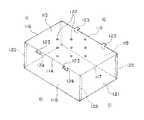
図1は、包装用容器内に巨峰を収容した状態を示し、図中符号10は包装用容器、符号Aは収容物たる巨峰である。  FIG. 1 shows a state in which a giant peak is accommodated in a packaging container. In the figure,reference numeral 10 denotes a packaging container, and reference numeral A denotes a giant peak as a container.

包装用容器10は、下方が開口した箱状の透明な透視カバー11と、透視カバー11の開口部縁に嵌り込む戴置トレー12と、透視カバー11が嵌まり込む包装用外箱13とを備え、透視カバー11を通して収容物を透視可能なように収容できるようになっている。  Thepackaging container 10 includes a box-shaped transparent see-throughcover 11 opened at the bottom, a placingtray 12 fitted into the opening edge of the see-throughcover 11, and anouter packaging box 13 into which the see-throughcover 11 is fitted. It can be accommodated so that the contents can be seen through the see-throughcover 11.

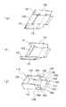
透視カバー11は、図2に示すように、カバー天板14と、カバー天板14の四辺に折り目15〜18を介して一体に形成されたカバー前側板19、カバー背側板20、カバー左側板21及びカバー右側板22とを備え、弾性を有する透明なプラスッチック板材を図3に示す展開図のように打ち抜き、それを組み立てることにより下方が開口した箱状に形成されている。  As shown in FIG. 2, the see-throughcover 11 includes a covertop plate 14, a coverfront side plate 19, a cover backside plate 20, and a cover left side plate integrally formed on four sides of the covertop plate 14 viafolds 15 to 18. 21 and the coverright side plate 22, a transparent plastic plate material having elasticity is punched out as shown in a development view shown in FIG. 3, and is assembled into a box shape having an opening at the bottom.

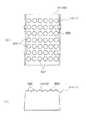
カバー天板14は、平板状に形成され、その表面に複数の通気孔23,23…を備え、前側及び背側の外周縁に水平方向に突出した係止突片24,24…を備えている。  The covertop plate 14 is formed in a flat plate shape, and has a plurality of vent holes 23, 23... On its surface, and lockingprotrusions 24, 24. Yes.

係止突片24は、折り目15,16の外側にコ字状の切れ目25を設けること、即ちカバー前側板19及びカバー背側板20の天板側縁部にコ字状の切れ目25を設けることによって形成され、カバー前側板19及びカバー背側板20を折り目15,16を介して折り曲げた際にカバー天板14と水平方向で連続して突出するようになっている。  The lockingprotrusion 24 is provided with aU-shaped cut 25 on the outside of thefolds 15, 16, that is, aU-shaped cut 25 is provided at the top side edge of the coverfront side plate 19 and the cover backside plate 20. When the coverfront side plate 19 and the cover backside plate 20 are folded through thefolds 15 and 16, the covertop plate 14 and the covertop plate 14 are projected in a horizontal direction.

カバー前側板19及びカバー背側板20は、カバー天板14と折り目15,16を介して連続した長方形状に形成され、その両側縁には、折り目を介して糊しろ26,26が一体に形成され、この糊しろ26がカバー左側板21及びカバー右側板22の両側縁に接着されるようになっている。  The coverfront side plate 19 and the cover backside plate 20 are formed in a continuous rectangular shape through the covertop plate 14 and thefolds 15 and 16, and themargins 26 and 26 are integrally formed on both side edges through the folds. Themargin 26 is adhered to both side edges of the cover leftside plate 21 and the coverright side plate 22.

また、カバー前側板19及びカバー背側板20には、係止用孔27がカバー前側板19及びカバー背側板20の下縁部をスリット状に切り欠くことにより形成され、その両側縁には、連続して切れ目28,28が形成されている。  Also, the coverfront side plate 19 and the cover backside plate 20 are formed with a lockinghole 27 by cutting out the lower edge portions of the coverfront side plate 19 and the cover backside plate 20 in a slit shape. Thecuts 28 and 28 are continuously formed.

また、この係止用孔27の切れ目28の端部からカバー前側板19、カバー背側板20の折り目15,16とは反対側、即ちカバー天板14とは反対側の縁部に向かって斜めに折り目28a,28aが形成されている。  In addition, the edge of thecut hole 28 of the lockinghole 27 is slanted toward the edge of the coverfront side plate 19 and the cover backside plate 20 opposite to thefolds 15 and 16, that is, toward the edge opposite to the covertop plate 14. Thefolds 28a, 28a are formed in the upper part.

この折り目28a,28aに沿って、カバー前側板19及びカバー背側板20の縁部を内側若しくは外側に折り曲げることにより、係止用孔27の開口角度を後述するトレー係止用片36が挿入し易い角度に調整することができるようになっている。  By bending the edges of the coverfront side plate 19 and the cover backside plate 20 inward or outward along thefolds 28a, 28a, atray locking piece 36, which will be described later, is inserted into the opening angle of the lockinghole 27. It can be adjusted to an easy angle.

この透視カバー11は、カバー前側板19、カバー背側板20、カバー左側板21及びカバー右側板22をそれぞれ折り目15〜18より下側に折り曲げ、カバー前側板19及びカバー背側板20の側辺より折り曲げた糊しろ26をそれぞれカバー左側板21又はカバー右側板22の各側辺に接着剤等によって接着し、各側辺間を連結することによって、下方が開口した中空箱状に形成されるようになっている。  The see-throughcover 11 has a coverfront side plate 19, a cover backside plate 20, a coverleft side plate 21 and a coverright side plate 22 which are bent below thefolds 15 to 18, respectively, and from the sides of the coverfront side plate 19 and the cover backside plate 20. The foldedmargin 26 is adhered to each side of the cover leftside plate 21 or the coverright side plate 22 with an adhesive or the like, and the sides are connected to form a hollow box shape having an open bottom. It has become.

戴置トレー12は、図4に示すように、段ボール紙やボール紙等からなる紙板材の表面にラミネート層29を介してシート状の緩衝材30を一体的に貼り付けたものを図5に示す展開図のように打ち抜き、それを折曲加工することによって皿状に形成され、緩衝材30の上に巨峰等の収容物Aを戴置するようになっている。  As shown in FIG. 4, theloading tray 12 is obtained by integrally attaching a sheet-like cushioning material 30 to a surface of a paper board material made of corrugated paper or cardboard via alaminate layer 29 as shown in FIG. It is formed into a dish shape by punching out as shown in the developed view and bending it, and a container A such as a giant peak is placed on thecushioning material 30.

この戴置トレー12は、平板状のトレー底板31と、トレー底板31の四辺に折り目を介して一体に形成されたトレー前側板32、トレー背側板33、トレー左側板34及びトレー右側板35とを備えて構成されている。  Theloading tray 12 includes a flat traybottom plate 31, a trayfront side plate 32, a tray backside plate 33, a trayleft side plate 34, and a trayright side plate 35 integrally formed on the four sides of thetray bottom plate 31 through folds. It is configured with.

トレー前側板32及びトレー背側板33は、トレー底板31に折り目を介して連続して、その折り目とは反対側の縁部が広い台形状に形成されている。  The trayfront side plate 32 and the tray backside plate 33 are formed in a trapezoidal shape that is continuous with thetray bottom plate 31 through a fold, and has a wide edge on the opposite side to the fold.

またトレー前側板32及びトレー背側板33の折り目とは反対側の縁部には、透視カバー11の前背側板の下端部に形成された係止用孔27に係止される係止用突片36が一体に形成され、トレー前側板32及びトレー背側板33の両側縁には、折り目を介してトレー左側板34又はトレー右側板35の内側面に接着される接着板37,37が一体に形成されている。  Further, on the edge of the trayfront side plate 32 and the tray backside plate 33 opposite to the fold line, the locking protrusions to be locked in the locking holes 27 formed in the lower end portion of the front side plate of thefluoroscopic cover 11. Apiece 36 is integrally formed, andadhesive plates 37, 37 that are bonded to the inner side surface of the tray leftside plate 34 or the trayright side plate 35 through folds are integrally formed on both side edges of the trayfront side plate 32 and the tray backside plate 33. Is formed.

係止用突片36は、係止用孔27に挿入しやすいように先端部が円形状に形成され、その両側部には、係止用孔27の側縁部に係止される鉤状の突起が形成されている。  The front end of the lockingprotrusion 36 is formed in a circular shape so that it can be easily inserted into the lockinghole 27, and a hook-like shape that is locked to the side edge of the lockinghole 27 on both sides thereof. The protrusion is formed.

緩衝材30は、不織布、スポンジ状の発泡ポリエチレン等の柔らかい素材をもって形成されている。  Thebuffer material 30 is formed of a soft material such as a nonwoven fabric or sponge-like foamed polyethylene.

また、緩衝材30は、図6に示すように、その表面に収容物の形状に合わせた凹部30aを備えてもよく、巨峰の場合には、緩衝材30の表面に丸い実が収まる複数の半球形状の凹部30a、30a…が形成され、その凹部30aに実を収め、運搬時等に収容物がずれるのを防止するとともに、実を柔らかく包むように保護するようになっている。  In addition, as shown in FIG. 6, the cushioningmaterial 30 may include a concave portion 30 a that matches the shape of the contained material on the surface. In the case of a giant peak, the cushioningmaterial 30 has a plurality of round fruits that fit on the surface. The hemispherical recesses 30a, 30a,... Are formed, and the fruit is stored in the recesses 30a, so that the contents are prevented from shifting during transportation and the fruit is protected so as to be wrapped softly.

この戴置トレー12は、トレー底板31に対して各側板を立ち上げ、接着板37,37をそれぞれトレー左側板34及びトレー右側板35の内面に接着させることによって、トレー前側板32とトレー左側板34、トレー前側板32とトレー右側板35、トレー背側板33とトレー左側板34、トレー背側板33とトレー右側板35の各側板の側辺部間を連結し、皿状に形成されるようになっている。  Theloading tray 12 raises each side plate with respect to thetray bottom plate 31 and adheresadhesive plates 37 and 37 to the inner surfaces of the tray leftside plate 34 and the trayright side plate 35, respectively. Theplate 34, the trayfront side plate 32 and the trayright side plate 35, the tray backside plate 33 and the tray leftside plate 34, and the side portions of the side plates of the tray backside plate 33 and the trayright side plate 35 are connected to form a dish shape. It is like that.

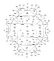
包装用外箱13は、段ボール紙やボール紙等からなる板状材を図8に示す展開図のように打ち抜き、それを折曲加工することにより形成されている。  Theouter packaging box 13 is formed by punching a plate-like material made of corrugated paper, cardboard, or the like as shown in a development view shown in FIG. 8, and bending it.

この包装用外箱13は、四角形の外箱底板38と、外箱底板38の前背左右の縁部にそれぞれ折り目39〜42を介して一体に形成された外箱前側板43、外箱背側板44、外箱左側板45及び外箱右側板46と、外箱前側板43と外箱左側板45の各側辺部を連結する前左側板間連結板47と、外箱前側板43と外箱右側板46の各側辺部を連結する前右側板間連結板48と、外箱背側板44と外箱左側板45の各側辺部を連結する背左側板間連結板49と、外箱背側板44と外箱右側板46の各側辺部を連結する背右側板間連結板50と、外箱左側板45及び外箱右側板46の上縁部にそれぞれ折り目を介して一体に形成された左頂板51及び右頂板52とを備えている。  The packagingouter box 13 includes a rectangular outerbox bottom plate 38, an outer boxfront side plate 43 integrally formed on the front left and right edges of the outerbox bottom plate 38 viafolds 39 to 42, and an outer box back plate.Side plate 44, outer box leftside plate 45 and outer boxright side plate 46, front left sideplate connecting plate 47 that connects each side of outer boxfront side plate 43 and outer box leftside plate 45, and outer box front side plate 43 A front right sideplate connecting plate 48 for connecting each side portion of the outer caseright side plate 46, a back left sideplate connecting plate 49 for connecting each side side portion of the outer case backside plate 44 and the outer case leftside plate 45; The back right sideplate connecting plate 50 that connects each side of the outer case backside plate 44 and the outer caseright side plate 46, and the upper edge of the outer case leftside plate 45 and the outer caseright side plate 46 are integrated with each other through a crease. The lefttop plate 51 and the righttop plate 52 are provided.

外箱前側板43は、長方形状に形成され、外箱底板38と折り目39を介して連続した前外側板53と、その折り目39とは反対側の縁部に前上縁板54を介して一体に形成された前内側板55とをもって構成され、前上縁板54の両縁部を折り目として折り曲げることにより、前内側板55を前外側板53に重ね合わせ、前内側板55を前外側板53の内側面に接着剤により固着させている。  The outer boxfront side plate 43 is formed in a rectangular shape, and is connected to the frontouter side plate 53 via the outerbox bottom plate 38 and thefold 39, and the edge on the opposite side of thefold 39 through the frontupper edge plate 54. The frontinner plate 55 is integrated with the frontinner side plate 55. The frontinner side plate 55 is overlapped with the frontouter side plate 53 by bending both edges of the frontupper edge plate 54 as folds. Theplate 53 is fixed to the inner surface with an adhesive.

外箱背側板44は、長方形状に形成され、外箱底板38と折り目40を介して連続した背外側板56と、その折り目40とは反対側の縁部に背上縁板57を介して一体に形成された背内側板58とをもって構成され、背上縁板57の両縁部を折り目として折り曲げて背内側板58を背外側板56の内側面に重ね合わせ、背内側板58を背外側板56の内側面に接着剤により固着させている。  The outer box backside plate 44 is formed in a rectangular shape, and is connected to the outer sidebottom plate 38 via the outerbox bottom plate 38 and thefold line 40, and the edge on the opposite side of thefold line 40 via the backupper edge plate 57. The backinner plate 58 is integrally formed, and is folded with both edges of the backupper edge plate 57 as creases, and the backinner plate 58 is overlapped with the inner surface of the backouter plate 56, and the backinner plate 58 is overlapped with the backinner plate 58. Theouter plate 56 is fixed to the inner side surface with an adhesive.

また、前内側板55及び背内側板58には、その側縁基端側より先端縁側に斜めに向けた折り目59を形成して該折り目59より折り畳まれる逃がし片部60,60を備えている。  Further, the frontinner plate 55 and the backinner plate 58 are provided withrelief pieces 60, 60 that are formed withfolds 59 obliquely directed from the side edge base end side to the tip edge side and are folded from thefolds 59. .

逃がし片部60の外側板とは反対側の縁部には、外箱底板38の前側部の折り目39より前上縁板54の幅分だけ内側に寄せた位置又は背側部の折り目40より背上縁板57の幅分だけ内側に寄せた位置に形成された係止孔61に係止される下側係止突起62が形成され、逃がし片部60の側縁、即ち内側板55,58の両側縁には、外箱左側板45又は外側右側板46の縁部に形成された係止孔63,63に係合する側縁係止突起64,64が形成されている。また、逃がし片部60の中央部分には、箱を解体する際に、逃がし片部60が容易に引き起こせるように、指穴65が設けられている。  At the edge of theescape piece 60 opposite to the outer side plate, from the front side fold 39 of the outerbox bottom plate 38, the position close to the inside by the width of the frontupper edge plate 54, or from the back side fold 40 Alower locking projection 62 is formed to be locked to alocking hole 61 formed at a position closer to the inside by the width of the backupper edge plate 57, and the side edge of therelief piece 60, that is, theinner plate 55, Sideedge locking projections 64, 64 that engage with lockingholes 63, 63 formed at the edge of the outer box leftside plate 45 or the outerright side plate 46 are formed on both side edges of the 58. Also, afinger hole 65 is provided in the central portion of therelief piece 60 so that therelief piece 60 can be easily caused when the box is disassembled.

また、前内側板55及び背内側板58には、上縁板54,57とは反対側の縁部に係止片回避用の切欠66が形成されている。  Further, the frontinner plate 55 and the backinner plate 58 are formed withnotches 66 for engaging piece avoidance at the edge opposite to theupper edge plates 54 and 57.

前上縁板54及び背上縁板57は、一定幅を有する細長板状に形成され、外箱前側板43又は外箱背側板44の上縁部を構成している。  The frontupper edge plate 54 and the backupper edge plate 57 are formed in an elongated plate shape having a constant width, and constitute the upper edge portion of the outer boxfront side plate 43 or the outer box backside plate 44.

この上縁板54,57には、左右頂板51,52の側縁に形成される係止片67が挿入される係止孔68が形成されている。  Theupper edge plates 54 and 57 are formed with lockingholes 68 into which lockingpieces 67 formed on the side edges of the left and righttop plates 51 and 52 are inserted.

外箱左側板45は、外箱底板38と折り目41を介して連続して形成され、外箱底板38とは反対側の縁部に折り目69を介して左頂板51が連続して形成されている。  The outer box leftside plate 45 is continuously formed through the outerbox bottom plate 38 and the fold line 41, and the lefttop plate 51 is continuously formed through thefold line 69 at the edge opposite to the outerbox bottom plate 38. Yes.

外箱右側板46は、外箱底板38と折り目42を介して連続して形成され、外箱底板38とは反対側の縁部に折り目70を介して右頂板52が連続して形成されている。  The outer boxright side plate 46 is continuously formed through the outerbox bottom plate 38 and thefold line 42, and the righttop plate 52 is continuously formed through thefold line 70 at the edge opposite to the outerbox bottom plate 38. Yes.

また、外箱左側板45及び外箱右側板46の両側縁には、前内側板55又は背内側板58の側縁に設けられた側縁係止突起64が係合されるように係合用の係止孔63が設けられている。  Further, the sideedge locking projections 64 provided on the side edges of the frontinner side plate 55 or the backinner side plate 58 are engaged with both side edges of the outer case leftside plate 45 and the outer caseright side plate 46 for engagement. A lockinghole 63 is provided.

左頂板51及び右頂板52には、その両側辺端部に折り目を介して係止片67,67が一体に形成されており、この係止片67が前側板43及び背側板44の上縁、即ち前上縁板54及び背上縁板57上に形成された係止孔68,68に挿入されて係止されることによって、左右頂板51,52がそれぞれ包装用外箱の上面端部で外箱前側板43と外箱背側板44との間に掛け渡されて固定される。  The lefttop plate 51 and the righttop plate 52 are integrally formed with lockingpieces 67 and 67 through folds at both side edges, and the lockingpieces 67 are the upper edges of thefront side plate 43 and theback side plate 44. In other words, the left and righttop plates 51 and 52 are respectively inserted into the locking holes 68 and 68 formed on the frontupper edge plate 54 and the backupper edge plate 57 and locked, so that the left and righttop plates 51 and 52 are respectively the upper end portions of the packaging outer box. Then, it is stretched between the outer boxfront side plate 43 and the outer box backside plate 44 and fixed.

前左側板間連結板47、前右側板間連結板48、背左側板間連結板49及び背右側板間連結板50は、それぞれ折り目71を介して固定部72と可動部73とから構成されている。  The front left sideplate connecting plate 47, the front right sideplate connecting plate 48, the back left sideplate connecting plate 49, and the back right sideplate connecting plate 50 are each composed of a fixedportion 72 and amovable portion 73 via afold 71. ing.

前左側板間連結板47、前右側板間連結板48、背左側板間連結板49及び背右側板間連結板50は、固定部72が接着剤をもって前外側板53及び背外側板56の内面に接着され、組み立てられた際に、各連結板47,48,49,50の固定部72と可動部73とが重なり合った部分の一部が内側板55,58により押さえられるようになっている。  The front left sideplate connecting plate 47, the front right sideplate connecting plate 48, the back left sideplate connecting plate 49, and the back right sideplate connecting plate 50 are fixed to the frontouter plate 53 and the backouter plate 56 with the fixingportion 72 having an adhesive. A part of the overlapping portion of the fixedportion 72 and themovable portion 73 of each connectingplate 47, 48, 49, 50 is pressed by theinner plates 55, 58 when bonded to the inner surface and assembled. Yes.

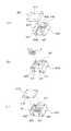
次に、上述した包装用外箱13の組立方法について図9、図10を参照して説明する。  Next, the assembly method of the packagingouter box 13 will be described with reference to FIGS.

まず、図9(a)〜(b)に示すように、折り目41に沿って外箱左側板45を内側、即ち底板側に折り曲げ、外箱左側板45と連続した左頂板51とともに外箱底板38に重ねて折り畳む。そして、そのとき一緒に折られる各連結板47,49の固定部72を前外側板53及び背外側板56の重なり合った部分に接着剤等によって貼着させる。  First, as shown in FIGS. 9A to 9B, the outer box leftside plate 45 is bent inward, that is, the bottom plate side along the fold line 41, and the outer box bottom plate is continuous with the lefttop plate 51 continuous with the outer box leftside plate 45. Fold it over 38. And the fixing | fixedpart 72 of eachconnection board 47 and 49 folded together at that time is affixed on the overlap part of the frontouter side board 53 and the backouter side board 56 with an adhesive agent.

同様に、図9(b)〜(c)に示すように、折り目42に沿って外箱右側板46を内側、即ち底板側に折り曲げ、外箱右側板46と連続した右頂板52とともに外箱底板38に重ねて折り畳む。そして、そのとき一緒に折られる各連結板48,50の固定部72を前外側板53及び背外側板56の重なり合った部分に接着剤等によって貼着させる。  Similarly, as shown in FIGS. 9B to 9C, the outer caseright side plate 46 is folded inward along thefold line 42, that is, the bottom plate side, and the outer case together with the righttop plate 52 continuous with the outer caseright side plate 46. Fold over thebottom plate 38. And the fixing | fixedpart 72 of eachconnection board 48 and 50 folded together at that time is affixed on the overlap part of the frontouter side board 53 and the backouter side board 56 with an adhesive agent.

このように各連結板47,48,49,50の固定部72を前外側板53及び背外側板56の重なり合った部分に貼着させたことにより、外箱前側板43及び外箱背側板44を立ち上げると貼着された連結板47,48,49,50に連動して外箱左側板45及び外箱右側板46も立ち上がるようになっている。  In this way, by fixing the fixingportions 72 of the connectingplates 47, 48, 49, 50 to the overlapping portions of the frontouter plate 53 and the backouter plate 56, the outer boxfront side plate 43 and the outer box backside plate 44. The outer box leftside plate 45 and the outer boxright side plate 46 are also raised in conjunction with the attached connectingplates 47, 48, 49, 50.

そして、図9(c)〜(d)に示すように、前内側板55を前上縁板54の両縁を折り目として折り曲げ、前外側板53に重ね合わせ、重なり合った前内側板55を前外側板53の内側面に貼着させ、背内側板58を同様に背上縁板57の両縁部を折り目として折り、背外側板56に重ね合わせ、重なり合った背内側板58を背外側板56の内側面に貼着させる。  Then, as shown in FIGS. 9C to 9D, the frontinner side plate 55 is folded with both edges of the frontupper edge plate 54 as folds, overlapped with the frontouter side plate 53, and the overlapped frontinner side plate 55 is moved forward. The backinner plate 58 is similarly attached to the inner side surface of theouter plate 53, folded in the same manner with both edges of the backupper edge plate 57 as creases, overlapped with the backouter plate 56, and the overlapped backinner plate 58 is overlapped with the back outer plate. It is made to stick on the inner surface of 56.

このとき、前内側板55及び背内側板58に形成された係止片回避用切欠66により、左頂板51の側縁に形成された係止片67,67は、内側板55,58により押さえ込まれないようになっている。  At this time, the lockingpieces 67 and 67 formed on the side edge of the lefttop plate 51 are pressed by theinner plates 55 and 58 by the lockingpiece avoiding notches 66 formed on the frontinner plate 55 and the backinner plate 58. It is supposed not to be.

これで一次組立が終了し、組立中間部材80が形成され、この状態で、運搬や保管等を行えば、平板状であるので重ねても嵩張らず効率がよい。  In this state, the primary assembly is completed, and the assemblyintermediate member 80 is formed. If transportation and storage are performed in this state, the plate is in the shape of a flat plate so that it is efficient without being bulky.

次に、この組立中間部材80を図10(e)〜(f)に示すように、前側板43及び背側板44を立ち上げると、各連結板47,48,49,50が連動して、外箱左側板45及び外箱右側板46も立ち上がる。このとき逃がし片部60を立ち上げることにより、連結板47,48,49,50が前背内側板55,58に邪魔されずに好適に作動する。  Next, as shown in FIGS. 10E to 10F, when thefront side plate 43 and theback side plate 44 are raised, the connectingplates 47, 48, 49, and 50 are interlocked. The outer box leftside plate 45 and the outer boxright side plate 46 also rise. At this time, by raising therelief piece 60, the connectingplates 47, 48, 49, 50 are preferably operated without being obstructed by the front backinner plates 55, 58.

そして、図10(f)〜(g)に示すように、外箱前側板43、外箱背側板44、外箱左側板45及び外箱右側板46を外箱底板38に対して立ち上げ、逃がし片部60,60を元に戻して、前内側板55及び背内側板58の両側縁に形成された側縁係止突起64を外箱左側板45及び外箱右側板46の係止孔63,63に係合させ、連結板47,48,49,50の固定部72と可動部73とが重なり合った部分を、前外側板53と前内側板55との間、或いは背外側板56と背内側板58との間で挟持する。  10 (f) to (g), the outer boxfront side plate 43, the outer box backside plate 44, the outer box leftside plate 45 and the outer boxright side plate 46 are raised with respect to the outerbox bottom plate 38, Theescape piece portions 60, 60 are returned to their original positions, and the sideedge locking projections 64 formed on both side edges of the frontinner plate 55 and the backinner plate 58 are used as locking holes in the outer box leftplate 45 and the outer boxright plate 46. 63, 63 is engaged, and the portion of the connectingplates 47, 48, 49, 50 where the fixedportion 72 and themovable portion 73 overlap is located between the frontouter plate 53 and the frontinner plate 55 or the backouter plate 56. And the backinner plate 58.

図10(g)〜(h)に示すように、左頂板51及び右頂板52を内側へ折り曲げ、両側縁の係止片67を係止孔68に挿入して係合させることにより、包装用外箱13が形成される。  As shown in FIGS. 10G to 10H, the lefttop plate 51 and the righttop plate 52 are bent inward, and the lockingpieces 67 on both side edges are inserted into the locking holes 68 to engage with each other. Anouter box 13 is formed.

この包装用容器10を用いて巨峰等の収容物Aを包装するには、まず、図11(a)〜図11(b)に示すように、透視カバー11を開口部を上に向けておき、カバー前側板19の係止用孔27に戴置トレー12のトレー背側板側の係止用突片36を挿入し、透視カバー11と戴置トレー12とが係止用突片36と係止用孔27との連結部分を蝶番のようにした状態にしておく。  In order to wrap the container A such as Kyoho using thepackaging container 10, first, as shown in FIGS. 11 (a) to 11 (b), thefluoroscopic cover 11 is directed upward. Then, a lockingprojection piece 36 on the tray back side plate side of the mountingtray 12 is inserted into the lockinghole 27 of the coverfront side plate 19, and thefluoroscopic cover 11 and the mountingtray 12 are engaged with the lockingprojection piece 36. The connecting portion with thestop hole 27 is in the state of a hinge.

このとき、折り目28aよりカバー前側板19の側縁部を外側に折り曲げておくことによって、透視カバー11の係止用孔27が係止用突片36を挿入し易い角度に開口するようになっている。  At this time, by folding the side edge of the coverfront side plate 19 outward from thefold 28a, the lockinghole 27 of thefluoroscopic cover 11 opens at an angle at which the lockingprotrusion 36 can be easily inserted. ing.

その状態で図11(b)〜図11(c)に示すように、透視カバー11内に収容物Aを開口部より挿入した後、係止用突片36と係止用孔27との連結部分を蝶番のようにして戴置トレー12を回転させて開口部に蓋をし、前側板側の係止用突片36をカバー背側板20の内側から係止用孔27に挿入させ係合させる。  In this state, as shown in FIGS. 11 (b) to 11 (c), after the container A is inserted into thefluoroscopic cover 11 from the opening, the lockingprotrusion 36 and the lockinghole 27 are connected. Theloading tray 12 is rotated like a hinge to cover the opening, and the lockingprotrusion 36 on the front plate side is inserted into the lockinghole 27 from the inside of the cover backplate 20 to engage. Let

このとき、折り目28aよりカバー背側板20の側縁部を内側に折り曲げておくことによって、透視カバー11の係止用孔27が係止用突片36を挿入し易い角度に開口するようになっている。  At this time, by folding the side edge of the cover backplate 20 inward from thefold 28a, the lockinghole 27 of thefluoroscopic cover 11 opens at an angle at which the lockingprotrusion 36 can be easily inserted. ing.

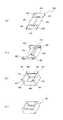
次に、図12(d)に示すように、左頂板51及び右頂板52を立ち上げた状態の包装用外箱13を開口部を下にして戴置トレー12を被せた透視カバー11の上側、即ち戴置トレー側より被せ、包装用外箱13内に戴置トレー12及び透視カバー11を挿入し、図12(e)〜図12(f)に示すように、透視カバー11を手で押さえながら透視カバー11及び包装用外箱13を透視カバー11が上面に露出するようにひっくり返す。  Next, as shown in FIG. 12 (d), the upper side of thefluoroscopic cover 11 in which the packagingouter box 13 with the lefttop plate 51 and the righttop plate 52 raised is covered with theloading tray 12 with the opening portion down. In other words, the placingtray 12 and the see-throughcover 11 are inserted into theouter packaging box 13 from the placing tray side, and the see-throughcover 11 is manually placed as shown in FIGS. While holding down, thefluoroscopic cover 11 and the packagingouter box 13 are turned over so that thefluoroscopic cover 11 is exposed on the upper surface.

このようにひっくり返した後、図12(f)〜図12(g)に示すように、包装用外箱13の左頂板51及び右頂板52を折り目より折り曲げるとともに、係止片67を外箱前側板上縁54及び外箱背側板上縁57の係止孔68に係合させ、透視カバー11を通して収容物Aを透視可能なように包装が完了する。  After turning over like this, as shown in FIGS. 12 (f) to 12 (g), the lefttop plate 51 and the righttop plate 52 of theouter packaging box 13 are folded from the folds, and thelocking piece 67 is moved to the outer box. The packaging is completed so that the contents A can be seen through the see-throughcover 11 by engaging with the locking holes 68 of theupper edge 54 of the front plate and theupper edge 57 of the outer case back side plate.

尚、この包装用容器10は、図11(a)〜図11(c)までの工程を上述の実施例と同様に行い、透視カバー11内に収容物Aを収容し、開口部を戴置トレーにより閉鎖した状態とした後、図13(h)〜図13(i)に示すように、透視カバー11及び戴置トレー12を透視カバー11を手で押さえながらひっくり返して表向きにし、それを図13(j)に示すように、左頂板51及び右頂板52を立ち上げた包装用外箱13の上側、即ち開口部からを挿入し、包装用外箱13内に戴置トレー12及び透視カバー11を収容させ、それを図13(k)に示すように、包装用外箱13の左頂板51及び右頂板52を折り目より折り曲げるとともに、係止片67を包装用外箱の前上縁板54及び背上縁板57の係止孔68に係合させることによっても、透視カバー11を通して収容物Aを透視可能なように包装することができる。  In thispackaging container 10, the steps from FIG. 11 (a) to FIG. 11 (c) are performed in the same manner as in the above-described embodiment, and the container A is accommodated in thefluoroscopic cover 11, and the opening is placed. After being closed by the tray, as shown in FIGS. 13 (h) to 13 (i), thefluoroscopic cover 11 and the placingtray 12 are turned upside down while holding thefluoroscopic cover 11 by hand, As shown in FIG. 13 (j), the lefttop plate 51 and the righttop plate 52 are inserted up the upper side of the packagingouter box 13, that is, from the opening, and the placingtray 12 and the perspective view are inserted into the packagingouter box 13. As shown in FIG. 13 (k), thecover 11 is accommodated, and the lefttop plate 51 and the righttop plate 52 of theouter packaging box 13 are folded from the fold, and thelocking piece 67 is placed at the front upper edge of the outer packaging box. Engaging with the locking holes 68 of theplate 54 and the backupper edge plate 57 What can also be packaged contained goods A throughfluoroscopy cover 11 so as to be transparent.

一方、この包装用容器10より収容物Aを取り出すには、係止片67を外箱前側板43及び外箱背側板44上縁の係止孔68より取り外し、左頂板51及び右頂板52を立ち上げ、透視カバー11を係止突片24,24を掴んで持上げる。  On the other hand, in order to take out the contents A from thepackaging container 10, the lockingpiece 67 is removed from the locking holes 68 on the upper edge of the outer boxfront side plate 43 and the outer box backside plate 44, and the lefttop plate 51 and the righttop plate 52 are removed. Start up and lift up thefluoroscopic cover 11 by grasping the lockingprojections 24, 24.

このようにすると、収容物Aの重量により、戴置トレー12の係止用突片36が透視カバー11の係止用孔27より外れ、透視カバー11だけが持ち上がるので、包装用外箱13内に戴置トレー12に載せられた状態で収容物Aが残り、容易に取り出すことができるようになる。  In this way, the lockingprotrusions 36 of theloading tray 12 are disengaged from the locking holes 27 of thefluoroscopic cover 11 due to the weight of the contents A, and only thefluoroscopic cover 11 is lifted. The contents A remain on theloading tray 12 and can be easily taken out.

次に、本発明に係る包装用容器の他の実施の形態を図14〜図20について説明する。  Next, another embodiment of the packaging container according to the present invention will be described with reference to FIGS.

この包装用容器110は、図14に示すように、下方が開口した箱状の透明な透視カバー111と、透視カバー111が内部に嵌まり込む包装用外箱112とを備え、透視カバー111を通して収容物Aを透視可能なように収容できるようになっている。  As shown in FIG. 14, thepackaging container 110 includes a box-shaped transparent see-through cover 111 opened at the bottom and anouter packaging box 112 into which the see-through cover 111 is fitted. The container A can be accommodated so as to be seen through.

透視カバー111は、図15に示すように、カバー天板113と、カバー天板113の四辺に折り目114〜117を介して一体に形成されたカバー前側板118、カバー背側板119、カバー左側板120及びカバー右側板121とを備え、弾性を有する透明なプラスッチック板材を展開した状態で打ち抜き、それを組み立てることにより下方が開口した箱状に形成されている。  As shown in FIG. 15, the fluoroscopic cover 111 includes a covertop plate 113, a coverfront side plate 118, a cover backside plate 119, and a cover left side plate integrally formed on the four sides of the covertop plate 113 viafold lines 114 to 117. 120 and a coverright side plate 121 are formed in a box shape having an opening at the bottom by punching out a transparent plastic plate material having elasticity and assembling it.

カバー天板113は、平板状に形成され、その表面に複数の通気孔122,122…を備え、前側及び背側の外周縁に水平方向に突出した係止突片123,123…を備えている。  The covertop plate 113 is formed in a flat plate shape, and has a plurality ofventilation holes 122, 122... On its surface, and lockingprotrusions 123, 123. Yes.

係止突片123は、折り目114,115の外側にコ字状の切れ目124を設けること、即ちカバー前側板118及びカバー背側板119の天板側縁部にコ字状の切れ目124を設けることによって形成され、カバー前側板118及びカバー背側板119を折り目114,115を介して折り曲げた際にカバー天板113と水平方向で連続して突出するようになっている。  The lockingprotrusion 123 is provided with aU-shaped cut 124 on the outer side of thefold lines 114, 115, that is, aU-shaped cut 124 is provided at the top plate side edge of the coverfront side plate 118 and the cover backside plate 119. When the coverfront side plate 118 and the cover backside plate 119 are bent through thefold lines 114 and 115, the covertop plate 113 and the covertop plate 113 are projected in a horizontal direction.

カバー前側板118及びカバー背側板119は、カバー天板113と折り目114,115を介して連続した長方形状に形成され、その両側縁には、折り目を介して糊しろ125,125が一体に形成され、この糊しろ125がカバー左側板120及びカバー右側板121の両側縁に接着されるようになっている。  The coverfront side plate 118 and the cover backside plate 119 are formed in a continuous rectangular shape through the covertop plate 113 and thefolds 114, 115, and themargins 125, 125 are integrally formed on both side edges through the folds. Themargin 125 is bonded to both side edges of the cover leftside plate 120 and the coverright side plate 121.

カバー左側板120及びカバー右側板121は、開口部側、即ち折り目116,117とは反対側の辺が広く形成された対称な台形状に形成されている。  The cover leftside plate 120 and the coverright side plate 121 are formed in a symmetrical trapezoidal shape in which the side on the opening side, that is, the side opposite to thefolds 116 and 117 is formed widely.

この透視カバー111は、カバー前側板118、カバー背側板119、カバー左側板120及びカバー右側板121をそれぞれ折り目114〜117より下側に折り曲げ、カバー前側板118及びカバー背側板119の側辺より折り曲げた糊しろ125をそれぞれカバー左側板120又はカバー右側板121の各側辺に接着剤等によって接着し、各側辺間を連結することによって、下方が開口した中空箱状に形成されるようになっている。  The see-through cover 111 has a coverfront side plate 118, a cover backside plate 119, a coverleft side plate 120, and a coverright side plate 121 that are bent below thefold lines 114 to 117, respectively, and from the sides of the coverfront side plate 118 and the cover backside plate 119. The foldedmargin 125 is adhered to each side of the cover leftside plate 120 or the coverright side plate 121 with an adhesive or the like, and the sides are connected to form a hollow box shape having an open bottom. It has become.

包装用外箱112は、段ボール紙やボール紙等からなる板状材を図17に示す展開図のように打ち抜き、それを折曲加工することにより形成されている。  The packagingouter box 112 is formed by punching a plate-like material made of corrugated paper, cardboard, or the like as shown in a development view shown in FIG. 17 and bending it.

この包装用外箱112は、四角形の外箱底板126と、外箱底板126の前背左右の縁部にそれぞれ折り目127〜130を介して一体に形成された外箱前側板131、外箱背側板132、外箱左側板133及び外箱右側板134と、外箱前側板131と外箱左側板133の各側辺部を連結する前左側板間連結板135と、外箱前側板131と外箱右側板134の各側辺部を連結する前右側板間連結板136と、外箱背側板132と外箱左側板133の各側辺部を連結する背左側板間連結板137と、外箱背側板132と外箱右側板134の各側辺部を連結する背右側板間連結板138とを備えている。  The packagingouter box 112 includes a rectangular outer boxbottom plate 126, an outer boxfront side plate 131 formed integrally with the front left and right edges of the outer boxbottom plate 126 viafold lines 127 to 130, and an outer box back plate.Side plate 132, outer box leftside plate 133 and outer boxright side plate 134, outer boxfront side plate 131, front left sideplate connecting plate 135 that connects each side part of outer box leftside plate 133, and outer box front side plate 131 A front right sideplate connecting plate 136 for connecting each side portion of the outer caseright side plate 134, a back left sideplate connecting plate 137 for connecting each side side portion of the outer case backside plate 132 and the outer case leftside plate 133, A back right sideplate connecting plate 138 that connects each side of the outer case backside plate 132 and the outer caseright side plate 134 is provided.

外箱前側板131は、長方形状に形成され、外箱底板126と折り目127を介して連続した前外側板139と、その折り目127とは反対側の縁部に前上縁板140を介して一体に形成された前内側板141とをもって構成され、前上縁板140の両縁部を折り目として折り曲げることにより、前内側板141を前外側板139に重ね合わせ、前内側板141の上縁板140とは反対側の縁部に形成された接着片142を前外側板139の内側面に接着剤により固着させている。  The outer boxfront side plate 131 is formed in a rectangular shape, and has a frontouter side plate 139 continuous through the outer boxbottom plate 126 and thefold 127, and a frontupper edge plate 140 at the edge opposite to thefold 127. The frontinner plate 141 is integrally formed, and the frontinner plate 141 is overlapped with the frontouter plate 139 by bending both edges of the frontupper edge plate 140 as folds, and the upper edge of the frontinner plate 141 is formed. Anadhesive piece 142 formed on the edge opposite to theplate 140 is fixed to the inner surface of the frontouter plate 139 with an adhesive.

外箱背側板132は、長方形状に形成され、外箱底板126と折り目128を介して連続した背外側板143と、その折り目128とは反対側の縁部に背上縁板144を介して一体に形成された背内側板145とをもって構成され、背上縁板144の両縁部を折り目として折り曲げて背内側板145を背外側板143の内側面に重ね合わせ、背内側板143の上縁板144とは反対側の縁部に形成された接着片146を背外側板143の内側面に接着剤により固着させている。  The outer box backside plate 132 is formed in a rectangular shape, and is connected to the outer sidebottom plate 126 and the backouter side plate 143 through thefold 128, and the edge on the opposite side of thefold 128 through the backupper edge plate 144. The backinner plate 145 is integrally formed, and is folded with both edges of the backupper edge plate 144 as folds, and the backinner plate 145 is superimposed on the inner side surface of the backouter plate 143, Anadhesive piece 146 formed on the edge opposite to theedge plate 144 is fixed to the inner surface of the backouter plate 143 with an adhesive.

接着片142,146は、内側板141,145の上縁板140,144と反対側の縁に切れ目147,147を入れるとともに、縁部と平行に折り目148,149を設けることにより形成され、折り目148,149で折り曲げ、折り目149を境に縁側のみを接着剤により側板の内側面に固着させる。このようにすることによって上縁板140,144の幅が広くとも、無理なく内側板141,145を前外側板139及び背外側板143に接合することができる。  Theadhesive pieces 142 and 146 are formed by makingcuts 147 and 147 at the edges opposite to theupper edge plates 140 and 144 of theinner plates 141 and 145 and providingfolds 148 and 149 in parallel with the edges. It is bent at 148, 149, and only the edge side is fixed to the inner side surface of the side plate with an adhesive at thefold line 149 as a boundary. By doing so, even if the width of theupper edge plates 140 and 144 is wide, theinner plates 141 and 145 can be joined to the frontouter plate 139 and the backouter plate 143 without difficulty.

また、前内側板141及び背内側板145の左側板側には、その側縁基端側より先端縁側に斜めに向けた折り目150を形成して該折り目150より折り畳まれる逃がし片部151を備えている。  Further, on the left side of the frontinner side plate 141 and the backinner side plate 145, there is provided arelief piece 151 that is folded from thecrease 150 by forming afold 150 that is inclined obliquely from the side edge base end side to the tip end side. ing.

逃がし片部151の側縁、即ち内側板141,145の両側縁には、外箱左側板133の縁部に形成された係止凹部152,152に係合する側縁係止突起153,153が形成されている。また、逃がし片部151の中央部分には、箱を解体する際に、逃がし片部151が容易に引き起こせるように、指穴154が設けられている。  Sideedge locking projections 153 and 153 that engage with lockingrecesses 152 and 152 formed on the edge of the outer case leftside plate 133 are formed on the side edges of theescape piece 151, that is, on both side edges of theinner plates 141 and 145. Is formed. In addition, afinger hole 154 is provided in the central portion of theescape piece 151 so that theescape piece 151 can be easily caused when the box is disassembled.

前上縁板140及び背上縁板144は、一定幅を有する細長板状に形成され、外箱前側板131又は外箱背側板132の上縁部を構成している。  The frontupper edge plate 140 and the backupper edge plate 144 are formed in an elongated plate shape having a constant width, and constitute an upper edge portion of the outer boxfront side plate 131 or the outer box backside plate 132.

また、前内側板141及び背内側板145の右側板側縁部には、折り目155を介して補強板156が一体に形成されている。  Further, a reinforcingplate 156 is integrally formed on the right side plate side edge portion of the frontinner plate 141 and the backinner plate 145 through afold 155.

外箱左側板133は、底板側が広い対称な台形に形成され、外箱底板126と折り目129を介して連続した左外側板157と、その折り目129とは反対側の縁部に左上縁板158を介して一体に形成された左内側板159とをもって構成され、左上縁板158の両縁部を折り目として折り曲げることにより、左内側板159を左外側板157に重ね合わせ、左内側板159を左外側板157の内側面に接着剤により固着させている。  The outer box leftside plate 133 is formed in a symmetrical trapezoidal shape with a wide bottom plate side, a leftouter plate 157 continuous through the outer boxbottom plate 126 and thefold line 129, and a leftupper edge plate 158 at an edge opposite to thefold line 129. The leftinner plate 159 is overlapped with the leftouter plate 157 by bending both edges of the upperleft edge plate 158 as folds. The leftouter plate 157 is fixed to the inner surface with an adhesive.

左内側板159の両側縁には、前内側板141又は背内側板145の側縁に設けられた側縁係止突起153が係合されるように係合用の係止凹部152が設けられている。  Engaging lockingrecesses 152 are provided on both side edges of the leftinner plate 159 so that sideedge locking projections 153 provided on the side edges of the frontinner plate 141 or the backinner plate 145 are engaged. Yes.

また、左内側板159の両側縁には、折り目160を介して補強片161,161が一体に形成されている。  Reinforcingpieces 161 and 161 are integrally formed on both side edges of the leftinner plate 159 via afold 160.

外箱右側板134は、底板側が広い対称な台形に形成され、外箱底板126と折り目130を介して連続して形成され、折り目130を軸として開閉可能な蓋として機能するようになっている。  The outer boxright side plate 134 is formed in a symmetrical trapezoidal shape with a wide bottom plate side, is formed continuously through the outer boxbottom plate 126 and thefold 130, and functions as a lid that can be opened and closed with thefold 130 as an axis. .

また、外箱右側板134には、外箱底板126とは反対側の縁部に右上縁板162を介して差込板163が連続して形成されている。  In addition, aninsertion plate 163 is continuously formed on the outer boxright side plate 134 via an upperright edge plate 162 at the edge opposite to the outer boxbottom plate 126.

差込板163の両側縁には、前内側板141及び背内側板145の左側縁に形成された係止凹部164と係合する係止突起165が一体に形成されている。  Lockingprojections 165 that engage with lockingrecesses 164 formed on the left side edges of the frontinner plate 141 and the backinner plate 145 are integrally formed on both side edges of theinsertion plate 163.

前左側板間連結板135及び背左側板間連結板137は、それぞれ折り目166を介して固定部167と可動部168とから構成されている。  The front leftinter-plate connection plate 135 and the back leftinter-plate connection plate 137 each include a fixedportion 167 and amovable portion 168 via afold line 166.

前左側板間連結板135及び背左側板間連結板137は、固定部167が接着剤をもって前外側板139及び背外側板143の内面に接着され、組み立てられた際に、各連結板135,137の固定部167と可動部168とが重なり合った部分の一部が内側板141,145により押さえられるようになっている。  When the front left sideplate connecting plate 135 and the back left sideplate connecting plate 137 are assembled, the fixingportion 167 is bonded to the inner surfaces of the frontouter plate 139 and the backouter plate 143 with an adhesive. A part of the portion where the fixedportion 167 and themovable portion 168 overlap each other is pressed by theinner plates 141 and 145.

前右側板間連結板136及び背右側板間連結板138は、底板の隅より斜めに向けた折り目169を備え、組み立てられた際に、折り目169を介して折り畳まれて、外箱右側板134と補強板156との間に挟み込まれるようになっている。  The front right sideplate connecting plate 136 and the back right sideplate connecting plate 138 include afold 169 that is inclined obliquely from the corner of the bottom plate. When assembled, the front right sideplate connecting plate 136 and the back right sideplate connecting plate 138 are folded via thefold 169. And the reinforcingplate 156.

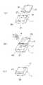
次に、上述した包装用外箱112の組立方法について図18、図19を参照して説明する。  Next, a method for assembling the packagingouter box 112 will be described with reference to FIGS.

まず、図18(a)〜(b)に示すように、左内側板159を左上縁板158の両縁を折り目として折り曲げ、左外側板157に重ね合わせ、重なり合った左内側板159を左外側板157の内側面に貼着させて外箱左側板133を形成する。  First, as shown in FIGS. 18A to 18B, the leftinner plate 159 is bent with both edges of the upperleft edge plate 158 as folds, and is overlapped with the leftouter plate 157, and the overlapping leftinner plate 159 is placed on the left outer plate. The outer box leftside plate 133 is formed by adhering to the inner side surface of theplate 157.

次に、図18(b)〜(c)に示すように、折り目129に沿って外箱左側板133を内側、即ち底板側に折り曲げ、外箱底板126に重ねて折り畳む。そして、そのとき一緒に折られる各連結板135,137の固定部167を前外側板139及び背外側板143の重なり合った部分に接着剤等によって貼着させる。  Next, as shown in FIGS. 18B to 18C, the outer case leftside plate 133 is bent inward, that is, on the bottom plate side along thefold line 129, and overlapped with the outer casebottom plate 126. And the fixing |fixed part 167 of each connection plate 135,137 folded together at that time is affixed on the overlap part of the frontouter side board 139 and the backouter side board 143 with an adhesive agent.

このように各連結板135,137の固定部167を前外側板139及び背外側板143の重なり合った部分に貼着させたことにより、外箱前側板131及び外箱背側板132を立ち上げると貼着された連結板135,137に連動して外箱左側板133も立ち上がるようになっている。  When the fixingportions 167 of the connectingplates 135 and 137 are attached to the overlapping portions of the frontouter plate 139 and the backouter plate 143 in this way, when the outer boxfront side plate 131 and the outer box backside plate 132 are raised. The outer box leftside plate 133 also rises in conjunction with the attached connectingplates 135 and 137.

そして、図18(c)〜(d)に示すように、前内側板141を前上縁板140の両縁を折り目として折り曲げ、前外側板139に重ね合わせ、重なり合った前内側板141の接着片142を前外側板139の内側面に貼着させ、背内側板145を同様に背上縁板144の両縁部を折り目として折り、背外側板143に重ね合わせ、重なり合った背内側板145の接着片146を背外側板143の内側面に貼着させる。  Then, as shown in FIGS. 18C to 18D, the frontinner side plate 141 is folded with both edges of the frontupper edge plate 140 as folds, overlapped with the frontouter side plate 139, and the overlapped frontinner side plate 141 is bonded. Thepiece 142 is attached to the inner side surface of the frontouter side plate 139, the backinner side plate 145 is similarly folded with both edges of the backupper edge plate 144 as folds, overlapped with the backouter side plate 143, and the overlapped backinner side plate 145 Theadhesive piece 146 is adhered to the inner surface of the backouter plate 143.

これで一次組立が終了し、組立中間部材170が形成され、この状態で、運搬や保管等を行えば、平板状であるので重ねても嵩張らず効率がよい。  In this state, the primary assembly is completed, and theintermediate assembly member 170 is formed. In this state, if transportation, storage, or the like is performed, the plate is in a flat shape and is efficient without being bulky.

次に、この組立中間部材170を図19(e)〜(f)に示すように、前側板131及び背側板132を立ち上げると、各連結板135,137が連動して外箱左側板133も立ち上がる。このとき逃がし片部151を立ち上げることにより、連結板135,137が前背内側板141,145に邪魔されずに好適に作動する。  Next, as shown in FIGS. 19 (e) to 19 (f), when thefront side plate 131 and theback side plate 132 are raised as shown in FIGS. 19 (e) to 19 (f), the connectingplates 135, 137 are interlocked and the outer box leftside plate 133. Also stand up. At this time, by raising theescape piece 151, the connectingplates 135 and 137 are preferably operated without being obstructed by the front backinner plates 141 and 145.

そして、図19(f)〜(g)に示すように、外箱前側板131、外箱背側板132及び外箱左側板133を外箱底板126に対して立ち上げ、逃がし片部151,151を元に戻して、前内側板141及び背内側板145の側縁に形成された側縁係止突起153を外箱左側板133の係止凹部152,152に係合させ、連結板135,137の固定部167と可動部168とが重なり合った部分を、前外側板139と前内側板141との間、或いは背外側板143と背内側板145との間で挟持し、箱の右側面が開いた状態の包装用外箱112が形成される。  Then, as shown in FIGS. 19 (f) to 19 (g), the outer casefront side plate 131, the outer case backside plate 132 and the outer case leftside plate 133 are raised with respect to the outer casebottom plate 126, and therelease pieces 151, 151 , The sideedge locking projections 153 formed on the side edges of the frontinner plate 141 and the backinner plate 145 are engaged with the locking recesses 152, 152 of the outer box leftside plate 133, and the connectingplate 135, The portion of 137 where the fixedportion 167 and themovable portion 168 overlap is sandwiched between the frontouter plate 139 and the frontinner plate 141 or between the backouter plate 143 and the backinner plate 145, and the right side surface of the box The packagingouter box 112 in a state where is opened is formed.

外箱右側板134は蓋として機能し、前背両補強板156,156を折り目155より内側に折り曲げた後、折り目130を回転軸として外箱右側板134を立ち上げると、前右側板間連結板136及び背右側板間連結板138が折り目169を介して折り畳まれ、外箱右側板134と補強板156との間に挟み込まれ、右上縁板162の両縁を折り目として差込板163を折り曲げ、補強板156の内側、即ち補強板156と箱内に嵌め込まれた透視カバー111のカバー右側板との間に差し込み、両側縁の係止突起165を前内側板及び前背側板に形成された係止凹部164に係止させることにより、包装用外箱112の右側面を閉じることができる。  The outer caseright side plate 134 functions as a lid. After the front and rear reinforcingplates 156 and 156 are folded inward from thefold 155, when the outer caseright side plate 134 is raised with thefold 130 as a rotation axis, the front right side plate is connected. Theplate 136 and the back right sideplate connecting plate 138 are folded through thefold 169 and sandwiched between the outer caseright side plate 134 and the reinforcingplate 156, and theinsertion plate 163 is formed with both edges of the upperright edge plate 162 as folds. Folded, inserted inside the reinforcingplate 156, that is, between the reinforcingplate 156 and the cover right side plate of the fluoroscopic cover 111 fitted in the box, and lockingprojections 165 on both side edges are formed on the front inner plate and the front back plate. The right side surface of the packagingouter box 112 can be closed by engaging thelocking recess 164.

次に、この包装用容器110を用いて収容物Aを包装する方法を巨峰を例に説明する。  Next, a method for packaging the contents A using thepackaging container 110 will be described using Kyoho as an example.

まず、図20(a)に示すように、透視カバー111を開口部を上にして置き、その中に巨峰Aを挿入する。  First, as shown to Fig.20 (a), the fluoroscopic cover 111 is set | placed with an opening part up, and the huge peak A is inserted in it.

次に、図20(b)に示すように、開口部に不織布や発泡ポリエチレンからなるスポンジ状の緩衝材171を被せ、包装用外箱112の右側面を開いた状態で開口部を下にしておき、その右側面より巨峰Aを収容した透視カバー111を逆さまのまま水平方向にスライドさせ包装用外箱112内に挿入する。  Next, as shown in FIG. 20 (b), the opening is covered with a sponge-like cushioning material 171 made of nonwoven fabric or foamed polyethylene, and the opening is faced down with the right side surface of theouter packaging box 112 opened. Then, the see-through cover 111 containing the giant peak A is slid horizontally from the right side surface and inserted into theouter packaging box 112.

このとき、透視カバー111のカバー左側板120及びカバー右側板121が台形状に形成されるとともに、包装用外箱112の外箱左側板133及び外箱右側板134が台形状に形成され、透視カバー111が包装用外箱112内に嵌り込むようになっているので、逆さまの状態でも透視カバー111が包装用外箱112より外れないようになっている。  At this time, the cover leftside plate 120 and the coverright side plate 121 of the fluoroscopic cover 111 are formed in a trapezoidal shape, and the outer box leftside plate 133 and the outer boxright side plate 134 of the packagingouter box 112 are formed in a trapezoidal shape. Since the cover 111 is fitted into the packagingouter box 112, the see-through cover 111 is prevented from being removed from the packagingouter box 112 even in an upside down state.

そして、図20(c)に示すように、透視カバー111が挿入された包装用外箱112を裏返し、補強板156,156を内側に折り込んだ状態で外箱右側板134を立ち上げ、差込板163を補強板とカバー右側板との間に差し込むことによって包装用箱13の右側面を閉鎖し、巨峰Aを透視カバー111を通して透視可能なように包装することができるようになっている。  Then, as shown in FIG. 20 (c), the packagingouter box 112 in which the fluoroscopic cover 111 is inserted is turned upside down, and the outer boxright side plate 134 is raised with the reinforcingplates 156 and 156 folded inward, and inserted. By inserting theplate 163 between the reinforcing plate and the cover right side plate, the right side surface of thepackaging box 13 is closed, and the huge peak A can be packaged so as to be seen through the see-through cover 111.

一方、この包装用容器110から収容物Aを取り出すには、透視カバー111のカバー天板113周縁より突出した係止突片123,123を掴んで透視カバー111を上方に引き上げることによって、透視カバー111が各側板118,119,120,121を撓ませながら引き抜かれ、収容物Aだけが包装用外箱112内に残り、容易に収容物Aを取り出すことができるようになっている。  On the other hand, in order to take out the contents A from thepackaging container 110, the fluoroscopic cover 111 is lifted upward by grasping the lockingprojections 123, 123 protruding from the periphery of the covertop plate 113 of the fluoroscopic cover 111. 111 is pulled out while bending each of theside plates 118, 119, 120, 121, and only the contents A remain in theouter packaging box 112 so that the contents A can be easily taken out.

尚、透視カバー11,111は、それぞれ柔らかく弾性を有するプラスッチック材をもって形成されていることにより、複数の透視カバーを重ねた際に重ね合わせた透視カバーに押されて係止突片が撓みながら他方の透視カバーに挿入され、係止突片はコ字状の切れ目による切欠き部に嵌り込むので邪魔にならずにぴったりと重ね合わさり、組み立てた状態でも嵩張らずに運搬や保管をすることができるようになっている。  The fluoroscopic covers 11 and 111 are each formed of a soft and elastic plastic material, so that when the plurality of fluoroscopic covers are stacked, the fluoroscopic covers 11 and 111 are pushed by the superimposed fluoroscopic covers and the locking projections are bent while the other is bent. Inserted into the fluoroscopic cover, the locking protrusion fits into the notch with a U-shaped cut, so it can be stacked exactly without getting in the way, and it can be transported and stored without being bulky even in the assembled state It is like that.

また、上述の実施例では、透視カバー11、戴置トレー12と包装用外箱13とを組み合わせた例及び透視カバー111と包装用外箱112とを組み合わせた例について説明したが、透視カバー11、戴置トレー12と包装用外箱112と組み合わせてもよく、透視カバー111と包装用外箱13とを組み合わせてもよく、その他の構造の異なる包装用外箱を使用してもよい。  In the above-described embodiment, the description is made of the example in which thefluoroscopic cover 11, the placingtray 12 and the packagingouter box 13 are combined, and the example in which the fluoroscopic cover 111 and the packagingouter box 112 are combined. The placingtray 12 and the packagingouter box 112 may be combined, the fluoroscopic cover 111 and the packagingouter box 13 may be combined, or other packaging outer boxes having different structures may be used.

包装用容器10(110)は、図21に示すように、ボール紙等の板状材からなる外カバー200によってその上面を覆うようにすることができる。  As shown in FIG. 21, the packaging container 10 (110) can be covered with anouter cover 200 made of a plate-like material such as cardboard.

この外カバー200は、平板状に形成され、その前背側縁部には、折り目を介して包装用外箱13(112)の前側板43(131)及び背側板44(132)の上縁部、即ち前上縁板54(140)及び背上縁板57(144)に形成された係止孔201,201に係止される係止片202,202が一体に形成されている。  Theouter cover 200 is formed in a flat plate shape, and the upper edge of the front side plate 43 (131) and the rear side plate 44 (132) of the packaging outer box 13 (112) is arranged at the front side edge portion through a fold. The lockingpieces 202 and 202 that are locked to the locking holes 201 and 201 formed in the portion, that is, the front upper edge plate 54 (140) and the back upper edge plate 57 (144) are integrally formed.

この外カバー200は、最小限の紙材の量で包装用容器10(110)の開口部を覆うようになっている。  Theouter cover 200 covers the opening of the packaging container 10 (110) with a minimum amount of paper.

また、透視カバー11、111は、天板の左側及び右側の外側縁に引き出し用突片を設けてもよい。  Further, the see-through covers 11 and 111 may be provided with a protruding protrusion on the left and right outer edges of the top plate.

この引き出し用突片は、カバー左側板及びカバー背側板の天板側縁部にコ字状の切れ目を設けることによって形成され、カバー左側板及びカバー右側板を折り目を介して折り曲げた際にカバー天板と水平方向で連続して突出するようになっており、透視カバーが包装用外箱に収納されている場合には、側板側に折り目を介して折り畳んでおくことができるようになっている。  This drawer protrusion is formed by providing a U-shaped cut at the top plate side edge of the cover left side plate and the cover back side plate, and covers the cover left side plate and the cover right side plate when folded through the fold. It protrudes continuously in the horizontal direction with the top plate, and when the see-through cover is stored in the outer packaging box, it can be folded on the side plate side via a crease. Yes.

また、透視カバー11(111)には、図22に示すように、カバー天板14(113)に表面側に凹んだ複数の凹部300,300…を設けても良い。  Further, as shown in FIG. 22, the fluoroscopic cover 11 (111) may be provided with a plurality ofrecesses 300, 300... Recessed on the surface side of the cover top plate 14 (113).

この凹部300,300…を備えた透視カバー11(111)を使用し、上述の方法で包装作業を行えば、さくらんぼ等のように転がりやすく並べるのに熟練の技術を要するものを包装する場合であっても、透視カバー11(111)を開口部を上にした状態で凹部300に合わせて戴置することによって素人でも簡単に美麗に並べることができるようになっている。  If the fluoroscopic cover 11 (111) having therecesses 300, 300,... Is used and the packaging operation is performed by the above-described method, it is necessary to wrap things that require skill in rolling such as cherries. Even in such a case, the amateur cover can be easily and neatly arranged by placing the see-through cover 11 (111) in the state where the opening is faced up in accordance with therecess 300.

尚、図23に示す包装補助具400を使用して包装作業を行うことにより、背の低い透視カバー401を使用することができ、使用する材料の量を低減してコストを低減することができる。  In addition, by performing a packaging operation using the packagingauxiliary tool 400 shown in FIG. 23, the low-profilefluoroscopic cover 401 can be used, and the cost can be reduced by reducing the amount of material used. .

包装補助具400は、ダンボール紙、ボール紙或いは合成樹脂材等からなる板状材により、前側板402、背側板403、左側板404及び右側板405からなる角筒状に形成され、その一方の開口部内縁に沿って細長の板材406,406…を貼着することにより抜け止部が形成されている。  Thepackaging aid 400 is formed in a rectangular tube shape composed of afront side plate 402, aback side plate 403, aleft side plate 404, and aright side plate 405 by a plate-like material made of corrugated cardboard, cardboard, or synthetic resin material. A stopper is formed by adheringelongated plate members 406, 406,... Along the inner edge of the opening.

また、前側板402及び背側板403には、透視カバー401の係止用突片の位置に合わせて回避用切欠き407,407…が形成されている。  In addition, on thefront side plate 402 and theback side plate 403,avoidance cutouts 407, 407,... Are formed in accordance with the positions of the locking projection pieces of thefluoroscopic cover 401.

この回避用切欠き407は、コ字状に切れ目を入れることにより形成され、前側板402及び背側板403の切り欠かれた部分は、基端より内側に折り曲げることにより、挿入された透視カバー401の抜けを防止するとともにこれを支持する支持片408,408…をなすようになっている。  Theavoidance notch 407 is formed by making a U-shaped cut, and the notched portions of thefront side plate 402 and theback side plate 403 are bent inward from the base end to insert the see-throughcover 401. Are formed assupport pieces 408, 408,...

また、前側板402及び背側板403は、その抜け止部とは反対側の縁部に戴置トレー409に形成された係止孔410に挿入される係止片411が一体に形成されている。  Further, thefront plate 402 and theback plate 403 are integrally formed with alocking piece 411 that is inserted into alocking hole 410 formed in theloading tray 409 at the edge opposite to the retaining portion. .

この包装補助具400を使用した包装方法に使用する透視カバー401は、図24に示すように、カバー天板412と、カバー天板412の四辺に折り目413〜416を介して一体に形成されたカバー前側板417、カバー背側板418、カバー左側板419及びカバー右側板420とを備え、弾性を有する透明なプラスッチック板材を打ち抜き、それを組み立てることにより下方が開口した箱状に形成されている。  As shown in FIG. 24, the see-throughcover 401 used in the packaging method using thepackaging aid 400 is formed integrally with the covertop plate 412 and the four sides of the covertop plate 412 via thefolds 413 to 416. A coverfront side plate 417, a cover backside plate 418, a coverleft side plate 419 and a coverright side plate 420 are formed, and a transparent plastic plate material having elasticity is punched out and assembled to form a box shape having an open bottom.

カバー天板412は、平板状に形成され、前側及び背側の外周縁に水平方向に突出した係止突片421,421…を備えている。  The covertop plate 412 is formed in a flat plate shape and includes lockingprotrusions 421, 421,... Protruding in the horizontal direction on the outer peripheral edges on the front side and the back side.

係止突片421は、折り目413,414の外側にコ字状の切れ目を設けること、即ちカバー前側板417及びカバー背側板418の天板側縁部にコ字状の切れ目を設けることによって形成され、カバー前側板417及びカバー背側板418を折り目413,414を介して折り曲げた際にカバー天板412と水平方向で連続して突出するようになっている。  The lockingprotrusion 421 is formed by providing a U-shaped cut on the outside of thefold lines 413, 414, that is, by providing a U-shaped cut at the top side edge of the coverfront side plate 417 and the cover backside plate 418. When the coverfront side plate 417 and the cover backside plate 418 are bent through thefolds 413 and 414, the covertop plate 412 and the covertop plate 412 are projected in a horizontal direction.

カバー前側板417及びカバー背側板418は、カバー天板412と折り目413,414を介して連続した長方形状に形成され、その両側縁には、折り目を介して糊しろ422,422が一体に形成され、この糊しろ422がカバー左側板419及びカバー右側板420の両側縁に接着されるようになっている。  The coverfront side plate 417 and the cover backside plate 418 are formed in a continuous rectangular shape through the covertop plate 412 and thefolds 413 and 414, andglue margins 422 and 422 are integrally formed on both side edges through the folds. Themargin 422 is adhered to both side edges of the cover leftside plate 419 and the coverright side plate 420.

この透視カバー401は、カバー前側板417、カバー背側板418、カバー左側板419及びカバー右側板420をそれぞれ折り目413〜416より下側に折り曲げ、カバー前側板417及びカバー背側板418の側辺より折り曲げた糊しろ422をそれぞれカバー左側板419又はカバー右側板420の各側辺に接着剤等によって接着し、各側辺間を連結することによって、下方が開口した中空箱状に形成されるようになっている。  The see-throughcover 401 has a coverfront side plate 417, a cover backside plate 418, a coverleft side plate 419 and a coverright side plate 420 which are bent below thefold lines 413 to 416, respectively, and from the sides of the coverfront side plate 417 and the cover backside plate 418. The foldedmargin 422 is adhered to each side of the cover leftside plate 419 or the coverright side plate 420 with an adhesive or the like, and the sides are connected to form a hollow box shape having an open bottom. It has become.

また、この透視カバー401は、カバー前側板417、カバー背側板418、カバー左側板419及びカバー右側板420の各側板がそれぞれ折り目413〜416と直交する方向の幅が包装用外箱13の収容深さに比べて短く形成され、背の低い透視カバー401となっている。  Further, the see-throughcover 401 has a width in a direction in which the side plates of the coverfront side plate 417, the cover backside plate 418, the cover leftside plate 419, and the coverright side plate 420 are orthogonal to thefold lines 413 to 416, respectively. Thefluoroscopic cover 401 is shorter than the depth and has a short height.

また、この包装補助具400を使用した包装方法で使用する戴置トレー409は、図2に示す戴置トレー12と同様に、段ボール紙やボール紙等からなる紙板材の表面にラミネート層を介してシート状の緩衝材を一体的に貼り付けたもの所定の形状に打ち抜き、それを折曲加工することによって皿状に形成され、緩衝材の上に巨峰等の収容物Aを戴置するようになっている。  Further, the placingtray 409 used in the packaging method using thepackaging aid 400 is similar to the placingtray 12 shown in FIG. 2 with a laminate layer on the surface of a paper board made of corrugated paper or cardboard. A sheet-like cushioning material is integrally pasted, punched into a predetermined shape, bent to form a dish, and a container A such as a giant peak is placed on the cushioning material. It has become.

この戴置トレー409は、図25に示す通り、平板状のトレー底板31と、トレー底板31の四辺に折り目を介して一体に形成されたトレー前側板32、トレー背側板33、トレー左側板34及びトレー右側板35とを備えて構成されている。  As shown in FIG. 25, theloading tray 409 includes a flat traybottom plate 31, a trayfront side plate 32, a tray backside plate 33, and a trayleft side plate 34 that are integrally formed on the four sides of thetray bottom plate 31 through folds. And a trayright side plate 35.

トレー前側板32及びトレー背側板33は、トレー底板31に折り目を介して連続して、その折り目とは反対側の縁部が広い台形状に形成されている。  The trayfront side plate 32 and the tray backside plate 33 are formed in a trapezoidal shape that is continuous with thetray bottom plate 31 through a fold, and has a wide edge on the opposite side to the fold.

またトレー前側板32及びトレー背側板33の折り目とは反対側の縁部には、包装補助具400の係止片411が挿入される係止孔410,410が形成され、トレー前側板32及びトレー背側板33の両側縁には、折り目を介してトレー左側板34又はトレー右側板35の内側面に接着される接着板37,37が一体に形成されている。  Lockingholes 410 and 410 into which the lockingpieces 411 of the packagingauxiliary tool 400 are inserted are formed at the edge of the trayfront side plate 32 and the tray backside plate 33 opposite to the folds.Adhesive plates 37, 37 that are bonded to the inner side surface of the tray leftside plate 34 or the trayright side plate 35 through folds are integrally formed on both side edges of the tray backside plate 33.

この戴置トレー409は、トレー底板31に対して各側板を立ち上げ、接着板37,37をそれぞれトレー左側板34及びトレー右側板35の内面に接着させることによって、トレー前側板32とトレー左側板34、トレー前側板32とトレー右側板35、トレー背側板33とトレー左側板34、トレー背側板33とトレー右側板35の各側板の側辺部間を連結し、皿状に形成されるようになっている。  Theloading tray 409 raises each side plate with respect to thetray bottom plate 31 and adheres theadhesive plates 37 and 37 to the inner surfaces of the tray leftside plate 34 and the trayright side plate 35, respectively. Theplate 34, the trayfront side plate 32 and the trayright side plate 35, the tray backside plate 33 and the tray leftside plate 34, and the side portions of the side plates of the tray backside plate 33 and the trayright side plate 35 are connected to form a dish shape. It is like that.

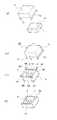
次に、この包装補助具400、透視カバー401及び戴置トレー409を使用した包装方法について図26〜図28について説明する。尚、包装用外箱には、図7、図8に示す包装用外箱13を使用し、同一符号を付して説明を省略する。  Next, a packaging method using thepackaging aid 400, theperspective cover 401, and the placingtray 409 will be described with reference to FIGS. In addition, the packagingouter box 13 shown in FIG. 7, FIG. 8 is used for a packaging outer box, the same code | symbol is attached | subjected and description is abbreviate | omitted.

まず、図26(a)に示すように抜け止部側の開口部を下に向けて戴置した包装補助具400に、抜け止部とは反対側の開口部より開口部を上に向けた状態で透視カバー401を挿入する。  First, as shown in FIG. 26 (a), the packagingauxiliary tool 400 placed with the opening on the retaining portion side facing down faces the opening upward from the opening on the side opposite to the retaining portion. In this state, thefluoroscopic cover 401 is inserted.

挿入された透視カバー401は、カバー天板412の縁部が抜け止部、即ち板材407及び支持片408に当接し、下側即ち抜け止部側の開口部より抜けないようになっている。また、包装補助具400の支持片408,408によりカバー天板412が支持される。  The insertedfluoroscopic cover 401 is configured such that the edge of the covertop plate 412 abuts against a retaining portion, that is, theplate member 407 and thesupport piece 408, and does not come out from the lower portion, that is, the opening on the retaining portion side. Further, the covertop plate 412 is supported by thesupport pieces 408 and 408 of the packagingauxiliary tool 400.

また、透視カバー401の係止用突片421は、包装補助具400の前側板402及び背側板403に形成された回避用切欠き407,407に逃げて邪魔にならないようになっている。  Further, the lockingprotrusion 421 of thefluoroscopic cover 401 escapes to theavoidance cutouts 407 and 407 formed on thefront side plate 402 and theback side plate 403 of the packagingauxiliary tool 400 so as not to get in the way.

この状態で、図26(b)に示すように、抜け止部とは反対側の開口部より巨峰等の収容物Aを包装補助具400内に挿入する。  In this state, as shown in FIG. 26 (b), a container A such as a giant peak is inserted into thepackaging aid 400 from the opening on the side opposite to the retaining portion.

このとき、収容物Aは、下部を透視カバー401に、上部を包装補助具400にそれぞれ囲まれている。  At this time, the container A is surrounded by thefluoroscopic cover 401 at the lower part and thepackaging aid 400 at the upper part.

次に、図26(c)〜図27(d)に示すように、戴置トレー409を戴置面を下に向けた状態で包装補助具400の開口部縁に被せ、係止片411を係止孔410に挿入させ係止させる。  Next, as shown in FIGS. 26 (c) to 27 (d), theloading tray 409 is placed on the edge of the opening of thepackaging aid 400 with the loading surface facing downward, and thelocking piece 411 is placed. It is inserted into thelocking hole 410 and locked.

そして、図27(e)〜図27(f)に示すように、左頂板51及び右頂板52を立ち上げた状態の包装用外箱13を戴置トレー409側から包装補助具400の外側に被せ、透視カバー401と収容物Aを内部に収容した包装補助具400及び戴置トレー409を包装用外箱13内に収容する。  Then, as shown in FIGS. 27 (e) to 27 (f), theouter packaging box 13 in a state where the lefttop plate 51 and the righttop plate 52 are raised is placed outside the packagingauxiliary tool 400 from the placingtray 409 side. Then, the packagingauxiliary tool 400 and the placingtray 409 in which thefluoroscopic cover 401 and the container A are accommodated are accommodated in the packagingouter box 13.

その状態で、図27(f)〜図28(g)に示すように、透視カバー401のカバー天板411を手で押さえながら包装用外箱13をひっくり返し、透視カバー401を上面側に露出させる。  In this state, as shown in FIGS. 27 (f) to 28 (g), the packagingouter box 13 is turned over while holding the covertop plate 411 of thefluoroscopic cover 401 by hand, and thefluoroscopic cover 401 is exposed to the upper surface side. Let

次に、図28(h)に示すように、包装補助具400を包装用外箱13内より上方に引き抜き、包装補助具400を取り除く。  Next, as shown in FIG. 28 (h), thepackaging aid 400 is pulled upward from the packagingouter box 13 to remove thepackaging aid 400.

このとき、戴置トレー409の係止孔410に係止されていた包装補助具400の係止片411は、収容物Aの重量によって戴置トレー409が包装用外箱13内に残ることによって外れるようになっている。  At this time, thelocking piece 411 of the packagingauxiliary tool 400 that has been locked in thelocking hole 410 of theloading tray 409 is caused by theloading tray 409 remaining in theouter packaging box 13 due to the weight of the contents A. It comes to come off.

また、透視トレー401は、引抜方向に係止されるものがないので包装用外箱13内に取り残される。  Further, since thefluoroscopic tray 401 is not locked in the drawing direction, it is left in theouter packaging box 13.

最後に、図28(i)に示すように、包装用外箱13の左頂板51及び右頂板52を折り目より折り曲げるとともに、係止片67を包装用外箱の前上縁板54及び背上縁板57の係止孔68に係合させることによって、透視カバー401を通して収容物Aを透視可能なように包装が完了する。  Finally, as shown in FIG. 28 (i), the lefttop plate 51 and the righttop plate 52 of the packagingouter box 13 are bent from the folds, and the lockingpieces 67 are connected to the frontupper edge plate 54 and the back of the packaging outer box. By engaging with the locking holes 68 of theedge plate 57, the packaging is completed so that the contents A can be seen through the see-throughcover 401.

本発明は、巨峰やさくらんぼう等の高級果物の他、菓子等の展示を行う収容物の包装にも適用することができる。  The present invention can be applied to packaging of items to be displayed such as confectionery as well as high-class fruits such as Kyoho and cherry.

本発明に係る包装用容器の実施の一例を示す斜視図である。It is a perspective view which shows an example of implementation of the packaging container which concerns on this invention.図1中の透視カバー及び戴置トレーを示す分解斜視図である。It is a disassembled perspective view which shows the see-through cover and loading tray in FIG.同上の透視カバーの展開図である。It is an expanded view of a see-through cover same as the above.同上の戴置トレーを示す部分拡大断面図である。It is a partial expanded sectional view which shows the loading tray same as the above.同上の戴置トレーの展開図である。It is an expanded view of the loading tray same as the above.同上の戴置トレーの他の実施形態を示す部分拡大断面図である。It is a partial expanded sectional view which shows other embodiment of the loading tray same as the above.同上の包装用外箱を示す斜視図である。It is a perspective view which shows the outer packaging box same as the above.同上の包装用外箱の展開図である。It is an expanded view of the outer packaging box same as the above.同上の包装用外箱の組立中間部材までの組立工程を示す斜視図である。It is a perspective view which shows the assembly process to the assembly intermediate member of the outer packaging box same as the above.同上の包装用外箱の製箱工程を示す斜視図である。It is a perspective view which shows the box making process of the packaging outer box same as the above.本発明に係る包装用容器を使用した包装工程の状態を示す斜視図である。It is a perspective view which shows the state of the packaging process using the packaging container which concerns on this invention.同上の包装工程の状態を示す斜視図である。It is a perspective view which shows the state of a packaging process same as the above.同上の包装工程の他の一例の状態を示す斜視図である。It is a perspective view which shows the state of another example of a packaging process same as the above.本発明に係る包装用容器の他の実施例を示す斜視図である。It is a perspective view which shows the other Example of the packaging container which concerns on this invention.図13中の透視カバーを示す斜視図である。It is a perspective view which shows the see-through cover in FIG.同上の包装用外箱を示す斜視図である。It is a perspective view which shows the outer packaging box same as the above.同上の包装用外箱の展開図である。It is an expanded view of the outer packaging box same as the above.同上の包装用外箱の中間組立工程の状態を示す斜視図である。It is a perspective view which shows the state of the intermediate | middle assembly process of the packaging outer box same as the above.同上の包装用外箱の組立工程の状態を示す斜視図である。It is a perspective view which shows the state of the assembly process of the outer packaging box same as the above.同上の包装用容器を使用した包装工程の状態を示す斜視図である。It is a perspective view which shows the state of the packaging process using the packaging container same as the above.同上の包装用容器を外カバーにより覆う場合を示す分解斜視図である。It is a disassembled perspective view which shows the case where the packaging container same as the above is covered with an outer cover.(a)は同上の透視カバーの他の一例を示す平面図、(b)は同断面図である。(A) is a top view which shows another example of a see-through cover same as the above, (b) is the sectional drawing.本発明方法に使用する包装補助具を示す斜視図である。It is a perspective view which shows the packaging assistance tool used for this invention method.同上の透視カバーの他の一例を示す斜視図である。It is a perspective view which shows another example of a see-through cover same as the above.同上の戴置トレーの他の一例を示す斜視図である。It is a perspective view which shows another example of the loading tray same as the above.本発明方法における包装工程の状態を示す斜視図である。It is a perspective view which shows the state of the packaging process in this invention method.同上の包装工程の状態を示す斜視図である。It is a perspective view which shows the state of a packaging process same as the above.同上の包装工程の状態を示す斜視図である。It is a perspective view which shows the state of a packaging process same as the above.従来の包装用箱を示す斜視図である。It is a perspective view which shows the conventional packaging box.

符号の説明Explanation of symbols

A 収容物(巨峰)
10 包装用容器
11 透視カバー
12 戴置トレー
13 包装用外箱
14 カバー天板
15〜18 折り目
19 カバー前側板
20 カバー背側板
21 カバー左側板
22 カバー右側板
23 通気孔
24 係止突片
25 切れ目
26 糊しろ
27 係止用孔
28 切れ目
28a 折り目
29 ラミネート層
30 緩衝材
30a 凹部
31 トレー底板
32 トレー前側板
33 トレー背側板
34 トレー左側板
35 トレー右側板
36 係止用突片
37 接着板
38 外箱底板
39〜42 折り目
43 外箱前側板
44 外箱背側板
45 外箱左側板
46 外箱右側板
47 前左側板間連結板
48 前右側板間連結板
49 背左側板間連結板
50 背右側板間連結板
51 左頂板
52 右頂板
53 前外側板
54 前上縁板
55 前内側板
56 背外側板
57 背上縁板
58 背内側板
59 折り目
60 逃がし片部
61 係止孔
62 下側係止突起
63 係止孔
64 側縁係止突起
65 指穴
66 切欠
67 係止片
68 係止孔
69 折り目
70 折り目
71 折り目
72 固定部
73 可動部
80 組立中間部材
110 包装用容器
111 透視カバー
112 包装用外箱
113 カバー天板
114〜117 折り目
118 カバー前側板
119 カバー背側板
120 カバー左側板
121 カバー右側板
122 通気孔
123 係止突片
124 切れ目
125 糊しろ
126 外箱底板
127〜130 折り目
131 外箱前側板
132 外箱背側板
133 外箱左側板
134 外箱右側板
135 前左側板間連結板
136 前右側板間連結板
137 背左側板間連結板
138 背右側板間連結板
139 前外側板
140 前上縁板
141 前内側板
142 接着片
143 背外側板
144 背上縁板
145 背内側板
146 接着片
147 切れ目
148、149 折り目
150 折り目
151 逃がし片部
152 係止凹部
153 側縁係止突起
154 指穴
155 折り目
156 補強板
157 左外側板
158 左上縁板
159 左内側板
160 折り目
161 補強片
162 右上縁板
163 差込板
164 係止凹部
165 係止突起
166 折り目
167 固定部
168 可動部
169 折り目
170 組立中間部材
200 外カバー
201 係止孔
202 係止片
300 凹部
400 包装補助具
401 透視カバー
402 前側板
403 背側版
404 左側板
405 右側板
406 板材
407 回避用切欠き
408 支持片
409 戴置トレー
410 係止孔
411 係止片
412 カバー天板
413〜416 折り目
417 カバー前側板
418 カバー背側板
419 カバー左側板
420 カバー右側板
421 係止突片
422 糊代
A Containment (Kyoho)
DESCRIPTION OF SYMBOLS 10 Packaging container 11 Perspective cover 12 Placement tray 13 Packaging outer box 14 Cover top plate 15-18 Fold 19 Cover front plate 20 Cover back plate 21 Cover left plate 22 Cover right plate 23 Venting hole 24 Locking protrusion 25 Cut 26 Margin 27 Lock hole 28 Cut 28a Fold 29 Laminate layer 30 Buffer 30a Recess 31 Tray bottom plate 32 Tray front plate 33 Tray back plate 34 Tray left plate 35 Tray right plate 36 Locking protrusion 37 Adhesive plate 38 Outside Box bottom plate 39-42 Crease 43 Outer box front side plate 44 Outer box back side plate 45 Outer box left side plate 46 Outer box right side plate 47 Front left side plate connecting plate 48 Front right side plate connecting plate 49 Back left side plate connecting plate 50 Back right side Inter-plate connecting plate 51 Left top plate 52 Right top plate 53 Front outer plate 54 Front upper edge plate 55 Front inner plate 56 Back outer plate 57 Back upper edge plate 58 Back Inner Plate 59 Fold 60 Relief Piece 61 Locking Hole 62 Lower Locking Projection 63 Locking Hole 64 Side Edge Locking Projection 65 Finger Hole 66 Notch 67 Locking Piece 68 Locking Hole 69 Fold 70 Fold 71 Fold 71 Fixed part 73 Movable part 80 Assembly intermediate member 110 Packaging container 111 Transparent cover 112 Packaging outer box 113 Cover top plate 114-117 Crease 118 Cover front side plate 119 Cover back side plate 120 Cover left side plate 121 Cover right side plate 122 Vent hole 123 Engagement Stopping piece 124 Cut 125 Gluing 126 Outer box bottom plate 127-130 Fold 131 Outer box front side plate 132 Outer box back side plate 133 Outer box left side plate 134 Outer box right side plate 135 Front left side plate connecting plate 136 Front right side plate connecting plate 137 Back left side plate connecting plate 138 Back right side plate connecting plate 139 Front outer side plate 140 Front upper edge plate 41 Front inner side plate 142 Adhesive piece 143 Back outer side plate 144 Back upper edge plate 145 Back inner side plate 146 Adhesive piece 147 Cut 148, 149 Fold 150 Fold 151 Relief piece 152 Locking concave part 153 Side edge locking protrusion 154 Finger hole 155 Fold 156 Reinforcement plate 157 Left outer side plate 158 Left upper edge plate 159 Left inner side plate 160 Fold 161 161 Reinforcement piece 162 Upper right edge plate 163 Insertion plate 164 Locking recess 165 Locking protrusion 166 Fold 167 Fixed part 168 Movable part 169 Fold 170 Assembly intermediate member DESCRIPTION OF SYMBOLS 200 Outer cover 201 Locking hole 202 Locking piece 300 Recessed part 400 Packaging aid 401 Transparent cover 402 Front side plate 403 Back side plate 404 Left side plate 405 Right side plate 406 Plate material 407 Avoidance notch 408 Supporting piece 409 Loading tray 410 Locking Hole 411 Locking piece 412 Bar top plate 413 to 416 fold 417 cover the front plate 418 covers the back side plate 419 covering the left side plate 420 covering the right side plate 421 engaging protrusion 422 overlap

Claims (13)

Translated fromJapanese
平板状のカバー天板と、該カバー天板の周縁に折り目を介して一体に形成されたカバー前側板、カバー背側板、カバー左側板及びカバー右側板とを有する下面が開口した箱状に形成された透明な透視カバーと、
平板状の外箱底板と、該外箱底板の周縁より立ち上げた外箱前側板、外箱背側板、外箱左側板及び外箱右側板とを有し、前記透視カバーが開口部を下にして内部に嵌まり込む包装用外箱とを備え、
前記透視カバーを通して収容物を透視可能なように収容することを特徴としてなる包装用容器。
Formed in a box shape with a flat bottom cover top plate and a lower surface having a cover front side plate, a cover back side plate, a cover left side plate and a cover right side plate integrally formed through a crease at the periphery of the cover top plate A transparent see-through cover,
A flat outer box bottom plate, an outer box front side plate, an outer case back side plate, an outer case left side plate, and an outer case right side plate raised from the periphery of the outer case bottom plate, and the see-through cover has a lower opening. And a packaging outer box that fits inside,
A packaging container that accommodates an item so as to be seen through the see-through cover.
透視カバーは、対向するカバー左側板及びカバー右側板をそれぞれ開口部側が広く形成された台形状とし、包装用外箱は、対向する外箱左側板及び外箱右側板をそれぞれ底板側が広く形成された台形状とした請求項1に記載の包装用容器。  The see-through cover has a trapezoidal shape in which the opposing cover left side plate and the cover right side plate are each formed wide on the opening side, and the packaging outer box is formed so that the opposing outer box left side plate and the outer box right side plate are each wide on the bottom plate side. The packaging container according to claim 1, which has a trapezoidal shape. 包装用外箱は、外箱左側板又は外箱右側板の一方を開閉可能とした請求項1又は2に記載の包装用容器。  The packaging container according to claim 1 or 2, wherein the packaging outer box is capable of opening and closing one of the outer box left side plate and the outer box right side plate. 透視カバーは、カバー天板の周縁に係止用突片を備えた請求項1、2又は3に記載の包装用容器。  The packaging container according to claim 1, wherein the see-through cover is provided with a locking protrusion on the periphery of the cover top plate. 透視カバーの開口部縁に着脱自在に嵌まり込む戴置トレーを備えた請求項1〜3又は4に記載の包装用容器。  The packaging container according to claim 1, further comprising a placing tray that is detachably fitted into an opening edge of the fluoroscopic cover. 戴置トレーは、その上面側に収容物の形状に合わせて形成された凹部を有する緩衝材を備えた請求項5に記載の包装用容器。  The packaging container according to claim 5, wherein the loading tray includes a cushioning material having a concave portion formed in accordance with the shape of the stored item on the upper surface side thereof. 戴置トレーは、上面にラミネート層を介して緩衝材を重ね合わせた請求項5または6に記載の包装用容器。  The packaging container according to claim 5 or 6, wherein the placing tray has a cushioning material superimposed on an upper surface through a laminate layer. 戴置トレーは、その前背縁部より突出し、透視カバーのカバー前側板及びカバー背側板の下端部に形成された係止用孔に挿入されて係止される係止用突片を備えた請求項5、6又は7に記載の包装用容器。  The loading tray is provided with locking protrusions that protrude from the front back edge portion and are inserted into locking holes formed in the cover front side plate of the fluoroscopic cover and the lower end portion of the cover back side plate and locked. The packaging container according to claim 5, 6 or 7. 係止用孔は、その両側縁に左右方向に向けた切れ目を備えた請求項8に記載の包装用容器。  The packaging container according to claim 8, wherein the locking hole is provided with cuts directed in the left-right direction on both side edges. 透視カバーは、係止用孔の両端部よりカバー天板とは反対側の縁部に向けて斜め方向に折り目を備えた請求項8又は9に記載の包装用容器。  The packaging container according to claim 8 or 9, wherein the fluoroscopic cover is provided with a fold in an oblique direction from both ends of the locking hole toward an edge on the side opposite to the cover top plate. 透視カバーは、カバー天板に表面側に凹んだ複数の凹部を備えた請求項1〜10に記載の包装用容器。  The packaging container according to claim 1, wherein the see-through cover includes a plurality of recesses recessed on the surface side of the cover top plate. 前側板、背側板、左側板及び右側板からなる角筒状に形成され、その一方の開口部内縁に突出した抜け止部を備えた包装補助具を使用し、
該包装補助具内に、平板状のカバー天板と、該カバー天板の周縁に折り目を介して一体に形成されたカバー前側板、カバー背側板、カバー左側板及びカバー右側板とを有する下面が開口した箱状に形成された透明な透視カバーを挿入し、前記カバー天板を前記抜け止部に係止させた状態で、前記抜け止部とは反対側の開口部より前記包装補助具内に収容物を挿入し、
平板状の外箱底板と、該外箱底板の周縁より立ち上げた外箱前側板、外箱背側板、外箱左側板及び外箱右側板とを有する包装用外箱を前記透視カバー及び収容物が収容された前記包装補助具に被せた後、包装補助具を上方に引き抜くことにより収容物を透視カバーを介して透視可能に収容することを特徴とする包装方法。
Using a packaging aid that is formed in a rectangular tube shape consisting of a front side plate, a back side plate, a left side plate, and a right side plate, and that has a retaining portion protruding on the inner edge of one opening thereof,
A lower surface having a flat cover top plate and a cover front side plate, a cover back side plate, a cover left side plate, and a cover right side plate integrally formed through a crease at the periphery of the cover top plate in the packaging aid. Inserting a transparent see-through cover formed in a box shape with an opening, and holding the cover top plate to the retaining portion, the packaging aid from the opening on the opposite side of the retaining portion Insert the contents into the inside,
A packaging outer box having a flat outer box bottom plate and an outer box front side plate, an outer box back side plate, an outer box left side plate, and an outer box right side plate raised from the peripheral edge of the outer box bottom plate, and the transparent cover and housing A packaging method characterized in that, after covering a packaging aid containing an article, the packaging aid is pulled out upward to accommodate the accommodation through the fluoroscopic cover.
包装補助具の抜け止部とは反対側の開口部に着脱自在に取り付けられる戴置トレーを備えた請求項12に記載の包装方法。  The packaging method according to claim 12, further comprising a placing tray that is detachably attached to the opening on the side opposite to the retaining portion of the packaging aid.
JP2003387364A2003-11-182003-11-18Packaging container and packaging methodPendingJP2005145523A (en)

Priority Applications (1)

Application NumberPriority DateFiling DateTitle
JP2003387364AJP2005145523A (en)2003-11-182003-11-18Packaging container and packaging method

Applications Claiming Priority (1)

Application NumberPriority DateFiling DateTitle
JP2003387364AJP2005145523A (en)2003-11-182003-11-18Packaging container and packaging method

Publications (1)

Publication NumberPublication Date
JP2005145523Atrue JP2005145523A (en)2005-06-09

Family

ID=34694730

Family Applications (1)

Application NumberTitlePriority DateFiling Date
JP2003387364APendingJP2005145523A (en)2003-11-182003-11-18Packaging container and packaging method

Country Status (1)

CountryLink
JP (1)JP2005145523A (en)

Cited By (4)

* Cited by examiner, † Cited by third party
Publication numberPriority datePublication dateAssigneeTitle
PL126519U1 (en)*2017-08-032019-02-11Prokopek Jan Przed Produkcyjno Uslugowo Handlowe ProjanOpen package
JP2019218101A (en)*2018-06-202019-12-26三菱重工サーマルシステムズ株式会社Packaging container and sheet member for packaging container
DE202019100800U1 (en)*2019-02-122020-05-15Gissler & Pass Gmbh Packaging container
NO20200844A1 (en)*2020-07-172022-01-18Bama Packaging AsA packaging box for grapes and other fragile fruits and vegetables, and a method for using it

Cited By (5)

* Cited by examiner, † Cited by third party
Publication numberPriority datePublication dateAssigneeTitle
PL126519U1 (en)*2017-08-032019-02-11Prokopek Jan Przed Produkcyjno Uslugowo Handlowe ProjanOpen package
JP2019218101A (en)*2018-06-202019-12-26三菱重工サーマルシステムズ株式会社Packaging container and sheet member for packaging container
JP7182909B2 (en)2018-06-202022-12-05三菱重工サーマルシステムズ株式会社 Packing containers and sheet materials for packing containers
DE202019100800U1 (en)*2019-02-122020-05-15Gissler & Pass Gmbh Packaging container
NO20200844A1 (en)*2020-07-172022-01-18Bama Packaging AsA packaging box for grapes and other fragile fruits and vegetables, and a method for using it

Similar Documents

PublicationPublication DateTitle
US10442597B1 (en)Retention package with article-loading aperture and method of making and using the same
KR20180087242A (en) Pack for consumer goods
JP4199043B2 (en) Footwear storage box for moving
WO2009136377A1 (en)Container for carrying hot pizzas and the like
JP2005145523A (en)Packaging container and packaging method
JP6909042B2 (en) Packaging box and manufacturing method of packaging box
US20030066773A1 (en)Packaging container for containing plural rolls of strip material
JP2005280774A (en)Packaging container
JP2007106467A (en)Air packing device
JP3160659U (en) Assembly packaging box with integrated lid
KR200457917Y1 (en) Packing box
JP2005280824A (en)Assembly type box
JP6507766B2 (en) Packaging box
US20200140137A1 (en)Tracking device enclosure
CZ28287U1 (en)Sales package and sales wrapper
JP2006001572A (en)Packaging method
JP6626019B2 (en) Packaging containers and blanks
JP2013159369A (en)Packing and packaging device for three-dimensional object
JP2002053127A (en)Tray box with locked lid
JP3490556B2 (en) Storage box
JP2011173634A (en)Packaging box
JP2005145524A (en)Assembly box
JPH09132284A (en) Kitchen knife packaging
JP3757257B2 (en) Container with vial stand and ampoule storage
JP2006182428A (en) Food packaging container

Legal Events

DateCodeTitleDescription
A977Report on retrieval

Free format text:JAPANESE INTERMEDIATE CODE: A971007

Effective date:20070530

A131Notification of reasons for refusal

Free format text:JAPANESE INTERMEDIATE CODE: A131

Effective date:20070904

A02Decision of refusal

Free format text:JAPANESE INTERMEDIATE CODE: A02

Effective date:20080108


[8]ページ先頭

©2009-2025 Movatter.jp