JP2005144564A - Portable electric tool - Google Patents
Portable electric toolDownload PDFInfo
- Publication number
- JP2005144564A JP2005144564AJP2003381458AJP2003381458AJP2005144564AJP 2005144564 AJP2005144564 AJP 2005144564AJP 2003381458 AJP2003381458 AJP 2003381458AJP 2003381458 AJP2003381458 AJP 2003381458AJP 2005144564 AJP2005144564 AJP 2005144564A
- Authority
- JP
- Japan
- Prior art keywords
- battery pack
- grip
- portable electric
- electric tool
- mode switching
- Prior art date
- Legal status (The legal status is an assumption and is not a legal conclusion. Google has not performed a legal analysis and makes no representation as to the accuracy of the status listed.)
- Pending
Links
Images


Classifications
- B—PERFORMING OPERATIONS; TRANSPORTING
- B25—HAND TOOLS; PORTABLE POWER-DRIVEN TOOLS; MANIPULATORS
- B25B—TOOLS OR BENCH DEVICES NOT OTHERWISE PROVIDED FOR, FOR FASTENING, CONNECTING, DISENGAGING OR HOLDING
- B25B21/00—Portable power-driven screw or nut setting or loosening tools; Attachments for drilling apparatus serving the same purpose
- B—PERFORMING OPERATIONS; TRANSPORTING
- B25—HAND TOOLS; PORTABLE POWER-DRIVEN TOOLS; MANIPULATORS
- B25F—COMBINATION OR MULTI-PURPOSE TOOLS NOT OTHERWISE PROVIDED FOR; DETAILS OR COMPONENTS OF PORTABLE POWER-DRIVEN TOOLS NOT PARTICULARLY RELATED TO THE OPERATIONS PERFORMED AND NOT OTHERWISE PROVIDED FOR
- B25F5/00—Details or components of portable power-driven tools not particularly related to the operations performed and not otherwise provided for
- B25F5/02—Construction of casings, bodies or handles
Landscapes
- Engineering & Computer Science (AREA)
- Mechanical Engineering (AREA)
- Portable Power Tools In General (AREA)
- Details Of Spanners, Wrenches, And Screw Drivers And Accessories (AREA)
- Scissors And Nippers (AREA)
- Drilling And Boring (AREA)
Abstract
Description
Translated fromJapanese本発明は、ボルト、ナット、あるいは木ねじ等の締め付け作業、及び金工、木工、モルタル、コンクリート等の穴あけ作業、金工、木工等の切断作業に使用する可搬式(手持ち式)電動工具に関するものである。 The present invention relates to a portable (hand-held) electric tool used for tightening bolts, nuts, wood screws, etc., drilling work for metalwork, woodwork, mortar, concrete, etc., cutting work for metalwork, woodwork, etc. .
従来、可搬式電動工具は、手で把持するためのグリップ部の一端部に該グリップ部よりも外形が大きいシリンダー部を交差して設けると共にグリップ部の上記シリンダー部と反対側の端部に電池パック取付け部を設け、この電池パック取付け部にグリップ部よりも外形が大きい電池パックが着脱自在に取付けて構成してある。 2. Description of the Related Art Conventionally, a portable electric tool has a cylinder portion having an outer shape larger than that of a grip portion provided at one end portion of a grip portion for gripping by hand and a battery at an end portion of the grip portion opposite to the cylinder portion. A pack attachment portion is provided, and a battery pack having an outer shape larger than the grip portion is detachably attached to the battery pack attachment portion.
このような可搬式電動工具において、該電動工具の動作モード(例えば複数のトルクモード)を切り替えるためのモード切り替え操作部11’は、例えば、図9に示すようにシリンダー部8の外周面の電池パック6と反対側の面(つまり電池パック6を下とした場合にシリンダー部8の外周面の上面部分)に設けてあったり、あるいは図示を省略しているが、シリンダー部8の外周面に環状をしたモード切り替え操作部11’を設けてあった。 In such a portable power tool, the mode
ところが、上記のような従来の可搬式電動工具は、作業者の不注意から可搬式電動工具が落下したり、転倒したりするおそれがある。このように、可搬式電動工具が落下したり、転倒したりした場合、グリップ部7の両側にグリップ部7よりも外形が大きいシリンダー部8と電池パック6とが存在するという可搬式電池工具の形状的な特性のため、グリップ部7の両端部のシリンダー部8側と電池パック6側とが共に同一平面に当接する全ての場合における両側の当接部分を結ぶ線で囲まれた領域よりも外側の部分、すなわち、可搬式電動工具を電池パック6側が下、シリンダー部8側が上と定義した場合、シリンダー部8の外周の上面や左右の側面、電池パック6の下面や前後、左右の側面が地面や床に衝突する。このため、上記のようにシリンダー部8の上面に動作モードを切り替えるためのモード切り替え操作部11’を設けたり、あるいは円筒シリンダーの外周面に環状の動作モードを切り替えるためのモード切り替え操作部を設ける従来例においては、動作モード切り替えのためのモード切り替え操作部が破損しやすいという問題がある。 However, the conventional portable electric tool as described above may fall or fall over due to carelessness of the operator. Thus, when a portable electric tool falls or falls, the portable battery tool of the
また、可搬式電動工具において、電池パックの後側面部の左右幅を狭くしてこの幅狭の後側面部に電池パックのにバッテリーの容量表示部を設けたものが特許文献1により知られている。 Further, in a portable power tool, Patent Document 1 discloses that a left and right width of a rear side surface portion of a battery pack is narrowed and a battery capacity display portion is provided on the rear side surface portion of the narrow battery pack. Yes.
このものは可搬式電動工具が左右方向に倒れた時には上記のように容量表示部を設けた電池パックの後側面部の左右幅を幅狭としてあることで、容量表示部が地面や床に衝突することはないが、可搬式電動工具が後方に倒れた場合、電池パックの後側面に設けた容量表示部が直接地面や床に衝突し、破損するおそれがある。
本発明は上記の従来の問題点に鑑みて発明したものであって、落下や転倒しても床や地面にモード切り替え操作部が直接衝突して損傷することがない可搬式電動工具を提供することを課題とするものである。 The present invention has been invented in view of the above-described conventional problems, and provides a portable electric tool in which a mode switching operation unit does not directly collide with a floor or the ground even if it falls or falls and is damaged. Is an issue.
上記課題を解決するために本発明に係る可搬式電動工具は、モータ1の回転を減速伝達する駆動部2と、駆動部2の回転出力を出力する出力軸3と、モータ1の回転を指示するスイッチ部4と、該モータ1、駆動部2、出力軸3、スイッチ部4を覆うハウジング5と、該ハウジング5に着脱自在な電池パック6とを備え、該ハウジング5は、手で把持するためのグリップ部7の一端部に該グリップ部7よりも外形が大きいシリンダー部8を交差して設けると共にグリップ部7の上記シリンダー部8と反対側の端部に電池パック取付け部9を設けて構成され、該ハウジング5の電池パック取付け部9にグリップ部7よりも外形が大きい電池パック6が着脱自在に取付けられる可搬式電動工具10において、該工具10にモード切り替え操作部11を設け、該モード切り替え操作部11を、グリップ部7の両端部のシリンダー部8側と電池パック6側とが共に同一平面に当接する全ての場合における両側の当接部分を結ぶ線で囲まれた領域よりも内側に配置して成ることを特徴とするものである。 In order to solve the above-described problems, a portable electric tool according to the present invention includes a
このような構成とすることで、工具10が落下したり、転倒したりしてもモード切り替え操作部11が直接地面や床15に衝突して破損することがないものである。 With such a configuration, even if the
また、工具10に制御回路13の監視を行う内容を表示する表示部12を備え、該表示部12を、グリップ部7の両端部のシリンダー部8側と電池パック6側とが共に同一平面に当接する全ての場合における両側の当接部分を結ぶ線よりも内側の領域に配置することが好ましい。 Further, the
このような構成とすることで、工具10が落下したり、転倒したりしても表示部12が直接地面や床15に衝突して破損することがないものである。 With such a configuration, even if the
また、表示部12が液晶表示であることが好ましい。 The
このような構成とすることで、工具10が落下したり、転倒したりしても破損しやすい液晶表示の保護ができる
また、電池パック取付け部9のグリップ部7側を向いた面にモード切り替え操作部11を設けることが好ましい。With this configuration, it is possible to protect a liquid crystal display that is easily damaged even if the
このような構成とすることで、グリップ部7の端部の電池パック取付け部9を有効に利用して工具10が落下したり、転倒したりしてもモード切り替え操作部11が直接地面や床15に衝突して破損することがないようにでき、また、グリップ部7を手で掴むに当たって、モード切り替え操作部11が邪魔にならないものである。 With such a configuration, even if the
また、モード切り替え操作部11を、上記グリップ部7の両端部のシリンダー部8側と電池パック6側とが共に同一平面に当接する全ての場合における両側の当接部分を結ぶ線よりも内側の領域で且つグリップ部7の外面よりも外方側にずらしたグリップ部7以外の部位に配置することが好ましい。 In addition, the mode
このような構成とすることで、上記のように工具10が落下したり、転倒したりした場合にモード切り替え操作部11が直接地面や床に衝突しないように、モード切り替え操作部11を、グリップ部7の両端部のシリンダー部8側と電池パック6側とが共に同一平面に当接する全ての場合における両側の当接部分を結ぶ線で囲まれた領域よりも内側に配置したものにおいて、グリップ部7を手で掴んだ状態で、グリップ部7の外面よりも外方側にずらしたグリップ部7以外の部位に配置したモード切り替え操作部11の状態を確認したり、あるいは操作したりすることができるものである。 By adopting such a configuration, the mode
本発明は、工具が落下したり、転倒したりしてもモード切り替え操作部が直接地面や床に衝突して破損することがなく、長期間安定して使用でき、また、モード切り替え操作部の破損防止のための強度確保が容易に行えてコストダウンを図ることができるものである。 The present invention can be used stably for a long time without causing the mode switching operation unit to directly collide with the ground or the floor even if the tool falls or falls, and the mode switching operation unit can be used stably. The strength can be easily secured to prevent breakage and the cost can be reduced.
以下、本発明を添付図面に示す実施形態に基いて説明する。 Hereinafter, the present invention will be described based on embodiments shown in the accompanying drawings.
可搬式電動工具10(以下単に工具10という)は、インパクト工具、電動ドリルドライバー等であり、モータ1の回転を減速伝達する駆動部2と、駆動部2の回転出力を出力する出力軸3と、モータ1の回転を指示するスイッチ4を覆うハウジング5に電池パック6を着脱自在に取付けて構成してある。なお、添付図面に示す実施形態では工具10としてインパクト工具を例示している。 The portable electric tool 10 (hereinafter simply referred to as the tool 10) is an impact tool, an electric drill driver, or the like, and includes a
ハウジング5は、手で把持するためのグリップ部7の一端部(上端部)にシリンダー部8を交差して設けると共に、グリップ部7の上記シリンダー部8と反対側の端部である他端部(下端部)に電池パック取付け部9を設けて構成してあり、このハウジング5のグリップ部7の他端部に設けた電池パック取付け部9に電池パック6を電池パック6に設けた着脱操作部25の操作により離脱、及び、押し込みにより装着ができるように着脱自在に取付けある。シリンダー部8は円筒形状又は非円形筒状をしており、このシリンダー部8内には図2に示すようにモータ1、駆動部2、出力軸3の一部分が内装してあり、グリップ部7内にスイッチ4、トリガー16の一部分が内装してある。 The
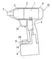
ここで、図1のように、電池パック6が下、シリンダー部8が上となるように工具10を配置した場合に図1のz方向を上下方向、シリンダー部8の軸方向(上記z方向と直交又は略直交する)である図1のx方向を前後方向、上記x方向、y方向のいずれにも略直交する方向である図1のy方向を左右方向と定義した場合、シリンダー部8はグリップ部7よりもシリンダー部8の軸方向である前後方向(x方向)の長さが長く、また、左右方向(y方向)の長さが長いものである。つまり、グリップ部7の一端部にグリップ部7と交差するように設けられたシリンダー部8の前後方向、左右方向における外形がグリップ部7の前後方向、左右方向における外形よりも大きくなっており、また、グリップ部7の左右両面はシリンダー部8の左右両面よりも内側に位置し且つグリップ部7の前後両面はシリンダー部8の左右両面よりも内側に位置している。 Here, as shown in FIG. 1, when the
また、グリップ部7の他端部に設けた電池パック取付け部9の前後方向の長さ、左右方向の長さはそれぞれグリップ部7の前後方向の長さ、左右方向の長さよりも長くなっていて電池パック取付け部9の前後方向、左右方向における外形がグリップ部7の前後方向、左右方向における外形よりも大きくなっており、また、グリップ部7の前後両面は電池パック取付け部9の前後両面と略同じか又は内側に位置し、グリップ部7の左右両面は電池パック取付け部9の左右両面と略同じか又は内側に位置している。 In addition, the length in the front-rear direction and the length in the left-right direction of the battery
更に、電池パック6の前後方向の長さ、左右方向の長さはそれぞれグリップ部7の前後方向の長さ、左右方向の長さよりも長くなっていて電池パック6の前後方向、左右方向における外形もグリップ部7の前後方向、左右方向における外形よりも大きくなっており、また、グリップ部7の前後両面は電池パック6の前後両面と略同じか又は内側に位置し、グリップ部7の左右両面は電池パック6の左右両面と略同じか内側に位置している。 Further, the length of the
そして、添付図面に示す実施形態では電池パック取付け部9の前後方向、左右方向における外形と、電池パック6の前後方向、左右方向における外形とは略同じとなっている。 In the embodiment shown in the accompanying drawings, the outer shape of the battery
上記のような工具10において、本発明は、該工具10にモード切り替え操作部11を設け、該モード切り替え操作部11を、グリップ部7の両端部のシリンダー部8側と電池パック6側とが共に同一平面に当接する全ての場合における両側の当接部分を結ぶ線で囲まれた領域よりも内側に配置したことに特徴がある。 In the
すなわち、図1、図2、図3に示す実施形態においては、電池パック取付け部9の前部がグリップ部7の前面よりも前方に突出した前方突出部24となっており、この前方突出部24の上面部に可搬式電動工具10のモード切り替え操作部11と、工具10に制御回路13の監視を行う内容を表示する表示パネルよりなる表示部12とが設けてある。 That is, in the embodiment shown in FIGS. 1, 2, and 3, the front portion of the battery
ここで、工具10を倒した場合、グリップ部7よりもシリンダー部8、電池パック6の外形が大きいため、グリップ部7の両端部のシリンダー部8側と電池パック6側とが共に同一平面(地面又は床15)に当接し、グリップ部7は地面又は床15から浮くことになる。工具10を倒して地面又は床15に共に当接するのは、図5のように、工具10の前側が下となるように倒した場合(この場合にはシリンダー部8の前端又は出力軸3の前端と、電池パック6の前面とが地面又は床15に当たる)、図6のように、工具10の後側が下となるように倒した場合(この場合にはシリンダー部8の後端面と、電池パック6の後面とが地面又は床15に当たる)、図7のように、工具10が左側又は右側に倒れた場合(この場合にはシリンダー部8の左右いずれかの側面と、電池パック6の左右いずれかの側面とが地面又は床15に当たる)がある。このいずれの場合も、電池パック取付け部9の前方突出部24のモード切り替え操作部11と表示部12とを設けた部分は地面又は床15から浮いている。つまり、モード切り替え操作部11と表示部12は、グリップ部7の両端部のシリンダー部8側と電池パック6側とが共に同一平面(地面又は床15)に当接する全ての場合における両側の当接部分を結ぶ線で囲まれた領域よりも内側に配置していることになり、したがって、工具10を落下又は転倒させた場合に、直接モード切り替え操作部11、表示部12が地面又は床15に当接せず、モード切り替え操作部11、表示部12が破損しないようになっている。 Here, when the
モード切り替え操作部11としては、例えばトルク切り替えスイッチ11aや増し締め設定スイッチ11b等がある。図4には本発明の一例の制御ブロック図が示してあり、13は制御回路13であり、トルク切り替えスイッチ11aや増し締め設定スイッチ11b等のモード切り替え操作部11を操作してモード切り替えを行うと、該モード切り替え信号が制御回路13に入力され、設定された動作モードとなるように制御回路13からメインスイッチ20、スイッチング素子21、正逆切り替えスイッチ22を備えたスイッチ部4に制御信号を出力してモータ1を制御するようになっている。この場合、打撃検知回路17で打撃(本実施形態ではインパクト回転工具の例が示してあるのでインパクト回転工具に設けたアンビルの打撃)を検知し、トルク算出回路18でトルクを算出し、回転センサ19でモータ1の回転を検知してこれら打撃検知回路17、トルク算出回路18、回転センサ19での検出情報が制御回路13に入力されてこの検出情報に基いてモード切り替え操作部11で切り替え設定された目的の動作モードに制御回路13により制御されるものである。これによりトルク切り替えスイッチ11aを操作することで複数の異なるトルクモードのうちいずれかのトルクモードに選択的に切り替えたり、あるいは、増し締め設定スイッチ11bを操作することで増し締めモード又は増し締め解除モード等を切り替えることができるようにしてある。これらのモード切り替え操作部11を操作して切り替えられた動作モードは表示部12に表示される。なお、図4において23は電池パック6に内蔵された2次電池である。 Examples of the mode
添付図面に示す実施形態では、図2、図3に示すように電池パック取付け部9内に内装した制御回路13を備えた制御回路モジュール14が内装してあり、この電池パック取付け部9内に内装した制御回路モジュール14に電池パック取付け部9の前方突出部24の上面に設けた表示部12を構成する表示パネル、モード切り替え操作部11が配線接続してある。 In the embodiment shown in the accompanying drawings, as shown in FIGS. 2 and 3, a
表示部12を構成する表示パネルは例えば液晶表示モジュールであり、上記制御回路モジュール14とは別体であるが、制御回路モジュール14のプリント基板上に直接設けてもよい。また、制御回路モジュール14上にLEDなどを配置して表示パネルに透過表示させるようにしてもよい。 The display panel constituting the
上記のように、グリップ部7の一端部に設けたシリンダー部8内にモータ1、駆動部2を内装し、グリップ部7の他端部に設けた電池パック取付け部9に表示部12を設け、更に該電池パック取付け部9内に制御回路モジュール14を内装することで、モータ1、駆動部2からより遠い位置に表示部12、制御回路モジュール14を配置でき、これによりモータ1、駆動部2で発生する振動を緩和できて、表示部12(特に表示部12を液晶で構成した場合における液晶表示パネル)及び制御回路モジュール14の強度確保が容易に行え、コストダウンを図ることができるものである。 As described above, the motor 1 and the
図7にはモード切り替え操作部11と表示部12とを別々に設けた例を示しているが、図8のように、表示部12を構成する表示パネルの一部にモード切り替え操作部11を設け、制御回路モジュール14にスイッチング部を設け、表示部12の一部に設けたモード切り替え操作部11によりスイッチング部を操作するようにしてもよい。 FIG. 7 shows an example in which the mode
1 モータ
2 駆動部
3 出力軸
4 スイッチ部
5 ハウジング
6 電池パック
7 グリップ部
8 シリンダー部
9 電池パック取付け部
10 工具
11 モード切り替え操作部
12 表示部
13 制御回路
DESCRIPTION OF SYMBOLS 1
Claims (5)
Translated fromJapanesePriority Applications (6)
| Application Number | Priority Date | Filing Date | Title |
|---|---|---|---|
| JP2003381458AJP2005144564A (en) | 2003-11-11 | 2003-11-11 | Portable electric tool |
| EP04256956AEP1533086B1 (en) | 2003-11-11 | 2004-11-10 | Electroportable tool with protected operation members |
| US10/984,971US20050121209A1 (en) | 2003-11-11 | 2004-11-10 | Transportable power tool |
| DE602004011304TDE602004011304T2 (en) | 2003-11-11 | 2004-11-10 | Electric hand tool with more protected actuators |
| AT04256956TATE383928T1 (en) | 2003-11-11 | 2004-11-10 | HAND ELECTRIC TOOL WITH MORE PROTECTED ACTUATING ELEMENTS |
| CNB200410094640XACN100379528C (en) | 2003-11-11 | 2004-11-11 | Portable Power Tools |
Applications Claiming Priority (1)
| Application Number | Priority Date | Filing Date | Title |
|---|---|---|---|
| JP2003381458AJP2005144564A (en) | 2003-11-11 | 2003-11-11 | Portable electric tool |
Publications (1)
| Publication Number | Publication Date |
|---|---|
| JP2005144564Atrue JP2005144564A (en) | 2005-06-09 |
Family
ID=34431423
Family Applications (1)
| Application Number | Title | Priority Date | Filing Date |
|---|---|---|---|
| JP2003381458APendingJP2005144564A (en) | 2003-11-11 | 2003-11-11 | Portable electric tool |
Country Status (6)
| Country | Link |
|---|---|
| US (1) | US20050121209A1 (en) |
| EP (1) | EP1533086B1 (en) |
| JP (1) | JP2005144564A (en) |
| CN (1) | CN100379528C (en) |
| AT (1) | ATE383928T1 (en) |
| DE (1) | DE602004011304T2 (en) |
Cited By (16)
| Publication number | Priority date | Publication date | Assignee | Title |
|---|---|---|---|---|
| JP2005297121A (en)* | 2004-04-09 | 2005-10-27 | Hitachi Koki Co Ltd | Electric tool |
| JP2008062346A (en)* | 2006-09-07 | 2008-03-21 | Hitachi Koki Co Ltd | Electric tool |
| JP2008155353A (en)* | 2006-12-26 | 2008-07-10 | Makita Corp | Hammer drill |
| JP2008279564A (en)* | 2007-05-11 | 2008-11-20 | Hitachi Koki Co Ltd | Electric tool |
| JP2009072892A (en)* | 2007-09-24 | 2009-04-09 | Hitachi Koki Co Ltd | Electric tool |
| JP2009190131A (en)* | 2008-02-15 | 2009-08-27 | Makita Corp | Electric tool |
| US7673701B2 (en) | 2006-08-31 | 2010-03-09 | Matsushita Electric Works, Ltd. | Power tool having control means for monitoring screw tightening operations |
| WO2010035563A1 (en)* | 2008-09-26 | 2010-04-01 | 株式会社マキタ | Power tool |
| JP2013018116A (en)* | 2012-09-27 | 2013-01-31 | Makita Corp | Motor-driven tool |
| JP2013107201A (en)* | 2013-02-21 | 2013-06-06 | Makita Corp | Power tool with dc brushless motor |
| JP2013166246A (en)* | 2013-06-04 | 2013-08-29 | Makita Corp | Power tool |
| JP2014087896A (en)* | 2012-10-31 | 2014-05-15 | Hitachi Koki Co Ltd | Portable tool |
| JP2015027706A (en)* | 2013-07-30 | 2015-02-12 | 日立工機株式会社 | Electric power tool |
| US9457459B2 (en) | 2010-12-28 | 2016-10-04 | Hitachi Koki Co., Ltd. | Power tool provided with circuit board |
| JP2017107820A (en)* | 2015-12-11 | 2017-06-15 | マックス株式会社 | Battery pack and rechargeable tool |
| WO2019150845A1 (en)* | 2018-02-02 | 2019-08-08 | 株式会社マキタ | Electrically powered tool |
Families Citing this family (88)
| Publication number | Priority date | Publication date | Assignee | Title |
|---|---|---|---|---|
| JP4645036B2 (en)* | 2004-01-16 | 2011-03-09 | 日立工機株式会社 | Electric tool |
| JP4211676B2 (en)* | 2004-05-12 | 2009-01-21 | パナソニック電工株式会社 | Impact rotary tool |
| JP4211675B2 (en)* | 2004-05-12 | 2009-01-21 | パナソニック電工株式会社 | Impact rotary tool |
| JP4400303B2 (en)* | 2004-05-12 | 2010-01-20 | パナソニック電工株式会社 | Impact rotary tool |
| USD523720S1 (en)* | 2004-05-20 | 2006-06-27 | Black & Decker Inc. | Portion of a power drill |
| AU302179S (en)* | 2004-06-29 | 2005-06-29 | Black & Decker Inc | A cordless power tool |
| DE102005029020A1 (en)* | 2004-07-07 | 2006-02-02 | Voller Energy Ltd., Basingstoke | Portable tool storage device with power supply unit |
| AU302940S (en)* | 2004-10-26 | 2005-08-29 | Bosch Gmbh Robert | Electric tool |
| USD520832S1 (en)* | 2004-11-30 | 2006-05-16 | Hitachi Koki Co., Ltd. | Portable electric driver |
| USD519808S1 (en) | 2005-01-31 | 2006-05-02 | Makita Corporation | Portable electric driver |
| USD520834S1 (en)* | 2005-01-31 | 2006-05-16 | Makita Corporation | Portable electric driver |
| USD525099S1 (en) | 2005-01-31 | 2006-07-18 | Makita Corporation | Portable electric driver |
| USD528888S1 (en) | 2005-01-31 | 2006-09-26 | Makita Corporation | Portion of a portable electric driver |
| JP4456499B2 (en)* | 2005-02-10 | 2010-04-28 | 株式会社マキタ | Work tools |
| US7414337B2 (en)* | 2005-03-14 | 2008-08-19 | Black & Decker Inc. | Scrubber |
| USD524136S1 (en)* | 2005-05-12 | 2006-07-04 | Hitachi Koki Co., Ltd. | Portable electric driver |
| USD551047S1 (en)* | 2005-08-26 | 2007-09-18 | Black & Decker Inc. | Impact wrench |
| SE531000C2 (en)* | 2005-11-17 | 2008-11-11 | Atlas Copco Tools Ab | System for imparting the various operating characteristics to a battery operated screw tightening tool |
| USD533423S1 (en)* | 2005-11-18 | 2006-12-12 | Matsushita Electric Works, Ltd. | Electric impact driver |
| USD533422S1 (en)* | 2005-11-18 | 2006-12-12 | Matsushita Electric Works, Ltd. | Electric drill driver |
| USD536591S1 (en)* | 2006-01-19 | 2007-02-13 | Snap-On Incorporated | Cordless drill |
| DE202006004936U1 (en)* | 2006-03-28 | 2007-08-02 | Robert Bosch Gmbh | Hand tool |
| DE202006004934U1 (en)* | 2006-03-28 | 2007-08-02 | Robert Bosch Gmbh | Battery powered hand tool has an integral standing support foot with accessory controls |
| USD534048S1 (en)* | 2006-05-10 | 2006-12-26 | Mobiletron Electronics Co., Ltd. | Electric handtool |
| USD534779S1 (en)* | 2006-05-24 | 2007-01-09 | Mobiletron Electronics Co., Ltd. | Electric handtool |
| USD536944S1 (en)* | 2006-05-24 | 2007-02-20 | Mobiletron Electronics Co., Ltd. | Electric handtool |
| USD567615S1 (en)* | 2006-08-07 | 2008-04-29 | Hitachi Koki Co., Ltd. | Portable electric driver |
| USD554962S1 (en)* | 2006-08-25 | 2007-11-13 | Matsushita Electric Works, Ltd. | Electric driver |
| USD556002S1 (en)* | 2006-10-24 | 2007-11-27 | Matsushita Electric Works, Ltd. | Electric impact driver body |
| USD562663S1 (en)* | 2007-03-08 | 2008-02-26 | Min-Hsieng Wang | Electric drill |
| USD584123S1 (en)* | 2007-03-19 | 2009-01-06 | Black & Decker Inc. | Impact driver |
| US8261852B2 (en) | 2007-05-15 | 2012-09-11 | Makita Corporation | Portable power tool |
| USD577558S1 (en)* | 2007-06-15 | 2008-09-30 | Hitachi Koki Co., Ltd. | Portable electric driver |
| US20090070976A1 (en)* | 2007-09-17 | 2009-03-19 | Amirault Michael L | Non-Pneumatic Scaler |
| USD585716S1 (en)* | 2007-09-25 | 2009-02-03 | Hitachi Koki Co., Ltd. | Portable electric driver |
| DE102009007566A1 (en)* | 2008-02-09 | 2009-08-27 | Marquardt Gmbh | Electrical consumer, in particular power tool or other electrical appliance |
| US8267192B2 (en) | 2009-02-24 | 2012-09-18 | Black & Decker Inc. | Ergonomic handle for power tool |
| USD609544S1 (en) | 2009-02-24 | 2010-02-09 | Black & Decker, Inc. | Drill driver |
| DE102009012175A1 (en)* | 2009-02-27 | 2010-09-02 | Andreas Stihl Ag & Co. Kg | Electrical appliance with a battery pack |
| JP5248399B2 (en)* | 2009-04-08 | 2013-07-31 | 株式会社マキタ | Electric tool |
| DE102009029537A1 (en)* | 2009-09-17 | 2011-03-31 | Robert Bosch Gmbh | Hand tool module |
| JP5426978B2 (en)* | 2009-09-18 | 2014-02-26 | パナソニック株式会社 | Electric tool |
| USD617622S1 (en) | 2009-09-30 | 2010-06-15 | Black & Decker Inc. | Impact driver |
| USD626394S1 (en) | 2010-02-04 | 2010-11-02 | Black & Decker Inc. | Drill |
| USD646947S1 (en) | 2010-08-13 | 2011-10-18 | Black & Decker Inc. | Drill |
| WO2012134469A1 (en)* | 2011-03-31 | 2012-10-04 | Ingersoll-Rand Company | Display assemblies having integrated display covers and light pipes and handheld power tools and methods including same |
| USD672627S1 (en)* | 2011-04-07 | 2012-12-18 | Makita Corporation | Portable electric driver |
| JP5760957B2 (en)* | 2011-11-02 | 2015-08-12 | マックス株式会社 | Rotating tool |
| JP5784473B2 (en)* | 2011-11-30 | 2015-09-24 | 株式会社マキタ | Rotating hammer tool |
| USD718594S1 (en)* | 2012-03-02 | 2014-12-02 | Power Box Ag | Tool bit driver |
| CN102632486B (en)* | 2012-04-12 | 2015-05-20 | 南京德朔实业有限公司 | Electric tool |
| US9450471B2 (en) | 2012-05-24 | 2016-09-20 | Milwaukee Electric Tool Corporation | Brushless DC motor power tool with combined PCB design |
| USD691444S1 (en)* | 2012-07-19 | 2013-10-15 | Black & Decker Inc. | Impact driver |
| JP5892382B2 (en)* | 2012-07-30 | 2016-03-23 | 日立工機株式会社 | Electric tool |
| JP2014124725A (en)* | 2012-12-26 | 2014-07-07 | Hitachi Koki Co Ltd | Power tool |
| CN103448276A (en)* | 2013-03-28 | 2013-12-18 | 河南省佰腾电子科技有限公司 | Portable compressing unit for beverage cans |
| EP2799170A1 (en)* | 2013-04-30 | 2014-11-05 | HILTI Aktiengesellschaft | Handheld machine tool and control method |
| US9787159B2 (en) | 2013-06-06 | 2017-10-10 | Milwaukee Electric Tool Corporation | Brushless DC motor configuration for a power tool |
| DE102014201435A1 (en)* | 2014-01-27 | 2015-07-30 | Robert Bosch Gmbh | Hand tool |
| CN104647308A (en)* | 2015-02-16 | 2015-05-27 | 江苏苏美达五金工具有限公司 | Handheld electric tool |
| US10478950B2 (en) | 2015-11-26 | 2019-11-19 | Makita Corporation | Power tool |
| DE102015226087A1 (en)* | 2015-12-18 | 2017-06-22 | Robert Bosch Gmbh | Hand tool with adjustable direction of rotation |
| JP6320453B2 (en)* | 2016-05-13 | 2018-05-09 | 株式会社マキタ | Electric tool set |
| CN106393009A (en)* | 2016-08-30 | 2017-02-15 | 常州格力博有限公司 | Electric tool |
| JP6869739B2 (en)* | 2017-02-09 | 2021-05-12 | 株式会社マキタ | Impact tool |
| US11318589B2 (en)* | 2018-02-19 | 2022-05-03 | Milwaukee Electric Tool Corporation | Impact tool |
| EP3894136A4 (en)* | 2018-12-10 | 2023-01-11 | Milwaukee Electric Tool Corporation | HIGH TORQUE IMPACT TOOL |
| EP3898101A4 (en)* | 2018-12-21 | 2022-11-30 | Milwaukee Electric Tool Corporation | HIGH TORQUE IMPACT TOOL |
| JP7210291B2 (en) | 2019-01-10 | 2023-01-23 | 株式会社マキタ | electric driver drill |
| USD928841S1 (en)* | 2019-04-10 | 2021-08-24 | Signode Industrial Group Llc | Inflator |
| US11673240B2 (en) | 2019-08-06 | 2023-06-13 | Makita Corporation | Driver-drill |
| JP7320419B2 (en) | 2019-09-27 | 2023-08-03 | 株式会社マキタ | rotary impact tool |
| JP7386027B2 (en)* | 2019-09-27 | 2023-11-24 | 株式会社マキタ | rotary impact tool |
| JP7356312B2 (en)* | 2019-09-30 | 2023-10-04 | 株式会社マキタ | power tools |
| US12157208B2 (en) | 2020-02-24 | 2024-12-03 | Milwaukee Electric Tool Corporation | Impact tool |
| USD948978S1 (en) | 2020-03-17 | 2022-04-19 | Milwaukee Electric Tool Corporation | Rotary impact wrench |
| US11412631B2 (en)* | 2020-08-26 | 2022-08-09 | Snap-On Incorporated | PCB with integrated switches |
| USD917575S1 (en)* | 2020-08-28 | 2021-04-27 | Shenzhen Chenguo Technology Co., Ltd. | Handheld tire inflator |
| JP7523288B2 (en)* | 2020-09-02 | 2024-07-26 | 株式会社マキタ | Electric tool |
| DE102020212708A1 (en)* | 2020-10-08 | 2022-04-14 | Robert Bosch Gesellschaft mit beschränkter Haftung | hand tool |
| USD947636S1 (en) | 2020-10-14 | 2022-04-05 | Black & Decker Inc. | Impact tool |
| USD956501S1 (en) | 2020-11-06 | 2022-07-05 | Black & Decker Inc. | Impact tool |
| JP7556771B2 (en)* | 2020-12-11 | 2024-09-26 | 株式会社マキタ | Electric work machine |
| CN115674071A (en)* | 2021-07-29 | 2023-02-03 | 株式会社牧田 | Power tools and impact drivers |
| USD968473S1 (en)* | 2021-08-31 | 2022-11-01 | Bo Wu | Portable handheld air compressor |
| JP2023079884A (en) | 2021-11-29 | 2023-06-08 | 株式会社マキタ | impact driver |
| DE102023205367A1 (en)* | 2023-06-09 | 2024-12-12 | Robert Bosch Gesellschaft mit beschränkter Haftung | Hand tool, in particular grinding machine, hand tool device, protective device, hand tool system and method for producing a hand tool device |
| USD1059424S1 (en)* | 2024-07-19 | 2025-01-28 | Guangzhou Bulaidi Trading Co., Ltd. | Inflator |
Family Cites Families (18)
| Publication number | Priority date | Publication date | Assignee | Title |
|---|---|---|---|---|
| US11544A (en)* | 1854-08-22 | William | ||
| US60082A (en)* | 1866-11-27 | District of | ||
| US196824A (en)* | 1877-11-06 | Improvement in chair seats and backs | ||
| DE2933355A1 (en)* | 1979-08-17 | 1981-03-26 | Scintilla Ag, Solothurn | ELECTRIC HAND TOOL |
| US5105156A (en)* | 1990-02-28 | 1992-04-14 | Display Matrix Corporation | Method and apparatus for indicating state of charge of a battery |
| SE9502145L (en)* | 1995-06-13 | 1996-12-14 | Ergonomi Design Gruppen Ab | Portable power tool |
| JP3843156B2 (en)* | 1996-12-20 | 2006-11-08 | 株式会社東日製作所 | Rechargeable torque wrench |
| US5894095A (en)* | 1997-04-17 | 1999-04-13 | Demali; Gary W. | Mixing drill with speed sensing with multiple preset speeds |
| JP4187329B2 (en)* | 1997-11-21 | 2008-11-26 | オメガ エンジニアリング,インコーポレイテッド | Emissivity display method using one-handed instrument and one-handed instrument equipped with emissivity display means |
| US6536536B1 (en)* | 1999-04-29 | 2003-03-25 | Stephen F. Gass | Power tools |
| EP1769887B1 (en)* | 2000-03-16 | 2008-07-30 | Makita Corporation | Power tools |
| EP1207016B1 (en)* | 2000-11-17 | 2009-01-07 | Makita Corporation | Impact power tools |
| US7730401B2 (en)* | 2001-05-16 | 2010-06-01 | Synaptics Incorporated | Touch screen with user interface enhancement |
| US6508313B1 (en)* | 2001-07-23 | 2003-01-21 | Snap-On Technologies, Inc. | Impact tool battery pack with acoustically-triggered timed impact shutoff |
| SG102696A1 (en)* | 2001-10-26 | 2004-03-26 | Izumi Prod Co | Crimping tool |
| JP4345260B2 (en)* | 2002-05-20 | 2009-10-14 | パナソニック株式会社 | Electric tool with additional function |
| USD482253S1 (en)* | 2002-06-26 | 2003-11-18 | Black & Decker Inc. | Drill |
| US6729414B2 (en)* | 2002-07-16 | 2004-05-04 | Black & Decker Inc. | Cordless drill with metal housing |
- 2003
- 2003-11-11JPJP2003381458Apatent/JP2005144564A/enactivePending
- 2004
- 2004-11-10USUS10/984,971patent/US20050121209A1/ennot_activeAbandoned
- 2004-11-10DEDE602004011304Tpatent/DE602004011304T2/ennot_activeExpired - Lifetime
- 2004-11-10ATAT04256956Tpatent/ATE383928T1/ennot_activeIP Right Cessation
- 2004-11-10EPEP04256956Apatent/EP1533086B1/ennot_activeExpired - Lifetime
- 2004-11-11CNCNB200410094640XApatent/CN100379528C/ennot_activeExpired - Lifetime
Cited By (22)
| Publication number | Priority date | Publication date | Assignee | Title |
|---|---|---|---|---|
| JP2005297121A (en)* | 2004-04-09 | 2005-10-27 | Hitachi Koki Co Ltd | Electric tool |
| US7673701B2 (en) | 2006-08-31 | 2010-03-09 | Matsushita Electric Works, Ltd. | Power tool having control means for monitoring screw tightening operations |
| JP2008062346A (en)* | 2006-09-07 | 2008-03-21 | Hitachi Koki Co Ltd | Electric tool |
| JP2008155353A (en)* | 2006-12-26 | 2008-07-10 | Makita Corp | Hammer drill |
| JP2008279564A (en)* | 2007-05-11 | 2008-11-20 | Hitachi Koki Co Ltd | Electric tool |
| JP2009072892A (en)* | 2007-09-24 | 2009-04-09 | Hitachi Koki Co Ltd | Electric tool |
| JP2009190131A (en)* | 2008-02-15 | 2009-08-27 | Makita Corp | Electric tool |
| US8810085B2 (en) | 2008-09-26 | 2014-08-19 | Makita Corporation | Electric power tool including a plurality of circuit boards |
| WO2010035563A1 (en)* | 2008-09-26 | 2010-04-01 | 株式会社マキタ | Power tool |
| JP2010076051A (en)* | 2008-09-26 | 2010-04-08 | Makita Corp | Power tool |
| US9621009B2 (en) | 2008-09-26 | 2017-04-11 | Makita Corporation | Electric power tool including a plurality of circuit boards |
| US9457459B2 (en) | 2010-12-28 | 2016-10-04 | Hitachi Koki Co., Ltd. | Power tool provided with circuit board |
| JP2013018116A (en)* | 2012-09-27 | 2013-01-31 | Makita Corp | Motor-driven tool |
| JP2014087896A (en)* | 2012-10-31 | 2014-05-15 | Hitachi Koki Co Ltd | Portable tool |
| JP2013107201A (en)* | 2013-02-21 | 2013-06-06 | Makita Corp | Power tool with dc brushless motor |
| JP2013166246A (en)* | 2013-06-04 | 2013-08-29 | Makita Corp | Power tool |
| JP2015027706A (en)* | 2013-07-30 | 2015-02-12 | 日立工機株式会社 | Electric power tool |
| US10391599B2 (en) | 2013-07-30 | 2019-08-27 | Koki Holdings Co., Ltd. | Electric power tool |
| JP2017107820A (en)* | 2015-12-11 | 2017-06-15 | マックス株式会社 | Battery pack and rechargeable tool |
| WO2019150845A1 (en)* | 2018-02-02 | 2019-08-08 | 株式会社マキタ | Electrically powered tool |
| JP2019130650A (en)* | 2018-02-02 | 2019-08-08 | 株式会社マキタ | Electric tool |
| JP7240099B2 (en) | 2018-02-02 | 2023-03-15 | 株式会社マキタ | Electric tool |
Also Published As
| Publication number | Publication date |
|---|---|
| ATE383928T1 (en) | 2008-02-15 |
| EP1533086A1 (en) | 2005-05-25 |
| US20050121209A1 (en) | 2005-06-09 |
| DE602004011304T2 (en) | 2008-04-17 |
| CN1616194A (en) | 2005-05-18 |
| EP1533086B1 (en) | 2008-01-16 |
| CN100379528C (en) | 2008-04-09 |
| DE602004011304D1 (en) | 2008-03-06 |
Similar Documents
| Publication | Publication Date | Title |
|---|---|---|
| JP2005144564A (en) | Portable electric tool | |
| JP4669455B2 (en) | Electric tool | |
| CN107796349B (en) | Depth and angle sensor attachment for power tools | |
| EP2691212B1 (en) | Display assemblies having integrated display covers and light pipes and handheld power tools and methods including same | |
| JP6380933B2 (en) | Electric tool | |
| EP3569363B1 (en) | Work tool | |
| US20160354911A1 (en) | Power tool | |
| JP2008055563A (en) | Power tool | |
| CN102642194A (en) | Hand-held power tool | |
| JP2005169533A (en) | Rotating tool | |
| JP2019042850A (en) | adapter | |
| KR101804444B1 (en) | Portable electric power tool having overload warning means | |
| JP6743655B2 (en) | Electric tool | |
| JP4111173B2 (en) | Portable electric tool | |
| US20170361432A1 (en) | Power tool with telescopic output shaft | |
| JP5357826B2 (en) | Rotating tool | |
| JP5376208B2 (en) | Electric drilling tool | |
| US20250062664A1 (en) | Power tool with sensor board having indicator | |
| JP5895158B2 (en) | Electric tool | |
| JP5463987B2 (en) | Electric tool | |
| CN114193380B (en) | power tools | |
| JP2006102826A (en) | Power tool | |
| JP6821346B2 (en) | Electric screwdriver | |
| JP7165925B2 (en) | Power tools, control methods for power tools | |
| JP6606941B2 (en) | Portable power tool |
Legal Events
| Date | Code | Title | Description |
|---|---|---|---|
| A977 | Report on retrieval | Free format text:JAPANESE INTERMEDIATE CODE: A971007 Effective date:20060920 | |
| A131 | Notification of reasons for refusal | Free format text:JAPANESE INTERMEDIATE CODE: A131 Effective date:20061107 | |
| A521 | Request for written amendment filed | Free format text:JAPANESE INTERMEDIATE CODE: A523 Effective date:20070109 | |
| A02 | Decision of refusal | Free format text:JAPANESE INTERMEDIATE CODE: A02 Effective date:20070828 |