JP2005142835A - Foldable portable terminal - Google Patents
Foldable portable terminalDownload PDFInfo
- Publication number
- JP2005142835A JP2005142835AJP2003377147AJP2003377147AJP2005142835AJP 2005142835 AJP2005142835 AJP 2005142835AJP 2003377147 AJP2003377147 AJP 2003377147AJP 2003377147 AJP2003377147 AJP 2003377147AJP 2005142835 AJP2005142835 AJP 2005142835A
- Authority
- JP
- Japan
- Prior art keywords
- cabinets
- cabinet
- speaker
- sound
- main body
- Prior art date
- Legal status (The legal status is an assumption and is not a legal conclusion. Google has not performed a legal analysis and makes no representation as to the accuracy of the status listed.)
- Granted
Links
- 239000011347resinSubstances0.000claimsdescription11
- 229920005989resinPolymers0.000claimsdescription11
- 210000000988bone and boneAnatomy0.000claimsdescription4
- 230000007246mechanismEffects0.000abstractdescription5
- 230000005540biological transmissionEffects0.000description16
- 238000001514detection methodMethods0.000description9
- XUIMIQQOPSSXEZ-UHFFFAOYSA-NSiliconChemical compound[Si]XUIMIQQOPSSXEZ-UHFFFAOYSA-N0.000description7
- 229910052710siliconInorganic materials0.000description7
- 239000010703siliconSubstances0.000description7
- 230000009467reductionEffects0.000description5
- 230000000052comparative effectEffects0.000description4
- 239000000463materialSubstances0.000description4
- 230000004044responseEffects0.000description2
- 230000009471actionEffects0.000description1
- 230000002238attenuated effectEffects0.000description1
- 230000001413cellular effectEffects0.000description1
- 230000000694effectsEffects0.000description1
- 230000007257malfunctionEffects0.000description1
- 238000000034methodMethods0.000description1
- 230000008569processEffects0.000description1
- 230000002250progressing effectEffects0.000description1
Images


Landscapes
- Telephone Set Structure (AREA)
- Casings For Electric Apparatus (AREA)
- Details Of Audible-Bandwidth Transducers (AREA)
Abstract
Description
Translated fromJapanese本発明は、折り畳み式携帯電話機の如く、一対の扁平なキャビネットを互いに開閉可能に連結して構成される折り畳み式携帯端末機に関するものである。 The present invention relates to a foldable portable terminal configured such that a pair of flat cabinets are connected so as to be openable and closable like a foldable mobile phone.
近年、折り畳み式携帯電話機においては、小型化や薄型化が進むと共に多機能化が進んでおり、両キャビネットを閉じた状態でも通話やメールの送受信が可能な折り畳み式携帯電話機の開発が進んでいる(例えば特許文献1〜特許文献3参照)。 In recent years, folding mobile phones have become smaller and thinner and have become more multifunctional, and the development of folding mobile phones that can send and receive calls and mails even when both cabinets are closed is progressing. (For example, see
両キャビネットを閉じた状態でも通話を行なうことが可能な折り畳み式携帯電話機として、例えば図6及び図7に示す折り畳み式携帯電話機が提案されている。
該折り畳み式携帯電話機は、本体キャビネット(8)と蓋体キャビネット(9)をヒンジ機構(83)を介して開閉可能に連結して構成されており、本体キャビネット(8)の内面には複数の操作キー(81)及び送話部(82)が配備され、本体キャビネット(8)の内部には、送話部(82)に集音面を向けたマイクロフォン(84)が配備されている。蓋体キャビネット(9)の内面には、メインディスプレイ(91)が配備されると共に、両キャビネット(8)(9)を閉じた状態で送話部(82)と対向することとなる位置に第1受話部(92)が配備され、蓋体キャビネット(9)の背面には、第2受話部(93)が配備されている。又、蓋体キャビネット(9)の内部には、第1受話部(92)に放音面を向けた第1スピーカ(94)が配備されると共に、第2受話部(93)に放音面を向けた第2スピーカ(95)が配備されている。
又、本体キャビネット(8)の送話部(82)の近傍には、第1凸部(85)が突設されると共に、蓋体キャビネット(9)には、第1受話部(92)の近傍に弾性樹脂製の第2凸部(96)が突設されており、両凸部(85)(96)は、両キャビネット(8)(9)を閉じた状態で互いに当接する。For example, a foldable mobile phone shown in FIGS. 6 and 7 has been proposed as a foldable mobile phone capable of making a call even when both cabinets are closed.
The foldable mobile phone is configured by connecting a main body cabinet (8) and a lid cabinet (9) through a hinge mechanism (83) so as to be openable and closable. An operation key (81) and a transmitter (82) are provided, and a microphone (84) with a sound collection surface facing the transmitter (82) is provided inside the main body cabinet (8). A main display (91) is provided on the inner surface of the lid cabinet (9), and is located at a position facing the transmitter (82) with both cabinets (8) and (9) closed. One receiving section (92) is provided, and a second receiving section (93) is provided on the back surface of the lid cabinet (9). In addition, a first speaker (94) having a sound emitting surface directed to the first receiving section (92) is provided in the lid cabinet (9), and a sound emitting surface is provided to the second receiving section (93). A second speaker (95) facing is provided.
In addition, a first convex portion (85) protrudes in the vicinity of the transmitting portion (82) of the main body cabinet (8), and the lid cabinet (9) has a first receiving portion (92). A second convex portion (96) made of an elastic resin protrudes in the vicinity, and both convex portions (85) and (96) abut against each other with both cabinets (8) and (9) closed.
該折り畳み式携帯電話機において、図7に示す如く両キャビネット(8)(9)を閉じた場合、キャビネット開閉検出器(図示省略)によって両キャビネット(8)(9)を閉じたことが検出され、該検出に基づく検出信号が制御回路(図示省略)に供給される。制御回路は、前記検出信号に応じて、マイクロフォン(84)を機能させると共に、第2スピーカ(95)を機能させる。これによって、両キャビネット(8)(9)を閉じた状態での送受話が可能となる。従って、着信時に両キャビネット(8)(9)を開く必要はない。
しかしながら、該折り畳み式携帯電話機においては、両キャビネット(8)(9)を閉じると、両凸部(85)(96)を介して両キャビネット(8)(9)が互いに当接した状態となるため、例えば骨伝導式スピーカの様に振動の大きなスピーカが第2スピーカ(95)に採用された場合には、第2スピーカ(95)の大きな振動に伴って生じる蓋体キャビネット(9)の大きな振動が両凸部(96)(85)を介して本体キャビネット(8)に伝達されることとなり、これによって本体キャビネット(8)が振動する。この結果、該振動が送話部(82)のマイクロフォン(84)に伝わってノイズ音が生成され、該ノイズ音が通話相手の電話機に送信されることとなって、通話相手に不快感を与える問題があった。 However, in the foldable mobile phone, when the cabinets (8) and (9) are closed, the cabinets (8) and (9) are in contact with each other via the convex portions (85) and (96). Therefore, for example, when a loud speaker such as a bone conduction speaker is used for the second speaker (95), the lid cabinet (9) generated by the large vibration of the second speaker (95) is large. The vibration is transmitted to the main body cabinet (8) through both convex portions (96) and (85), and thereby the main body cabinet (8) vibrates. As a result, the vibration is transmitted to the microphone (84) of the transmission unit (82) to generate noise sound, which is transmitted to the telephone of the other party, which makes the other party uncomfortable. There was a problem.
そこで本発明の目的は、スピーカを具えた一方のキャビネットとマイクロフォンを具えた他方のキャビネットを連結して構成される折り畳み式携帯端末機において、両キャビネットを閉じた状態でのスピーカの振動に伴うノイズ音の発生を抑えることが出来る折り畳み式携帯端末機を提供することである。 SUMMARY OF THE INVENTION Accordingly, an object of the present invention is to provide noise associated with vibration of a speaker in a state in which both cabinets are closed in a foldable portable terminal device configured by connecting one cabinet having a speaker and the other cabinet having a microphone. The present invention provides a foldable portable terminal capable of suppressing the generation of sound.
本発明に係る折り畳み式携帯端末機においては、本体キャビネット(1)と蓋体キャビネット(2)が互いに開閉可能に連結されている。本体キャビネット(1)には集音部が設けられ、本体キャビネット(1)の内部には、前記集音部と対向するマイクロフォン(13)が配備されており、蓋体キャビネット(2)には放音部(28)が設けられ、蓋体キャビネット(2)の内部には、前記放音部(28)に向けて音波を放出するスピーカが配備されている。
本体キャビネット(1)の内面には、該内面から離間する方向に突出する弾性樹脂製の第1突起部が形成されると共に、蓋体キャビネット(2)の内面には、両キャビネット(1)(2)を閉じた状態で第1突起部と当接することとなる位置に、該内面から離間する方向に突出する弾性樹脂製の第2突起部が形成されており、両キャビネット(1)(2)を閉じた状態で両突起部が互いに当接して、両キャビネット(1)(2)の内面間に隙間が形成される。
又、前記スピーカには、例えば骨伝導式スピーカが採用されている。In the foldable portable terminal according to the present invention, the main body cabinet (1) and the lid cabinet (2) are connected to each other so as to be openable and closable. The main body cabinet (1) is provided with a sound collecting section. Inside the main body cabinet (1), a microphone (13) facing the sound collecting section is provided, and the lid cabinet (2) is free to release. A sound part (28) is provided, and a speaker that emits sound waves toward the sound emission part (28) is provided inside the lid cabinet (2).
A first projection made of an elastic resin is formed on the inner surface of the main body cabinet (1) so as to protrude away from the inner surface, and both cabinets (1) ( 2), a second protrusion made of an elastic resin protruding in a direction away from the inner surface is formed at a position where it comes into contact with the first protrusion in a closed state, and both cabinets (1), (2) ) Are closed, and the protrusions abut each other to form a gap between the inner surfaces of the cabinets (1) and (2).
Further, for example, a bone conduction type speaker is employed as the speaker.
上記本発明に係る折り畳み式携帯端末機において、両キャビネット(1)(2)を閉じた場合、両キャビネット(1)(2)の突起部が互いに当接するので、蓋体キャビネット(2)のスピーカが振動することによって生じる蓋体キャビネット(2)の振動は、両突起部を介して本体キャビネット(1)に伝達されることとなるが、両突起部は共に弾性樹脂によって形成されているため、該振動は突起部の弾性によって殆ど吸収されることとなる。従って、本体キャビネット(1)に伝達される振動は極めて小さなものとなり、該振動によって本体キャビネット(1)が大きく振動することはなく、マイクロフォン(13)に伝わる振動は軽微なものとなる。 In the foldable portable terminal according to the present invention, when the cabinets (1) and (2) are closed, the projections of the cabinets (1) and (2) come into contact with each other. The vibration of the lid cabinet (2) caused by the vibration of the lid is transmitted to the main body cabinet (1) via both protrusions, but both protrusions are made of elastic resin. The vibration is almost absorbed by the elasticity of the protrusion. Therefore, the vibration transmitted to the main body cabinet (1) is extremely small, and the main body cabinet (1) does not vibrate greatly due to the vibration, and the vibration transmitted to the microphone (13) is slight.
具体的構成において、前記放音部(28)は、両キャビネット(1)(2)を閉じた状態で露出することとなる蓋体キャビネット(2)の背面に設けられ、前記集音部は、本体キャビネット(1)の内面に設けられている。 In a specific configuration, the sound emitting section (28) is provided on the back surface of the lid cabinet (2) that is exposed with both cabinets (1) and (2) closed, and the sound collecting section is It is provided on the inner surface of the main body cabinet (1).
該具体的構成によれば、両キャビネット(1)(2)を閉じた状態で放音部(28)及び集音部が共に本体キャビネット(1)の背面とは反対側に位置することとなる。この状態でスピーカ及びマイクロフォン(13)を機能させることにより、両キャビネット(1)(2)を閉じた状態での送受話が可能となり、ユーザは、放音部(28)を耳元に近づけると共に集音部を口元に近づけて送受話を行なう。
又、両キャビネット(1)(2)を閉じた状態で放音部(28)をユーザに向けて机の上に置くことにより、放音部(28)と共に集音部もユーザと対向する。この状態でスピーカ及びマイクロフォン(13)を機能させることにより、ユーザは放音部(28)から発せられる音を明瞭に聞くことが出来ると共に、ユーザの音声が小さな場合にも、該音声を集音部によって確実に集音することが出来、これによって、両キャビネット(1)(2)を手で保持することなく机の上に置いた状態で送受話を行なうことが可能となる。According to this specific configuration, both the sound emission part (28) and the sound collection part are located on the opposite side of the back surface of the main body cabinet (1) with both cabinets (1) and (2) closed. . By making the speaker and microphone (13) function in this state, it is possible to send and receive speech with both cabinets (1) and (2) closed. Send and receive speech with the sound unit close to the mouth.
Further, by placing the sound emitting unit (28) on the desk with the cabinets (1) and (2) closed, the sound collecting unit and the sound collecting unit face the user. By making the speaker and microphone (13) function in this state, the user can hear the sound emitted from the sound emitting unit (28) clearly, and the sound is collected even when the user's voice is low. The sound can be reliably collected by the unit, and it is thereby possible to perform transmission and reception while the cabinets (1) and (2) are placed on the desk without being held by hands.
本発明の折り畳み式携帯端末機によれば、両キャビネットを閉じた状態でのスピーカの振動に伴うノイズ音の発生を効果的に抑えることが出来る。 According to the foldable portable terminal of the present invention, it is possible to effectively suppress the generation of noise sound accompanying the vibration of the speaker when both cabinets are closed.
以下、本発明を折り畳み式携帯電話機に実施した形態につき、図面に沿って具体的に説明する。
本発明に係る折り畳み式携帯電話機は、図1及び図2に示す如く、本体キャビネット(1)にヒンジ機構(3)を介して蓋体キャビネット(2)を連結して構成され、本体キャビネット(1)の内面と蓋体キャビネット(2)の内面を互いに対向させて本体キャビネット(1)と蓋体キャビネット(2)を折り畳むことが可能となっている。DESCRIPTION OF THE PREFERRED EMBODIMENTS Embodiments of the present invention applied to a foldable mobile phone will be specifically described below with reference to the drawings.
As shown in FIGS. 1 and 2, the foldable mobile phone according to the present invention is formed by connecting a lid cabinet (2) to a main body cabinet (1) via a hinge mechanism (3). The main body cabinet (1) and the lid cabinet (2) can be folded with the inner surface of the lid cabinet and the inner surface of the lid cabinet (2) facing each other.
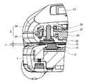
図1に示す如く、本体キャビネット(1)の内面には、複数の操作キー(11)が配備されると共に該操作キー(11)の下方に送話部(12)が凹設されており、本体キャビネット(1)の内部には、図2に示す如く、送話部(12)に集音面を向けたマイクロフォン(13)が配備されている。又、図1に示す如く、送話部(12)の両側には、本体キャビネット(1)の内面から離間する方向に突出する一対の凸部材(14)(14)が配備されており、本体キャビネット(1)の側面には、サイドキー(15)が配備されている。
尚、両凸部材(14)(14)は、シリコン系の弾性樹脂材料によって形成されている。As shown in FIG. 1, a plurality of operation keys (11) are provided on the inner surface of the main body cabinet (1), and a transmission section (12) is recessed below the operation keys (11). Inside the main body cabinet (1), as shown in FIG. 2, a microphone (13) having a sound collection surface facing the transmitter (12) is provided. Moreover, as shown in FIG. 1, a pair of convex members (14) and (14) projecting in a direction away from the inner surface of the main body cabinet (1) are disposed on both sides of the transmission section (12). Side keys (15) are provided on the side surfaces of the cabinet (1).
The both convex members (14) and (14) are made of a silicon-based elastic resin material.
蓋体キャビネット(2)の内面には、図1に示す如く、メインディスプレイ(21)が配備され、該メインディスプレイ(21)の上方には、両キャビネット(1)(2)を閉じた状態で送話部(12)と対向することとなる位置に、受話部(22)が配備されている。又、図2に示す如く、蓋体キャビネット(2)の背面には、サブディスプレイ(23)が配備されると共に、該サブディスプレイ(23)とヒンジ機構(3)との間には放音部(28)が配備されている。蓋体キャビネット(2)の内部には、受話部(22)に放音面を向けた第1スピーカ(24)が配備されると共に、放音部(28)に放音面を向けた骨伝導式の第2スピーカ(25)が配備されている。 As shown in FIG. 1, a main display (21) is arranged on the inner surface of the lid cabinet (2), and both cabinets (1) and (2) are closed above the main display (21). A receiver (22) is provided at a position facing the transmitter (12). In addition, as shown in FIG. 2, a sub-display (23) is provided on the back of the lid cabinet (2), and a sound emitting unit is provided between the sub-display (23) and the hinge mechanism (3). (28) is deployed. Inside the lid cabinet (2), a first speaker (24) with a sound emitting surface facing the receiver (22) is provided, and bone conduction with the sound emitting surface facing the sound emitting portion (28). A second speaker (25) of the type is provided.
図1及び図3に示す如く、蓋体キャビネット(2)は、内面キャビネット半体(20)と背面キャビネット半体(29)を接合して構成されており、両キャビネット半体(20)(29)は、受話部(22)の両側に設けられた一対のビス穴にビス(26)をそれぞれ螺合させることにより互いに接合されている。又、一対のビス(26)(26)はそれぞれ、シリコン系の弾性樹脂材料によって形成されるビスカバー(27)(27)によって覆われており、蓋体キャビネット(2)の内面に露出することはない。 As shown in FIGS. 1 and 3, the lid cabinet (2) is formed by joining the inner cabinet half (20) and the rear cabinet half (29). ) Are joined to each other by screwing screws (26) into a pair of screw holes provided on both sides of the receiver (22). The pair of screws (26) and (26) are covered by screw covers (27) and (27) formed of a silicon-based elastic resin material, respectively, and are not exposed to the inner surface of the lid cabinet (2). Absent.
図3に示す如く、ビスカバー(27)は、蓋体キャビネット(2)の内面から離間する方向に突出しており、両キャビネット(1)(2)を閉じた状態で本体キャビネット(1)の凸部材(14)と当接する。これによって、両キャビネット(1)(2)を閉じた場合、両キャビネット(1)(2)の内面間には隙間Cが形成され、凸部材(14)及びビスカバー(27)を除く両キャビネット(1)(2)の他の内面領域が互いに接触することはない。 As shown in FIG. 3, the screw cover (27) protrudes away from the inner surface of the lid cabinet (2), and the convex member of the main body cabinet (1) with both cabinets (1) and (2) closed. Contact with (14). Thus, when both cabinets (1) and (2) are closed, a gap C is formed between the inner surfaces of both cabinets (1) and (2), and both cabinets excluding the convex member (14) and screw cover (27) ( 1) The other inner surface areas of (2) do not contact each other.
上記本発明の折り畳み式携帯電話機においては、図1に示す如く、両キャビネット(1)(2)を開いた状態で送受話、メールの送受信及び送信メールの作成を行なうことが出来る。
両キャビネット(1)(2)を開くことにより、蓋体キャビネット(2)内面のメインディスプレイ(21)及び受話部(22)が露出すると共に、本体キャビネット(1)内面の操作キー(11)及び送話部(12)が露出する。このとき、キャビネット開閉検出器(図示省略)によって両キャビネット(1)(2)の開き状態が検出され、該検出に基づく検出信号が制御回路(図示省略)に供給される。制御回路は、前記検出信号に応じて、マイクロフォン(13)及び第1スピーカ(24)を機能させる。In the foldable mobile phone of the present invention, as shown in FIG. 1, it is possible to perform transmission / reception, transmission / reception of mail and creation of transmission mail with both cabinets (1) and (2) opened.
By opening both cabinets (1) and (2), the main display (21) and the receiver (22) on the inner surface of the lid cabinet (2) are exposed, and the operation keys (11) on the inner surface of the main body cabinet (1) and The transmitter (12) is exposed. At this time, an open state of both cabinets (1) and (2) is detected by a cabinet open / close detector (not shown), and a detection signal based on the detection is supplied to a control circuit (not shown). The control circuit causes the microphone (13) and the first speaker (24) to function according to the detection signal.
従って、着信時には、メインディスプレイ(21)の画面に相手の電話番号や氏名が表示され、これに応じて操作キー(11)によるオフフック操作を行なうことによって通話可能状態となり、ユーザは、受話部(22)を耳元に近づけると共に送話部(12)を口元に近づけて該着信に応答することが出来る。 Therefore, when receiving an incoming call, the telephone number and name of the other party are displayed on the screen of the main display (21), and in response to this, an off-hook operation by the operation key (11) is performed, so that a call can be made. It is possible to respond to the incoming call by bringing 22) close to the ear and the transmitter (12) close to the mouth.
又、メールの受信時には、操作キー(11)を操作することにより、メインディスプレイ(21)の画面に該受信メールの内容を表示してその内容を確認することが出来る。メール作成時には、操作キー(11)を操作することにより、メインディスプレイ(21)の画面にユーザが作成した文章が表示される。 Further, when receiving a mail, by operating the operation key (11), the contents of the received mail can be displayed on the screen of the main display (21) and confirmed. At the time of mail creation, the text created by the user is displayed on the screen of the main display (21) by operating the operation key (11).
上記本発明の折り畳み式携帯電話機をポケットや鞄に入れて携帯する場合には、図1の如く両キャビネット(1)(2)を開いた状態から両キャビネット(1)(2)を折り畳み、図2の如く両キャビネット(1)(2)を閉じる。これによって、メインディスプレイ(21)及び複数の操作キー(11)は両キャビネット(1)(2)の内側に隠れる。又、本体キャビネット(1)の凸部材(14)(14)と蓋体キャビネット(2)のビスカバー(27)(27)が互いに当接し、これによって、両キャビネット(1)(2)の内面間には隙間Cが形成される。従って、外力の作用によってメインディスプレイ(21)が複数の操作キー(11)に押圧されて破損する虞はない。又、メインディスプレイ(21)に複数の操作キー(11)が押圧されることによって誤作動が生じる虞はない。
又、送話部(12)は凹設されているので、蓋体キャビネット(2)の内面によって該送話部(12)が塞がれることはない。When the foldable mobile phone of the present invention is carried in a pocket or bag, both cabinets (1) and (2) are folded from the state where both cabinets (1) and (2) are opened as shown in FIG. Close both cabinets (1) and (2) as shown in 2. As a result, the main display (21) and the plurality of operation keys (11) are hidden inside the cabinets (1) and (2). Further, the convex members (14) and (14) of the main body cabinet (1) and the screw covers (27) and (27) of the lid cabinet (2) are brought into contact with each other, and thereby, between the inner surfaces of both cabinets (1) and (2). A gap C is formed in the. Therefore, there is no possibility that the main display (21) is pressed by the plurality of operation keys (11) and damaged by the action of external force. Further, there is no possibility of malfunction caused by pressing the plurality of operation keys (11) on the main display (21).
Further, since the transmission section (12) is recessed, the transmission section (12) is not blocked by the inner surface of the lid cabinet (2).
両キャビネット(1)(2)を閉じた状態でサイドキー(15)を押下して送受話モードに設定することにより、該折り畳み式携帯電話機を閉じた状態で送受話を行なうことが可能となる。
このとき、キャビネット開閉検出器によって両キャビネット(1)(2)の閉じ状態が検出され、該検出に基づく検出信号が制御回路に供給される。制御回路は、前記検出信号と、ハンズフリーモードに設定されたことに応じて、マイクロフォン(13)と第2スピーカ(25)を機能させる。これによって通話可能状態となり、ユーザは、放音部(28)を耳元に近づけると共に送話部(12)を口元に近づけて該着信に応答することが出来る。ここで、放音部(28)の第2スピーカ(25)は、骨伝導式のスピーカであるため、周囲の騒音が大きな場合にも、ユーザは第2スピーカ(25)の振動による通信相手の音声を明瞭に聞き取ることが出来る。By pressing the side key (15) with both cabinets (1) and (2) closed to set the transmission / reception mode, it becomes possible to perform transmission / reception with the folding cellular phone closed. .
At this time, the closed state of both cabinets (1) and (2) is detected by the cabinet open / close detector, and a detection signal based on the detection is supplied to the control circuit. The control circuit causes the microphone (13) and the second speaker (25) to function in response to the detection signal and the setting to the hands-free mode. As a result, it becomes possible to make a call, and the user can answer the incoming call by bringing the sound emitting unit (28) closer to the ear and the transmitter (12) closer to the mouth. Here, since the second speaker (25) of the sound emitting unit (28) is a bone-conduction type speaker, even when the surrounding noise is large, the user can communicate with the other party due to the vibration of the second speaker (25). The voice can be heard clearly.
このとき、放音部(28)の第2スピーカ(25)の大きな振動が蓋体キャビネット(2)に伝達され、該振動はビスカバー(27)(27)及び凸部材(14)(14)を介して本体キャビネット(1)にも伝達されることとなるが、ビスカバー(27)(27)及び凸部材(14)(14)は共にシリコン系の弾性樹脂材料によって形成されているため、前記振動は、ビスカバー(27)及び凸部材(14)の弾性によって効果的に吸収されることとなる。従って、本体キャビネット(1)が大きく振動することはなく、軽微な振動がマイクロフォン(13)に伝わるに過ぎない。 At this time, a large vibration of the second speaker (25) of the sound emitting section (28) is transmitted to the lid cabinet (2), and the vibration is applied to the screw covers (27) (27) and the convex members (14) (14). The screw covers (27), (27) and the convex members (14), (14) are both made of a silicon-based elastic resin material, so that the vibrations are transmitted to the main body cabinet (1). Is effectively absorbed by the elasticity of the screw cover (27) and the convex member (14). Therefore, the main body cabinet (1) does not vibrate greatly and only slight vibration is transmitted to the microphone (13).
又、第2スピーカ(25)の振動が蓋体キャビネット(2)内の空気に伝達され、該振動が第1スピーカ(24)に伝達されることにより第1スピーカ(24)も振動し、これによって第1スピーカ(24)から音波が発せられることとなるが、ビスカバー(27)と凸部材(14)との当接によって、蓋体キャビネット(2)の第1スピーカ(24)と本体キャビネット(1)のマイクロフォン(13)との間には、一定の距離が設けられているため、前記音波は蓋体キャビネット(2)から本体キャビネット(1)に向かう過程で減衰し、僅かにマイクロフォン(13)に伝わるに過ぎない。 The vibration of the second speaker (25) is transmitted to the air in the lid cabinet (2), and the vibration is transmitted to the first speaker (24), so that the first speaker (24) also vibrates. Sound waves are emitted from the first speaker (24) by the contact between the screw cover (27) and the convex member (14), and the first speaker (24) of the lid cabinet (2) and the main body cabinet ( Since a certain distance is provided between the
従って、両キャビネット(1)(2)を閉じた状態での第2スピーカ(25)の振動に伴うノイズ音の発生は極めて僅かであり、良好な通話状態を保つことが出来る。 Therefore, the generation of noise due to the vibration of the second speaker (25) when both cabinets (1) and (2) are closed is very small, and a good call state can be maintained.
凸部材(14)及びビスカバー(27)を形成するシリコンの硬度を60度と80度に設定して、本発明の折り畳み式携帯電話機の第1乃至第4の実施例を作製すると共に、ビスカバーを形成するシリコンの硬度を93度に設定し、該ビスカバーと当接する凸部を樹脂製の本体キャビネットに一体成型した比較例の折り畳み式携帯電話機を作製して、本発明の効果を確認した。
図4は、両キャビネット(1)(2)を閉じた状態で第2スピーカ(25)を振動させたときの第1乃至第4の実施例及び比較例のノイズ音の出力電圧を計測し、比較例の出力電圧に対する第1乃至第4実施例の出力電圧の低減率を示したグラフである。
尚、グラフの横軸は凸部材(14)の硬度を示し、グラフの縦軸は比較例の出力電圧に対する実施例の出力電圧の低減率を示しており、直線Aはビスカバー(27)の硬度を60度に設定した場合の低減率を示し、直線Bはビスカバー(27)の硬度を80度に設定した場合の低減率を示している。The first to fourth embodiments of the foldable mobile phone of the present invention are manufactured by setting the hardness of silicon forming the convex member (14) and the screw cover (27) to 60 degrees and 80 degrees, The hardness of the silicon to be formed was set to 93 degrees, and a foldable mobile phone of a comparative example in which a convex part that abuts against the screw cover was formed integrally with a resin main body cabinet was produced, and the effect of the present invention was confirmed.
FIG. 4 measures the output voltage of the noise sound of the first to fourth embodiments and the comparative example when the second speaker (25) is vibrated with both cabinets (1) and (2) closed. It is the graph which showed the reduction rate of the output voltage of the 1st thru | or 4th Example with respect to the output voltage of a comparative example.
The horizontal axis of the graph indicates the hardness of the convex member (14), the vertical axis of the graph indicates the reduction rate of the output voltage of the example with respect to the output voltage of the comparative example, and the straight line A indicates the hardness of the screw cover (27). Indicates the reduction rate when the angle is set to 60 degrees, and the straight line B indicates the reduction rate when the hardness of the screw cover (27) is set to 80 degrees.
図4のグラフから明らかな様に、凸部材(14)とビスカバー(27)を従来よりも硬度の低いシリコンによって形成することにより、ノイズ音は大幅に低減される。従って、本発明の折り畳み式携帯電話機によれば、ノイズ音は軽微であり、該ノイズ音が通話相手に不快感を与える虞はない。 As is apparent from the graph of FIG. 4, the noise noise is greatly reduced by forming the convex member (14) and the screw cover (27) with silicon having a hardness lower than that of the prior art. Therefore, according to the foldable mobile phone of the present invention, the noise sound is slight, and there is no possibility that the noise sound will cause uncomfortable feelings to the calling party.
又、本発明に係る折り畳み式携帯電話機においては、図5に示す如く、大出力の第2スピーカ(25a)を採用することも可能である。
該折り畳み式携帯電話機においては、両キャビネット(1)(2)を閉じた状態でサイドキーを押下してハンズフリーモードに設定することにより、第2スピーカ(25a)及びマイクロフォン(13)が機能し、これによって、電話機を手で保持することなく、机の上に置いた状態で送受話を行なうことが可能である。
この状態で、本体キャビネット(1)の背面を机の表面に接触させて両キャビネット(1)(2)を机の上に置くことにより、放音部(28)及び送話部(12)はユーザと対向することとなり、放音部(28)から通話相手の音声が発せられると共に、送話部(12)によってユーザの音声が集音されることによって、送受話が行なわれる。Further, in the foldable mobile phone according to the present invention, as shown in FIG. 5, it is possible to adopt a second speaker (25a) having a high output.
In the foldable mobile phone, the second speaker (25a) and the microphone (13) function by pressing the side key with both cabinets (1) and (2) closed to set the hands-free mode. As a result, it is possible to perform transmission and reception in a state where the telephone is placed on a desk without holding the telephone by hand.
In this state, by placing the back of the main cabinet (1) in contact with the desk surface and placing both cabinets (1) and (2) on the desk, the sound emitting section (28) and the transmitter section (12) The user's voice is emitted from the sound emission unit (28) and the voice of the user is collected by the transmission unit (12), so that transmission / reception is performed.
このとき、放音部(28)の第2スピーカ(25a)の大きな振動が蓋体キャビネット(2)に伝達され、該振動はビスカバー(27)(27)及び凸部材(14)(14)を介して本体キャビネット(1)にも伝達されることとなるが、該振動は、シリコン系の弾性樹脂材料によって形成されるビスカバー(27)(27)及び凸部材(14)(14)の弾性によって効果的に吸収されることとなる。
従って、第2スピーカ(25a)の振動に伴うノイズ音の発生は極めて僅かであり、良好な通話状態でハンズフリーによる送受話を行なうことが出来る。At this time, a large vibration of the second speaker (25a) of the sound emitting part (28) is transmitted to the lid cabinet (2), and the vibration is applied to the screw covers (27) (27) and the convex members (14) (14). The vibration is also transmitted to the main body cabinet (1) through the elasticity of the screw covers (27) (27) and the convex members (14) (14) formed of a silicon-based elastic resin material. It will be absorbed effectively.
Therefore, the generation of noise due to the vibration of the second speaker (25a) is extremely small, and hands-free transmission / reception can be performed in a good call state.
(1) 本体キャビネット
(11) 操作キー
(12) 送話部
(13) マイクロフォン
(14) 凸部材
(2) 蓋体キャビネット
(21) メインディスプレイ
(22) 受話部
(23) サブディスプレイ
(24) 第1スピーカ
(25) 第2スピーカ
(27) ビスカバー
(28) 放音部
(3) ヒンジ機構(1) Main unit cabinet
(11) Operation keys
(12) Transmitter
(13) Microphone
(14) Convex member
(2) Lid cabinet
(21) Main display
(22) Earpiece
(23) Sub display
(24) First speaker
(25) Second speaker
(27) Screw cover
(28) Sound emission part
(3) Hinge mechanism
Claims (3)
Translated fromJapanese本体キャビネット(1)の内面には、該内面から離間する方向に突出する弾性樹脂製の第1突起部が形成されると共に、蓋体キャビネット(2)の内面には、両キャビネット(1)(2)を閉じた状態で第1突起部と当接することとなる位置に、該内面から離間する方向に突出する弾性樹脂製の第2突起部が形成されており、両キャビネット(1)(2)を閉じた状態で両突起部が互いに当接して、両キャビネット(1)(2)の内面間に隙間が形成されることを特徴とする折り畳み式携帯端末機。The main body cabinet (1) and the lid cabinet (2) are connected to each other so as to be openable and closable, and the main body cabinet (1) is provided with a sound collecting unit. And a microphone (13) opposite to the lid cabinet (2), and a sound emitting section (28) is provided in the lid cabinet (2), and the sound emitting section (28) is provided inside the lid cabinet (2). In a foldable portable terminal in which a speaker that emits sound waves toward the
A first projection made of an elastic resin is formed on the inner surface of the main body cabinet (1) so as to protrude away from the inner surface, and both cabinets (1) ( 2), a second protrusion made of an elastic resin protruding in a direction away from the inner surface is formed at a position where it comes into contact with the first protrusion in a closed state, and both cabinets (1), (2) The folding portable terminal is characterized in that both projections abut each other in a closed state, and a gap is formed between the inner surfaces of the cabinets (1) and (2).
The folding portable terminal according to claim 1 or 2, wherein the speaker is a bone conduction speaker.
Priority Applications (1)
| Application Number | Priority Date | Filing Date | Title |
|---|---|---|---|
| JP2003377147AJP4542328B2 (en) | 2003-11-06 | 2003-11-06 | Foldable mobile terminal |
Applications Claiming Priority (1)
| Application Number | Priority Date | Filing Date | Title |
|---|---|---|---|
| JP2003377147AJP4542328B2 (en) | 2003-11-06 | 2003-11-06 | Foldable mobile terminal |
Publications (2)
| Publication Number | Publication Date |
|---|---|
| JP2005142835Atrue JP2005142835A (en) | 2005-06-02 |
| JP4542328B2 JP4542328B2 (en) | 2010-09-15 |
Family
ID=34687968
Family Applications (1)
| Application Number | Title | Priority Date | Filing Date |
|---|---|---|---|
| JP2003377147AExpired - Fee RelatedJP4542328B2 (en) | 2003-11-06 | 2003-11-06 | Foldable mobile terminal |
Country Status (1)
| Country | Link |
|---|---|
| JP (1) | JP4542328B2 (en) |
Cited By (17)
| Publication number | Priority date | Publication date | Assignee | Title |
|---|---|---|---|---|
| JP2007129373A (en)* | 2005-11-01 | 2007-05-24 | Univ Waseda | Method and system for adjusting sensitivity of microphone |
| JP2009077116A (en)* | 2007-09-20 | 2009-04-09 | Nec Tokin Corp | Bone conduction handset device |
| JP2012105084A (en)* | 2010-11-10 | 2012-05-31 | Fujitsu Ltd | Electronic device |
| JP2012238917A (en)* | 2011-04-28 | 2012-12-06 | Yuji Hosoi | Mobile phone |
| US9313306B2 (en) | 2010-12-27 | 2016-04-12 | Rohm Co., Ltd. | Mobile telephone cartilage conduction unit for making contact with the ear cartilage |
| US9392097B2 (en) | 2010-12-27 | 2016-07-12 | Rohm Co., Ltd. | Incoming/outgoing-talk unit and incoming-talk unit |
| US9479624B2 (en) | 2012-01-20 | 2016-10-25 | Rohm Co., Ltd. | Mobile telephone |
| US9485559B2 (en) | 2011-02-25 | 2016-11-01 | Rohm Co., Ltd. | Hearing system and finger ring for the hearing system |
| US9705548B2 (en) | 2013-10-24 | 2017-07-11 | Rohm Co., Ltd. | Wristband-type handset and wristband-type alerting device |
| US9729971B2 (en) | 2012-06-29 | 2017-08-08 | Rohm Co., Ltd. | Stereo earphone |
| US9742887B2 (en) | 2013-08-23 | 2017-08-22 | Rohm Co., Ltd. | Mobile telephone |
| US10013862B2 (en) | 2014-08-20 | 2018-07-03 | Rohm Co., Ltd. | Watching system, watching detection device, and watching notification device |
| US10356231B2 (en) | 2014-12-18 | 2019-07-16 | Finewell Co., Ltd. | Cartilage conduction hearing device using an electromagnetic vibration unit, and electromagnetic vibration unit |
| US10778824B2 (en) | 2016-01-19 | 2020-09-15 | Finewell Co., Ltd. | Pen-type handset |
| US10795321B2 (en) | 2015-09-16 | 2020-10-06 | Finewell Co., Ltd. | Wrist watch with hearing function |
| US10967521B2 (en) | 2015-07-15 | 2021-04-06 | Finewell Co., Ltd. | Robot and robot system |
| US11526033B2 (en) | 2018-09-28 | 2022-12-13 | Finewell Co., Ltd. | Hearing device |
Citations (7)
| Publication number | Priority date | Publication date | Assignee | Title |
|---|---|---|---|---|
| JP2001211241A (en)* | 2000-01-28 | 2001-08-03 | Sanyo Electric Co Ltd | Flip-type mobile phone |
| JP2001292209A (en)* | 2000-04-05 | 2001-10-19 | Nec Saitama Ltd | Foldable portable communication equipment |
| JP2002305569A (en)* | 2001-04-06 | 2002-10-18 | Nec Saitama Ltd | Foldable information terminal |
| JP2002320013A (en)* | 2001-04-20 | 2002-10-31 | Kyocera Corp | Foldable mobile terminal |
| JP2003152841A (en)* | 2001-11-13 | 2003-05-23 | Kenwood Corp | Foldable mobile phone |
| JP2003184927A (en)* | 2001-12-19 | 2003-07-03 | Nec Access Technica Ltd | Shock absorbing structure of folding type portable electronic device |
| JP2003273985A (en)* | 2002-03-13 | 2003-09-26 | Kenwood Corp | Portable telephone set |
- 2003
- 2003-11-06JPJP2003377147Apatent/JP4542328B2/ennot_activeExpired - Fee Related
Patent Citations (7)
| Publication number | Priority date | Publication date | Assignee | Title |
|---|---|---|---|---|
| JP2001211241A (en)* | 2000-01-28 | 2001-08-03 | Sanyo Electric Co Ltd | Flip-type mobile phone |
| JP2001292209A (en)* | 2000-04-05 | 2001-10-19 | Nec Saitama Ltd | Foldable portable communication equipment |
| JP2002305569A (en)* | 2001-04-06 | 2002-10-18 | Nec Saitama Ltd | Foldable information terminal |
| JP2002320013A (en)* | 2001-04-20 | 2002-10-31 | Kyocera Corp | Foldable mobile terminal |
| JP2003152841A (en)* | 2001-11-13 | 2003-05-23 | Kenwood Corp | Foldable mobile phone |
| JP2003184927A (en)* | 2001-12-19 | 2003-07-03 | Nec Access Technica Ltd | Shock absorbing structure of folding type portable electronic device |
| JP2003273985A (en)* | 2002-03-13 | 2003-09-26 | Kenwood Corp | Portable telephone set |
Cited By (32)
| Publication number | Priority date | Publication date | Assignee | Title |
|---|---|---|---|---|
| JP2007129373A (en)* | 2005-11-01 | 2007-05-24 | Univ Waseda | Method and system for adjusting sensitivity of microphone |
| JP2009077116A (en)* | 2007-09-20 | 2009-04-09 | Nec Tokin Corp | Bone conduction handset device |
| JP2012105084A (en)* | 2010-11-10 | 2012-05-31 | Fujitsu Ltd | Electronic device |
| US9894430B2 (en) | 2010-12-27 | 2018-02-13 | Rohm Co., Ltd. | Incoming/outgoing-talk unit and incoming-talk unit |
| US9313306B2 (en) | 2010-12-27 | 2016-04-12 | Rohm Co., Ltd. | Mobile telephone cartilage conduction unit for making contact with the ear cartilage |
| US9392097B2 (en) | 2010-12-27 | 2016-07-12 | Rohm Co., Ltd. | Incoming/outgoing-talk unit and incoming-talk unit |
| US10779075B2 (en) | 2010-12-27 | 2020-09-15 | Finewell Co., Ltd. | Incoming/outgoing-talk unit and incoming-talk unit |
| US9716782B2 (en) | 2010-12-27 | 2017-07-25 | Rohm Co., Ltd. | Mobile telephone |
| US9485559B2 (en) | 2011-02-25 | 2016-11-01 | Rohm Co., Ltd. | Hearing system and finger ring for the hearing system |
| US9980024B2 (en) | 2011-02-25 | 2018-05-22 | Rohm Co., Ltd. | Hearing system and finger ring for the hearing system |
| JP2012238917A (en)* | 2011-04-28 | 2012-12-06 | Yuji Hosoi | Mobile phone |
| US10778823B2 (en) | 2012-01-20 | 2020-09-15 | Finewell Co., Ltd. | Mobile telephone and cartilage-conduction vibration source device |
| US10079925B2 (en) | 2012-01-20 | 2018-09-18 | Rohm Co., Ltd. | Mobile telephone |
| US9479624B2 (en) | 2012-01-20 | 2016-10-25 | Rohm Co., Ltd. | Mobile telephone |
| US10158947B2 (en) | 2012-01-20 | 2018-12-18 | Rohm Co., Ltd. | Mobile telephone utilizing cartilage conduction |
| US10834506B2 (en) | 2012-06-29 | 2020-11-10 | Finewell Co., Ltd. | Stereo earphone |
| US9729971B2 (en) | 2012-06-29 | 2017-08-08 | Rohm Co., Ltd. | Stereo earphone |
| US10506343B2 (en) | 2012-06-29 | 2019-12-10 | Finewell Co., Ltd. | Earphone having vibration conductor which conducts vibration, and stereo earphone including the same |
| US10237382B2 (en) | 2013-08-23 | 2019-03-19 | Finewell Co., Ltd. | Mobile telephone |
| US10075574B2 (en) | 2013-08-23 | 2018-09-11 | Rohm Co., Ltd. | Mobile telephone |
| US9742887B2 (en) | 2013-08-23 | 2017-08-22 | Rohm Co., Ltd. | Mobile telephone |
| US10103766B2 (en) | 2013-10-24 | 2018-10-16 | Rohm Co., Ltd. | Wristband-type handset and wristband-type alerting device |
| US9705548B2 (en) | 2013-10-24 | 2017-07-11 | Rohm Co., Ltd. | Wristband-type handset and wristband-type alerting device |
| US10013862B2 (en) | 2014-08-20 | 2018-07-03 | Rohm Co., Ltd. | Watching system, watching detection device, and watching notification device |
| US10380864B2 (en) | 2014-08-20 | 2019-08-13 | Finewell Co., Ltd. | Watching system, watching detection device, and watching notification device |
| US10356231B2 (en) | 2014-12-18 | 2019-07-16 | Finewell Co., Ltd. | Cartilage conduction hearing device using an electromagnetic vibration unit, and electromagnetic vibration unit |
| US10848607B2 (en) | 2014-12-18 | 2020-11-24 | Finewell Co., Ltd. | Cycling hearing device and bicycle system |
| US11601538B2 (en) | 2014-12-18 | 2023-03-07 | Finewell Co., Ltd. | Headset having right- and left-ear sound output units with through-holes formed therein |
| US10967521B2 (en) | 2015-07-15 | 2021-04-06 | Finewell Co., Ltd. | Robot and robot system |
| US10795321B2 (en) | 2015-09-16 | 2020-10-06 | Finewell Co., Ltd. | Wrist watch with hearing function |
| US10778824B2 (en) | 2016-01-19 | 2020-09-15 | Finewell Co., Ltd. | Pen-type handset |
| US11526033B2 (en) | 2018-09-28 | 2022-12-13 | Finewell Co., Ltd. | Hearing device |
Also Published As
| Publication number | Publication date |
|---|---|
| JP4542328B2 (en) | 2010-09-15 |
Similar Documents
| Publication | Publication Date | Title |
|---|---|---|
| JP4542328B2 (en) | Foldable mobile terminal | |
| US7376447B2 (en) | Mobile telephone | |
| KR100767893B1 (en) | Mobile terminal | |
| JPH08139794A (en) | Portable telephone mechanism with built-in variable capacity receiver | |
| US20070098200A1 (en) | Acoustic apparatus using bone-conduction speaker | |
| JPWO2006059679A1 (en) | Mobile terminal device | |
| US7664539B2 (en) | Foldable portable terminal | |
| WO2003105450A1 (en) | Collapsible mobile telephone | |
| US20090156273A1 (en) | Loudspeaker for a Clamshell Wireless Communication Device | |
| JP3266132B2 (en) | Foldable mobile phone | |
| JP2008523714A (en) | A mobile terminal that changes the direction of the sound of a loudspeaker | |
| KR100690767B1 (en) | Mobile communication terminal | |
| JP2005159969A (en) | Mobile communication terminal | |
| CN1905581B (en) | Mobile terminal | |
| CN207802030U (en) | A kind of mobile communication equipment of receiver and screen sounder multiplexing | |
| CN112565495A (en) | Electronic device, control method, and computer-readable storage medium | |
| CN100505776C (en) | Foldable portable terminal equipment | |
| JP4394927B2 (en) | Foldable mobile terminal | |
| JP4332400B2 (en) | Foldable electronics | |
| KR200311931Y1 (en) | Sound Volume Up Structure of Mobile Phone | |
| KR100548398B1 (en) | Speaker device of portable terminal | |
| JP2002237763A (en) | Portable radio equipment | |
| JP2005217792A (en) | Folding portable phone | |
| JP2004266688A (en) | Mobile communication terminal | |
| JPH08102778A (en) | Transmitter |
Legal Events
| Date | Code | Title | Description |
|---|---|---|---|
| A621 | Written request for application examination | Free format text:JAPANESE INTERMEDIATE CODE: A621 Effective date:20061101 | |
| A711 | Notification of change in applicant | Free format text:JAPANESE INTERMEDIATE CODE: A712 Effective date:20080801 | |
| RD03 | Notification of appointment of power of attorney | Free format text:JAPANESE INTERMEDIATE CODE: A7423 Effective date:20080829 | |
| A977 | Report on retrieval | Free format text:JAPANESE INTERMEDIATE CODE: A971007 Effective date:20081120 | |
| A131 | Notification of reasons for refusal | Free format text:JAPANESE INTERMEDIATE CODE: A131 Effective date:20081201 | |
| A521 | Written amendment | Free format text:JAPANESE INTERMEDIATE CODE: A523 Effective date:20090127 | |
| A02 | Decision of refusal | Free format text:JAPANESE INTERMEDIATE CODE: A02 Effective date:20090810 | |
| A521 | Written amendment | Free format text:JAPANESE INTERMEDIATE CODE: A523 Effective date:20091110 | |
| A911 | Transfer of reconsideration by examiner before appeal (zenchi) | Free format text:JAPANESE INTERMEDIATE CODE: A911 Effective date:20100106 | |
| TRDD | Decision of grant or rejection written | ||
| A01 | Written decision to grant a patent or to grant a registration (utility model) | Free format text:JAPANESE INTERMEDIATE CODE: A01 Effective date:20100607 | |
| A01 | Written decision to grant a patent or to grant a registration (utility model) | Free format text:JAPANESE INTERMEDIATE CODE: A01 | |
| A61 | First payment of annual fees (during grant procedure) | Free format text:JAPANESE INTERMEDIATE CODE: A61 Effective date:20100625 | |
| R150 | Certificate of patent (=grant) or registration of utility model | Free format text:JAPANESE INTERMEDIATE CODE: R150 | |
| FPAY | Renewal fee payment (prs date is renewal date of database) | Free format text:PAYMENT UNTIL: 20130702 Year of fee payment:3 | |
| LAPS | Cancellation because of no payment of annual fees |