JP2005142719A - Message verification system, message verification method, and message verification program - Google Patents
Message verification system, message verification method, and message verification programDownload PDFInfo
- Publication number
- JP2005142719A JP2005142719AJP2003375572AJP2003375572AJP2005142719AJP 2005142719 AJP2005142719 AJP 2005142719AJP 2003375572 AJP2003375572 AJP 2003375572AJP 2003375572 AJP2003375572 AJP 2003375572AJP 2005142719 AJP2005142719 AJP 2005142719A
- Authority
- JP
- Japan
- Prior art keywords
- caller
- message
- verification
- code
- address
- Prior art date
- Legal status (The legal status is an assumption and is not a legal conclusion. Google has not performed a legal analysis and makes no representation as to the accuracy of the status listed.)
- Pending
Links
Images


Landscapes
- Information Transfer Between Computers (AREA)
Abstract
Translated fromJapaneseDescription
Translated fromJapaneseこの発明は、利用者端末から発信されたメッセージが当該メッセージのサービスを利用し得る正当な利用者から発信されたものであるかを検証するメッセージ検証システム、メッセージ検証方法およびメッセージ検証プログラムに関する。 The present invention relates to a message verification system, a message verification method, and a message verification program for verifying whether a message transmitted from a user terminal is transmitted from an authorized user who can use the service of the message.
従来より、インターネットなどのネットワーク上では、インスタントメッセージを利用者端末から受信して相手端末に伝達するサービスや、IP電話の呼メッセージを利用者端末から受け付けて相手端末を呼び出すサービス、電子メールを利用者端末から受信して相手端末に送信するサービスなど、IP(Internet Protocol)網を介して利用者端末からSIP(Session Initiation Protocol)等によるメッセージを受信してメッセージを処理するメッセージサービスが提供されている。 Conventionally, on networks such as the Internet, an instant message is received from a user terminal and transmitted to the other terminal, an IP phone call message is received from the user terminal and the other terminal is called, and e-mail is used. A message service that receives a message by a SIP (Session Initiation Protocol) or the like from a user terminal via an IP (Internet Protocol) network and processes the message, such as a service that is received from a user terminal and transmitted to a partner terminal is provided. Yes.
かかるメッセージサービスにおいては、利用者端末から発信されたメッセージがメッセージサービスを利用し得る正当な利用者から発信されたものであるかを検証した上でメッセージを処理することが一般的である。そして、このようなメッセージ検証の手法としては、特許文献1(特開平11−220496号公報)に開示されているように、発信者からメッセージとともにユーザIDおよびパスワードを受け付け、データベースに予め格納されたユーザIDおよびパスワードと比較して検証するパスワード認証が一般的である。 In such a message service, it is common to process a message after verifying whether the message sent from the user terminal is sent from a legitimate user who can use the message service. As such a message verification method, as disclosed in Patent Document 1 (Japanese Patent Laid-Open No. 11-22096), a user ID and a password are received together with a message from a caller and stored in a database in advance. Password authentication that is verified in comparison with a user ID and password is common.
ところで、上記した従来の技術では、メッセージが発信される毎にデータベースを参照してパスワード認証を行う必要があるので、データベースに負担がかかるという問題点の他に、メッセージ検証処理が遅滞するという問題点があった。特に、メールやインスタントメッセージのように、個々の短いデータグラムを個別のメッセージとして扱うメッセージサービスでは、データベースの参照回数が多くなってしまうので、パスワード認証を行うことによる問題点は大きかった。 By the way, in the above-mentioned conventional technology, it is necessary to perform password authentication by referring to the database every time a message is transmitted, so that there is a problem that the message verification processing is delayed in addition to the problem that the database is burdened. There was a point. In particular, message services that handle individual short datagrams as individual messages, such as e-mail and instant messages, have a large problem with password authentication because the number of database references increases.
そこで、この発明は、上述した従来技術の課題を解決するためになされたものであり、発信者のなりすましによる不正なメッセージの発信を防止するためのメッセージ検証を高速かつ軽負荷で実現することが可能なメッセージ検証システム、メッセージ検証方法およびメッセージ検証プログラムを提供することを目的とする。 Therefore, the present invention has been made to solve the above-described problems of the prior art, and it is possible to realize message verification for preventing unauthorized message transmission due to spoofing of a sender at high speed and with a light load. An object is to provide a message verification system, a message verification method, and a message verification program.
上述した課題を解決し、目的を達成するため、請求項1に係る発明は、利用者端末から発信されたメッセージが当該メッセージのサービスを利用し得る正当な利用者から発信されたものであるかを検証するメッセージ検証システムであって、前記正当な利用者であることを証明する発信者コードを、所定の鍵および前記利用者の発信者アドレスを引数とする演算処理を実行して生成する発信者コード生成手段と、前記利用者端末から前記メッセージとともに前記発信者コード生成手段によって生成された発信者コードを受信し、当該メッセージの発信者アドレスおよび前記所定の鍵を用いて前記発信者コードの有効性を検証する検証手段と、を備えたことを特徴とする。 In order to solve the above-described problems and achieve the object, the invention according to
また、請求項2に係る発明は、利用者端末から発信されたメッセージが当該メッセージのサービスを利用し得る正当な利用者から発信されたものであるかを検証するメッセージ検証システムであって、前記正当な利用者であることを証明する発信者コードを、所定の鍵および前記利用者の発信者アドレスを引数とする演算処理を実行して生成する発信者コード生成手段と、前記利用者端末から前記メッセージとともに、前記発信者コード生成手段によって生成された発信者コードで署名された署名データを受信し、前記メッセージの発信者アドレスおよび前記所定の鍵を用いて前記発信者コードの有効性を検証する検証手段と、を備えたことを特徴とする。 The invention according to
また、請求項3に係る発明は、上記の発明において、前記検証手段は、前記利用者端末から受信したメッセージの発信者アドレスおよび前記所定の鍵を引数として前記発信者コードの生成と同様の演算処理を実行して、前記発信者コードの有効性を検証する検証コードを生成する検証コード生成手段と、前記検証コード生成手段によって生成された検証コードで署名された検証用署名データを生成する検証用署名データ生成手段と、前記利用者端末から受信した署名データと前記検証用署名データ生成手段によって生成された検証用署名データとが一致するか否かを判定して、前記発信者コードの有効性を検証するコード検証手段と、を備えたことを特徴とする。 The invention according to
また、請求項4に係る発明は、上記の発明において、前記発信者コード生成手段および検証コード生成手段は、前記所定の鍵および発信者アドレスの他に、前記メッセージの発信が満たすべき発信条件をさらに引数とする演算処理を実行して前記発信者コードまたは検証コードを生成することを特徴とする。 According to a fourth aspect of the present invention, in the above invention, the sender code generation means and the verification code generation means satisfy a transmission condition to be satisfied by the transmission of the message in addition to the predetermined key and the sender address. Furthermore, the caller code or the verification code is generated by executing an arithmetic processing using an argument.
また、請求項5に係る発明は、上記の発明において、前記発信者コード生成手段および検証コード生成手段は、前記メッセージの発信を許可する利用者端末のネットワークアドレス、前記メッセージの発信を許可する期限若しくはこれらの組み合わせを前記発信条件として前記発信者コードまたは検証コードを生成することを特徴とする。 Further, in the invention according to
また、請求項6に係る発明は、上記の発明において、前記発信者コード生成手段によって生成された発信者コードとともに、当該発信者コードの生成に用いた発信条件を前記利用者に対して付与する付与手段と、前記利用者に付与された発信条件を前記メッセージとともに前記利用者端末から受信し、前記メッセージの発信が当該発信条件を満たすか否かを判定する発信条件判定手段と、を備え、前記検証コード生成手段は、前記発信条件判定手段によって前記メッセージの発信が前記発信条件を満たすと判定された場合にのみ、当該発信条件をさらに引数とする演算処理を実行して前記検証コードを生成することを特徴とする。 Further, in the invention according to claim 6, in the above invention, together with the caller code generated by the caller code generation means, the transmission condition used for generating the caller code is given to the user. Providing means, and transmission condition determination means for receiving the transmission condition assigned to the user together with the message from the user terminal, and determining whether or not the transmission of the message satisfies the transmission condition, The verification code generation unit generates the verification code by executing a calculation process using the transmission condition as an argument only when the transmission condition determination unit determines that the transmission of the message satisfies the transmission condition. It is characterized by doing.
また、請求項7に係る発明は、上記の発明において、前記利用者端末から前記メッセージを受信した際に、当該メッセージの受信状況に基づいて当該メッセージの発信が満たすべき発信条件を取得する発信条件取得手段を備え、前記検証コード生成手段は、前記発信条件取得手段によって取得した発信条件をさらに引数とする演算処理を実行して前記検証コードを生成することを特徴とする。 Further, the invention according to
また、請求項8に係る発明は、上記の発明において、前記発信者コード生成手段および検証コード生成手段は、複数の鍵のなかから前記発信条件に対応する鍵を選択し、当該選択した鍵、前記発信者アドレスおよび発信条件を引数とする演算処理を実行して前記発信者コードまたは検証コードを生成することを特徴とする。 The invention according to claim 8 is the above invention, wherein the sender code generation means and the verification code generation means select a key corresponding to the transmission condition from a plurality of keys, and the selected key, The caller code or the verification code is generated by executing a calculation process using the caller address and the call condition as arguments.
また、請求項9に係る発明は、上記の発明において、前記発信者コード生成手段および検証コード生成手段は、前記所定の鍵から定まる一方向関数に前記発信者アドレスおよび発信条件を入力することで前記発信者コードまたは検証コードを生成することを特徴とする。 According to a ninth aspect of the present invention, in the above invention, the sender code generation means and the verification code generation means input the sender address and the transmission condition into a one-way function determined from the predetermined key. The caller code or the verification code is generated.
また、請求項10に係る発明は、上記の発明において、前記発信者コード生成手段および検証コード生成手段は、前記所定の鍵を用いて前記発信者アドレスおよび発信条件を暗号化することで前記発信者コードまたは検証コードを生成することを特徴とする。 The invention according to
また、請求項11に係る発明は、上記の発明において、前記利用者端末とネットワークを介して接続される複数のサーバが前記検証コード生成手段をそれぞれ備え、前記複数のサーバは、前記所定の鍵をそれぞれ有し、前記検証コードをそれぞれ生成することを特徴とする。 According to an eleventh aspect of the present invention, in the above invention, a plurality of servers connected to the user terminal via a network each include the verification code generation means, and the plurality of servers include the predetermined key. And each of the verification codes is generated.
また、請求項12に係る発明は、上記の発明において、前記メッセージを着信する着信者の着信者アドレスおよび前記署名データからなる宛先アドレスのメールを受信するリメールサーバが前記検証手段を備え、当該リメールサーバは、前記発信者コードの有効性が認められた場合に、前記メールの宛先アドレスを前記着信者アドレスに置換して転送することを特徴とする。 Further, in the invention according to
また、請求項13に係る発明は、上記の発明において、前記リメールサーバによって転送されたメールに対する返信メールを受信するメール転送サーバをさらに備え、当該メール転送サーバは、前記発信者コードを再生成した後に、当該発信者コードを用いて前記署名データを再生成し、前記返信メールの発信元を前記着信者アドレスおよび署名データからなるアドレスに置換して転送することを特徴とする。 The invention according to
また、請求項14に係る発明は、利用者端末から発信されたメッセージが当該メッセージのサービスを利用し得る正当な利用者から発信されたものであるかを検証するメッセージ検証方法であって、前記正当な利用者であることを証明する発信者コードを、所定の鍵および前記利用者の発信者アドレスを引数とする演算処理を実行して生成する発信者コード生成工程と、前記利用者端末から前記メッセージとともに前記発信者コード生成工程によって生成された発信者コードを受信し、当該メッセージの発信者アドレスおよび前記所定の鍵を用いて前記発信者コードの有効性を検証する検証工程と、を含んだことを特徴とする。 The invention according to
また、請求項15に係る発明は、利用者端末から発信されたメッセージが当該メッセージのサービスを利用し得る正当な利用者から発信されたものであるかを検証するメッセージ検証方法であって、前記正当な利用者であることを証明する発信者コードを、所定の鍵および前記利用者の発信者アドレスを引数とする演算処理を実行して生成する発信者コード生成工程と、前記利用者端末から前記メッセージとともに、前記発信者コード生成工程によって生成された発信者コードで署名された署名データを受信し、前記メッセージの発信者アドレスおよび前記所定の鍵を用いて前記発信者コードの有効性を検証する検証工程と、を含んだことを特徴とする。 The invention according to
また、請求項16に係る発明は、上記の発明において、前記検証工程は、前記利用者端末から受信したメッセージの発信者アドレスおよび前記所定の鍵を引数として前記発信者コードの生成と同様の演算処理を実行して、前記発信者コードの有効性を検証する検証コードを生成する検証コード生成工程と、前記検証コード生成工程によって生成された検証コードで署名された検証用署名データを生成する検証用署名データ生成工程と、前記利用者端末から受信した署名データと前記検証用署名データ生成工程によって生成された検証用署名データとが一致するか否かを判定して、前記発信者コードの有効性を検証するコード検証工程と、を含んだことを特徴とする。 According to a sixteenth aspect of the present invention, in the above invention, the verification step includes a calculation similar to the generation of the caller code using the caller address of the message received from the user terminal and the predetermined key as arguments. A verification code generation step for generating a verification code for verifying the validity of the sender code by executing processing, and verification for generating verification signature data signed with the verification code generated by the verification code generation step The signature data generation step, whether the signature data received from the user terminal and the verification signature data generated by the verification signature data generation step match, And a code verification step for verifying the characteristics.
また、請求項17に係る発明は、上記の発明において、前記発信者コード生成工程および検証コード生成工程は、前記所定の鍵および発信者アドレスの他に、前記メッセージの発信が満たすべき発信条件をさらに引数とする演算処理を実行して前記発信者コードまたは検証コードを生成することを特徴とする。 According to a seventeenth aspect of the present invention, in the above invention, in the sender code generation step and the verification code generation step, in addition to the predetermined key and sender address, a transmission condition to be satisfied by the transmission of the message is satisfied. Furthermore, the caller code or the verification code is generated by executing an arithmetic processing using an argument.
また、請求項18に係る発明は、利用者端末から発信されたメッセージが当該メッセージのサービスを利用し得る正当な利用者から発信されたものであるかを検証する方法をコンピュータに実行させるメッセージ検証プログラムであって、前記正当な利用者であることを証明する発信者コードを、所定の鍵および前記利用者の発信者アドレスを引数とする演算処理を実行して生成する発信者コード生成手順と、前記利用者端末から前記メッセージとともに前記発信者コード生成手順によって生成された発信者コードを受信し、当該メッセージの発信者アドレスおよび前記所定の鍵を用いて前記発信者コードの有効性を検証する検証手順と、をコンピュータに実行させることを特徴とする。 The invention according to claim 18 is a message verification for causing a computer to execute a method for verifying whether a message transmitted from a user terminal is transmitted from a legitimate user who can use the service of the message. A caller code generation procedure for generating a caller code for proving that the user is a legitimate user by executing a calculation process using a predetermined key and the caller address of the user as arguments; The caller code generated by the caller code generation procedure together with the message is received from the user terminal, and the validity of the caller code is verified using the caller address of the message and the predetermined key. A verification procedure is executed by a computer.
また、請求項19に係る発明は、利用者端末から発信されたメッセージが当該メッセージのサービスを利用し得る正当な利用者から発信されたものであるかを検証する方法をコンピュータに実行させるメッセージ検証プログラムであって、前記正当な利用者であることを証明する発信者コードを、所定の鍵および前記利用者の発信者アドレスを引数とする演算処理を実行して生成する発信者コード生成手順と、前記利用者端末から前記メッセージとともに、前記発信者コード生成手順によって生成された発信者コードで署名された署名データを受信し、前記メッセージの発信者アドレスおよび前記所定の鍵を用いて前記発信者コードの有効性を検証する検証手順と、をコンピュータに実行させることを特徴とする。 The invention according to claim 19 is a message verification for causing a computer to execute a method for verifying whether a message transmitted from a user terminal is transmitted from a legitimate user who can use the service of the message. A caller code generation procedure for generating a caller code for proving that the user is a legitimate user by executing a calculation process using a predetermined key and the caller address of the user as arguments; The signature data signed by the sender code generated by the sender code generation procedure is received together with the message from the user terminal, and the sender is sent using the sender address of the message and the predetermined key. And a verification procedure for verifying the validity of the code.
また、請求項20に係る発明は、上記の発明において、前記検証手順は、前記利用者端末から受信したメッセージの発信者アドレスおよび前記所定の鍵を引数として前記発信者コードの生成と同様の演算処理を実行して、前記発信者コードの有効性を検証する検証コードを生成する検証コード生成手順と、前記検証コード生成手順によって生成された検証コードで署名された検証用署名データを生成する検証用署名データ生成手順と、前記利用者端末から受信した署名データと前記検証用署名データ生成手順によって生成された検証用署名データとが一致するか否かを判定して、前記発信者コードの有効性を検証するコード検証手順と、をコンピュータに実行させることを特徴とする。 According to a twentieth aspect of the present invention, in the above invention, the verification procedure is an operation similar to the generation of the caller code with the caller address of the message received from the user terminal and the predetermined key as arguments. A verification code generation procedure for generating a verification code for verifying the validity of the sender code by executing processing, and verification for generating verification signature data signed with the verification code generated by the verification code generation procedure The signature data generation procedure, whether the signature data received from the user terminal and the verification signature data generated by the verification signature data generation procedure match, and the validity of the sender code And a code verification procedure for verifying the property.
また、請求項21に係る発明は、上記の発明において、前記発信者コード生成手順および検証コード生成手順は、前記所定の鍵および発信者アドレスの他に、前記メッセージの発信が満たすべき発信条件をさらに引数とする演算処理を実行して前記発信者コードまたは検証コードを生成することを特徴とする。 Further, in the invention according to
請求項1、14または18の発明によれば、発信者アドレスおよび鍵を引数とする発信者コードを利用してメッセージ検証を行うので、パスワード認証のようなデータベースを参照する必要がなくなり、発信者のなりすましによる不正なメッセージの発信を防止するためのメッセージ検証を高速かつ軽負荷で実現することが可能になる。 According to the invention of
また、請求項2、15または19の発明によれば、発信者アドレスおよび鍵を引数とする発信者コードを利用してメッセージ検証を行うので、パスワード認証のようなデータベースを参照する必要がなくなり、発信者のなりすましによる不正なメッセージの発信を防止するためのメッセージ検証を高速かつ軽負荷で実現することが可能になる。さらに、発信者コードそのものではなく、発信者コードで署名された署名データを受け付けて検証するので、経路中にあるメッセージ中継装置が発信者コードをコピーして発信者になりすます行為も防止することが可能になる。 Further, according to the invention of
また、請求項3、16または20の発明によれば、検証に際して発信者アドレスおよび発信者コードを対応付けたデータベースから発信者コードを読み出すのではなく、演算処理によって発信者コード(検証コード)を生成するので、高速かつ軽負荷なメッセージ検証を実現することが可能になる。なお、発信者コードおよび検証コードを生成するための関数を発信者などに開示しないので、複数の利用者の結託による関数解読も防止することが可能になる。 According to the invention of
また、請求項4、17または21の発明によれば、発信条件も関係付けて発信者コードを生成するので、発信者コードの漏洩、傍受または偽造による不正が行われても(例えば、不正発信を試みる不正利用者と結託した発信者が自信の発信者コードを不正利用者に漏らしたとしても)、発信条件を満たさない限り不正なメッセージ発信として検出することができ、発信者のなりすましによる不正なメッセージの発信を確実に防止することが可能になるだけでなく、発信条件を満たさない他の不正なメッセージ発信を確実に防止することも可能になる。 Further, according to the invention of
また、請求項5の発明によれば、ネットワークアドレスや有効期限を満たさないメッセージを不正なメッセージ発信として排除することが可能になる。 According to the invention of
また、請求項6の発明によれば、発信条件を発信者コードに埋め込むことで利用者による発信条件の改ざんを防止していることを前提に、利用者端末からメッセージとともに受け付けた発信条件を検証に用いることができるので、発信条件をデータベースで管理して検証に用いる方式に比較して、高速かつ軽負荷なメッセージ検証を実現することが可能になる。さらに、発信条件を満たさない不正なメッセージ発信については検証コードを生成することなくメッセージ処理を拒否するので、一層高速なメッセージ検証を実現することも可能になる。 According to the invention of claim 6, the transmission condition received together with the message from the user terminal is verified on the assumption that the transmission condition is embedded in the caller code to prevent the user from falsifying the transmission condition. Therefore, it is possible to realize message verification at a high speed and with a light load, as compared with a method in which transmission conditions are managed in a database and used for verification. Furthermore, since the message processing is rejected without generating a verification code for an unauthorized message transmission that does not satisfy the transmission condition, it is possible to realize a higher-speed message verification.
また、請求項7の発明によれば、発信者コードの生成に用いた発信条件をデータベースで管理して検証に用いるのではなく、メッセージの受信状況から取得した発信条件を検証に用いるので、高速かつ軽負荷なメッセージ検証を実現することが可能になる。さらに、発信条件を利用者に開示しないので、発信条件の改ざんを回避して、不正なメッセージ発信を一層確実に防止することも可能になる。 Further, according to the invention of
また、請求項8の発明によれば、発信者コードおよび検証コードの生成に用いる鍵を固定することなく選択するので、鍵の解析を困難にして不正なメッセージ発信を抑止することも可能になる。 According to the invention of claim 8, since the key used for generating the sender code and the verification code is selected without being fixed, it becomes possible to make it difficult to analyze the key and to suppress illegal message transmission. .
また、請求項9の発明によれば、一方向関数によるコード生成を採用することで、暗号化による発信者コードの生成(暗号化による発信者コードの生成では、暗号化アルゴリズムのデータブロック長によってコードの長さが決まるため、短い発信者コードを生成することはできない。)とは異なり、短い発信者コードを生成することが可能になる。 Further, according to the invention of claim 9, by adopting code generation by a one-way function, generation of a sender code by encryption (in generation of a sender code by encryption, the data block length of the encryption algorithm Unlike a short caller code because the length of the code is determined), a short caller code can be generated.
また、請求項10の発明によれば、暗号化によるコード生成を採用することで、乱数列を用いたコード生成を行うこともできるので、既知平文攻撃や差分攻撃による鍵解析を一層困難にして不正なメッセージ発信を抑止することも可能になる。 Further, according to the invention of
また、請求項11の発明によれば、ユーザテーブルのようなデータベースを分散させたり、利用者ごとの署名鍵を各サーバ装置に配信したりすることなく、鍵の共有のみで各サーバ装置がメッセージ検証を行うことができるので、広範囲で大規模なメッセージ処理システムでも負荷を生じさせることなくなくメッセージ検証を行うことが可能になる。 According to the invention of
また、請求項12の発明によれば、いわゆるメールサービスにおいても、発信者のなりすましによる不正なメール発信を防止することが可能になる。 According to the invention of
また、請求項13の発明によれば、発信者が返信メールに対してさらに返信しようとする場合に、署名データを含んだ宛先アドレスを再び生成する必要はなく、通常のメール返信処理を発信者が実行するだけで、署名付きのメールを返信することが可能になる。 According to the invention of
以下に添付図面を参照して、この発明に係るメッセージ検証システム、メッセージ検証方法およびメッセージ検証プログラムの実施例を詳細に説明する。なお、以下では、本実施例で用いる主要な用語、本実施例に係るメッセージ検証システムの概要および特徴を説明した後に、種々の実施例(実施例1〜5)を説明する。 Exemplary embodiments of a message verification system, a message verification method, and a message verification program according to the present invention will be described below in detail with reference to the accompanying drawings. In the following, after describing the main terms used in the present embodiment, the outline and features of the message verification system according to the present embodiment, various embodiments (
[用語の説明]
最初に、本実施例で用いる主要な用語を説明する。本実施例で用いる「サービス」とは、IP(Internet Protocol)網を介して利用者端末からSIP(Session Initiation Protocol)等によるメッセージを受信して処理するサービスのことであり、例えば、インスタントメッセージを利用者端末から受信して相手端末に伝達するサービスや、IP電話の呼メッセージを利用者端末から受け付けて相手端末を呼び出すサービス、電子メールメッセージを利用者端末から受信して相手端末に送信するサービスなどがこれに該当する。[Explanation of terms]
First, main terms used in this embodiment will be described. The “service” used in this embodiment is a service that receives and processes a message by a SIP (Session Initiation Protocol) from a user terminal via an IP (Internet Protocol) network. A service that receives from a user terminal and transmits it to the other terminal, a service that receives an IP phone call message from the user terminal and calls the other terminal, and a service that receives an e-mail message from the user terminal and transmits it to the other terminal This is the case.
また、本実施例で用いる「メッセージ」とは、上記のサービスを利用する利用者の利用者端末からSIP等によって発信されるメッセージのことであり、例えば、インスタントメッセージや、IP電話の呼メッセージ、電子メールなどがこれに該当する。 Further, the “message” used in the present embodiment is a message transmitted by SIP or the like from a user terminal of a user who uses the above service. For example, an instant message, an IP phone call message, This includes e-mail.
また、本実施例で用いる「発信者アドレス(本実施例では「S」と表記する。)」とは、上記のサービスを利用する利用者(メッセージの発信者)が本来的に有している通信用の連絡先のことを指し、例えば、メールアドレスや、IP電話の電話番号などがこれに該当する。なお、かかる発信者アドレスは、上記のメッセージ発信にともなって利用者端末から発信されるものである。 Further, the “sender address (denoted as“ S ”in this embodiment)” used in the present embodiment is inherently possessed by the user (message sender) who uses the above service. This refers to a contact for communication. For example, an e-mail address or a telephone number of an IP phone corresponds to this. The sender address is sent from the user terminal along with the message sending.
また、本実施例で用いる「有効条件(特許請求の範囲に記載の「発信条件」に対応する。また、本実施例では「C」と表記する。)」とは、上記のメッセージの発信が満たすべき発信条件のことであり、例えば、図6に示すように、メッセージの発信を許可する利用者端末のネットワークアドレス(IPアドレス等)、メッセージの発信を許可する期限(若しくは期間)などを指定した条件がこれに該当する。 Further, “effective condition (corresponding to“ transmission condition ”described in the claims. In the present embodiment, expressed as“ C ”)” used in the present embodiment means that the above message is transmitted. For example, as shown in FIG. 6, the network address (IP address, etc.) of the user terminal that is permitted to send a message, the time limit (or period) that is allowed to send a message, etc., are specified. This is the case.
また、本実施例で用いる「発信者コード(本実施例では「T」と表記する。)」とは、上記のサービスを利用し得る正当な利用者であることを証明するためのコードであり、具体的には、上記の発信者アドレスおよび所定の鍵、さらには上記の有効条件を引数とする演算処理(一方向関数や暗号化による演算処理)を経て生成される。 Further, the “sender code (denoted as“ T ”in this embodiment)” used in the present embodiment is a code for proving that the user is a valid user who can use the above service. Specifically, it is generated through an arithmetic process (one-way function or arithmetic process by encryption) with the above-mentioned sender address and a predetermined key as well as the above-mentioned effective condition as arguments.
また、本実施例で用いる「署名データ(本実施例では「D(T)」や「D(R,T)」と表記する。)」とは、上記の発信者コードで署名されたデータのことであり、例えば、上記のメッセージにおけるヘッダ情報のうちからTOフィールド(宛先である着信者アドレスR)とDATEフィールドとを連結した文字列などを引数とし、上記の発信者コードを鍵とする鍵付きハッシュ関数から求められた値などがこれに該当する。 In addition, “signature data (in this embodiment,“ D (T) ”or“ D (R, T) ”)” used in the present embodiment refers to the data signed with the above sender code. For example, from the header information in the message described above, a key string using the sender code as a key, with a character string concatenating the TO field (destination recipient address R) and the DATE field as an argument, etc. A value obtained from an attached hash function corresponds to this.
また、本実施例で用いる「検証コード(本実施例では「V」と表記する。)」とは、上記の発信者コードの有効性(発信者のなりすまし等の不正が行われていないかどうか)を検証するためのコードであり、具体的には、上記の発信者コードの生成処理と同様の処理を実行することで生成される。 In addition, the “verification code (indicated by“ V ”in this embodiment)” used in this embodiment is the validity of the above-mentioned caller code (whether impersonation such as spoofing of the caller is not performed) ), Specifically, generated by executing the same processing as the above-described processing for generating the sender code.
また、本実施例で用いる「検証用署名データ(本実施例では「D(V)」や「D(R,V)」と表記する。)」とは、上記の検証コードで署名されたデータのことであり、具体的には、上記の署名データの生成処理と同様の処理を実行することで生成される。 Further, “verification signature data (in the present embodiment, expressed as“ D (V) ”or“ D (R, V) ”)” used in the present embodiment is data signed with the verification code. Specifically, it is generated by executing the same processing as the signature data generation processing described above.
[システムの概要および特徴]
続いて、本実施例に係るメッセージ検証システムの概要および特徴を説明する。本実施例に係るメッセージ検証システムは、概略的には、メッセージサービスを提供するサーバ装置(図1に示すメッセージ受信装置20など)において、利用者端末から発信されたメッセージが当該メッセージのサービスを利用し得る正当な利用者から発信されたものであるかを検証した上でメッセージを処理するものである。[System overview and features]
Next, the outline and features of the message verification system according to the present embodiment will be described. In general, the message verification system according to the present embodiment uses a service of a message transmitted from a user terminal in a server device (such as the
そして、かかるメッセージ検証システムでは、いわゆるパスワード認証ではなく、発信者アドレスおよび鍵を引数とする発信者コードを利用してメッセージ検証を行うこと等によって、発信者のなりすましによる不正なメッセージの発信を防止するためのメッセージ検証を高速かつ軽負荷で実現することを可能にしている点などに主たる特徴がある。以下に、この主たる特徴を簡単に説明する。 In such a message verification system, instead of using so-called password authentication, message verification is performed by using a sender code with a sender address and a key as arguments, thereby preventing unauthorized message transmission by the sender's spoofing. The main feature is that it enables message verification to be performed at high speed and with a light load. The main features will be briefly described below.
本実施例に係るメッセージ検証システムでは、利用者によるメッセージの発信に先立って、その利用者がメッセージサービスを利用し得る正当な利用者であることを証明するための発信者コードを生成して利用者に付与する。ここで、この利用者コードは、所定の鍵および当該利用者の発信者アドレス、さらには当該利用者によるメッセージの発信が満たすべき有効条件を引数とする演算処理を実行することで生成される。 In the message verification system according to the present embodiment, prior to the transmission of a message by a user, a caller code for certifying that the user is a valid user who can use the message service is generated and used. Grant to the person. Here, the user code is generated by executing a calculation process using, as arguments, a predetermined key and a sender address of the user, and further, an effective condition to be satisfied by the message transmission by the user.
そして、メッセージサービスを提供するサーバ装置(図1に示すメッセージ受信装置20など)においては、利用者端末からメッセージとともに、発信者コードで署名された署名データを受信し、メッセージの発信者アドレスを用いて発信者コードの有効性を検証する。より詳細には、先ずは、利用者端末から受信したメッセージの発信者アドレスおよび所定の鍵(上記の発信者コード生成に用いられた鍵)、さらには有効条件を用いて、発信者コードの生成と同様の演算処理を実行して検証コードを生成する。続けて、この検証コードで署名された検証用署名データを生成し、この検証用署名データと利用者端末から受信した署名データとが一致するか否かを判定して発信者コードの有効性を検証する。 Then, in a server device that provides a message service (such as the
その結果、サーバ装置(図1に示すメッセージ受信装置20など)においては、両者が一致する場合には、発信者コードが有効であるとしてメッセージ転送などのメッセージ処理を実行する。その一方、両者が一致しない場合には、発信者コードが無効である(すなわち、発信者アドレスが異なる発信者のなりすましによる不正なメッセージ、または、有効条件を満たさない不正なメッセージである)としてメッセージを破棄等する。 As a result, in the server device (such as the
上記したようなことから、本実施例によれば、発信者アドレスおよび鍵を引数とする発信者コードを利用してメッセージ検証を行うので、パスワード認証のようなデータベースを参照する必要がなくなり、発信者のなりすましによる不正なメッセージの発信を防止するためのメッセージ検証を高速かつ軽負荷で実現することが可能になる。また、本実施例によれば、発信者コードそのものではなく、発信者コードで署名された署名データを受け付けて検証するので、経路中にあるメッセージ中継装置が発信者コードをコピーして発信者になりすます行為も防止することが可能になる。 As described above, according to this embodiment, since message verification is performed using a caller code having a caller address and a key as arguments, there is no need to refer to a database such as password authentication. Message verification for preventing an unauthorized message from being transmitted due to impersonation by a person can be realized at high speed and with a light load. Also, according to the present embodiment, since the signature data signed with the caller code is received instead of the caller code itself, the message relay device in the route copies the caller code to the caller. Spoofing can also be prevented.
また、本実施例によれば、検証に際して発信者アドレスおよび発信者コードを対応付けたデータベースから発信者コードを読み出すのではなく、演算処理によって発信者コード(検証コード)を生成するので、高速かつ軽負荷なメッセージ検証を実現することが可能になる。なお、発信者コードおよび検証コードを生成するための関数を発信者などに開示しないので、複数の利用者の結託による関数解読も防止することが可能になる。 Further, according to the present embodiment, the sender code (verification code) is generated by the arithmetic processing instead of reading the sender code from the database in which the sender address and the sender code are associated with each other at the time of verification. It is possible to realize light load message verification. In addition, since the function for generating the sender code and the verification code is not disclosed to the sender or the like, it is possible to prevent the function from being deciphered by collusion of a plurality of users.
さらに、本実施例によれば、有効条件も関係付けて発信者コードを生成するので、発信者コードの漏洩、傍受または偽造による不正が行われても(例えば、不正発信を試みる不正利用者と結託した発信者が自信の発信者コードを不正利用者に漏らしたとしても)、有効条件を満たさない限り不正なメッセージ発信として検出することができ、発信者のなりすましによる不正なメッセージの発信を確実に防止することが可能になるだけでなく、有効条件を満たさない他の不正なメッセージ発信を確実に防止することも可能になる。 Furthermore, according to the present embodiment, since the sender code is generated in relation to the validity condition, even if the sender code is leaked, intercepted or forged by fraud (for example, an unauthorized user who tries to make an unauthorized call Even if the colluding caller leaks a confident caller code to an unauthorized user), it can be detected as a fraudulent message transmission as long as the validity conditions are not met, and transmission of a fraudulent message by the spoofing of the caller is ensured. This makes it possible to reliably prevent other unauthorized message transmissions that do not satisfy the valid conditions.
実施例1では、インスタントメッセージやIP電話の呼メッセージを利用者端末から受け付けてメッセージ処理するサービスに本発明を適用した場合を説明する。なお、以下では、本実施例1に係るメッセージ検証システムの構成を説明した後に、システム全体の処理手順を説明し、最後に実施例1の効果等を説明する。 In the first embodiment, a case will be described in which the present invention is applied to a service that accepts an instant message or an IP telephone call message from a user terminal and processes the message. In the following, after describing the configuration of the message verification system according to the first embodiment, the processing procedure of the entire system will be described, and finally the effects of the first embodiment will be described.
[メッセージ検証システムの構成(実施例1)]
まず最初に、図1を用いて、実施例1に係るメッセージ検証システムの構成を説明する。図1は、実施例1に係るメッセージ検証システムの構成を示すブロック図である。同図に示すように、このメッセージ検証システムは、インターネット3と接続されるIP網2やLAN4を介して、発信者端末1と、発信者認証装置10と、複数のメッセージ受信装置20とを相互に通信可能に接続して構成される。なお、発信者端末1は請求項2などに記載の利用者端末に対応し、発信者認証装置10は請求項2などに記載の発信者コード生成手段に対応し、メッセージ受信装置20は請求項2などに記載の検証手段および請求項11に記載のサーバに対応する。[Configuration of Message Verification System (Example 1)]
First, the configuration of the message verification system according to the first embodiment will be described with reference to FIG. FIG. 1 is a block diagram illustrating the configuration of the message verification system according to the first embodiment. As shown in the figure, this message verification system allows a
このうち、発信者端末1は、メッセージサービスを利用する利用者であってメッセージを発信する発信者が使用する利用者端末であり、主として、発信者認証装置10にアクセスして発信者認証の後に発信者コードの発行を受ける役割や、発信者コードとともに有効条件を発信者認証装置10から取得する役割、発信者コードを用いて署名データを生成する役割、署名データおよび有効条件とともにメッセージをメッセージ受信装置20に送信する役割などを有する。なお、かかる発信者端末1は、既知のパーソナルコンピュータやワークステーション、家庭用ゲーム機、インターネットTV、PDA、あるいは携帯電話やPHSの如き移動体通信端末などで実現される。 Of these, the
発信者認証装置10は、メッセージサービスを利用し得る利用者の情報を管理する業者(ISP業者など)の装置であり、主として、発信者端末1との間で利用者の認証を行う役割、利用者認証が成功した利用者に対して発信者コードを発行する役割などを有する。また、メッセージ受信装置20は、メッセージサービスを提供する業者(ISP業者など)の装置であり、主として、発信者端末1から受信したメッセージを検証して処理する役割などを有する。なお、発信者認証装置10およびメッセージ受信装置20は、既知のサーバコンピュータで実現される。以下に、これらの各装置の機能構成を詳細に説明する。 The
[発信者端末の構成(実施例1)]
発信者端末1は、Webブラウザやインスタントメッセージ用ソフト、IP電話用ソフトなど、各種のソフトウェアがインストールされた既知の利用者端末であるが、特に本発明に密接に関連するものとしては、図1に示すように、署名生成部1aを備える。[Configuration of Caller Terminal (Example 1)]
The
この署名生成部1aは、発信者コードを用いて署名データを生成する処理部である。具体的には、メッセージ受信装置20に送信しようとしているメッセージにおけるヘッダ情報のうちからTOフィールド(宛先である着信者アドレスR)とDATEフィールドとを連結した文字列を引数とし、発信者コードTを鍵とする鍵付きハッシュ関数の値を求め、この値の下位16バイトを抽出することで署名データD(T)を生成する。つまり、下位16バイトの値が署名データD(T)となる。なお、鍵付きハッシュ関数は、RFC−2104に記載のものなどの公知のものでもよく、また、鍵付きハッシュ関数の構成に用いるハッシュ関数も、MD−5やSHA−1などの公知のものでもよい。 The
[発信者認証装置の構成(実施例1)]
発信者認証装置10は、図1に示すように、認証通信部11と、ユーザテーブル12と、発信者認証部13と、マスター鍵テーブル14と、発信者コード生成部15とを備える。なお、認証通信部11は請求項6に記載の付与手段に対応し、発信者コード生成部14は請求項2、4、5、8または9に記載の発信者コード生成手段に対応する。[Configuration of Caller Authentication Device (Example 1)]
As shown in FIG. 1, the
このうち、認証通信部11は、いわゆるHTTPの通信プロトコルなどにしたがって、発信者端末1との間における通信を制御する処理部である。具体的には、発信者端末1からアクセス要求を受け付けると、ユーザ認証ページを発信者端末1に送信してユーザ名(発信者アドレスS)およびパスワードの入力を受け付ける。また、発信者認証が成功して発信者コードTが生成されると、この発信者コードTおよび当該発信者コードTの生成に用いた有効条件Cを発信者端末1に対して送信する。なお、発信者コードTの送信に際しては、TLSやS/MIMEなどの暗号化処理を利用することで、発信者コードTの傍受を防止することが望ましい。 Among these, the
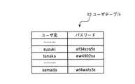
ユーザテーブル12は、メッセージサービスを利用し得る利用者の情報を記憶する手段であり、具体的には、図2に例示するように、利用者ごとに、発信者認証に用いられるユーザ名およびパスワードを記憶して構成される。このユーザテーブル12はデータベースで実現される。なお、本実施例では、発信者認証に用いられるユーザ名と、利用者の発信者アドレスSのユーザ名とが一致する例を挙げているため、ユーザテーブル12には各利用者の発信者アドレスSそのものを記憶していないが、両者が異なる場合には、発信者アドレスSも記憶することとなる。 The user table 12 is a means for storing information on users who can use the message service. Specifically, as illustrated in FIG. 2, a user name and a password used for caller authentication for each user. Is stored and configured. This user table 12 is realized by a database. In the present embodiment, an example in which the user name used for caller authentication matches the user name of the user's caller address S is given, and therefore the caller address of each user is stored in the user table 12. Although S itself is not memorize | stored, when both differ, the sender address S will also be memorize | stored.
マスター鍵テーブル14は、発信者コードTの生成に用いる鍵(マスター鍵)を記憶する手段であり、具体的には、図3に例示するように、マスター鍵を一定期間ごとに更新する趣旨から、発信者コードTに関係づけられる有効期限(有効条件の一つ)の範囲ごとに、複数のインデックス番号(0〜3)に対応付けて、それぞれの鍵(K)を記憶して構成される。なお、このマスター鍵テーブル14は、マスター鍵のデータを含む電子ファイルを発信者認証装置10の蓄積領域に保存することで実現される。ただし、発信者コードTの生成を高速に実現するために、後述の発信者コード生成部15は、プログラム実行プロセス起動時に電子ファイルのデータをプロセス内のメモリに読み込み、起動中はメモリをマスター鍵テーブル14として利用する。 The master key table 14 is a means for storing a key (master key) used for generating the sender code T. Specifically, as illustrated in FIG. 3, the master key is updated at regular intervals. Each key (K) is stored in association with a plurality of index numbers (0 to 3) for each range of expiration dates (one of valid conditions) related to the sender code T. . The master key table 14 is realized by storing an electronic file including master key data in the storage area of the
発信者認証部13は、発信者端末1の発信者がメッセージサービスを利用し得る正当な利用者であるか否かを認証する処理部である。具体的には、発信者端末1から発信者アドレスS(ユーザ名)およびパスワードを受け付けると、これに対応するユーザ名およびパスワードがユーザテーブル12に記憶されているか否かを認証する。その結果、発信者の認証が成功すれば、発信者コード生成部15に発信者アドレスS(ユーザ名)および発信者端末1のIPアドレスを受け渡す。その一方、発信者の認証が失敗すれば、その旨を発信者端末1に送信する。なお、発信者認証の手法は任意であり、例えば、ダイジェスト認証や公開鍵を用いる手法を採用してもよい。 The
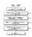
発信者コード生成部15は、マスター鍵テーブル14に記憶された鍵K、発信者認証部13から受け取った発信者アドレスSおよび有効条件Cを引数とする演算処理(一方向関数を用いた処理)を実行して発信者コードTを生成する処理部である。以下に、図5および図6を用いて、発信者コード生成部15による発信者コードTの生成処理を説明する。図5は、実施例1による発信者コード生成処理の流れを示すフローチャートであり、図6は、有効条件Cの構成例を示す図である。 The caller
図6に示すように、有効条件Cは、有効条件の種別を表す種別情報と有効条件(例えば、IPアドレス指定、有効期限指定などの発信条件)の内容とを「コンマ(,)」で結合して構成される。ここで、「IPアドレス指定(N)」は、メッセージの発信を許可する発信者端末1のネットワークアドレスを指定する条件であり、発信者認証部13から受け取ったIPアドレスの値をもって規定する。また、「有効期限指定(E)」は、メッセージの発信を許可する期限を指定する条件であり、現在(発信者認証の成功時)の年月日時から所定期間後の年月日時の値をもって規定する。 As shown in FIG. 6, the valid condition C is a combination of type information indicating the type of valid condition and the contents of valid conditions (for example, transmission conditions such as IP address designation and expiration date designation) with “comma (,)”. Configured. Here, “IP address designation (N)” is a condition for designating the network address of the
そして、このようにして規定された有効条件C、さらには、マスター鍵テーブル14に記憶された鍵Kと発信者認証部13から受け取った発信者アドレスSとを用いて発信者コードTが生成される。すなわち、発信者コード生成部15は、図5に示すように、有効条件Cに基づいてマスター鍵テーブル14からマスター鍵Kmを選択する(ステップS501)。この選択は、有効条件Cのハッシュ値の下位2ビットをインデックス番号として求めた後、有効条件C内の有効期限を有効期限範囲に含み、かつ、インデックス番号が一致する鍵をマスター鍵Kmとして選択することによって行われる。 Then, the caller code T is generated using the validity condition C thus defined, and further, the key K stored in the master key table 14 and the caller address S received from the
続いて、発信者コード生成部15は、発信者アドレスSと有効条件Cとを連結した文字列xを生成する(ステップS502)。そして、この文字列xを引数とし、マスター鍵Kmを鍵とする鍵付きハッシュ関数の値を求め、この値の下位16バイトを抽出することで発信者コードTを生成する(ステップS503)。つまり、下位16バイトの値が発信者コードTとなる。このようにして生成された発信者コードTおよび当該発信者コードTの生成に用いた有効条件Cは発信者端末1に送信される。 Subsequently, the sender
なお、本実施例では、いわゆるKeyedHashアルゴリズムによって発信者コードTを生成するが、具体的なハッシュ関数としてはSHA−1を用いた例を示している。ただし、発信者コード生成部15と後述する検証コード生成部25とでアルゴリズムが共有されていればハッシュ関数は任意であり、例えばMD5を用いてもよい。 In the present embodiment, the sender code T is generated by the so-called KeyedHash algorithm, but an example using SHA-1 as a specific hash function is shown. However, the hash function is arbitrary as long as the algorithm is shared between the sender
[メッセージ受信装置の構成(実施例1)]
メッセージ受信装置20は、図1に示すように、メッセージ受信部21と、メッセージ処理部22と、有効条件判定部23と、マスター鍵テーブル24と、検証コード生成部25と、検証用署名生成部26と、コード検証部27とを備える。なお、有効条件判定部23は請求項6に記載の発信条件判定手段に対応し、検証コード生成部25は請求項3、4、5、6、8、9または11に記載の検証コード生成手段に対応し、検証用署名生成部26は請求項3に記載の検証用署名データ生成手段に対応し、コード検証部27は請求項3に記載のコード検証手段に対応する。[Configuration of Message Receiving Device (Example 1)]
As shown in FIG. 1, the
このうち、メッセージ受信部21は、いわゆるUDP/IPやTCP/IPの通信プロトコルなどにしたがって、発信者端末1からメッセージを受信する処理部である。具体的には、発信者アドレスSと、発信者認証装置10から利用者が受け取った発信者コードTで署名された署名データD(T)と、同じく発信者認証装置10から利用者が受け取った有効条件Cとを含んだメッセージを発信者端末1から受信する。 Among these, the
メッセージ処理部22は、メッセージ受信部21が発信者端末1から受信したメッセージを処理する処理部である。具体的には、受信したインスタントメッセージの伝達や、IP電話における呼の確立などのメッセージ処理を実行するが、後述の有効条件判定やコード検証が失敗した場合には、これらのメッセージ処理を実行することなくメッセージの廃棄等を実行する。 The
マスター鍵テーブル24は、上記した発信者認証装置10が備えるマスター鍵テーブル14との間で、LAN4を介して同期が取られているテーブルである。つまり、マスター鍵テーブル24も、図3に例示したものと同様の情報を記憶する。 The master key table 24 is a table that is synchronized with the master key table 14 included in the
有効条件判定部23は、発信者端末1から受信した有効条件Cをメッセージの発信が満たしているか否かを判定する処理部である。具体的には、有効条件CにIPアドレス指定(N)が含まれていれば、メッセージを伝達したUDP/IPパケット等のソースIPアドレスと有効条件C内のIPアドレスが一致するか否かを判定し、さらに、有効条件Cに有効期限指定(E)が含まれていれば、メッセージを受信した時点が有効条件C内の有効期限の以前であるか否かを判定する。その結果、全ての有効条件を満たす場合には、後述の検証コード生成部25による処理が実行されるが、有効条件を一つでも満たさない場合には、上記のメッセージ処理部22によってメッセージの廃棄等が実行される。 The validity
検証コード生成部25は、マスター鍵テーブル24に記憶された鍵K、発信者端末1からメッセージとともに受信した発信者アドレスSおよび有効条件Cを引数とする演算処理(一方向関数を用いた処理)を実行して検証コードVを生成する処理部である。具体的には、図5に示したように、上記した発明者認証装置10の発信者コード生成部15による発信者コードTの生成と同様の演算処理を実行して検証コードVを生成する。 The verification
検証用署名作成部26は、検証コード生成部25によって生成された検証コードVで署名された検証用署名データD(V)を生成する処理部である。具体的には、上記した発信者端末1の署名生成部1aによる署名データD(T)の生成と同様の処理を実行して検証用署名データD(V)を生成する。 The verification
コード検証部27は、発信者端末1から受信した署名データD(T)と検証用署名作成部26によって生成された検証用署名データD(V)とが一致するか否かを判定して、発信者コードTの有効性を検証する処理部である。その結果、両者が一致する場合には、上記のメッセージ処理部22によってメッセージ処理が実行されるが、両者が一致しない場合には、メッセージ処理部22によってメッセージの廃棄等が実行される。なお、発信者コードTの生成に用いた発信者アドレスSとは異なる発信者アドレスSからメッセージが発信された場合や、発信者コードTの生成に用いた有効条件Cが改ざんされて異なる有効条件Cが発信されたような場合には、署名データD(T)と検証用署名データD(V)とが一致しなくなる。 The
[システム全体の処理手順(実施例1)]
次に、図4を用いて、実施例1に係るメッセージ検証システムの処理手順を説明する。図4は、実施例1による処理手順を示すシーケンス図である。[Processing Procedure of Entire System (Example 1)]
Next, the processing procedure of the message verification system according to the first embodiment will be described with reference to FIG. FIG. 4 is a sequence diagram illustrating a processing procedure according to the first embodiment.
同図に示すように、発信者認証装置10は、発信者端末1からアクセス要求を受け付けると(ステップS401)、ユーザ認証ページを発信者端末1に送信してユーザ名(発信者アドレスS)およびパスワードの入力を受け付ける(ステップS402)。そして、発信者端末1からユーザ名およびパスワードを含んだ認証要求を受信すると(ステップS403)、発信者認証装置10は、これに対応するユーザ名およびパスワードがユーザテーブル12に記憶されているか否か判定して発信者を認証する(ステップS404)。 As shown in the figure, when the
その結果、発信者の認証が失敗すれば、その旨を発信者端末1に送信するが、これとは反対に発信者の認証が成功した場合には、発信者認証装置10は、マスター鍵テーブル14に記憶された鍵K、発信者認証部13から受け取った発信者アドレスSおよび有効条件Cを引数とする演算処理(一方向関数を用いた処理)を実行して発信者コードTを生成する(ステップS405)。 As a result, if the authentication of the caller fails, the fact is transmitted to the
そして、発信者認証装置10は、認証応答として、生成した発信者コードTおよび当該発信者コードTの生成に用いた有効条件Cを発信者端末1に対して送信する(ステップS406)。これによって、発信者コードTが有効である限り、発信者は発信者コードTを用いてメッセージを発信することとなる。 Then, the
すなわち、メッセージの発信に際して、発信者端末1では、メッセージ受信装置20に送信しようとしているメッセージにおけるヘッダ情報のうちからTOフィールド(宛先である着信者アドレスR)とDATEフィールドとを連結した文字列を引数とし、発信者コードTを鍵とする鍵付きハッシュ関数の値を求め、この値の下位16バイトを抽出することで署名データD(T)を生成する(ステップS407)。 That is, when the message is transmitted, the
そして、メッセージ受信装置20は、発信者アドレスSと、発信者認証装置10から利用者が受け取った有効条件Cと、同じく発信者認証装置10から受け取った発信者コードTで署名された署名データD(T)とを含んだメッセージを発信者端末1から受信する(ステップS408)。続いて、メッセージ受信装置20は、発信者端末1から受信した有効条件Cをメッセージの発信が満たしているか否かを判定する(ステップS409)。 Then, the
この判定の結果、有効条件を一つでも満たさなければ、メッセージの廃棄等を実行するが、これとは反対に全ての有効条件を満たす場合には、メッセージ受信装置20は、マスター鍵テーブル24に記憶された鍵K、発信者端末1からメッセージとともに受信した発信者アドレスSおよび有効条件Cを引数とする演算処理を実行して検証コードVを生成する(ステップS410)。 If at least one valid condition is not satisfied as a result of this determination, message discarding or the like is executed. On the contrary, if all valid conditions are satisfied, the
続けて、メッセージ受信装置20は、ステップS410で生成した検証コードVで署名された検証用署名データD(V)を生成し(ステップS411)、さらに、発信者端末1から受信した署名データD(T)とステップS411で生成した検証用署名データD(V)とが一致するか否かを判定して、発信者コードTの有効性を検証する(ステップS412)。 Subsequently, the
この検証の結果、両者が一致しなければ、メッセージの廃棄等を実行するが、これとは反対に両者が一致する場合には、メッセージ受信装置20は、発信者端末1から受信したインスタントメッセージの伝達や、IP電話における呼の確立などのメッセージ処理を実行する(ステップS413)。 As a result of this verification, if the two do not match, the message is discarded or the like. On the contrary, if both match, the
[実施例1の効果等]
上述してきたように、実施例1によれば、発信者アドレスおよび鍵を引数とする発信者コードを利用してメッセージ検証を行うので、パスワード認証のようなデータベースを参照する必要がなくなり、発信者のなりすましによる不正なメッセージの発信を防止するためのメッセージ検証を高速かつ軽負荷で実現することが可能になる。[Effects of Example 1]
As described above, according to the first embodiment, since message verification is performed using a caller code having a caller address and a key as arguments, there is no need to refer to a database such as password authentication. It is possible to implement message verification for preventing unauthorized message transmission by spoofing at high speed and with a light load.
また、実施例1によれば、発信者コードそのものではなく、発信者コードTで署名された署名データD(T)を受け付けて検証するので、経路中にあるメッセージ中継装置(例えば、メッセージ受信装置20など)が発信者コードTをコピーして発信者になりすます行為も防止することが可能になる。 Further, according to the first embodiment, since the signature data D (T) signed with the caller code T is received instead of the caller code itself, the message relay device (for example, the message reception device) in the path is verified. 20) can also prevent the act of impersonating the caller by copying the caller code T.
また、実施例1によれば、検証に際してデータベース(発信者アドレスSおよび発信者コードTを対応付けたデータベース)から発信者コードTを読み出すのではなく、演算処理によって発信者コードTと同等の検証コードVを生成するので、高速かつ軽負荷なメッセージ検証を実現することが可能になる。なお、発信者コードTおよび検証コードVを生成するための関数を発信者などに開示しないので、複数の利用者の結託による関数解読も防止することが可能になる。 Further, according to the first embodiment, the verification is equivalent to the caller code T by a calculation process instead of reading the caller code T from the database (database in which the caller address S and the caller code T are associated) at the time of verification. Since the code V is generated, it is possible to realize high-speed and light load message verification. In addition, since the function for generating the sender code T and the verification code V is not disclosed to the sender or the like, it is also possible to prevent the function from being decrypted by collusion of a plurality of users.
また、実施例1によれば、有効条件Cも関係付けて発信者コードTを生成するので、発信者コードTの漏洩、傍受または偽造による不正が行われても(例えば、不正発信を試みる不正利用者と結託した発信者が自信の発信者コードを不正利用者に漏らしたとしても)、有効条件Cを満たさない限り不正なメッセージ発信として検出することができ、発信者のなりすましによる不正なメッセージの発信を確実に防止することが可能になるだけでなく、有効条件Cを満たさない他の不正なメッセージ発信を確実に防止することも可能になる。より具体的には、ネットワークアドレスや有効期限を満たさないメッセージを不正なメッセージ発信として排除することが可能になる。 In addition, according to the first embodiment, since the sender code T is generated in association with the validity condition C, even if the sender code T is leaked, intercepted or forged by fraud (for example, fraud attempting to make an unauthorized call) Even if the caller who collaborates with the user leaks a confident caller code to an unauthorized user), it can be detected as an illegal message transmission as long as the valid condition C is not satisfied. As well as other unauthorized message transmissions that do not satisfy the valid condition C can be reliably prevented. More specifically, a message that does not satisfy the network address or expiration date can be excluded as an illegal message transmission.
また、実施例1によれば、有効条件Cを発信者コードTに埋め込むことで利用者による有効条件Cの改ざんを防止していることを前提に、発信者端末1からメッセージとともに受け付けた有効条件Cを検証に用いることができるので、有効条件Cをデータベースで管理して検証に用いる方式に比較して、高速かつ軽負荷なメッセージ検証を実現することが可能になる。さらに、有効条件Cを満たさない不正なメッセージ発信については検証コードTを生成することなくメッセージ処理を拒否するので、一層高速なメッセージ検証を実現することも可能になる。 Further, according to the first embodiment, the valid condition received together with the message from the
また、実施例1によれば、発信者コードTおよび検証コードVの生成に用いる鍵を固定することなく選択するので、鍵の解析を困難にして不正なメッセージ発信を抑止することも可能になる。 Further, according to the first embodiment, since the keys used for generating the sender code T and the verification code V are selected without being fixed, it is possible to make it difficult to analyze the key and to suppress illegal message transmission. .
また、実施例1によれば、一方向関数によるコード生成を採用することで、暗号化による発信者コードTの生成(暗号化による発信者コードTの生成では、暗号化アルゴリズムのデータブロック長によってコードの長さが決まるため、短い発信者コードTを生成することはできない。)とは異なり、短い発信者コードTを生成することが可能になる。 In addition, according to the first embodiment, by adopting code generation by a one-way function, the generation of the sender code T by encryption (in the generation of the sender code T by encryption, the data block length of the encryption algorithm Since the length of the code is determined, it is not possible to generate a short caller code T. In contrast, it is possible to generate a short caller code T.
また、実施例1によれば、ユーザテーブルのようなデータベースを分散させたり、利用者ごとの署名鍵を各メッセージ受信装置20に配信したりすることなく、鍵の共有のみで各メッセージ受信装置20がメッセージ検証を行うことができるので、複数のメッセージ受信装置20を備える広範囲で大規模なメッセージ処理システムでも負荷を生じさせることなくなくメッセージ検証を行うことが可能になる。 Further, according to the first embodiment, each
ところで、上記の実施例1では、発信者コードTの生成に用いた有効条件Cを利用者に付与した上で発信者端末1から受け付けることにしたが、本発明はこれに限定されるものではなく、有効条件Cの種別や組合せを固定とし、メッセージ受信装置20が別途の手段で有効条件Cを取得するようにしてもよい。そこで、実施例2では、有効条件Cを利用者に付与しない場合を説明する。 By the way, in Example 1 described above, the valid condition C used to generate the caller code T is given to the user and then accepted from the
[メッセージ検証システムの構成(実施例2)]
最初に、図7を用いて、実施例2に係るメッセージ検証システムの構成を説明する。図7は、実施例2に係るメッセージ検証システムの構成を示すブロック図である。同図に示すように、このメッセージ検証システムは、インターネット3と接続されるIP網2やLAN4を介して、発信者端末1と、発信者認証装置30と、複数のメッセージ受信装置40とを相互に通信可能に接続して構成される。なお、発信者端末1は請求項2などに記載の利用者端末に対応し、発信者認証装置30は請求項2などに記載の発信者コード生成手段に対応し、メッセージ受信装置40は請求項2などに記載の検証手段および請求項11に記載のサーバに対応する。[Configuration of Message Verification System (Example 2)]
Initially, the structure of the message verification system based on Example 2 is demonstrated using FIG. FIG. 7 is a block diagram illustrating the configuration of the message verification system according to the second embodiment. As shown in the figure, this message verification system allows a
このうち、発信者端末1は、上記の実施例1で説明した発信者端末1に対応するものであり、これと基本的には同様の機能を有する。ただし、実施例2では、発信者認証装置30から発信者端末1へ発信者コードTのみを送信する(有効条件Cは送信しない)ので、発信者端末1は、メッセージとともに署名データのみをメッセージ受信装置40に送信する(有効条件Cは送信しない)。 Among these, the
また、実施例2では、後述するように、所定時間ごと(例えば、1時間ごと)に有効な発信者コードTを生成するので、発信者端末1は、所定時間ごと(例えば、毎時0分になるごと)に発信者認証装置30にアクセスし、次の所定時間に有効な発信者コードTの発行を受ける。 Further, in the second embodiment, as will be described later, a valid caller code T is generated every predetermined time (for example, every hour), so that the
発信者認証装置30は、上記の実施例1で説明した発信者認証装置10に対応するものであり、これと基本的には同様の機能を有する。つまり、図7に示す認証通信部31、ユーザテーブル32、発信者認証部33、マスター鍵テーブル34および発信者コード生成部35は、図1に示した認証通信部11、ユーザテーブル12、発信者認証部13、マスター鍵テーブル14および発信者コード生成部15と基本的に同様の機能を果たす。 The
ただし、実施例2では、有効条件Cの種別や組合せを固定とし、所定時間ごと(例えば、1時間ごと)に有効な発信者コードTを生成することを実現するために、発信者コード生成部35は、有効条件Cとして、発信者端末1のIPアドレスを指定IPアドレスとして指定するとともに、現在(発信者認証の成功時)時刻の次の時の0分を有効期限として指定する。つまり、現在が12時30分であれば13時0分を有効期限として指定する。 However, in the second embodiment, in order to realize that the type and combination of the valid condition C are fixed and the valid caller code T is generated every predetermined time (for example, every hour), the caller
そして、発信者コード生成部35は、このようにして指定された有効条件C、さらには、マスター鍵テーブル14に記憶された鍵Kと発信者認証部33から受け取った発信者アドレスSとを用いて、図5に示したように、発信者コードTを生成する。なお、実施例2では、発信者認証装置30は、上記したように、発信者端末1へ発信者コードTのみを送信し、当該発信者コードTの生成に用いた有効条件Cは送信しない。 Then, the caller
メッセージ受信装置40は、上記の実施例1で説明したメッセージ受信装置20に対応するものであり、図7に示すように、図1に示した有効条件判定部23の代わりに有効条件取得部43を備えるが、メッセージ受信装置20と基本的には同様の機能を有する。つまり、図7に示すメッセージ受信部41、メッセージ処理部42、マスター鍵テーブル44、検証コード生成部45、検証用署名生成部46およびコード検証部47は、図1に示したメッセージ受信部21、メッセージ処理部22、マスター鍵テーブル24、検証コード生成部25、検証用署名生成部26およびコード検証部27と同様の機能を果たす。なお、有効条件取得部43は請求項7に記載の発信条件取得手段に対応し、検証コード生成部45は請求項7に記載の検証コード生成手段に対応する。 The
ただし、実施例2では、メッセージ受信部41は、上記したように、発信者端末1からメッセージとともに署名データのみを受信する(有効条件Cは受信しない)。また、有効条件取得部43は、発信者端末1からメッセージを受信した際に、当該メッセージの受信状況に基づいて当該メッセージの発信が満たすべき有効条件を取得する。つまり、メッセージを伝達したUDP/IPパケット等のソースIPアドレス(発信者端末1のIPアドレス)を指定IPアドレスの有効条件として取得するとともに、現在(メッセージの受信時)の時刻の次の時の0分を有効期限の有効条件として取得する。 However, in the second embodiment, as described above, the
さらに、実施例2では、検証コード生成部45は、有効条件取得部43によって取得された有効条件Cを用いて検証コードVを生成する。したがって、検証コードVで署名された検証用署名データD(V)が発信者端末1から受信した署名データD(T)と一致しない場合には、有効条件取得部43によって取得した有効条件Cが発信者コードTの生成に用いたものと異なっているものとして、結果的に有効条件を判定することができる。 Furthermore, in the second embodiment, the verification
[システム全体の処理手順(実施例2)]
次に、図8を用いて、実施例2に係るメッセージ検証システムの処理手順を説明する。図8は、実施例2による処理手順を示すシーケンス図である。[Processing Procedure of Entire System (Example 2)]
Next, the processing procedure of the message verification system according to the second embodiment will be described with reference to FIG. FIG. 8 is a sequence diagram illustrating a processing procedure according to the second embodiment.
同図に示すように、発信者認証装置30は、図4に示した実施例1と同様の手順を経て発信者を認証する(ステップS801〜S804)。その結果、発信者の認証が失敗すれば、その旨を発信者端末1に送信するが、これとは反対に発信者の認証が成功した場合には、発信者認証装置30は、マスター鍵テーブル14に記憶された鍵K、発信者認証部13から受け取った発信者アドレスSおよび有効条件Cを引数とする演算処理(一方向関数を用いた処理)を実行して発信者コードTを生成する(ステップS805)。なお、有効条件Cとしては、発信者端末1のIPアドレスが指定IPアドレスとして指定されるとともに、現在(発信者認証の成功時)の時刻の次の時の0分が有効期限として指定される。 As shown in the figure, the
そして、発信者認証装置30は、認証応答として、生成した発信者コードTを発信者端末1に対して送信する(ステップS806)。ただし、発信者コードTの生成に用いた有効条件Cは発信者端末1に送信されない。これによって、発信者コードTが有効である限り、発信者は発信者コードTを用いてメッセージを発信することとなる。 Then, the
すなわち、メッセージの発信に際して、発信者端末1では、図4に示した実施例1と同様の手順を経て署名データD(T)を生成する(ステップS807)。そして、メッセージ受信装置40は、発信者アドレスSと、発信者認証装置10から受け取った発信者コードTで署名された署名データD(T)とを含んだメッセージを発信者端末1から受信する(ステップS808)。なお、発信者コードTの生成に用いた有効条件Cは発信者端末1から受信しない。 That is, when sending a message, the
続いて、メッセージ受信装置40は、メッセージを伝達したUDP/IPパケット等のソースIPアドレス(発信者端末1のIPアドレス)を指定IPアドレスの有効条件Cとして取得するとともに、現在(メッセージの受信時)の時刻の次の時の0分を有効期限の有効条件Cとして取得する(ステップS809)。 Subsequently, the
そして、メッセージ受信装置40は、マスター鍵テーブル44に記憶された鍵K、発信者端末1からメッセージとともに受信した発信者アドレスS、および、ステップS809で取得した有効条件Cを引数とする演算処理を実行して検証コードVを生成する(ステップS810)。これに続いて、メッセージ受信装置40は、図4に示した実施例1と同様の手順を経て、検証用署名データD(V)の生成、署名データD(T)と検証用署名データD(V)との一致判定、メッセージ処理を実行する(ステップS811〜S813)。 Then, the
[実施例2の効果等]
上述してきたように、実施例2によれば、発信者コードTの生成に用いた有効条件Cをデータベースで管理して検証に用いるのではなく、メッセージの受信状況から取得した有効条件Cを検証に用いるので、高速かつ軽負荷なメッセージ検証を実現することが可能になる。さらに、有効条件Cを利用者に開示しないので、有効条件Cの改ざんを回避して、不正なメッセージ発信を一層確実に防止することも可能になる。[Effects of Example 2 and the like]
As described above, according to the second embodiment, the effective condition C used for generating the sender code T is not managed by the database and used for the verification, but the effective condition C acquired from the reception status of the message is verified. Therefore, it is possible to realize message verification at high speed and light load. Furthermore, since the effective condition C is not disclosed to the user, it is possible to prevent the illegal condition from being transmitted more reliably by avoiding falsification of the effective condition C.
ところで、上記の実施例1および2では、一方向関数を用いた演算処理によって発信者コードTおよび検証コードVを生成する場合を説明したが、本発明はこれに限定されるものではなく、暗号化を用いた演算処理によって発信者コードTおよび検証コードVを生成するようにしてもよい。そこで、実施例3では、暗号化によって発信者コードTおよび検証コードVを生成する場合を説明する。 In the first and second embodiments described above, the case where the sender code T and the verification code V are generated by the arithmetic processing using the one-way function has been described. However, the present invention is not limited to this, The caller code T and the verification code V may be generated by an arithmetic process using the conversion. Therefore, in the third embodiment, a case where the sender code T and the verification code V are generated by encryption will be described.
[メッセージ検証システムの構成(実施例3)]
図9は、実施例3に係るメッセージ検証システムの構成を示すブロック図である。同図に示すように、このメッセージ検証システムは、インターネット3と接続されるIP網2やLAN4を介して、発信者端末1と、発信者認証装置50と、複数のメッセージ受信装置60とを相互に通信可能に接続して構成される。なお、発信者端末1は請求項2などに記載の利用者端末に対応し、発信者認証装置50は請求項2などに記載の発信者コード生成手段に対応し、メッセージ受信装置60は請求項2などに記載の検証手段および請求項11に記載のサーバに対応する。[Configuration of Message Verification System (Example 3)]
FIG. 9 is a block diagram illustrating the configuration of the message verification system according to the third embodiment. As shown in the figure, this message verification system allows a
このうち、発信者端末1は、上記の実施例1で説明した発信者端末1に対応するものであり、これと基本的には同様の機能を有する。また、発信者認証装置50は、上記の実施例1で説明した発信者認証装置10に対応するものであり、図9に示すように、乱数列テーブル56をさらに備えるが、発信者認証装置10と基本的には同様の機能を有する。 Among these, the
つまり、図9に示す認証通信部51、ユーザテーブル52、発信者認証部53、マスター鍵テーブル54および発信者コード生成部55は、図1に示した認証通信部11、ユーザテーブル12、発信者認証部13、マスター鍵テーブル14および発信者コード生成部15と基本的に同様の機能を果たす。なお、発信者コード生成部55は請求項10に記載の発信者コード生成手段に対応する。 That is, the
ここで、発信者認証装置50の乱数列テーブル56は、発信者コードTの生成に用いる乱数列を記憶する手段であり、具体的には、図10に例示するように、複数の乱数列それぞれを一意に特定するためのインデックス番号に対応付けて、それぞれの乱数列を記憶して構成される。 Here, the random number sequence table 56 of the
また、発信者認証装置50の発信者コード生成部55は、マスター鍵テーブル54に記憶された鍵K、発信者アドレスSおよび有効条件Cを引数とする演算処理(暗号化を用いた処理)を実行して発信者コードTを生成する処理部である。以下に、図11を用いて、発信者コード生成部55による発信者コードTの生成処理を説明する。図11は、実施例3による発信者コード生成処理の流れを示すフローチャートである。 In addition, the caller
同図に示すように、発信者コード生成部55は、実施例1と同様の手順でマスター鍵テーブル54からマスター鍵Kmを選択する(ステップS1101)。さらに、発信者コード生成部55は、有効条件Cを引数とする選択関数によって乱数列テーブル56からある一つの乱数列rを選択する(ステップS1102)。 As shown in the figure, the
続けて、発信者コード生成部55は、発信者アドレスSに乱数列rをEXORで加算して文字列S.rを生成する(ステップS1103)。そして、発信者コード生成部55は、有効条件Cと文字列S.rとをつなげたデータをマスター鍵Kmで暗号化し、暗号化結果を発信者コードTとして生成する(ステップS1104)。なお、このようにして生成された発信者コードTおよび当該発信者コードの生成に用いた有効条件Cは、実施例1と同様、発信者端末1に送信される。 Subsequently, the
図9に戻ると、メッセージ受信装置60は、上記の実施例1で説明したメッセージ受信装置20に対応するものであり、同図に示すように、乱数列テーブル68をさらに備えるが、メッセージ受信装置20と基本的には同様の機能を有する。つまり、図9に示すメッセージ受信部61、メッセージ処理部62、有効条件判定部63、マスター鍵テーブル64、検証コード生成部65、検証用署名生成部66およびコード検証部67は、図1に示したメッセージ受信部21、メッセージ処理部22、有効条件判定部23、マスター鍵テーブル24、検証コード生成部25、検証用署名生成部26およびコード検証部27と同様の機能を果たす。なお、検証コード生成部65は請求項10に記載の検証コード生成手段に対応する。 Returning to FIG. 9, the
ここで、メッセージ受信装置60の乱数列テーブル68は、上記の乱数列テーブル56との間でLAN4を介して同期が取られているテーブルであり、図10に例示したものと同様の情報を記憶する。そして、メッセージ受信装置60の検証コード生成部65は、図11に示したように、上記した発明者認証装置50の発信者コード生成部55による発信者コードTの生成と同様の演算処理を実行して検証コードVを生成する。 Here, the random number sequence table 68 of the
[実施例3の効果等]
上述してきたように、実施例3によれば、暗号化によるコード生成を採用することで、乱数列を用いたコード生成を行うこともできるので、既知平文攻撃や差分攻撃による鍵解析を一層困難にして不正なメッセージ発信を抑止することも可能になる。[Effects of Example 3 and the like]
As described above, according to the third embodiment, since code generation using a random number sequence can be performed by adopting code generation by encryption, it is more difficult to perform key analysis using a known plaintext attack or differential attack. It is also possible to suppress unauthorized message transmission.
なお、実施例3では、メッセージ受信装置60でも暗号化によって検証コードVを生成して発信者コードTを検証する場合を説明したが、本発明はこれに限定されるものではなく、メッセージ受信装置60で受信した発信者コードTを復号化することによって発信者コードTの有効性(発信者コードTから復元された発信者アドレスSや有効条件Cの有効性)を検証するようにしてもよい。なお、この場合には、有効条件Cを発信者コードTから復元することができるので、有効条件Cを取得するための別手段を不要にすることも可能になる。 In the third embodiment, the case where the
ところで、上記の実施例1〜3では、インスタントメッセージやIP電話の呼メッセージを利用者端末から受け付けてメッセージ処理するサービスに本発明を適用した場合を説明したが、本発明はこれに限定されるものではなく、利用者端末からメールを受け付けて処理するサービスにも同様に適用することができる。 In the first to third embodiments, the case where the present invention is applied to a service that receives an instant message or an IP telephone call message from a user terminal and processes the message has been described. However, the present invention is not limited to this. However, the present invention can be similarly applied to a service that accepts mail from a user terminal and processes it.
そこで、実施例4では、利用者端末から発信されたメールが当該メールのサービスを利用し得る正当な利用者から発信されたものであるかを検証するメッセージ検証システムであって、特に、メッセージ検証を発信者メールサーバではなく経路上のリメールサーバで行う点、メッセージ検証に用いる署名データを利用者端末だけではなくメール転送サーバでも生成する点を主たる特徴とする場合を説明する。 Thus, in the fourth embodiment, there is provided a message verification system that verifies whether a mail transmitted from a user terminal is transmitted from a legitimate user who can use the service of the mail. The case where the main feature is that the message is performed not by the sender mail server but by the re-mail server on the route, and the signature data used for message verification is generated not only by the user terminal but also by the mail transfer server will be described.
[メッセージ検証システムの構成(実施例4)]
最初に、図12を用いて、実施例4に係るメッセージ検証システムの構成を説明する。図12は、実施例4に係るメッセージ検証システムの構成を示すブロック図である。同図に示すように、このメッセージ検証システムは、インターネット3やIP網2、LAN4を介して、発信者端末1と、着信者端末5と、発信者認証装置70と、リメールサーバ80と、メール転送サーバ90と、発信者メールサーバ6と、着信者メールサーバ7とを相互に通信可能に接続して構成される。なお、発信者端末1は請求項2などに記載の利用者端末に対応し、発信者認証装置10は請求項2などに記載の発信者コード生成手段に対応し、リメールサーバ80は請求項12に記載のリメールサーバに対応し、メール転送サーバ90は請求項12に記載のメール転送サーバに対応する。[Configuration of Message Verification System (Example 4)]
Initially, the structure of the message verification system based on Example 4 is demonstrated using FIG. FIG. 12 is a block diagram illustrating the configuration of the message verification system according to the fourth embodiment. As shown in the figure, this message verification system includes a
このうち、発信者端末1および着信者端末5は、少なくとも電子メールソフトがインストールされた、既知のパーソナルコンピュータやワークステーション、家庭用ゲーム機、インターネットTV、PDA、あるいは携帯電話やPHSの如き移動体通信端末などである。より詳細には、発信者端末1は、着信者にメールを発信する発信者が使用する端末であり、実施例1の発信者端末1と同様の役割を有するとともに、このメールに対する返信メールを着信者から受信する役割もある。一方、着信者端末5は、発信者から送信されたメールを着信する着信者が使用する端末であり、このメールに対する返信メールを発信者に発信する役割もある。 Of these, the
発信者メールサーバ6および着信者メールサーバ7は、いわゆる既知のメールサーバである。より詳細には、発信者メールサーバ6は、発信者端末1からメールを受け付けるとともに、このメールに対する返信メールを発信者端末1に送信する役割を有し、また、着信者メールサーバ7は、メールを着信者端末5に送信するとともに、このメールに対する返信メールを発信者端末5から受け付ける役割を有する。 The sender mail server 6 and the
発信者認証装置70は、上記の実施例1で説明した発信者認証装置10に対応するものであり、これと基本的には同様の機能を有する。また、リメールサーバ80は、発信者端末1(発信者メールサーバ6)からメールを受け付けて、正当な利用者から発信されたものであるかを検証した上でメールを着信者端末5(着信者メールサーバ7)に転送するサーバである。さらに、メール転送サーバ90は、着信者端末5(着信者メールサーバ7)から返信メールを受け付けて、この返信メールを発信者端末1(発信者メールサーバ6)に転送するサーバである。以下に、本実施例4の主たる特徴を担う発信者端末1、発信者認証装置70、リメールサーバ80、メール転送サーバ90の構成を詳細に説明する。 The
[発信者端末の構成(実施例4)]
発信者端末1は、Webブラウザや電子メールソフトなど、各種のソフトウェアがインストールされた既知の利用者端末であるが、特に本発明に密接に関連するものとしては、図12に示すように、署名生成部1bを備える。[Configuration of Caller Terminal (Example 4)]
The
この署名生成部1bは、発信者コードを用いて署名データを生成する処理部である。具体的には、発信しようとしているメールの着信者が有する着信者アドレスRの文字列を引数とし、発信者コードTを鍵とする鍵付きハッシュ関数の値を求め、この値の下位30ビットをBASE32符号化によって6文字の文字列に変換することで署名データD(R,T)を生成する。つまり、図13に例示するような「ertg5e」の如き6文字の文字列が署名データD(R,T)となる(ステップS1308の宛先アドレス参照)。 The
そして、発信者端末1は、作成した署名データD(R,T)をメールのヘッダ情報のTOフィールドに書き込んでメールを送信する。より詳細には、図13に例示するように(ステップS1308の宛先アドレス参照)、着信者の着信者アドレスR「suzuki@mail.isp-B.ne.jp」におけるユーザ名「suzuki」およびドメイン名「mail.isp-B.ne.jp」と署名データ「ertg5e」とを「/」で連結し、さらに、これにリメールサーバ80のドメイン名「remail.verfied.ne.jp」を「@」を介して結合することで、「suzuki/mail.isp-B.ne.jp/ertg5e@remail.verfied.ne.jp」の如き宛先アドレスを新たに生成し、これをTOフィールドに書き込んでメールを送信する。 Then, the
[発信者認証装置の構成(実施例4)]
発信者認証装置70は、上記の実施例1で説明した発信者認証装置10に対応するものであり、これと基本的には同様の機能を有する。つまり、図12に示す認証通信部71、ユーザテーブル72、発信者認証部73、マスター鍵テーブル74および発信者コード生成部75は、図1に示した認証通信部11、ユーザテーブル12、発信者認証部13、マスター鍵テーブル14および発信者コード生成部15と基本的に同様の機能を果たす。[Configuration of Caller Authentication Device (Example 4)]
The
ただし、実施例4では、有効条件を採用せず、かつ、複数のマスター鍵を用意しない場合の例である。すなわち、マスター鍵テーブル74は、一つのマスター鍵Kmのみを記憶する。また、発信者コード生成部75は、発信者アドレスSを引数とし、マスター鍵Kmを鍵とする鍵付きハッシュ関数の値を求め、この値の下位16バイトを抽出することで発信者コードTを生成する。なお、生成した発信者コードTは発信者端末1に送信される。 However, the fourth embodiment is an example in which the effective condition is not adopted and a plurality of master keys are not prepared. That is, the master key table 74 stores only one master key Km. Further, the
[リメールサーバの構成(実施例4)]
リメールサーバ80は、図12に示すように、上記の実施例1で説明したメッセージ受信装置20に対応するものであり、これと基本的には同様の機能を有する。つまり、図12に示すメール受信部81、メール転送部82、マスター鍵テーブル84、検証コード生成部85、検証用署名生成部86およびコード検証部87は、図1に示したメッセージ受信部21、メッセージ処理部22、マスター鍵テーブル24、検証コード生成部25、検証用署名生成部26およびコード検証部27と同様の機能を果たす。なお、検証コード生成部25、検証用署名生成部26およびコード検証部27は請求項12に記載の検証手段に対応する。[Configuration of Remail Server (Example 4)]
As shown in FIG. 12, the
ただし、マスター鍵テーブル84は、発信者認証装置70のマスター鍵テーブル74と同様、一つのマスター鍵Kmのみを記憶する。また、検証コード生成部85も、発信者認証装置70の発信者コード生成部75と同様、発信者アドレスSを引数とし、マスター鍵Kmを鍵とする鍵付きハッシュ関数の値を求め、この値の下位16バイトを抽出することで検証コードVを生成する。 However, the master key table 84 stores only one master key Km, like the master key table 74 of the
また、メール転送部82は、コード検証が成功した場合には、メールを着信者端末5(着信者メールサーバ7)に転送する処理を行うが、転送に際しては、メールの宛先を着信者アドレスRに置換するとともに、メールの発信元をメール転送先アドレスに置換する。より詳細には、図13に例示するように(ステップS1312の発信元アドレス参照)、着信者の着信者アドレスR「suzuki@mail.isp-B.ne.jp」をTOフィールドに書き込むとともに、発信者の発信者アドレスS「tanaka@mail.isp-A.ne.jp」におけるユーザ名「tanaka」およびドメイン名「mail.isp-A.ne.jp」を「/」で連結し、さらに、これにメール転送サーバ90のドメイン名「recv.verfied.ne.jp」を「@」を介して結合することで、「tanaka/mail.isp-A.ne.jp@recv.verfied.ne.jp」の如きメール転送先アドレスを新たに生成し、これをFROMフィールドに書き込んでメールを転送する。 Further, when the code verification is successful, the
[メール転送サーバの構成(実施例4)]
メール転送サーバ90は、図12に示すように、メール受信部91と、メール転送部92と、マスター鍵テーブル94と、発信者コード生成部95と、署名生成部96とを備える。[Configuration of Mail Transfer Server (Example 4)]
As shown in FIG. 12, the
このうち、メール受信部91は、着信者端末5(着信者メールサーバ7)から返信メールを受信する処理部である。また、マスター鍵テーブル94は、発信者認証装置70のマスター鍵テーブル74との間で同期が取られ、発信者コードTの生成に用いるマスター鍵Kmを記憶する手段である。そして、発信者コード生成部95は、発信者認証装置70の発信者コード生成部75と同様に、発信者コードTを生成する処理部である。すなわち、返信メールの宛先である発信者アドレスSおよびマスター鍵Kmを用いて発信者コードTを生成する。 Among these, the
署名生成部96は、発信者端末1の署名生成部1bと同様に、署名データD(R,T)を生成する処理部である。すなわち、返信メールの発信元である着信者アドレスRと検証コード生成部95によって生成された発信者コードTとを用いて「ertg5e」の如き署名データD(R,T)を生成する。 The
メール転送部92は、返信メールを発信者端末1(発信者メールサーバ6)に転送する処理部であるが、転送に際しては、メールの宛先を発信者アドレスSに置換するとともに、メールの発信元をリメール先アドレスに置換する。より詳細には、図13に例示するように(ステップS1316の発信元アドレス参照)、発信者の発信者アドレスS「tanaka@mail.isp-A.ne.jp」をTOフィールドに書き込むとともに、着信者の着信者アドレスR「suzuki@mail.isp-B.ne.jp」におけるユーザ名「suzuki」およびドメイン名「mail.isp-B.ne.jp」と署名データ「ertg5e」とを「/」で連結し、さらに、これにリメールサーバ80のドメイン名「remail.verfied.ne.jp」を「@」を介して結合することで、「suzuki/mail.isp-B.ne.jp/ertg5e@remail.verfied.ne.jp」の如きリメール先アドレスを新たに生成し、これをFROMフィールドに書き込んで返信メールを転送する。 The
[システム全体の処理手順(実施例4)]
次に、図13を用いて、実施例4に係るメッセージ検証システムの処理手順を説明する。図13は、実施例4による処理手順を示すシーケンス図である。[Processing Procedure of Entire System (Example 4)]
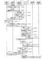
Next, the processing procedure of the message verification system according to the fourth embodiment will be described with reference to FIG. FIG. 13 is a sequence diagram illustrating a processing procedure according to the fourth embodiment.
同図に示すように、発信者認証装置70は、図4に示した実施例1と同様の手順を経て発信者を認証する(ステップS1301〜S1304)。その結果、発信者の認証が失敗すれば、その旨を発信者端末1に送信するが、これとは反対に発信者の認証が成功した場合には、発信者認証装置70は、マスター鍵テーブル14に記憶された鍵Kおよび発信者アドレスSから発信者コードTを生成する(ステップS1305)。 As shown in the figure, the
そして、発信者認証装置70は、認証応答として、生成した発信者コードTを発信者端末1に対して送信する(ステップS1306)。これによって、発信者コードTが有効である限り、発信者は発信者コードTを用いてメールを発信することとなる。 Then, the
すなわち、メールの発信に際して、発信者端末1では、メールの着信者が有する着信者アドレスRの文字列を引数とし、発信者コードTを鍵とする鍵付きハッシュ関数の値を求め、この値の下位30ビットをBASE32符号化によって6文字の文字列に変換することで署名データD(R,T)を生成する(ステップS1307)。 That is, at the time of outgoing mail, the
さらに、発信者端末1は、着信者の着信者アドレスRにおける「ユーザ名」および「ドメイン名」と「署名データ」とを「/」で連結し、さらに、これにリメールサーバ80の「ドメイン名」を「@」を介して結合することで宛先アドレスを新たに生成し、これをTOフィールドに書き込んでメールを発信者メールサーバ6経由でリメールサーバ80に送信する(ステップS1308)。 Further, the
かかるメールを受信したリメールサーバ80では、マスター鍵テーブル84に記憶されたマスター鍵Km、メールの発信元である発信者アドレスSを引数とする演算処理を実行して検証コードVを生成する(ステップS1309)。さらに、リメールサーバ80は、ステップS1309で生成した検証コードVで署名された検証用署名データD(R,V)を生成し(ステップS1310)、さらに、メールの宛先アドレスに含まれる署名データD(R,T)とステップS1310で生成した検証用署名データD(R,V)とが一致するか否かを判定して、発信者コードTの有効性を検証する(ステップS1311)。 In the
この検証の結果、両者が一致しなければ、メールの廃棄等を実行するが、これとは反対に両者が一致する場合には、リメールサーバ80は、発信者端末1から受信したメールを着信者メールサーバ7経由で着信者端末5に転送する(ステップS1312)。具体的には、着信者の着信者アドレスRをTOフィールドに書き込むとともに、発信者の発信者アドレスSにおける「ユーザ名」および「ドメイン名」を「/」で連結し、さらに、これにメール転送サーバ90の「ドメイン名」を「@」を介して結合することでメール転送先アドレスを新たに生成し、これをFROMフィールドに書き込んでメールを転送する。 As a result of the verification, if the two do not match, the mail is discarded or the like. On the contrary, if both match, the
これに対して、メール転送サーバ90は、メールに対する返信メールを着信者端末5から着信者メールサーバ7を介して受信すると(ステップS1313)、発信者認証装置70による発信者コードTの生成と同様の手順で、返信メールの宛先である発信者アドレスSおよびマスター鍵Kmを用いて発信者コードTを生成する(ステップS1314)。 On the other hand, when the
さらに、メール転送サーバ90は、発信者端末1による署名データD(R,T)の生成と同様の手順で、返信メールの発信元である着信者アドレスRおよびステップS1314で生成した発信者コードTを用いて署名データD(R,T)を生成する(ステップS1315)。 Further, the
そして、メール転送サーバ90は、着信者端末5から受信した返信メールを発信者メールサーバ6経由で発信者端末1に転送する(ステップS1316)。具体的には、発信者の発信者アドレスSをTOフィールドに書き込むとともに、着信者の着信者アドレスRにおける「ユーザ名」および「ドメイン名」と「署名データ」とを「/」で連結し、さらに、これにリメールサーバ80の「ドメイン名」を「@」を介して結合することでリメール先アドレスを新たに生成し、これをFROMフィールドに書き込んで返信メールを転送する。なお、発信者が返信メールに対して更なる返信メールを送信した場合には、上記のステップS1308から処理が繰り返される。 Then, the
[実施例4の効果等]
上述してきたように、実施例4によれば、いわゆるメールサービスにおいても、発信者のなりすましによる不正なメール発信を防止することが可能になる。さらに、メッセージの検証を発信者メールサーバ6ではなく、経路中のリメールサーバ80で実行することもできる。[Effects of Example 4 and the like]
As described above, according to the fourth embodiment, even in a so-called mail service, it is possible to prevent unauthorized mail transmission due to spoofing of the caller. Further, the message verification can be executed not by the sender mail server 6 but by the
また、実施例4によれば、メール転送サーバ90で署名コードを含んだ発信元アドレスを作成するので、発信者が返信メールに対してさらに返信しようとする場合に、署名データを含んだ宛先アドレスを再び生成する必要はなく、通常のメール返信処理を発信者が実行するだけで、署名付きのメールを返信することが可能になる。 Further, according to the fourth embodiment, the
さて、これまで本発明の実施例について説明したが、本発明は上述した実施例以外にも、特許請求の範囲に記載した技術的思想の範囲内において種々の異なる形態にて実施されてよいものである。そこで、実施例5として種々の異なる実施例を説明する。 Although the embodiments of the present invention have been described above, the present invention may be implemented in various different forms within the scope of the technical idea described in the claims other than the embodiments described above. It is. Accordingly, various different embodiments will be described as a fifth embodiment.
例えば、上記した実施例では、インスタントメッセージやIP電話、電子メールなどのメッセージサービスに本発明を適用した場合を説明したが、本発明はこれに限定されるものではなく、これらと同様に発信者アドレスを伴ったメッセージを処理するサービスであれば、本発明を同様に適用することができる。 For example, in the above-described embodiment, the case where the present invention is applied to a message service such as an instant message, an IP phone, and an e-mail has been described. However, the present invention is not limited to this, and a caller is similarly provided. The present invention can be similarly applied to any service that processes a message with an address.
また、上記した実施例では、発信者コードで署名された署名データを発信者から受け付けて検証を行う場合を説明したが、本発明はこれに限定されるものではなく、発信者コードそのものを利用者から受け付け、発信者コードの一致不一致によって検証を行うようにしてもよい。この場合でも、ユーザ名やパスワードではなく、発信者アドレスに起因する発信者コードを利用してメッセージ検証を行うので、発信者のなりすましによる不正なメッセージの発信を防止することが可能になる。 In the above-described embodiment, the case where the signature data signed with the sender code is received from the sender and verified is described. However, the present invention is not limited to this, and the sender code itself is used. May be received from the sender and verified based on the match / mismatch of the sender code. Even in this case, since message verification is performed using a caller code originating from a caller address instead of a user name or a password, it is possible to prevent an unauthorized message from being sent due to caller impersonation.
また、上記した実施例では、有効条件も関係付けて発信者コードを生成する場合を説明したが、本発明はこれに限定されるものではなく、少なくとも発信者アドレスおよび鍵を引数として発信者コードを生成するものであれば、他の条件を選択的に付加若しくは削除する場合であっても、本発明を同様に適用することができる。 Further, in the above-described embodiment, the case where the sender code is generated with the validity condition related is described, but the present invention is not limited to this, and at least the sender address and the key as arguments are the sender code. The present invention can be similarly applied even when other conditions are selectively added or deleted.
また、上記した実施例において説明した各処理のうち、自動的におこなわれるものとして説明した処理の全部または一部を手動的におこなうこともでき、あるいは、手動的におこなわれるものとして説明した処理の全部または一部を公知の方法で自動的におこなうこともできる。この他、上記文書中や図面中で示した処理手順、制御手順、具体的名称、各種のデータやパラメータを含む情報(特に、有効条件に関する情報)については、特記する場合を除いて任意に変更することができる。 In addition, among the processes described in the above embodiments, all or a part of the processes described as being automatically performed can be manually performed, or the processes described as being manually performed All or a part of the above can be automatically performed by a known method. In addition, processing procedures, control procedures, specific names, and information including various data and parameters (especially information related to effective conditions) shown in the above documents and drawings are arbitrarily changed unless otherwise specified. can do.
また、上記の実施例で図示した各装置(発信者認証装置、メッセージ受信装置、リメールサーバ、メール転送サーバなど)の各構成要素は機能概念的なものであり、必ずしも物理的に図示の如く構成されていることを要しない。すなわち、各装置の分散・統合の具体的形態は図示のものに限られず、その全部または一部を、各種の負荷や使用状況などに応じて、任意の単位で機能的または物理的に分散・統合して構成することができる。さらに、各装置にて行なわれる各処理機能は、その全部または任意の一部が、CPUおよび当該CPUにて解析実行されるプログラムにて実現され、あるいは、ワイヤードロジックによるハードウェアとして実現され得る。 In addition, each component of each device (such as a caller authentication device, a message receiving device, a re-mail server, and a mail transfer server) illustrated in the above embodiments is functionally conceptual and is not necessarily physically illustrated as illustrated. It doesn't need to be configured. In other words, the specific form of distribution / integration of each device is not limited to that shown in the figure, and all or a part thereof may be functionally or physically distributed or arbitrarily distributed in arbitrary units according to various loads or usage conditions. Can be integrated and configured. Further, all or any part of each processing function performed in each device may be realized by a CPU and a program analyzed and executed by the CPU, or may be realized as hardware by wired logic.
なお、上記の実施例では、本発明を実現する各装置(発信者認証装置、メッセージ受信装置、リメールサーバ、メール転送サーバなど)を機能面から説明したが、各装置の各機能はパーソナルコンピュータやワークステーションなどのコンピュータにプログラムを実行させることによって実現することもできる。すなわち、本実施例で説明した各種の処理手順は、あらかじめ用意されたプログラムをコンピュータに実行することによって実現することができる。そして、これらのプログラムは、インターネットなどのネットワークを介して配布することができる。さらに、これらのプログラムは、ハードディスク、フレキシブルディスク(FD)、CD−ROM、MO、DVDなどのコンピュータで読み取り可能な記録媒体に記録され、コンピュータによって記録媒体から読み出されることによって実行することもできる。つまり、例を挙げれば、実施例1に示したような発信者認証装置10用プログラム、メッセージ受信装置20用プログラムおよび発信者端末1用プログラムを格納したCD−ROM(装置ごとに別個のCD−ROMであってもよい)を配布し、このCD−ROMに格納されたプログラムを各コンピュータが読み出して実行するようにしてもよい。 In the above embodiment, each device (sender authentication device, message receiving device, re-mail server, mail transfer server, etc.) that implements the present invention has been described in terms of functions. However, each function of each device is a personal computer. It can also be realized by causing a computer such as a workstation to execute the program. That is, the various processing procedures described in the present embodiment can be realized by executing a program prepared in advance on a computer. These programs can be distributed via a network such as the Internet. Further, these programs can be recorded on a computer-readable recording medium such as a hard disk, a flexible disk (FD), a CD-ROM, an MO, and a DVD, and can be executed by being read from the recording medium by the computer. That is, for example, a CD-ROM (a separate CD-ROM for each device) storing the program for the
以上のように、本発明に係るメッセージ検証システム、メッセージ検証方法およびメッセージ検証プログラムは、利用者端末から発信されたメッセージが当該メッセージのサービスを利用し得る正当な利用者から発信されたものであるかを検証する場合に有用であり、特に、発信者のなりすましによる不正なメッセージの発信を防止するためのメッセージ検証を高速かつ軽負荷で実現することに適する。 As described above, the message verification system, the message verification method, and the message verification program according to the present invention are those in which a message transmitted from a user terminal is transmitted from a legitimate user who can use the service of the message. In particular, it is suitable for realizing message verification for preventing unauthorized message transmission by spoofing of the sender at high speed and with a light load.
1 発信者端末
2 IP網
3 インターネット
4 LAN
10 発信者認証装置
11 認証通信部
12 ユーザテーブル
13 発信者認証部
14 マスター鍵テーブル
15 発信者コード生成部
20 メッセージ受信装置
21 メッセージ受信部
22 メッセージ処理部
23 有効条件判定部
24 マスター鍵テーブル
25 検証コード生成部
26 コード検証部1
DESCRIPTION OF
Claims (21)
Translated fromJapanese前記正当な利用者であることを証明する発信者コードを、所定の鍵および前記利用者の発信者アドレスを引数とする演算処理を実行して生成する発信者コード生成手段と、
前記利用者端末から前記メッセージとともに前記発信者コード生成手段によって生成された発信者コードを受信し、当該メッセージの発信者アドレスおよび前記所定の鍵を用いて前記発信者コードの有効性を検証する検証手段と、
を備えたことを特徴とするメッセージ検証システム。A message verification system for verifying whether a message transmitted from a user terminal is transmitted from a legitimate user who can use the service of the message,
A caller code generating means for generating a caller code for certifying that the user is a legitimate user by executing a calculation process using a predetermined key and the caller address of the user as an argument;
Verification that receives the caller code generated by the caller code generation means together with the message from the user terminal, and verifies the validity of the caller code using the caller address of the message and the predetermined key Means,
A message verification system comprising:
前記正当な利用者であることを証明する発信者コードを、所定の鍵および前記利用者の発信者アドレスを引数とする演算処理を実行して生成する発信者コード生成手段と、
前記利用者端末から前記メッセージとともに、前記発信者コード生成手段によって生成された発信者コードで署名された署名データを受信し、前記メッセージの発信者アドレスおよび前記所定の鍵を用いて前記発信者コードの有効性を検証する検証手段と、
を備えたことを特徴とするメッセージ検証システム。A message verification system for verifying whether a message transmitted from a user terminal is transmitted from a legitimate user who can use the service of the message,
A caller code generating means for generating a caller code for certifying that the user is a legitimate user by executing a calculation process using a predetermined key and the caller address of the user as an argument;
The signature data signed with the caller code generated by the caller code generation means is received together with the message from the user terminal, and the caller code using the caller address of the message and the predetermined key Verification means for verifying the effectiveness of
A message verification system comprising:
前記利用者端末から受信したメッセージの発信者アドレスおよび前記所定の鍵を引数として前記発信者コードの生成と同様の演算処理を実行して、前記発信者コードの有効性を検証する検証コードを生成する検証コード生成手段と、
前記検証コード生成手段によって生成された検証コードで署名された検証用署名データを生成する検証用署名データ生成手段と、
前記利用者端末から受信した署名データと前記検証用署名データ生成手段によって生成された検証用署名データとが一致するか否かを判定して、前記発信者コードの有効性を検証するコード検証手段と、
を備えたことを特徴とする請求項2に記載のメッセージ検証システム。The verification means includes
A verification code for verifying the validity of the caller code is generated by performing the same arithmetic processing as the caller code generation using the caller address of the message received from the user terminal and the predetermined key as arguments. Verification code generation means for
Verification signature data generation means for generating verification signature data signed with the verification code generated by the verification code generation means;
Code verification means for determining whether the signature data received from the user terminal matches the verification signature data generated by the verification signature data generation means and verifying the validity of the sender code When,
The message verification system according to claim 2, further comprising:
前記利用者に付与された発信条件を前記メッセージとともに前記利用者端末から受信し、前記メッセージの発信が当該発信条件を満たすか否かを判定する発信条件判定手段と、
を備え、
前記検証コード生成手段は、前記発信条件判定手段によって前記メッセージの発信が前記発信条件を満たすと判定された場合にのみ、当該発信条件をさらに引数とする演算処理を実行して前記検証コードを生成することを特徴とする請求項4または5に記載のメッセージ検証システム。Along with a caller code generated by the caller code generation means, a granting means for giving the user a call condition used to generate the caller code;
A transmission condition determination means for receiving the transmission condition given to the user together with the message from the user terminal, and determining whether the transmission of the message satisfies the transmission condition;
With
The verification code generation unit generates the verification code by executing a calculation process using the transmission condition as an argument only when the transmission condition determination unit determines that the transmission of the message satisfies the transmission condition. The message verification system according to claim 4 or 5, wherein
前記検証コード生成手段は、前記発信条件取得手段によって取得した発信条件をさらに引数とする演算処理を実行して前記検証コードを生成することを特徴とする請求項4または5に記載のメッセージ検証システム。When receiving the message from the user terminal, comprising a transmission condition acquisition means for acquiring a transmission condition to be satisfied by the transmission of the message based on the reception status of the message,
The message verification system according to claim 4 or 5, wherein the verification code generation unit generates the verification code by executing a calculation process using the transmission condition acquired by the transmission condition acquisition unit as an argument. .
前記複数のサーバは、前記所定の鍵をそれぞれ有し、前記検証コードをそれぞれ生成することを特徴とする請求項4〜10のいずれか一つに記載のメッセージ検証システム。A plurality of servers connected to the user terminal via a network each include the verification code generation means,
The message verification system according to claim 4, wherein each of the plurality of servers has the predetermined key and generates the verification code.
当該リメールサーバは、前記発信者コードの有効性が認められた場合に、前記メールの宛先アドレスを前記着信者アドレスに置換して転送することを特徴とする請求項2〜11のいずれか一つに記載のメッセージ検証システム。A re-mail server that receives a mail at a destination address composed of the recipient address of the recipient who receives the message and the signature data comprises the verification means,
12. The re-mail server, when the validity of the caller code is recognized, transfers the mail by replacing the destination address of the mail with the callee address. The message verification system described in 1.
当該メール転送サーバは、前記発信者コードを再生成した後に、当該発信者コードを用いて前記署名データを再生成し、前記返信メールの発信元を前記着信者アドレスおよび署名データからなるアドレスに置換して転送することを特徴とする請求項12に記載のメッセージ検証システム。A mail transfer server that receives a reply mail to the mail transferred by the re-mail server;
The mail transfer server regenerates the caller code, regenerates the signature data using the caller code, and replaces the sender of the reply mail with an address composed of the callee address and signature data The message verification system according to claim 12, wherein the message verification system transfers the message.
前記正当な利用者であることを証明する発信者コードを、所定の鍵および前記利用者の発信者アドレスを引数とする演算処理を実行して生成する発信者コード生成工程と、
前記利用者端末から前記メッセージとともに前記発信者コード生成工程によって生成された発信者コードを受信し、当該メッセージの発信者アドレスおよび前記所定の鍵を用いて前記発信者コードの有効性を検証する検証工程と、
を含んだことを特徴とするメッセージ検証方法。A message verification method for verifying whether a message transmitted from a user terminal is transmitted from a legitimate user who can use the service of the message,
A caller code generating step for generating a caller code for certifying that the user is a legitimate user by executing a calculation process using a predetermined key and the caller address of the user as an argument;
Verification that receives the caller code generated by the caller code generation step together with the message from the user terminal, and verifies the validity of the caller code using the caller address of the message and the predetermined key Process,
The message verification method characterized by including.
前記正当な利用者であることを証明する発信者コードを、所定の鍵および前記利用者の発信者アドレスを引数とする演算処理を実行して生成する発信者コード生成工程と、
前記利用者端末から前記メッセージとともに、前記発信者コード生成工程によって生成された発信者コードで署名された署名データを受信し、前記メッセージの発信者アドレスおよび前記所定の鍵を用いて前記発信者コードの有効性を検証する検証工程と、
を含んだことを特徴とするメッセージ検証方法。A message verification method for verifying whether a message transmitted from a user terminal is transmitted from a legitimate user who can use the service of the message,
A caller code generating step for generating a caller code for certifying that the user is a legitimate user by executing a calculation process using a predetermined key and the caller address of the user as an argument;
The signature data signed by the caller code generated by the caller code generation step is received together with the message from the user terminal, and the caller code using the caller address of the message and the predetermined key A verification process to verify the effectiveness of
The message verification method characterized by including.
前記利用者端末から受信したメッセージの発信者アドレスおよび前記所定の鍵を引数として前記発信者コードの生成と同様の演算処理を実行して、前記発信者コードの有効性を検証する検証コードを生成する検証コード生成工程と、
前記検証コード生成工程によって生成された検証コードで署名された検証用署名データを生成する検証用署名データ生成工程と、
前記利用者端末から受信した署名データと前記検証用署名データ生成工程によって生成された検証用署名データとが一致するか否かを判定して、前記発信者コードの有効性を検証するコード検証工程と、
を含んだことを特徴とする請求項15に記載のメッセージ検証方法。The verification step includes
A verification code for verifying the validity of the caller code is generated by performing the same arithmetic processing as the caller code generation using the caller address of the message received from the user terminal and the predetermined key as arguments. A verification code generation process,
A verification signature data generation step for generating verification signature data signed with the verification code generated by the verification code generation step;
A code verification step of determining whether the signature data received from the user terminal matches the verification signature data generated by the verification signature data generation step and verifying the validity of the sender code When,
The message verification method according to claim 15, further comprising:
前記正当な利用者であることを証明する発信者コードを、所定の鍵および前記利用者の発信者アドレスを引数とする演算処理を実行して生成する発信者コード生成手順と、
前記利用者端末から前記メッセージとともに前記発信者コード生成手順によって生成された発信者コードを受信し、当該メッセージの発信者アドレスおよび前記所定の鍵を用いて前記発信者コードの有効性を検証する検証手順と、
をコンピュータに実行させることを特徴とするメッセージ検証プログラム。A message verification program for causing a computer to execute a method of verifying whether a message transmitted from a user terminal is transmitted from a legitimate user who can use the service of the message,
A caller code generation procedure for generating a caller code for certifying that the user is a legitimate user by executing a calculation process using a predetermined key and the caller address of the user as an argument;
Verification that receives the caller code generated by the caller code generation procedure together with the message from the user terminal, and verifies the validity of the caller code using the caller address of the message and the predetermined key Procedure and
A message verification program for causing a computer to execute
前記正当な利用者であることを証明する発信者コードを、所定の鍵および前記利用者の発信者アドレスを引数とする演算処理を実行して生成する発信者コード生成手順と、
前記利用者端末から前記メッセージとともに、前記発信者コード生成手順によって生成された発信者コードで署名された署名データを受信し、前記メッセージの発信者アドレスおよび前記所定の鍵を用いて前記発信者コードの有効性を検証する検証手順と、
をコンピュータに実行させることを特徴とするメッセージ検証プログラム。A message verification program for causing a computer to execute a method of verifying whether a message transmitted from a user terminal is transmitted from a legitimate user who can use the service of the message,
A caller code generation procedure for generating a caller code for certifying that the user is a legitimate user by executing a calculation process using a predetermined key and the caller address of the user as an argument;
The signature data signed by the caller code generated by the caller code generation procedure is received together with the message from the user terminal, and the caller code using the caller address of the message and the predetermined key Verification procedures to verify the effectiveness of
A message verification program for causing a computer to execute
前記利用者端末から受信したメッセージの発信者アドレスおよび前記所定の鍵を引数として前記発信者コードの生成と同様の演算処理を実行して、前記発信者コードの有効性を検証する検証コードを生成する検証コード生成手順と、
前記検証コード生成手順によって生成された検証コードで署名された検証用署名データを生成する検証用署名データ生成手順と、
前記利用者端末から受信した署名データと前記検証用署名データ生成手順によって生成された検証用署名データとが一致するか否かを判定して、前記発信者コードの有効性を検証するコード検証手順と、
をコンピュータに実行させることを特徴とする請求項19に記載のメッセージ検証プログラム。The verification procedure includes:
A verification code for verifying the validity of the caller code is generated by performing the same arithmetic processing as the caller code generation using the caller address of the message received from the user terminal and the predetermined key as arguments. Verification code generation procedure to
A verification signature data generation procedure for generating verification signature data signed with the verification code generated by the verification code generation procedure;
Code verification procedure for determining whether the signature data received from the user terminal matches the verification signature data generated by the verification signature data generation procedure and verifying the validity of the sender code When,
The message verification program according to claim 19, wherein the message is executed by a computer.
The caller code generation procedure and the verification code generation procedure execute an arithmetic process using a call condition that should be satisfied by the call transmission in addition to the predetermined key and the caller address, and the caller code or 21. The message verification program according to claim 20, wherein a verification code is generated.
Priority Applications (1)
| Application Number | Priority Date | Filing Date | Title |
|---|---|---|---|
| JP2003375572AJP2005142719A (en) | 2003-11-05 | 2003-11-05 | Message verification system, message verification method, and message verification program |
Applications Claiming Priority (1)
| Application Number | Priority Date | Filing Date | Title |
|---|---|---|---|
| JP2003375572AJP2005142719A (en) | 2003-11-05 | 2003-11-05 | Message verification system, message verification method, and message verification program |
Publications (1)
| Publication Number | Publication Date |
|---|---|
| JP2005142719Atrue JP2005142719A (en) | 2005-06-02 |
Family
ID=34686908
Family Applications (1)
| Application Number | Title | Priority Date | Filing Date |
|---|---|---|---|
| JP2003375572APendingJP2005142719A (en) | 2003-11-05 | 2003-11-05 | Message verification system, message verification method, and message verification program |
Country Status (1)
| Country | Link |
|---|---|
| JP (1) | JP2005142719A (en) |
Cited By (3)
| Publication number | Priority date | Publication date | Assignee | Title |
|---|---|---|---|---|
| JP2010537292A (en)* | 2007-08-21 | 2010-12-02 | エンドレス ウント ハウザー コンダクタ ゲゼルシャフト フューア メス‐ ウント レーゲルテヒニック エムベーハー ウント コンパニー コマンディートゲゼルシャフト | Method for compatibility checking of measuring systems with measuring transducers and sensors |
| KR101425320B1 (en)* | 2013-04-24 | 2014-08-01 | 에스케이씨앤씨 주식회사 | Trusted Message Operation Method and System using the same |
| CN114422140A (en)* | 2021-12-27 | 2022-04-29 | 微位(深圳)网络科技有限公司 | Message time verification method, device, equipment and medium |
- 2003
- 2003-11-05JPJP2003375572Apatent/JP2005142719A/enactivePending
Cited By (5)
| Publication number | Priority date | Publication date | Assignee | Title |
|---|---|---|---|---|
| JP2010537292A (en)* | 2007-08-21 | 2010-12-02 | エンドレス ウント ハウザー コンダクタ ゲゼルシャフト フューア メス‐ ウント レーゲルテヒニック エムベーハー ウント コンパニー コマンディートゲゼルシャフト | Method for compatibility checking of measuring systems with measuring transducers and sensors |
| KR101425320B1 (en)* | 2013-04-24 | 2014-08-01 | 에스케이씨앤씨 주식회사 | Trusted Message Operation Method and System using the same |
| WO2014175671A1 (en)* | 2013-04-24 | 2014-10-30 | 에스케이씨앤씨 주식회사 | Method for operating reliable message and system for same |
| CN114422140A (en)* | 2021-12-27 | 2022-04-29 | 微位(深圳)网络科技有限公司 | Message time verification method, device, equipment and medium |
| CN114422140B (en)* | 2021-12-27 | 2024-03-12 | 微位(深圳)网络科技有限公司 | Message time verification method, device, equipment and medium |
Similar Documents
| Publication | Publication Date | Title |
|---|---|---|
| JP5047291B2 (en) | Method and system for providing authentication services to Internet users | |
| US9509681B2 (en) | Secure instant messaging system | |
| US8214649B2 (en) | System and method for secure communications between at least one user device and a network entity | |
| US7039713B1 (en) | System and method of user authentication for network communication through a policy agent | |
| JP5291725B2 (en) | IP address delegation | |
| US7721093B2 (en) | Authenticated exchange of public information using electronic mail | |
| KR101219862B1 (en) | System and method for establishing that a server and a correspondent have compatible secure email | |
| JP2008529326A (en) | Method and system for electronic message management and filtering using cryptographic techniques | |
| CN107517194B (en) | Return source authentication method and device of content distribution network | |
| CN103401872B (en) | The method prevented and detect man-in-the-middle attack based on RDP improved protocol | |
| JP4367546B2 (en) | Mail relay device | |
| CN114386086A (en) | Blacklist data sharing method and obtaining method | |
| CN101795301A (en) | Key complaint method for enhancement of authenticity guarantee of source address | |
| JP2004274134A (en) | Communication method and communication system, server and client using this communication method | |
| Schulz et al. | d 2 Deleting Diaspora: Practical attacks for profile discovery and deletion | |
| JP2005142719A (en) | Message verification system, message verification method, and message verification program | |
| JP4137769B2 (en) | Communication system, communication method, and communication program | |
| KR101204648B1 (en) | Method for exchanging key between mobile communication network and wireless communication network | |
| JP3908722B2 (en) | Message delivery system, message delivery method, and message delivery program | |
| Roy et al. | Practical {Privacy-Preserving} Authentication for {SSH} | |
| Mueller | Let’s attest! Multi-modal certificate exchange for the web of trust | |
| Pérez et al. | Interoperable Symmetric Message Franking | |
| Breuch | Web Key Directory and other key exchange methods for OpenPGP | |
| Wolf | A certificate-poisoning-resistant protocol for the synchronization of Web of Trust networks | |
| Wolf Iszaevich | A certificate-poisoning-resistant protocol for the synchronization of web of trust networks |
Legal Events
| Date | Code | Title | Description |
|---|---|---|---|
| A621 | Written request for application examination | Free format text:JAPANESE INTERMEDIATE CODE: A621 Effective date:20050513 | |
| A131 | Notification of reasons for refusal | Free format text:JAPANESE INTERMEDIATE CODE: A131 Effective date:20080617 | |
| A02 | Decision of refusal | Free format text:JAPANESE INTERMEDIATE CODE: A02 Effective date:20081021 |