JP2005138686A - Vehicle sun visor - Google Patents
Vehicle sun visorDownload PDFInfo
- Publication number
- JP2005138686A JP2005138686AJP2003376243AJP2003376243AJP2005138686AJP 2005138686 AJP2005138686 AJP 2005138686AJP 2003376243 AJP2003376243 AJP 2003376243AJP 2003376243 AJP2003376243 AJP 2003376243AJP 2005138686 AJP2005138686 AJP 2005138686A
- Authority
- JP
- Japan
- Prior art keywords
- sun visor
- lid
- vehicle
- light
- visor body
- Prior art date
- Legal status (The legal status is an assumption and is not a legal conclusion. Google has not performed a legal analysis and makes no representation as to the accuracy of the status listed.)
- Pending
Links
- 239000005357flat glassSubstances0.000claimsdescription3
- 238000005286illuminationMethods0.000abstractdescription18
- 230000002093peripheral effectEffects0.000description6
- 238000010586diagramMethods0.000description5
- 230000009471actionEffects0.000description2
- 239000004020conductorSubstances0.000description2
- NIXOWILDQLNWCW-UHFFFAOYSA-Nacrylic acid groupChemical groupC(C=C)(=O)ONIXOWILDQLNWCW-UHFFFAOYSA-N0.000description1
- 230000000903blocking effectEffects0.000description1
- 230000008859changeEffects0.000description1
- 230000007423decreaseEffects0.000description1
- 239000000463materialSubstances0.000description1
- 238000000034methodMethods0.000description1
- 230000004048modificationEffects0.000description1
- 238000012986modificationMethods0.000description1
- 229920000515polycarbonatePolymers0.000description1
- 239000004417polycarbonateSubstances0.000description1
- 230000008569processEffects0.000description1
Images


Classifications
- B—PERFORMING OPERATIONS; TRANSPORTING
- B60—VEHICLES IN GENERAL
- B60J—WINDOWS, WINDSCREENS, NON-FIXED ROOFS, DOORS, OR SIMILAR DEVICES FOR VEHICLES; REMOVABLE EXTERNAL PROTECTIVE COVERINGS SPECIALLY ADAPTED FOR VEHICLES
- B60J3/00—Antiglare equipment associated with windows or windscreens; Sun visors for vehicles
- B60J3/02—Antiglare equipment associated with windows or windscreens; Sun visors for vehicles adjustable in position
- B60J3/0204—Sun visors
- B60J3/0278—Sun visors structure of the body
- B60J3/0282—Sun visors structure of the body specially adapted for a courtesy mirror
Landscapes
- Engineering & Computer Science (AREA)
- Mechanical Engineering (AREA)
- Arrangements Of Lighting Devices For Vehicle Interiors, Mounting And Supporting Thereof, Circuits Therefore (AREA)
- Mirrors, Picture Frames, Photograph Stands, And Related Fastening Devices (AREA)
Abstract
Translated fromJapaneseDescription
Translated fromJapanese本発明は、サンバイザ本体の表面に蓋付のミラーが装着されており、前記蓋が開かれると、その蓋に隠れていた照明具が現れて点灯する構成の車両用サンバイザに関する。 The present invention relates to a vehicle sun visor having a configuration in which a mirror with a lid is mounted on the surface of a sun visor body, and when the lid is opened, a lighting device hidden in the lid appears and lights up.
これに関連する従来の車両用サンバイザが特許文献1に記載されている。
前記車両用サンバイザは、車室内への陽光を遮るサンバイザ本体を備えている。サンバイザ本体は、図6に示すように、表面中央に角形のホルダー94が取付けられており、そのホルダー94にミラー95と照明具96とが収納固定されている。ホルダー94には回転蓋94hが取付けられており、その回転蓋94hが開かれた状態でミラー95と照明具96とが現れるようになっている。前記回転蓋94hの回転中心部分にはスイッチ(図示省略)が設けられており、その回転蓋94hが開かれることでスイッチがオンし、回転蓋94hが閉じられることでスイッチがオフするように構成されている。そして、前記スイッチがオンすることで、照明具96に電力が供給されてその照明具96が点灯する。即ち、回転蓋94hを開けてミラー95を使用するときに、自動的に照明具96が点灯し、室内が暗いときでもミラー95を使用できるようになる。A conventional vehicle sun visor related to this is described in Patent Document 1.
The vehicle sun visor includes a sun visor body that blocks sunlight into the vehicle interior. As shown in FIG. 6, the sun visor body has a
上記した車両用サンバイザによると、ミラー95を使用しないとき、即ち、回転蓋94hが閉じられているときには、前記スイッチがオフするため照明具96は点灯しない。このため、ミラーを使用する際の照明以外の目的でその照明具96を使用することはできない。
仮に照明具96を他の用途に使用したい場合には、その都度、回転蓋94hを開かなければならず、使い勝手が良くない。
本発明は、上記問題点を解決するためになされたものであり、本発明の技術的課題は、ミラーの蓋を閉じたままでそのミラーの照明具を他の用途に使用できるようにして車両用サンバイザの使い勝手を向上させることである。According to the vehicle sun visor described above, when the
If it is desired to use the
The present invention has been made to solve the above-described problems, and a technical problem of the present invention is that the mirror illumination device can be used for other applications while the mirror cover is closed. It is to improve the usability of the sun visor.
上記した課題は、各請求項の発明によって解決される。
請求項1の発明は、サンバイザ本体の表面に蓋付のミラーが装着されており、前記蓋が開かれると、その蓋に隠れていた照明具が現れて点灯する構成の車両用サンバイザであって、前記蓋が閉じられている状態で前記照明具を点灯させることが可能な補助点灯手段と、前記蓋が閉じられている状態で前記照明具が前記サンバイザ本体の表面を照らせるように、その照明具の光を前記蓋の外に漏らすことができる光漏出手段とを有することを特徴とする。The above-described problems are solved by the inventions of the claims.
The invention of claim 1 is a vehicle sun visor having a configuration in which a mirror with a lid is attached to the surface of a sun visor body, and when the lid is opened, a lighting fixture hidden in the lid appears and lights up. Auxiliary lighting means capable of lighting the lighting device in a state in which the lid is closed, and lighting so that the lighting device can illuminate the surface of the sun visor body in the state in which the lid is closed Light leakage means capable of leaking the light of the tool out of the lid.
本発明によると、ミラーを使用しないとき、即ち、そのミラーの蓋が閉じられているときでも、補助点灯手段によりミラー用の照明具を点灯させることができる。このとき、前記照明具の光は光漏出手段の働きで蓋の外に漏れ、サンバイザ本体の表面を照らすようになる。このため、ミラー用の照明具を、例えば、サンバイザ本体のカードホルダや小物入れの照明具として兼用できるようになる。 According to the present invention, even when the mirror is not used, that is, when the lid of the mirror is closed, the mirror lighting device can be turned on by the auxiliary lighting means. At this time, the light from the illuminator leaks out of the lid by the light leakage means, and illuminates the surface of the sun visor body. For this reason, the illumination tool for mirrors can be used as, for example, a card holder for a sun visor body or an illumination tool for an accessory case.
請求項2の発明によると、補助点灯手段は、サンバイザ本体を車両の天井に沿う格納位置からその車両の窓ガラス側の遮光位置まで回転させたときに動作する回転スイッチと、前記回転スイッチが動作した時から所定時間だけ照明具に電力を供給するタイマー回路とを有することを特徴とする。
ここで、スイッチとは、一方の導電体と他方の導電体とを電気的に接続したり、その接続を解除可能な構造のものを全て含むものとする。
本発明によると、サンバイザ本体を格納位置から遮光位置まで下ろすことで回転スイッチが動作し、照明具が自動的に点灯するようになる。即ち、サンバイザ本体を遮光位置まで下ろすだけで、ミラー用の照明具をサンバイザ本体のカードホルダや小物入れの照明具として使用できるようになる。さらに、タイマー回路の働きで、所定時間経過後は照明具に対する電力の供給が停止されるため、消灯操作が不要になる。According to the second aspect of the present invention, the auxiliary lighting means operates when the sun visor main body is rotated from the storage position along the vehicle ceiling to the light shielding position on the window glass side of the vehicle, and the rotation switch operates. And a timer circuit for supplying electric power to the illuminator for a predetermined period of time.
Here, the switch includes all the structures that can electrically connect one conductor and the other conductor or can release the connection.
According to the present invention, the rotary switch is operated by lowering the sun visor body from the storage position to the light shielding position, and the lighting device is automatically turned on. That is, the mirror illuminator can be used as a card holder for the sun visor body or an illuminator for small items by simply lowering the sun visor body to the light shielding position. Furthermore, since the timer circuit functions to stop the power supply to the illuminator after a predetermined time has elapsed, the light-off operation is not necessary.
請求項3の発明によると、光漏出手段は蓋の端縁に形成されたスリットである。このため、光漏出手段を低コストで製作できるようになる。
ここで、光漏出手段は、請求項4に示すように、蓋が閉じられた状態で、その蓋とサンバイザ本体との間に形成される隙間であって良いし、請求項5に示すように、蓋に隠れない位置でサンバイザ本体に形成されたスリットであっても良い。
また、光漏出手段は、請求項6に示すように、蓋及び/又はサンバイザ本体に形成された透明部であっても良い。According to the invention of claim 3, the light leakage means is a slit formed at the edge of the lid. For this reason, the light leakage means can be manufactured at low cost.
Here, as shown in claim 4, the light leakage means may be a gap formed between the lid and the sun visor body when the lid is closed. The slit may be formed in the sun visor body at a position not hidden by the lid.
Further, the light leakage means may be a transparent portion formed on the lid and / or the sun visor body as shown in claim 6.
本発明によれば、ミラーの蓋を閉じたままでそのミラー用の照明具を、例えば、サンバイザ本体のカードホルダや小物入れの照明具として兼用できるようになる。このため、車両用サンバイザの使い勝手が向上する。 According to the present invention, the mirror illumination device can be used as, for example, a card holder of a sun visor body or an illumination device for an accessory case with the mirror lid closed. For this reason, the usability of the vehicle sun visor is improved.
(実施形態1)
以下、図1から図5に基づいて、本発明の実施形態1に係る車両用サンバイザの説明を行う。ここで、図1は本実施形態に係る車両用サンバイザの全体斜視図、図2は前記車両用サンバイザのミラー及び蓋の部分を表す縦断面図等である。図3は照明具の構成を表す模式図、図4は照明具の電気回路図である。また、図5は車両用サンバイザの変更例を表す部分拡大図等である。(Embodiment 1)
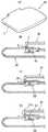
Hereinafter, the vehicle sun visor according to the first embodiment of the present invention will be described with reference to FIGS. 1 to 5. Here, FIG. 1 is an overall perspective view of the vehicle sun visor according to the present embodiment, and FIG. 2 is a longitudinal sectional view showing the mirror and lid portions of the vehicle sun visor. FIG. 3 is a schematic diagram showing the configuration of the lighting fixture, and FIG. 4 is an electric circuit diagram of the lighting fixture. FIG. 5 is a partially enlarged view showing a modification example of the vehicle sun visor.
車両用サンバイザ10は、図1に示すように、車室内に射しこむ太陽光を遮るサンバイザ本体20と、そのサンバイザ本体20を上下回動可能に支持する支軸12とを備えている。支軸12の基端部には支持フランジ13に連結されており、その支持フランジ13が車室天井面Tに固定されている。これによって、サンバイザ本体20は車室天井面Tに沿う格納位置と、窓ガラス側の遮光位置との間で上下回動が可能になる。なお、図1(A)(B)は、サンバイザ本体20を遮光位置まで下ろした状態を表している。 As shown in FIG. 1, the
サンバイザ本体20は、肉厚に形成された周縁部22と、その周縁部22の内側に設けられた比較的肉薄の板状部24とから構成されている。サンバイザ本体20が遮光位置にあるときに乗員と対向する側の面、即ち、サンバイザ本体20の表面には、板状部24の略中央位置に角形のミラー26が取り付けられている。ミラー26は、その端縁が板状部24と一体化された断面鉤形のトリム24tによって押さえられることで、その板状部24に固定されている。また、サンバイザ本体20の表面左下部には、周縁部22と板状部24との境界部分にカードCを保持するカードホルダ28が設けられている。 The
サンバイザ本体20の表面には、周縁部22の上部位置にミラー26の蓋30が上下回動可能な状態で連結されている。蓋30は、図1(B)、図2(A)に示すように、サンバイザ本体20の板状部24に重ねられてミラー26全体を覆う閉位置と、図1(A)に示すように、ミラー26を露出させる開位置との間で上下回動可能に構成されている。開位置では、蓋30はバネ等(図示省略)の弾性力でそのサンバイザ本体20に対してほぼ直角に保持される。
蓋30の厚み寸法は、その蓋30がサンバイザ本体20の板状部24に重ねられた状態で、蓋30の表面31の高さがサンバイザ本体20の周縁部22の高ささとほぼ等しくなるような値に設定されている。On the surface of the
The thickness of the
蓋30の表面31と反対側の面32、即ち、蓋30の内側面32には、図2(A)に示すように、蓋30が閉位置にある状態でミラー26が収納されるミラー用凹部36が形成されている。ここで、図2(A)は、図1(B)のIIA‐IIA矢視断面図を表している。また、蓋30の内側面32には、ミラー用凹部36の幅方向両側に照明具40(後述する)を収納する照明具用凹部38が形成されている。 On the
照明具40は、ミラー26用の照明とカードホルダ28用の照明とを兼用する照明具であり、光源である発光ダイオード42(以下、LED42と呼ぶ)と、LED42の光を所定位置まで導くとともに、その光をほぼ均等に屈折・散乱させる導光板44とから構成されている。
導光板44は、照明具用凹部38に収納される角形の透明板であり、その照明具用凹部38の開口縁に形成された内フランジ38fによって、その導光板44の周縁部分が押さえられている。また、LED42は、蓋30の回動中心に最も近い位置で照明具用凹部38に収納されており、図2(B)に示すように、内フランジ38fの内側に配置されている。なお、LED42は、一般的に一枚の導光板44に対して二個使用されるが、使用個数は適宜変更可能である。ここで、図2(B)は、図1(A)のIIB‐IIB矢視断面図である。The
The
図3(A)(B)は、上記照明具40の導光板44の働きを表す模式図である。
導光板44の表面には、図3(A)に示すように、その導光板44に沿って進む光を交差する方向に屈折させる断面V字形の溝44mが複数本形成されている。溝44mは、LED42からの距離が大きくなるにつれて深く、かつ広く形成されている。ここで、屈折させられる光(屈折光)の量は溝44mの溝面積に比例するため、溝44mが深く、広くなると、光の屈折量が多くなる。一方、光のエネルギーはLED42からの距離の二乗に反比例して減少するため、LED42の近傍ではエネルギーが大きく、LED42から離れた部位ではエネルギーが小さい。FIGS. 3A and 3B are schematic views showing the function of the
As shown in FIG. 3A, a plurality of V-shaped
上記照明具40では、屈折光の量がLED42からの距離に係わらず導光板44全体でほぼ一定となるように、溝44mの位置における光のエネルギーの減少分等を考慮して、その溝44mの深さ、広さが設定されている。導光板44の材料としてはアクリル、ポリカーボネイト等が好適に使用される。
また、上記したように溝44mを形成する代わりに、図3(B)に示すように、導光板44の表面を細かい凹凸のある傾斜面とし、その傾斜面で光を屈折させるようにしても良い。In the
Further, instead of forming the
前述のように、導光板44は蓋30の内側面32に形成された照明具用凹部38に収納されており、その照明具用凹部38の開口縁に形成された内フランジ38fによって押さえれている。このため、蓋30が開かれた状態で、LED42の光は導光板44を介して照明具用凹部38の開口からほぼ均等に放射されて、周囲を照らすようになる。 As described above, the
また、蓋30の幅方向両側面には、図2(C)に示すように、蓋30の長手方向に沿って照明具用凹部38の内部空間と連通するスリット39が形成されている。スリット39は、蓋30が閉じられている状態であっても、導光板44によって屈折させられたLED42の光を外部に漏らして、サンバイザ本体20の表面を照らせるようにするものである。即ち、前記スリット39が本発明の光漏出手段に相当する。ここで、図2(C)は、図1(A)のIIC‐IIC矢視図を表している。
なお、照明具用凹部38の壁面には反射板(図示省略)を貼り付けておくのが好ましい。Further, on both side surfaces in the width direction of the
In addition, it is preferable to affix a reflecting plate (not shown) on the wall surface of the
図4は、照明具40の電気回路を表している。
電気回路の電源としては、車両のバッテリの直流12V電源が使用される。
図示するように、LED42のプラス端子にはサンバイザ本体20の回転スイッチSW1とタイマー回路TMを介して電源回路の+12V端子Pが接続されている。また、サンバイザ本体20の回転スイッチSW1とタイマー回路TMに対して並列に蓋30の回転スイッチSW2が接続されている。LED42のマイナス端子は電源回路のアース端子Gに接続されている。FIG. 4 shows an electric circuit of the
As a power source for the electric circuit, a DC 12V power source for a vehicle battery is used.
As shown in the figure, the + 12V terminal P of the power supply circuit is connected to the plus terminal of the
このため、サンバイザ本体20の回転スイッチSW1がオンするとタイマー回路TMで設定された時間(例えば、10秒間)だけLED42が点灯する。また、タイマー回路TMで設定された時間が経過した後であっても、蓋30の回転スイッチSW2がオンしている間だけLED42は点灯するようになる。
ここで、サンバイザ本体20の回転スイッチSW1は、サンバイザ本体20が遮光位置まで下ろされた状態でオン、格納位置まで上げられる途中でオフするように、構成されている。また、蓋30の回転スイッチSW2は、蓋30が開位置に保持された状態でオン、蓋30が閉位置まで戻される過程でオフするように構成されている。For this reason, when the rotation switch SW1 of the
Here, the rotation switch SW1 of the
次に、本実施形態に係る車両用サンバイザ10の動作を説明する。
例えば、車両の夜間走行中において、サンバイザ本体20のカードホルダ28からハイウエーカードCを取ろうとする場合等は、サンバイザ本体20を格納位置から遮光位置まで下ろす。これによって、サンバイザ本体20の回転スイッチSW1がオンし、タイマー回路TMで設定された時間(例えば、10秒間)だけ照明具40のLED42が点灯する。LED42が点灯すると、LED42の光は導光板44に沿って進み、その導光板44の各々の溝44mによって屈折させられる。各々の溝44mは、屈折光の量がLED42からの距離に係わらず導光板44全体でほぼ一定となるように形成されているため、前記導光板44はほぼ均一に光るようになる。このとき、蓋30は閉位置にあるため、導光板44によって屈折させられた光は、蓋30のスリット39から外に漏れ出て、周囲を照らすようになる。これによって、カードホルダ28の周辺が明るくなり、運転者がハイウエーカードCを取り易くなる。Next, the operation of the
For example, when the highway card C is to be taken from the
ここで、照明具40のLED42はタイマー回路TMによって10秒後に消灯されるため、照明具40を消すための操作も不要であるし、消し忘れなどの問題も生じない。なお、例えば、太陽光を遮光するために、サンバイザ本体20を遮光位置まで下ろした場合にもLED42が点灯するが、LED42はタイマー回路TMで10秒後に自動的に消えるため、特に問題は生じない。
即ち、前記電気回路におけるサンバイザ本体20の回転スイッチSW1及びタイマー回路TMが本発明の補助点灯手段に相当する。Here, since the
That is, the rotation switch SW1 and the timer circuit TM of the
また、例えば、夜間に乗員がサンバイザ本体20のミラー26を使用する場合には、先ず、サンバイザ本体20を格納位置から遮光位置まで下ろす。これによって、前述のように、照明具40のLED42が点灯してその光が蓋30のスリット39から外に漏れ、蓋30の位置が明確に分かるようになる。次に、この状態で、蓋30を開くことで、蓋30の回転スイッチSW2がオンし、前記タイマー回路TMで設定された時間が経過しても、照明具40のLED42は点灯し続ける。蓋30が開かれると、その蓋30の内側面32に形成された照明具用凹部38の開口は露出されるため、導光板44の表面(露出面)からLED42の光がほぼ均等に放射拡散され、ミラー26周辺から乗員の顔を照らすようになる。このため、夜間であってもミラー26の使用が可能になる。このとき、乗員は、ミラー26を見る際に導光板44を直接見なくても良くなるため、眩しさを感じない。なお、蓋30を閉じると、蓋30の回転スイッチSW2がオフするため、照明具40のLED42は消える。 For example, when a passenger uses the
このように、本実施形態に係る車両用サンバイザ10によると、ミラー26の蓋30が閉じられているときでも、補助点灯手段であるサンバイザ本体20の回転スイッチSW1及びタイマー回路TMの働きで照明具40を点灯させることができる。このとき、照明具40の光は光漏出手段であるスリット39の働きで蓋30の外に漏れ、サンバイザ本体20の表面を照らすようになる。このため、ミラー用の照明具40をサンバイザ本体20のカードホルダ28等の照明具として兼用できるようになる。なお、サンバイザ本体20の表面に小物入れやその他の用品が装着されている場合には、それら小物入れ等の照明具としても使用できるようになる。 As described above, according to the
また、サンバイザ本体20を格納位置から遮光位置まで下ろすことで回転スイッチSW1が動作し、照明具40が自動的に点灯するようになる。さらに、タイマー回路TMの働きで、所定時間経過後(例えば、10秒後)は照明具40に対する電力の供給が停止される。このため、点灯・消灯操作が不要になるとともに、消し忘れなども発生せず、使い勝手が良い。
また、光漏出手段は蓋30の端縁に形成されたスリット39であるため、光漏出手段を低コストで製作できるようになる。Further, the rotation switch SW1 is operated by lowering the sun visor
Further, since the light leakage means is the
なお、本実施形態では、照明具40を蓋30に取り付け、その蓋30に光漏出手段であるスリット39を形成する例を示したが、図5(B)に示すように、サンバイザ本体20に照明具50を設け、そのサンバイザ本体20と蓋30との隙間Sを光漏出手段として使用しても良い(図5(A)(B)参照)。また、図5(C)に示すように、サンバイザ本体20に照明具50を設けるとともに、サンバイザ本体20の蓋30に隠れない位置に光漏出手段としてのスリット29を設けても良い。
さらに、スリット29,39の一部にレンズを嵌め込むことも可能であるし、スリット29,39の全体にレンズを嵌め込むことも可能である。このようにすることで、光の届く距離を延ばすことが可能になる。In the present embodiment, the
Furthermore, it is possible to fit a lens in a part of the
また、スリット29,39を形成する代わりに、蓋30やサンバイザ本体20の一部を透明にすることも可能である。例えば、図5(D)に示すように、照明具50の透明蓋51を断面略L字形に形成して、蓋30が閉じられたときにその透明蓋51の縦壁部51kが蓋30とサンバイザ本体20との間に挟まるようにしても良い。ここで、透明蓋51はレンズであるのが好ましい。
なお、図5(B)(C)(D)には、電球を光源とする照明具50を例示したが、LED42及び導光板44からなる照明具40を使用することも可能である。
また、本実施形態に係る車両用サンバイザ10では、照明具40にLED42と導光板44とを使用しているため、照明具に電球等を使用する場合に比べて照明具40を薄くコンパトに形成できる。このため、照明具40をミラー26の蓋30等に装着可能になり、照明具40の取り付け自由度が向上する。Further, instead of forming the
5B, 5 </ b> C, and 5 </ b> D exemplify the
Further, in the
ここで、実施形態に記載された発明のうちで特許請求の範囲には記載されていない発明を以下に列記する。
(1) サンバイザ本体の表面に蓋付のミラーが装着されており、前記蓋が開かれると、その蓋に隠れていた照明具が現れて点灯する構成の車両用サンバイザであって、
前記照明具は、前記蓋に取付けられていることを特徴とする車両用サンバイザ。
このため、使用者はミラーを見る際に照明具を直接見なくても良くなるため、眩しさを感じなくなる。Here, among the inventions described in the embodiments, the inventions not described in the claims are listed below.
(1) A sun visor for a vehicle in which a mirror with a lid is mounted on the surface of a sun visor body, and when the lid is opened, a lighting device hidden in the lid appears and lights up,
The vehicle visor, wherein the lighting fixture is attached to the lid.
For this reason, the user does not have to look directly at the illuminator when looking at the mirror, and thus does not feel dazzling.
(2)(1)記載の車両用サンバイザであって、
照明具は、LEDからなる発光体と、その発光体で発せられた光を導いて屈折させる導光板とを有しており、
導光板は、蓋の内側面にほぼ平行な状態で取付けられており、前記発光体の光を前記蓋の内側面に沿って導いた後、その蓋と反対方向に屈折させることを特徴とする車両用サンバイザ。
このように、発光体にLEDを使用しているため、電球を使用する場合よりも照明具を小型化でき、その照明具を蓋に取付けても蓋をコンパクトに製作できる。また、導光板を備えているため、LEDの光を希望する位置まで導くことができ、LEDの光を効率的に照明に使用できる。
(3)(2)記載の車両用サンバイザであって、
導光板は、発光体から離れるにつれて、多量の光を屈折できるように構成されていることを特徴とする車両用サンバイザ。
このため、導光板の板面から光をほぼ均等に屈折散乱させられるようになる。
(4)(1)〜(3)記載の車両用サンバイザであって、
照明具は、蓋の幅方向両側に設けられていることを特徴とする車両用サンバイザ。
このため、サンバイザ本体の幅方向両側をほぼ均等な明るさで照らせるようになる。(2) The vehicle sun visor described in (1),
The illuminator has a light emitter made of LEDs and a light guide plate that guides and refracts light emitted from the light emitter,
The light guide plate is attached in a state substantially parallel to the inner side surface of the lid, and guides the light of the light emitter along the inner side surface of the lid and then refracts the light in the direction opposite to the lid. Sun visor for vehicles.
Thus, since LED is used for a light-emitting body, a lighting fixture can be reduced in size compared with the case where a light bulb is used, and a lid can be manufactured compactly even if the lighting fixture is attached to the lid. Moreover, since the light guide plate is provided, the light of the LED can be guided to a desired position, and the light of the LED can be efficiently used for illumination.
(3) The vehicle sun visor according to (2),
A vehicle sun visor, wherein the light guide plate is configured to be able to refract a large amount of light as it moves away from the light emitter.
For this reason, light can be refracted and scattered almost uniformly from the plate surface of the light guide plate.
(4) The vehicle sun visor described in (1) to (3),
The vehicle sun visor characterized in that the lighting fixtures are provided on both sides of the lid in the width direction.
For this reason, both sides of the width direction of the sun visor body can be illuminated with substantially uniform brightness.
20 サンバイザ本体
26 ミラー
30 蓋
39 スリット(光漏出手段)
40 照明具
42 LED
44 導光板
SW1 サンバイザ本体の回転スイッチ(補助点灯手段)
TM タイマー回路(補助点灯手段)
20
40
44 Light guide plate SW1 Sun visor main body rotation switch (auxiliary lighting means)
TM Timer circuit (auxiliary lighting means)
Claims (6)
Translated fromJapanese前記蓋が閉じられている状態で前記照明具を点灯させることが可能な補助点灯手段と、
前記蓋が閉じられている状態で前記照明具が前記サンバイザ本体の表面を照らせるように、その照明具の光を前記蓋の外に漏らすことができる光漏出手段と、
を有することを特徴とする車両用サンバイザ。A sun visor for a vehicle in which a mirror with a lid is mounted on the surface of the sun visor body, and when the lid is opened, a lighting fixture hidden in the lid appears and lights up,
Auxiliary lighting means capable of lighting the lighting device in a state where the lid is closed;
A light leakage means capable of leaking light from the illuminating device to the outside of the lid so that the illuminating device can illuminate the surface of the sun visor body with the lid closed.
A vehicle sun visor characterized by comprising:
補助点灯手段は、
サンバイザ本体を車両の天井に沿う格納位置からその車両の窓ガラス側の遮光位置まで回転させたときに動作する回転スイッチと、
前記回転スイッチが動作した時から所定時間だけ照明具に電力を供給可能に構成されたタイマー回路と、
を有することを特徴とする車両用サンバイザ。The vehicle sun visor according to claim 1,
Auxiliary lighting means
A rotation switch that operates when the sun visor body is rotated from the retracted position along the ceiling of the vehicle to the light shielding position on the window glass side of the vehicle;
A timer circuit configured to be able to supply power to the luminaire for a predetermined time from when the rotary switch is operated;
A vehicle sun visor characterized by comprising:
光漏出手段は、蓋の端縁に形成されたスリットであることを特徴とする車両用サンバイザ。A vehicle sun visor according to claim 1 or 2,
The vehicle sun visor, wherein the light leakage means is a slit formed at an edge of the lid.
光漏出手段は、蓋が閉じられた状態で、その蓋とサンバイザ本体との間に形成される隙間であることを特徴とする車両用サンバイザ。A vehicle sun visor according to claim 1 or 2,
The vehicle sun visor is characterized in that the light leakage means is a gap formed between the lid and the sun visor body when the lid is closed.
光漏出手段は、蓋に隠れない位置でサンバイザ本体に形成されたスリットであることを特徴とする車両用サンバイザ。A vehicle sun visor according to claim 1 or 2,
The vehicle sun visor is characterized in that the light leakage means is a slit formed in the sun visor body at a position not hidden by the lid.
光漏出手段は、蓋及び/又はサンバイザ本体に形成された透明部であることを特徴とする車両用サンバイザ。
A vehicle sun visor according to claim 1 or 2,
The vehicle sun visor is characterized in that the light leakage means is a transparent portion formed on the lid and / or the sun visor body.
Priority Applications (5)
| Application Number | Priority Date | Filing Date | Title |
|---|---|---|---|
| JP2003376243AJP2005138686A (en) | 2003-11-05 | 2003-11-05 | Vehicle sun visor |
| CNB2004800328932ACN100413717C (en) | 2003-11-05 | 2004-11-04 | vehicle sun visor |
| PCT/JP2004/016320WO2005044609A1 (en) | 2003-11-05 | 2004-11-04 | Vehicle sun visor |
| US10/595,683US20070063528A1 (en) | 2003-11-05 | 2004-11-04 | Vehicle sun visor |
| DE112004002164TDE112004002164T5 (en) | 2003-11-05 | 2004-11-04 | Vehicle sun visor |
Applications Claiming Priority (1)
| Application Number | Priority Date | Filing Date | Title |
|---|---|---|---|
| JP2003376243AJP2005138686A (en) | 2003-11-05 | 2003-11-05 | Vehicle sun visor |
Publications (1)
| Publication Number | Publication Date |
|---|---|
| JP2005138686Atrue JP2005138686A (en) | 2005-06-02 |
Family
ID=34567107
Family Applications (1)
| Application Number | Title | Priority Date | Filing Date |
|---|---|---|---|
| JP2003376243APendingJP2005138686A (en) | 2003-11-05 | 2003-11-05 | Vehicle sun visor |
Country Status (5)
| Country | Link |
|---|---|
| US (1) | US20070063528A1 (en) |
| JP (1) | JP2005138686A (en) |
| CN (1) | CN100413717C (en) |
| DE (1) | DE112004002164T5 (en) |
| WO (1) | WO2005044609A1 (en) |
Cited By (3)
| Publication number | Priority date | Publication date | Assignee | Title |
|---|---|---|---|---|
| JP2007196955A (en)* | 2006-01-30 | 2007-08-09 | Yazaki Corp | Vehicle sun visor |
| JP2009248782A (en)* | 2008-04-08 | 2009-10-29 | Toyoda Gosei Co Ltd | In-vehicle illumination device |
| JP2019506335A (en)* | 2016-02-01 | 2019-03-07 | アーヴィン オートモーティブ プロダクツ、エルエルシー | Lighting visor mirror for automobile |
Families Citing this family (15)
| Publication number | Priority date | Publication date | Assignee | Title |
|---|---|---|---|---|
| US20100225248A1 (en)* | 2009-03-06 | 2010-09-09 | International Automotive Components Group North America, Inc. | Illuminated visor vanity |
| US20130033060A1 (en)* | 2010-04-22 | 2013-02-07 | Marcus Automotive, Llc | Visor with pivoted side window panel |
| US8425094B2 (en)* | 2010-06-09 | 2013-04-23 | Ford Global Technologies, Llc | Vehicle vanity and light assembly and visor having vanity and dome lighting |
| JP5716098B2 (en)* | 2010-12-16 | 2015-05-13 | ジョンソン コントロールズ インテリアズ ゲーエムベーハー アンド カンパニー カーゲー | Automotive interior lighting equipment |
| EP2686179A1 (en)* | 2011-03-17 | 2014-01-22 | Johnson Controls Interiors GmbH & Co. KG | Sun visor for a vehicle |
| US8925995B2 (en) | 2011-10-03 | 2015-01-06 | Marcus Automotive, Llc | Rotatable side window visor and glare shield |
| CN104590159A (en)* | 2014-12-02 | 2015-05-06 | 力帆实业(集团)股份有限公司 | Electricity supply structure of automobile data recorder |
| RU2695747C2 (en)* | 2014-12-22 | 2019-07-25 | ФОРД ГЛОУБАЛ ТЕКНОЛОДЖИЗ, ЭлЭлСи | Vehicle sun visor providing luminescent lighting |
| US9834069B2 (en)* | 2015-07-21 | 2017-12-05 | Ford Global Technologies, Llc | Sun visor assembly for motor vehicles with pivoting mirror |
| US20170240103A1 (en) | 2016-02-23 | 2017-08-24 | Motus Integrated Technologies | Vehicle sun visor assembly having an electrical system |
| JP6666763B2 (en)* | 2016-03-23 | 2020-03-18 | 共和産業株式会社 | Sun visor for vehicles |
| US20180131908A1 (en)* | 2016-11-10 | 2018-05-10 | Ford Global Technologies, Llc | Visor assembly for a vehicle |
| JP6896571B2 (en)* | 2017-09-01 | 2021-06-30 | 共和産業株式会社 | Vehicle sun visor |
| CN107599798A (en)* | 2017-11-01 | 2018-01-19 | 天津富民伟业科技有限公司 | A kind of car visor |
| EP3878692B1 (en)* | 2020-03-10 | 2022-07-27 | Grupo Antolin-Ingenieria, S.A. | Vehicle sunvisor with a vanity mirror assembly having a lighting device |
Family Cites Families (24)
| Publication number | Priority date | Publication date | Assignee | Title |
|---|---|---|---|---|
| GB1523397A (en)* | 1975-07-14 | 1978-08-31 | Prince Corp | Combination of a vehicle sun visor assembly and a vanity mirror assembly |
| US4421355A (en)* | 1981-07-23 | 1983-12-20 | Prince Corporation | Illuminated visor assembly |
| JPS61202918A (en)* | 1985-03-05 | 1986-09-08 | Nissan Motor Co Ltd | Vehicle interior lighting system |
| SE464401B (en)* | 1986-12-02 | 1991-04-22 | Autopart Sweden Ab | SUN PROTECTION FOR MOTOR VEHICLE |
| JPH01237221A (en)* | 1988-03-16 | 1989-09-21 | Kasai Kogyo Co Ltd | Sunvisor provided with lighting fixture |
| JPH0650253Y2 (en)* | 1988-11-11 | 1994-12-21 | 日産自動車株式会社 | Car sun visor |
| US5374097A (en)* | 1993-04-15 | 1994-12-20 | Prince Corporation | Universal visor mounting system |
| DE4326102A1 (en)* | 1993-08-04 | 1995-02-09 | Happich Gmbh Gebr | Mirrors with lighting devices, in particular for vehicles |
| US5428513A (en)* | 1993-11-17 | 1995-06-27 | Prince Corporation | Covered vanity mirror and flexible circuit |
| US5871251A (en)* | 1996-03-14 | 1999-02-16 | Prince Corporation | Visor display |
| US5980054A (en)* | 1996-05-09 | 1999-11-09 | Matsushita Electric Industrial Co., Ltd. | Panel-form illuminating system |
| JPH1029430A (en)* | 1996-07-17 | 1998-02-03 | Kasai Kogyo Co Ltd | Mirror unit with illumination |
| US5975708A (en)* | 1997-11-25 | 1999-11-02 | Prince Corporation | Visor with pivoting vanity mirror assembly |
| JP2001080356A (en)* | 1999-09-10 | 2001-03-27 | Neoex Lab Inc | Switch structure for rotary supporting part and sun visor for vehicle using it |
| US6499868B1 (en)* | 2000-01-18 | 2002-12-31 | Prestolite Wire Corporation | Vanity mirror lamp assembly with replaceable battery |
| JP4298931B2 (en)* | 2001-03-07 | 2009-07-22 | 株式会社テーアンテー | Vanity mirror |
| JP2003034141A (en)* | 2001-07-25 | 2003-02-04 | Neoex Lab Inc | Sun visor for vehicle |
| KR100835005B1 (en)* | 2001-12-24 | 2008-06-04 | 엘지디스플레이 주식회사 | Backlight unit |
| DE10164349B4 (en)* | 2001-12-28 | 2007-04-05 | Fico I.T.M. S.A., Rubi | Illuminated mirror unit |
| US6966685B2 (en)* | 2004-02-26 | 2005-11-22 | World Hint Limited | Distributed light illumination system |
| KR100848201B1 (en)* | 2004-04-23 | 2008-07-24 | 도시바 마쯔시따 디스플레이 테크놀로지 컴퍼니, 리미티드 | Surface light source device and display device |
| US7032949B1 (en)* | 2004-12-08 | 2006-04-25 | General Motors Corporation | Sun visor assembly |
| JP2007080544A (en)* | 2005-09-09 | 2007-03-29 | Citizen Electronics Co Ltd | Lighting device |
| US20080130305A1 (en)* | 2006-12-05 | 2008-06-05 | Gm Global Technology Operations, Inc. | LED Lights for Interior Automotive Lighting |
- 2003
- 2003-11-05JPJP2003376243Apatent/JP2005138686A/enactivePending
- 2004
- 2004-11-04DEDE112004002164Tpatent/DE112004002164T5/ennot_activeWithdrawn
- 2004-11-04WOPCT/JP2004/016320patent/WO2005044609A1/enactiveApplication Filing
- 2004-11-04CNCNB2004800328932Apatent/CN100413717C/ennot_activeExpired - Fee Related
- 2004-11-04USUS10/595,683patent/US20070063528A1/ennot_activeAbandoned
Cited By (3)
| Publication number | Priority date | Publication date | Assignee | Title |
|---|---|---|---|---|
| JP2007196955A (en)* | 2006-01-30 | 2007-08-09 | Yazaki Corp | Vehicle sun visor |
| JP2009248782A (en)* | 2008-04-08 | 2009-10-29 | Toyoda Gosei Co Ltd | In-vehicle illumination device |
| JP2019506335A (en)* | 2016-02-01 | 2019-03-07 | アーヴィン オートモーティブ プロダクツ、エルエルシー | Lighting visor mirror for automobile |
Also Published As
| Publication number | Publication date |
|---|---|
| US20070063528A1 (en) | 2007-03-22 |
| WO2005044609A1 (en) | 2005-05-19 |
| CN1878684A (en) | 2006-12-13 |
| DE112004002164T5 (en) | 2008-06-26 |
| CN100413717C (en) | 2008-08-27 |
Similar Documents
| Publication | Publication Date | Title |
|---|---|---|
| JP2005138686A (en) | Vehicle sun visor | |
| JP3890860B2 (en) | Lighting device | |
| JP4264654B2 (en) | Vehicle console device | |
| US20030026105A1 (en) | Sliding roof for a motor vehicle | |
| JP4085053B2 (en) | Illumination module | |
| US20080068850A1 (en) | Sliding vanity door with integral lens | |
| US5564813A (en) | Sun visor lamp | |
| JP2009512155A (en) | Portable electric light | |
| JP2000127847A (en) | Room light for vehicle | |
| KR200260980Y1 (en) | sunshade flash | |
| GB2384424A (en) | Illuminating mirror assembly | |
| WO2003101779A2 (en) | Vehicle auxiliary light | |
| US5283720A (en) | Visor with illumination | |
| JP3591125B2 (en) | Lighting equipment for vehicle accessories | |
| JP2012020679A (en) | Luggage compartment partition device for automobile and luggage compartment lighting device for the same | |
| KR100544225B1 (en) | Cosmetic mirror with lighting | |
| JPH0532353Y2 (en) | ||
| CN108725151B (en) | Sun visor for vehicle and vehicle including sun visor for vehicle | |
| JP2003034141A (en) | Sun visor for vehicle | |
| JP2006027304A (en) | Lighting system and vehicular ceiling structure | |
| JP2007238049A (en) | Illumination device for vehicle interior parts and overhead console with illumination device | |
| JP4308415B2 (en) | Room mirror and interior light | |
| KR20050022123A (en) | Vanity mirror for automobiles having an assistant lamp | |
| JP2023119351A (en) | vehicle lighting structure | |
| JP2002331834A (en) | Sun visor foe vehicle |
Legal Events
| Date | Code | Title | Description |
|---|---|---|---|
| A621 | Written request for application examination | Free format text:JAPANESE INTERMEDIATE CODE: A621 Effective date:20060921 | |
| A131 | Notification of reasons for refusal | Free format text:JAPANESE INTERMEDIATE CODE: A131 Effective date:20081209 | |
| A02 | Decision of refusal | Free format text:JAPANESE INTERMEDIATE CODE: A02 Effective date:20090512 |