Movatterモバイル変換


[0]ホーム

URL:


JP2005131009A - Liquid extractor and piercing apparatus - Google Patents

Liquid extractor and piercing apparatus
Download PDF

Info

Publication number
JP2005131009A
JP2005131009AJP2003368889AJP2003368889AJP2005131009AJP 2005131009 AJP2005131009 AJP 2005131009AJP 2003368889 AJP2003368889 AJP 2003368889AJP 2003368889 AJP2003368889 AJP 2003368889AJP 2005131009 AJP2005131009 AJP 2005131009A
Authority
JP
Japan
Prior art keywords
fingertip
puncture
squeezing
action
lancet
Prior art date
Legal status (The legal status is an assumption and is not a legal conclusion. Google has not performed a legal analysis and makes no representation as to the accuracy of the status listed.)
Granted
Application number
JP2003368889A
Other languages
Japanese (ja)
Other versions
JP4621850B2 (en
JP2005131009A5 (en
Inventor
Daisuke Matsumoto
大輔 松本
Current Assignee (The listed assignees may be inaccurate. Google has not performed a legal analysis and makes no representation or warranty as to the accuracy of the list.)
Arkray Inc
Original Assignee
Arkray Inc
Priority date (The priority date is an assumption and is not a legal conclusion. Google has not performed a legal analysis and makes no representation as to the accuracy of the date listed.)
Filing date
Publication date
Application filed by Arkray IncfiledCriticalArkray Inc
Priority to JP2003368889ApriorityCriticalpatent/JP4621850B2/en
Publication of JP2005131009ApublicationCriticalpatent/JP2005131009A/en
Publication of JP2005131009A5publicationCriticalpatent/JP2005131009A5/ja
Application grantedgrantedCritical
Publication of JP4621850B2publicationCriticalpatent/JP4621850B2/en
Anticipated expirationlegal-statusCritical
Expired - Fee Relatedlegal-statusCriticalCurrent

Links

Images

Landscapes

Abstract

<P>PROBLEM TO BE SOLVED: To perform manufacture advantageously in terms of costs and to appropriately sample body fluids such as blood by a simple operation at a low running cost. <P>SOLUTION: The subject liquid extractor 4 for squeezing out the blood from the skin of an incised fingertip comprises a housing part 40 having a housing space 40a for inserting the fingertip 10 and an acting part 41 projected in the housing space 40a for making force turned to an insertion direction act on the fingertip 10 when detaching the fingertip 10 inserted to the housing part 40. Preferably, the acting part 41 is constituted such that detachment resistance when detaching the fingertip from the housing part 40 is larger than insertion resistance when inserting the fingertip to the housing part 40. <P>COPYRIGHT: (C)2005,JPO&NCIPI

Description

Translated fromJapanese

本発明は、皮膚から体液を採取するための技術に関する。  The present invention relates to a technique for collecting body fluid from skin.

皮膚から血液を採取する場合には、皮膚に針を突き刺すように構成された穿刺装置が用いられている。穿刺装置においては、血液の出液を促進するために種々の方法が採用されている。代表的なものとしては、穿刺装置に組み込んだポンプを用いて皮膚に負圧を作用させ、皮膚を盛り上げて血液を集める方法(たとえば特許文献1参照)、あるいは指を圧迫して鬱血させる方法が挙げられる(たとえば特許文献2−4参照)。  When blood is collected from the skin, a puncture device configured to pierce the skin with a needle is used. In the puncture device, various methods are employed in order to promote blood discharge. As a typical example, there is a method in which negative pressure is applied to the skin using a pump incorporated in the puncture device, and the blood is raised to collect blood (see, for example, Patent Document 1), or a method in which a finger is pressed to cause congestion. (For example, see Patent Documents 2-4).

しかしながら、負圧を作用させる方法では、穿刺装置に電動式あるいは手動式のポンプを組み込む必要がある。そのため、電動式のポンプを用いる方法では、ポンプおよびポンプの駆動源によって装置が大型化するとともに重量が大きくなる。その結果、電動式のポンプを採用した穿刺装置は、携帯性が悪いものとなってしまう。また、ポンプを駆動源によって駆動すれば、消費電力が大きくなってランニングコストが高くなる。一方、手動式のポンプを用いる方法では、負圧を発生させるためのポンプ機構を設けることによって装置構成が複雑化して製造コストが高くなる。使用者にとっては、ポンプ機構を動作させるために煩わしい操作を強いられる。  However, in the method of applying a negative pressure, it is necessary to incorporate an electric or manual pump in the puncture device. Therefore, in the method using an electric pump, the apparatus is increased in size and weight by the pump and the drive source of the pump. As a result, the puncture device employing the electric pump is not portable. Moreover, if the pump is driven by a drive source, the power consumption increases and the running cost increases. On the other hand, in the method using a manual pump, the construction of the apparatus becomes complicated by providing a pump mechanism for generating negative pressure, resulting in an increase in manufacturing cost. The user is forced to perform troublesome operations to operate the pump mechanism.

また、電動式あるいは手動式を問わず、負圧を作用させる方法では、穿刺装置の先端部を適切に皮膚に押し付けた状態を維持しなければ穿刺装置の先端部に空気が流入する。また、穿刺装置の先端部と皮膚との間に体毛が介在することによって穿刺装置の先端部に空気が流入する。その結果、負圧を作用させる方法では、何らの手立ても講じなければ、皮膚に対して適切に負圧を作用させることができないといった問題がある。  In addition, in the method of applying a negative pressure regardless of the electric type or the manual type, air flows into the tip of the puncture device unless the tip of the puncture device is properly pressed against the skin. In addition, air flows into the tip of the puncture device due to the presence of hair between the tip of the puncture device and the skin. As a result, the method of applying a negative pressure has a problem that the negative pressure cannot be appropriately applied to the skin unless any measures are taken.

一方、指を圧迫する方法では、穿刺装置にカフおよび駆動源を設け、駆動源によってカフに空気を注入することにより指を圧迫する方法が採用されている。そのため、カフおよび駆動源によって装置の大型化および重量増加を招き、携帯性が悪いものとなる。また、カフを駆動するための動力が必要なために、消費電力ひいてはランニングコストが大きくなる。  On the other hand, as a method of pressing a finger, a method is used in which a cuff and a driving source are provided in the puncture device, and the finger is pressed by injecting air into the cuff by the driving source. For this reason, the cuff and the drive source increase the size and weight of the device, resulting in poor portability. Further, since power for driving the cuff is necessary, power consumption and thus running cost increase.

特表2001−515377号公報JP-T-2001-515377特開平9−89885号公報JP-A-9-89885特開平9−313465号公報Japanese Patent Laid-Open No. 9-313465特開平10−5199号公報Japanese Patent Laid-Open No. 10-5199

本発明は、コスト的に有利に製造でき、少ないランニングコストで、簡易な操作によって血液などの体液を適切に採取できるようにすることを課題としている。  An object of the present invention is to be able to produce a bodily fluid such as blood appropriately by a simple operation with a low running cost, which can be advantageously manufactured in terms of cost.

本発明の第1の側面においては、切開された指先から体液を絞り出すための搾液具であって、指先を挿入するための収容空間を有する収容部と、上記収容空間において突出し、かつ上記収容部に挿入した指先を抜脱する際に、指先に対して挿入方向に向けた力を作用させるための作用部と、を備えたことを特徴とする、搾液具が提供される。  According to a first aspect of the present invention, there is provided a squeezing tool for squeezing body fluid from an incised fingertip, a storage portion having a storage space for inserting a fingertip, and protruding in the storage space, and the storage There is provided a liquid squeezing tool comprising: an action part for applying a force directed to the fingertip in the insertion direction when the fingertip inserted into the part is withdrawn.

本発明の搾液具は、たとえば皮膚に穿刺要素を突き刺して皮膚を切開させるための穿刺装置に装着して使用するものとして構成される。この場合、搾液具においては、穿刺装置によって指先の皮膚を切開した後に、作用部によって指先に対して力を作用させることによって体液が搾液される。もちろん、本発明の搾液具は、穿刺装置に装着せずに使用することもできる。すなわち、皮膚の指先を予め切開しておいた上で、指先を搾液具に挿入した後に抜脱することによって、指先から体液を搾液することもできる。  The liquid squeezing tool of the present invention is configured to be used by being attached to a puncture device for incising the skin by piercing the skin with a puncture element, for example. In this case, in the liquid squeezing tool, body fluid is squeezed by applying a force to the fingertip by the action part after incising the skin of the fingertip with the puncture device. Of course, the liquid squeezing tool of the present invention can also be used without being attached to the puncture device. That is, body fluid can also be squeezed from the fingertip by previously incising the fingertip of the skin and then removing it after inserting the fingertip into the squeezing tool.

本発明の第2の側面においては、皮膚に穿刺要素を突き刺して皮膚を切開するための装置本体と、切開された指先から体液を絞り出すための搾液具と、を備えたことを特徴とする、穿刺装置が提供される。  According to a second aspect of the present invention, there is provided a device body for piercing a skin with a puncture element and incising the skin, and a squeezing tool for squeezing body fluid from the incised fingertip. A puncture device is provided.

搾液具は、たとえば指先を挿入するための収容空間を有する収容部と、収容空間において突出し、かつ上記本体部に挿入した指先を抜脱する際に、指先に対して挿入方向に向けた力を作用させるための作用部と、を備えたものとして構成される。搾液具は、装置本体に対して着脱自在に構成するのが好ましい。  The squeezing tool is, for example, a force that is directed toward the insertion direction with respect to the fingertip when removing the fingertip inserted into the main body portion and the accommodating portion having an accommodating space for inserting the fingertip. It is comprised as an operation part for making this act. The squeezing tool is preferably configured to be detachable from the apparatus main body.

本発明の作用部は、収容部に指先を挿入するときの挿入抵抗に比べて、収容部から指先を抜脱するときの抜脱抵抗のほうが大きくなるように構成するのが好ましい。  It is preferable that the action part of the present invention is configured such that the removal resistance when the fingertip is removed from the accommodation part is larger than the insertion resistance when the fingertip is inserted into the accommodation part.

作用部は、たとえば収容部に指先を挿入するときに、挿入抵抗が小さくなるように撓むことが可能なように構成される。このような作用部の例としては、板バネが挙げられる。この板バネは、収容部に対して一体成形してもよいし、別体として形成した後に収容部に固定してもよい。  For example, when the fingertip is inserted into the accommodating portion, the action portion is configured to be able to bend so that the insertion resistance is reduced. An example of such an action part is a leaf spring. The leaf spring may be integrally formed with the housing portion, or may be fixed to the housing portion after being formed as a separate body.

作用部は、抜脱方向側に位置する第1開口部と、挿入方向側に位置し、かつ上記第1開口部よりも径の小さい第2開口部を有するものとして構成することもできる。この場合、第2開口部は、指先を挿入したときに径が大きくなるように構成するのが好ましい。このような第2開口部は、たとえば作用部の全体をゴムなどの弾性体として構成することにより形成することができる。  The action part can also be configured as having a first opening located on the removal direction side and a second opening located on the insertion direction side and having a smaller diameter than the first opening. In this case, it is preferable that the second opening is configured to have a larger diameter when the fingertip is inserted. Such a 2nd opening part can be formed by comprising the whole effect | action part as elastic bodies, such as rubber | gum, for example.

収容部は、たとえば指先における出液部位に対応させた貫通孔を有するものとして構成される。  The accommodating portion is configured to have a through hole corresponding to a liquid discharge site on the fingertip, for example.

本発明に係る穿刺装置においては、穿刺要素によって指先の皮膚を切開した後に、搾液具の作用部によって指先に対して力を作用させることによって体液を搾液してもよいし、搾液具の作用部によって指先に対して力を作用させた状態において穿刺要素によって指先の皮膚を切開した後に、搾液具から指先を抜脱することによって、指先から体液を搾液することもできる。  In the puncture device according to the present invention, after incising the skin of the fingertip by the puncture element, body fluid may be squeezed by applying a force to the fingertip by the action part of the squeezing tool, or the squeezing tool The body fluid can also be squeezed from the fingertip by removing the fingertip from the squeezing tool after the skin of the fingertip is incised by the puncture element in a state where force is applied to the fingertip by the action portion.

以下においては、第1および第2の実施の形態に基づいて、本発明を説明する。  In the following, the present invention will be described based on the first and second embodiments.

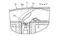
まず、本発明の第1の実施の形態について説明する。図1および図2に示した穿刺装置1は、ランセット2を装着して使用するものであり、装置本体3および搾液具4と、を備えている。  First, a first embodiment of the present invention will be described. Apuncture device 1 shown in FIGS. 1 and 2 is used with alancet 2 mounted thereon, and includes adevice body 3 and asqueezing tool 4.

装置本体3は、筐体30および穿刺機構5を備えている。  The apparatusmain body 3 includes ahousing 30 and apuncture mechanism 5.

筐体30は、後述する各種の要素を収容したものであるが、その上部に一対のガイド部31が設けられている。各ガイド部31は、矢印N′,N″方向に延びる溝として形成されている。このガイド部31は、後述する搾液具4のガイド部42を係合させるためのものであり、装置本体3に対して搾液具4を装着するときに利用されるものである。  Thehousing 30 accommodates various elements to be described later, and a pair ofguide portions 31 are provided on the upper portion thereof. Eachguide portion 31 is formed as a groove extending in the directions of arrows N ′ and N ″. Thisguide portion 31 is for engaging aguide portion 42 of thesqueezing tool 4 to be described later, and the apparatus main body. 3 is used when thesqueezing tool 4 is attached to 3.

図1および図3に示したように、穿刺機構5は、搾液具4の収容空間40aに保持された指先10を穿刺するためのものであり、ハウジング50、ランセットホルダ51および作用部52を有している。  As shown in FIGS. 1 and 3, thepuncture mechanism 5 is for puncturing thefingertip 10 held in theaccommodation space 40a of theliquid squeezing tool 4, and includes ahousing 50, alancet holder 51, and anaction portion 52. Have.

ハウジング50は、ランセット2およびランセットホルダ51を収容するためのものである。このハウジング50は、開口部53、貫通孔54、および一対の段部55を有している。  Thehousing 50 is for housing thelancet 2 and thelancet holder 51. Thehousing 50 has anopening 53, a throughhole 54, and a pair ofstepped portions 55.

開口部53は、図2および図3に良く表れているように、ランセット2を挿入する際に利用されるものであり、切欠53aを有している。切欠53aは、後述するランセット2の凸部22Cを係合させるためのものである。  As shown in FIGS. 2 and 3, theopening 53 is used when thelancet 2 is inserted, and has anotch 53 a. Thenotch 53a is for engaging aconvex portion 22C of thelancet 2 described later.

図1および図3に示したように、貫通孔54は、後述するランセットホルダ51の係合部51aの移動を許容し、その周辺部54aにおいて係合部51aを係止させるための部分である。  As shown in FIGS. 1 and 3, thethrough hole 54 is a portion for allowing movement of anengaging portion 51 a of alancet holder 51 to be described later and locking theengaging portion 51 a at theperipheral portion 54 a. .

一対の段部55は、後述するランセット2の収容部22に押圧力を作用させるためのものであり、ハウジング50の内方に向けて突出している。一対の段部55は、図3における上方側の部分がテーパ状に形成されている。  The pair ofstep portions 55 is for applying a pressing force to the accommodatingportion 22 of thelancet 2 described later, and protrudes toward the inside of thehousing 50. The pair ofstepped portions 55 are formed such that upper portions in FIG. 3 are tapered.

ランセットホルダ51は、ランセット2を保持するためのものである。ランセットホルダ51には、係合部51aおよびフランジ部51bが設けられている。係合部51aは、ハウジング50の貫通孔54の周辺部54aに係合可能なフック状に形成されている。フランジ部51bと貫通孔54の周辺部54aとの間には、コイルバネ57が配置されている。コイルバネ57は、係合部51aを貫通孔54の周辺部54aに係合させた状態では、圧縮状態となるようになっている。したがって、係合部51aが貫通孔54の周辺部54aに係合した状態を解除すれば、コイルバネ57の弾発力がフランジ部51bに作用し、ランセットホルダ51が矢印N1方向に移動させられる。フランジ部51bと段部55との間には、コイルバネ58が配置されている。コイルバネ58は、ランセットホルダ51を矢印N1方向に移動させたときに圧縮されるものであり、そのときの弾発力をフランジ部51bに作用させてランセットホルダ51を矢印N2方向に移動させるためのものである。ただし、コイルバネ58は省略してもよい。  Thelancet holder 51 is for holding thelancet 2. Thelancet holder 51 is provided with anengaging portion 51a and aflange portion 51b. Theengaging portion 51 a is formed in a hook shape that can be engaged with theperipheral portion 54 a of thethrough hole 54 of thehousing 50. Acoil spring 57 is disposed between theflange portion 51 b and theperipheral portion 54 a of the throughhole 54. Thecoil spring 57 is in a compressed state when theengaging portion 51 a is engaged with theperipheral portion 54 a of thethrough hole 54. Therefore, if the state where theengaging portion 51a is engaged with theperipheral portion 54a of thethrough hole 54 is released, the elastic force of thecoil spring 57 acts on theflange portion 51b, and thelancet holder 51 is moved in the arrow N1 direction. Acoil spring 58 is disposed between theflange portion 51 b and thestep portion 55. Thecoil spring 58 is compressed when thelancet holder 51 is moved in the direction of the arrow N1, and is used to move thelancet holder 51 in the direction of the arrow N2 by applying the elastic force at that time to theflange portion 51b. Is. However, thecoil spring 58 may be omitted.

作用部52は、ランセットホルダ51の係合部51aが貫通孔54の周辺部54aに係合した状態を解除するためのものであり、矢印N′,N″方向に移動可能とされている。すなわち、作用部52は、矢印N″方向に移動させられたときに係合部51aに干渉して係合部51aに押圧力を作用させ、係合部51aが貫通孔54の周辺部54aに係合した状態を解除することができる。この作用部52は、制御手段59により矢印N′,N″方向への移動が制御されている。もちろん、手動により作用部52を移動させるように構成することもできる。  Theaction part 52 is for releasing the state in which theengaging part 51a of thelancet holder 51 is engaged with theperipheral part 54a of the throughhole 54, and is movable in the directions of arrows N ′ and N ″. That is, when theaction portion 52 is moved in the direction of the arrow N ″, theaction portion 52 interferes with theengagement portion 51 a to exert a pressing force on theengagement portion 51 a, and theengagement portion 51 a is applied to theperipheral portion 54 a of the throughhole 54. The engaged state can be released. Theaction portion 52 is controlled to move in the directions of the arrows N ′ and N ″ by the control means 59. Of course, theaction portion 52 can be manually moved.

一方、図1および図2に示したように、搾液具4は、装置本体3に対して着脱自在とされており、本体部40、作用部41およびガイド部42を有している。  On the other hand, as shown in FIGS. 1 and 2, the liquid squeezingtool 4 is detachable from the apparatusmain body 3 and includes amain body 40, anaction part 41, and aguide part 42.

本体部40は、指先を収容するための収容空間40aと、この収容空間40aに対して指先10を出し入れするための開口部40bと、収容空間40aに挿入した指先10において、穿刺対象部位10aを露出させるための貫通孔40cを有している。  Themain body 40 includes anaccommodation space 40a for accommodating a fingertip, anopening 40b for inserting / removing thefingertip 10 into / from theaccommodation space 40a, and afingertip 10 inserted into theaccommodation space 40a. A throughhole 40c is provided for exposure.

作用部41は、図4に良く表れているように、収容空間40aから指先10を抜き出す際に、指先に対して矢印N″方向に向けた力を作用させるためのものである。この作用部41は、板バネとして構成されており、収容空間40aに指先を挿入するときに比べて、収容空間40aから指先10を抜き出すときのほうが指先10に作用する移動抵抗が大きくなるように構成されている。この作用部41は、たとえば金属板を折り曲げることにより形成することができる。また、作用部41は、たとえばインサート成形により本体部40に一体化されている。もちろん、板バネとしての作用部は、収容部に対して一体的に樹脂成形してもよい。  As shown in FIG. 4, theaction part 41 is for applying a force in the direction of the arrow N ″ to the fingertip when thefingertip 10 is extracted from the accommodation space 40a. 41 is configured as a leaf spring, and is configured such that the movement resistance acting on thefingertip 10 is greater when thefingertip 10 is extracted from theaccommodation space 40a than when the fingertip is inserted into theaccommodation space 40a. Theaction part 41 can be formed by, for example, bending a metal plate, and theaction part 41 is integrated with themain body part 40 by insert molding, for example. May be integrally molded with the housing portion.

図1および図2に示したように、ガイド部42は、矢印N′,N″方向に延びる凸部として構成されており、装置本体3のガイド部31に係合させるためのものである。  As shown in FIGS. 1 and 2, theguide portion 42 is configured as a convex portion extending in the directions of arrows N ′ and N ″, and is for engaging with theguide portion 31 of the apparatusmain body 3.

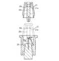
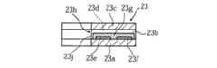
図2および図3に示したように、ランセット2は、装置本体3におけるハウジング50に挿入して使用するものである。図5〜図7に示したように、ランセット本体20、キャップ部21、収容部22、およびバイオセンサ23を備えている。  As shown in FIGS. 2 and 3, thelancet 2 is used by being inserted into thehousing 50 in the apparatusmain body 3. As shown in FIGS. 5 to 7, thelancet body 20, thecap part 21, theaccommodating part 22, and thebiosensor 23 are provided.

ランセット本体20は、穿刺針20a、穿刺針20aの針先側の端部を覆う保護部20b、および穿刺針20aにおける針先とは反対側の端部を埋設した保持部20cを有している。保護部20bと保持部20cとの間には、切り込み20dが形成されており、この切り込み20dにおいて保護部20bと保持部20cとを分離できるように構成されている。保護部20bには、凹部20eが形成されている。この凹部20eは、後述するキャップ部21の係合支持部21aを嵌合させるためのものである。  Thelancet body 20 includes apuncture needle 20a, aprotection portion 20b that covers the end of thepuncture needle 20a on the needle tip side, and a holdingportion 20c in which an end opposite to the needle tip of thepuncture needle 20a is embedded. . Anotch 20d is formed between theprotection part 20b and the holdingpart 20c, and theprotection part 20b and the holdingpart 20c can be separated at thenotch 20d. Arecess 20e is formed in theprotection part 20b. Therecess 20e is for fitting anengagement support portion 21a of thecap portion 21 described later.

図6ないし図8に示したように、キャップ部21は、収容部22に対して着脱自在に保持されているとともに、係合支持部21aを介して、ランセット本体20を保護部20cにおいて支持している。そのため、収容部22からキャップ部21を分離させるときには、ランセット本体20において保護部20cを分離させて穿刺針20aを露出させることができる。  As shown in FIGS. 6 to 8, thecap portion 21 is detachably held with respect to thehousing portion 22, and supports thelancet body 20 on theprotection portion 20c via theengagement support portion 21a. ing. Therefore, when separating thecap part 21 from theaccommodating part 22, theprotection part 20c can be separated in thelancet body 20 to expose thepuncture needle 20a.

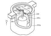
図5ないし図7に示したように、収容部22は、ランセット本体20およびバイオセンサ23を保持するためのものであり、全体として円筒状に形成されている。この収容部22は、3組の一対の凸部22Aa, 22Ab,22B,22Cを有している。  As shown in FIGS. 5 to 7, theaccommodating portion 22 is for holding thelancet body 20 and thebiosensor 23 and is formed in a cylindrical shape as a whole. Theaccommodating portion 22 has three pairs of convex portions 22Aa, 22Ab, 22B, and 22C.

図7および図9に示したように、一対の凸部22Aa,22Abは、ランセット本体20を保持部20cにおいて密着させるためのものであり、収容部22の内面22aにおいて、第1の直径軸D1に沿って設けられている。凸部22Aaからは、図7および図10に良く表れているように、バイオセンサ23を支持するための支持部22Eが延出している。この支持部22Eは、板バネとして機能するバネ部22Ea、およびバイオセンサ23が載置される載置部22Ebを有している。載置部22Ebには、切欠22Ecが設けられている。図14に仮想線で示したように、切欠22Ecの内面22Edは、載置部22Ebが自然状態よりも若干外方側に位置させた状態で、ランセット本体20の保護部20cに当接している。また、切欠22Ecの内面22Edは、ランセット本体20において保護部20cを分離させて穿刺針20aを露出させた状態では、自然状態に位置する。このとき、切欠22Ecの内面22Edと穿刺針20aとの間には、隙間が設けられる。  As shown in FIGS. 7 and 9, the pair of convex portions 22Aa and 22Ab are for bringing thelancet body 20 into close contact with the holdingportion 20c, and on theinner surface 22a of theaccommodating portion 22, the first diameter axis D1 is provided. It is provided along. As shown in FIGS. 7 and 10, asupport portion 22E for supporting thebiosensor 23 extends from the convex portion 22Aa. Thesupport portion 22E includes a spring portion 22Ea that functions as a leaf spring and a placement portion 22Eb on which thebiosensor 23 is placed. The mounting portion 22Eb is provided with a notch 22Ec. As indicated by phantom lines in FIG. 14, the inner surface 22Ed of the notch 22Ec is in contact with theprotection portion 20c of thelancet body 20 with the placement portion 22Eb positioned slightly outward from the natural state. . In addition, the inner surface 22Ed of the notch 22Ec is positioned in a natural state when thepuncture needle 20a is exposed by separating theprotective portion 20c in thelancet body 20. At this time, a gap is provided between the inner surface 22Ed of the notch 22Ec and thepuncture needle 20a.

図3および図6に示したように、一対の凸部22Bは、装置本体3におけるハウジング50の段部55に干渉させるためのものであり、収容部22の外面22bの下部位置において、図12に示したように第1直径軸D1に直交する第2直径軸D2に沿って並んで設けられている。  As shown in FIGS. 3 and 6, the pair ofconvex portions 22 </ b> B is for interfering with the steppedportion 55 of thehousing 50 in the apparatusmain body 3, and at a position below theouter surface 22 b of theaccommodating portion 22, FIG. As shown in FIG. 5, the second diameter axis D2 is provided side by side along the second diameter axis D2 orthogonal to the first diameter axis D1.

図9および図13に示したように、一対の凸部22Cは、収容部22の外面22bの上部位置において、第1の直径軸D1上に設けられている。この凸部22Cは、装置本体3のハウジング50にランセット2を挿入するときに、開口部53における切欠53aに係合させるためのものある。すなわち、凸部22Cは、ハウジング50にランセット2を挿入するときに位置決めするのに利用されるものである。  As shown in FIGS. 9 and 13, the pair ofconvex portions 22 </ b> C is provided on the first diameter axis D <b> 1 at the upper position of theouter surface 22 b of theaccommodating portion 22. Theconvex portion 22 </ b> C is for engaging with thenotch 53 a in theopening 53 when thelancet 2 is inserted into thehousing 50 of theapparatus body 3. That is, theconvex portion 22 </ b> C is used for positioning when thelancet 2 is inserted into thehousing 50.

このような収容部22は、たとえば樹脂成形により全体が弾性変形可能なように形成されている。このため、図12および図13に示したように、一対の凸部22Bに対して、第2の直径軸D2に沿って内方側に向けた力を作用させた場合には、少なくとも一対の凸部22Bが設けられた部分において収容部22が変形する。これにより、一対の凸部22Bの距離が小さくなる一方で、一対の凸部22Aの距離が大きくなり一対の凸部22Aとランセット本体20との間に隙間が形成される。その結果、ランセット本体20は、収容部22に対して、矢印N1,N2方向に相対動することができる。  Such anaccommodating part 22 is formed so that the whole can be elastically deformed by resin molding, for example. For this reason, as shown in FIG. 12 and FIG. 13, when a force directed inward along the second diameter axis D2 is applied to the pair ofconvex portions 22B, at least a pair of Theaccommodating part 22 deform | transforms in the part in which theconvex part 22B was provided. Thereby, while the distance between the pair ofconvex portions 22B is reduced, the distance between the pair ofconvex portions 22A is increased and a gap is formed between the pair ofconvex portions 22A and thelancet body 20. As a result, thelancet body 20 can move relative to theaccommodating portion 22 in the directions of arrows N1 and N2.

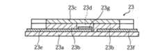
図14〜17に示したバイオセンサ23は、毛細管力により血液を移動させるとともに、血液中の特定成分、たとえばグルコースの濃度を、電極法により測定できるように構成されたものである。より具体的には、バイオセンサ23は、基板23a、一対のスペーサ23bおよびカバー23cによって構成されているとともに、これらの要素23a〜23cによって規定されるキャピラリ23dを備えている。  Thebiosensor 23 shown in FIGS. 14 to 17 is configured to move blood by capillary force and to measure the concentration of a specific component in blood, such as glucose, by an electrode method. More specifically, thebiosensor 23 includes asubstrate 23a, a pair ofspacers 23b, and acover 23c, and includes a capillary 23d defined by theseelements 23a to 23c.

基板23aの表面には、対極23e、作用極23fおよび試薬部23gが設けられている。対極23eおよび作用極23fは、図14を参酌すれば分かるように、装置本体3における分析回路(図示略)に、端子35を介して導通させるための部分である。試薬部23gは、作用極23eおよび対極23fを繋ぐように形成されており、たとえば酸化還元酵素および電子伝達物質を含んでいる。  Acounter electrode 23e, a workingelectrode 23f, and areagent part 23g are provided on the surface of thesubstrate 23a. Thecounter electrode 23e and the workingelectrode 23f are parts for conducting to an analysis circuit (not shown) in the apparatusmain body 3 via a terminal 35, as can be understood by referring to FIG. Thereagent part 23g is formed so as to connect the workingelectrode 23e and thecounter electrode 23f, and includes, for example, an oxidoreductase and an electron transfer substance.

一対のスペーサ23bは、キャピラリ23dの幅寸法および高さ寸法を規定するためのものであり、基板23aの表面において、試薬部23gを挟み込むように間隔を隔てて配置されている。これらのスペーサ23bは、たとえば両面テープにより構成される。  The pair ofspacers 23b are for defining the width dimension and the height dimension of thecapillary 23d, and are arranged on the surface of thesubstrate 23a at intervals so as to sandwich thereagent part 23g. Thesespacers 23b are made of double-sided tape, for example.

バイオセンサ23には、図10および図14に良く表れているように、半円状の切欠23hが設けられている。この切欠23hは、ランセット本体20を矢印N1方向に移動させたときに穿刺針20aの移動を許容するためのものであり、この切欠23hにおいて、キャピラリ23dに血液を導入するための開口23jが開放している。バイオセンサ23は、その切欠23hが載置部22Ebにおける切欠22Ecに対応する位置において、載置部22Ebに固定されている。したがって、載置部22Ebが自然状態にある場合には、切欠23hと穿刺針20aとの間には、隙間が設けられる。  Thebiosensor 23 is provided with asemicircular cutout 23h, as clearly shown in FIGS. Thisnotch 23h is for allowing thepuncture needle 20a to move when thelancet body 20 is moved in the direction of the arrow N1, and in thisnotch 23h, anopening 23j for introducing blood into thecapillary 23d is opened. doing. Thebiosensor 23 is fixed to the mounting portion 22Eb at a position where thenotch 23h corresponds to the notch 22Ec in the mounting portion 22Eb. Therefore, when the mounting portion 22Eb is in a natural state, a gap is provided between thenotch 23h and thepuncture needle 20a.

図2および図3に示したように、穿刺装置1を用いての穿刺作業に当たっては、まず搾液具4を取り外した状態として、ハウジング50の開口部53を介して、ハウジング50にランセット2を挿入する。図18(a)および図18(b)に示したように、ランセット2の挿入は、ハウジング50の切欠53aに対して、ランセット2の凸部22Cを位置合わせしつつ (図13参照)、ハウジング50にランセット2を押し込むことにより行うことができる。  As shown in FIGS. 2 and 3, in the puncturing operation using thepuncture device 1, the squeezingtool 4 is first removed, and thelancet 2 is attached to thehousing 50 through theopening 53 of thehousing 50. insert. As shown in FIGS. 18A and 18B, the insertion of thelancet 2 is performed while theconvex portion 22C of thelancet 2 is aligned with thenotch 53a of the housing 50 (see FIG. 13). This can be done by pushing thelancet 2 into 50.

ハウジング50にランセット2を押し込んだ場合には、ランセット本体20の保持部20cがランセットホルダ51に嵌めこまれる一方で、収容部22の凸部22Bがハウジング50の段部55に干渉する。これにより、図12および図13に示したように、収容部22が変形し、ランセット本体20が収容部22に対して相対動可能な状態とされる。このとき、ランセット本体20の保持部20cがランセットホルダ51に嵌めこまれることから、ランセット本体20は、ランセットホルダ51とともに移動することができる。また、ハウジング50にランセット2を挿入するときに、ランセットホルダ51を矢印N2方向に移動させ、ランセットホルダ51の係合部51aをハウジング50における貫通孔54の周辺部54aに係合させることができる。これにより、コイルバネ57が圧縮させられ、コイルバネ57に弾発力が蓄えられる。もちろん、ランセットホルダ51の係合部51aは、ランセット2を保持させる動作とは別に、貫通孔54の周辺部54aに係合させてもよい。つまり、ランセットホルダ51にランセット2を保持させる前に、係合部51aを貫通孔54の周辺部54aに係合させておいてもよい。  When thelancet 2 is pushed into thehousing 50, the holdingportion 20 c of thelancet body 20 is fitted into thelancet holder 51, while theconvex portion 22 </ b> B of thehousing portion 22 interferes with thestep portion 55 of thehousing 50. Thereby, as shown in FIG. 12 and FIG. 13, thehousing portion 22 is deformed, and thelancet body 20 can be moved relative to thehousing portion 22. At this time, since the holdingportion 20 c of thelancet body 20 is fitted into thelancet holder 51, thelancet body 20 can move together with thelancet holder 51. Further, when thelancet 2 is inserted into thehousing 50, thelancet holder 51 can be moved in the direction of the arrow N2, and the engagingportion 51a of thelancet holder 51 can be engaged with theperipheral portion 54a of the throughhole 54 in thehousing 50. . As a result, thecoil spring 57 is compressed, and an elastic force is stored in thecoil spring 57. Of course, the engagingportion 51 a of thelancet holder 51 may be engaged with theperipheral portion 54 a of the throughhole 54, separately from the operation of holding thelancet 2. That is, before thelancet holder 51 holds thelancet 2, the engagingportion 51 a may be engaged with theperipheral portion 54 a of the throughhole 54.

次いで、図8、図18(b)および図18(c)に示したように、ランセット2において、キャップ部21を取り外す。このとき、図8に良く表れているように、キャップ部21の係合支持部21aがランセット本体20における保護部20bの凹部20eに嵌合しているために、キャップ部21を取り外すときに、ランセット2において保護部20bが引き抜かれる。これにより、針先が露出した状態とされる。このとき、図12に示したように、バイオセンサ23は、その切欠23h、すなわち開口23jと穿刺針20aの針先との間に若干の間隔を隔てた位置に変位し、また図14を参照すれば分かるように、バイオセンサ23の作用極23eおよび対極23fは、装置本体3に設けられた端子35に接触している。この状態では、作用極23eと対極23fとの間に電圧を印加することができ、また作用極23eに供給された電子の量を電流値として測定することができる。  Next, as shown in FIGS. 8, 18 (b) and 18 (c), thecap portion 21 is removed from thelancet 2. At this time, as clearly shown in FIG. 8, since theengagement support portion 21a of thecap portion 21 is fitted in therecess 20e of theprotection portion 20b in thelancet body 20, when removing thecap portion 21, In thelancet 2, theprotection part 20b is pulled out. As a result, the needle tip is exposed. At this time, as shown in FIG. 12, thebiosensor 23 is displaced to anotch 23h, that is, a position with a slight gap between theopening 23j and the needle tip of thepuncture needle 20a, and see FIG. As can be seen, the workingelectrode 23 e and thecounter electrode 23 f of thebiosensor 23 are in contact with a terminal 35 provided in the apparatusmain body 3. In this state, a voltage can be applied between the workingelectrode 23e and thecounter electrode 23f, and the amount of electrons supplied to the workingelectrode 23e can be measured as a current value.

次いで、装置本体3に対して搾液具4を装着し、収容空間40aに指先10を挿入する(図1および図2参照)。搾液具4の装着は、搾液具4のガイド部42を装置本体3のガイド部31に係合させることにより行われる(図1および図2参照)。  Next, the squeezingtool 4 is attached to the apparatusmain body 3, and thefingertip 10 is inserted into theaccommodation space 40a (see FIGS. 1 and 2). The squeezingtool 4 is mounted by engaging theguide part 42 of the squeezingtool 4 with theguide part 31 of the apparatus main body 3 (see FIGS. 1 and 2).

次いで、図19(a)〜図19(c)に示したように、ランセット本体20を矢印N1方向に移動させて、穿刺針20aを指先10における穿刺対象部位10aに突き刺す。ランセット本体20の移動は、作用部52を図中の矢印N″方向に移動させて係合部51aに作用部52を干渉させ、ランセットホルダ51がハウジング50に係合した状態を解除することにより行われる。ランセットホルダ51の係合状態を解除した場合には、コイルバネ57の弾発力によってランセットホルダ51がランセット本体20とともに矢印N1方向に移動し、ランセット本体20の穿刺針20aは穿刺対象部位10aに突き刺さる。  Next, as shown in FIGS. 19A to 19C, thelancet body 20 is moved in the direction of the arrow N1, and thepuncture needle 20a is pierced into thepuncture target site 10a in thefingertip 10. The movement of thelancet body 20 is performed by moving theaction part 52 in the direction of the arrow N ″ in the drawing to cause theaction part 52 to interfere with theengagement part 51 a and releasing the state where thelancet holder 51 is engaged with thehousing 50. When the engaged state of thelancet holder 51 is released, thelancet holder 51 moves in the direction of the arrow N1 together with thelancet body 20 by the elastic force of thecoil spring 57, and thepuncture needle 20a of thelancet body 20 moves to the puncture target site.Pierce 10a.

図19(c)に示したように、穿刺針20aが穿刺対象部位10aに突き刺さった場合には、指先10における穿刺対象部位10aが切開され、血液が出液する。このとき、穿刺針20aとバイオセンサ23の開口23jとの間に若干の隙間が設けられているため、バイオセンサ23によって、血液の出液が阻害されることはない。図19(c)および図19(d)に示したように、穿刺針20aを穿刺対象部位10aに突き刺した後には、コイルバネ57,58の弾発力によってランセットホルダ51が後退し、穿刺針20aは指先10から即座に引き抜かれる。その後、収容空間40aから指先10を抜き出す(図1および図4参照)。このとき、図4に示したように、指先10における穿刺対象部位10aよりも根元側の部分に搾液具4の作用部41が引っ掛かり、指先10には矢印N″方向に向けた押圧力が作用する。これにより、穿刺対象部位10aから血液が搾り出され、バイオセンサ23において血液を測定するのに十分な血液を出液させることができるようになる。血液が出液する。  As shown in FIG. 19 (c), when thepuncture needle 20a pierces thepuncture target site 10a, thepuncture target site 10a in thefingertip 10 is incised, and blood is discharged. At this time, since a slight gap is provided between thepuncture needle 20a and theopening 23j of thebiosensor 23, thebiosensor 23 does not impede blood outflow. As shown in FIGS. 19 (c) and 19 (d), after thepuncture needle 20a is pierced into thepuncture target site 10a, thelancet holder 51 is retracted by the elastic force of the coil springs 57, 58, and thepuncture needle 20a. Is immediately withdrawn from thefingertip 10. Thereafter, thefingertip 10 is extracted from theaccommodation space 40a (see FIGS. 1 and 4). At this time, as shown in FIG. 4, theaction portion 41 of the squeezingtool 4 is caught on the base side of thefingertip 10 relative to thepuncture target site 10 a, and thefingertip 10 has a pressing force directed in the direction of the arrow N ″. As a result, blood is squeezed out from thepuncture target site 10a, and sufficient blood can be discharged to measure the blood in thebiosensor 23. The blood is discharged.

図20(a)に示したように、穿刺対象部位10aから出液した血液Bは、バイオセンサ23の開口23jに到達する。穿刺針20aとバイオセンサ23の開口23jとの間には、若干の隙間が設けられているため、皮膚から出液した血液は、穿刺針20aに阻害されることなく、開口23jに対して適切に導入される。バイオセンサ23では、図20(a)〜図20(c)に示したように、キャピラリ23dにおいて生じる毛細管力により、血液Bがキャピラリ23dの内部を移動する。このとき、血液Bによって試薬部23gが溶解させられ、キャピラリ23dの内部に液相反応系が構築される。液相反応系においては、血液中の特定成分、たとえばグルコースから電子が取り出され、それが作用極23eに供給される。装置本体3においては、端子35(図14参照)を介して作用極23eと対極23fとの間に電圧を印加し、作用極23eに対する電子の移動量が電流値として端子35(図14参照)によって測定される。装置本体3ではさらに、測定された電流値に基づいて、特定成分の分析、たとえばグルコース濃度の演算が行われる。  As shown in FIG. 20 (a), the blood B discharged from thepuncture target site 10a reaches theopening 23j of thebiosensor 23. Since a slight gap is provided between thepuncture needle 20a and theopening 23j of thebiosensor 23, the blood discharged from the skin is appropriately blocked with respect to theopening 23j without being blocked by thepuncture needle 20a. To be introduced. In thebiosensor 23, as shown in FIGS. 20A to 20C, the blood B moves inside thecapillary 23d by the capillary force generated in thecapillary 23d. At this time, thereagent part 23g is dissolved by the blood B, and a liquid phase reaction system is constructed inside thecapillary 23d. In the liquid phase reaction system, electrons are taken out from a specific component in blood, such as glucose, and supplied to the workingelectrode 23e. In the apparatusmain body 3, a voltage is applied between the workingelectrode 23e and thecounter electrode 23f via the terminal 35 (see FIG. 14), and the amount of movement of electrons with respect to the workingelectrode 23e is the current value as the terminal 35 (see FIG. 14). Measured by. Further, the apparatusmain body 3 analyzes a specific component based on the measured current value, for example, calculates a glucose concentration.

穿刺装置1は、搾液具4の収容空間40aから指先10を抜き出す際に、作用部41によって指先10から血液が搾り出されるように構成されている。すなわち、従来から用いられていたポンプやカフを用いることなく、作用部41を設けるといった極めて簡易な構成によって血液の出液を促進することができる。その結果、穿刺装置1は、製造コストを大きく上昇させることなく血液の出液を促進することができる。しかも、穿刺装置1では、駆動源を使用することなく、血液の出液を促進することができるために、ランニングコスト的に有利である。また、搾液具4の収容空間40aから指先10を抜き出す際に作用部41が指先に作用するため、使用者としては、血液の出液を促進するために煩わしい作業を強いられることもない。  Thepuncture device 1 is configured so that blood is squeezed out from thefingertip 10 by theaction portion 41 when thefingertip 10 is extracted from theaccommodation space 40a of the squeezingtool 4. That is, it is possible to promote blood discharge by an extremely simple configuration in which theaction portion 41 is provided without using a pump or cuff that has been conventionally used. As a result, thepuncture device 1 can promote blood outflow without significantly increasing the manufacturing cost. In addition, thepuncture apparatus 1 is advantageous in terms of running cost because it can promote blood discharge without using a drive source. Moreover, since theaction part 41 acts on a fingertip when extracting thefingertip 10 from theaccommodation space 40a of the liquid squeezingtool 4, the user is not forced to perform a troublesome work to promote blood outflow.

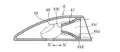
次に、本発明の第2の実施の形態について、図21および図22を参照して説明する。  Next, a second embodiment of the present invention will be described with reference to FIGS.

図21に示した搾液具4′は、本体部40′の内部に作用部41′を固定したものであるが、作用部41′の構成において、先に説明した搾液具4とは異なっている。  The squeezingtool 4 ′ shown in FIG. 21 is obtained by fixing theaction part 41 ′ inside themain body part 40 ′. However, the structure of theaction part 41 ′ is different from thesqueeze tool 4 described above. ing.

作用部41′は、図21および図22に示したように、第1開口部41a′、第2開口部41b′、収容空間41c′、およびフランジ部41d′を有しており、全体が筒状に形成されている。この作用部41′は、ゴムやエラストマーなどによって形成することによって、全体が弾性体として構成されている。  As shown in FIGS. 21 and 22, theaction portion 41 ′ has afirst opening 41 a ′, asecond opening 41 b ′, a receivingspace 41 c ′, and aflange portion 41 d ′. It is formed in a shape. Theaction portion 41 ′ is formed as an elastic body by being formed of rubber or elastomer.

第1開口部41a′は、本体部40′の内部において、抜脱方向N′側に位置させられている。この第1開口部41a′は、そのサイズが指先10の寸法よりも大きくなされている。第2開口部41b′は、本体部40′の内部において、挿入方向N″側に位置させられており、第1開口部41a′よりも小径に形成されている。この第2開口部41b′は、そのサイズが指先10の寸法よりも小さくなされており、指先10を挿通したときに、径が大きくなるように構成されている。収容空間41c′は、第1および第2開口部41a′,41b′を介して外部と連通している。フランジ部41d′は、第1開口部41a′の径を規定しているとともに、作用部41′を本体部40′に対して固定するための部分である。  Thefirst opening 41a ′ is positioned on the side of the removal direction N ′ inside themain body 40 ′. The size of thefirst opening 41 a ′ is larger than the size of thefingertip 10. Thesecond opening 41b ′ is positioned on the side in the insertion direction N ″ inside themain body 40 ′, and has a smaller diameter than thefirst opening 41a ′. Thesecond opening 41b ′. Has a size smaller than the dimension of thefingertip 10 and is configured to have a larger diameter when inserted through thefingertip 10. Theaccommodation space 41c 'has first andsecond openings 41a'. 41b ', theflange portion 41d' defines the diameter of thefirst opening portion 41a 'and is used to fix the action portion 41' to the main body portion 40 '. Part.

搾液具4′は、全体が弾性体として構成されているとともに、第1および第2開口部41a′,41b′の径が異なったものされているため、挿入方向N″に対する抵抗に比べて、抜脱方向N′に対する抵抗のほうが大きくなるように構成されている。したがって、搾液具4′では、たとえば作用部41′に挿通した格好で指先10を本体部40′の内部に収容した上で、指先10を切開した後に本体部40′から指先10を抜脱することにより、指先10から血液を搾り出すことができる。作用部41′に指先10を挿通した場合には、作用部41′の全体が弾性体として構成されているとともに、第2開口部41b′のサイズが指先10の寸法よりも小さくなされていることから、第2開口部41b′の径が大きくされる一方で、指先10における第2開口部41b′の近傍に締め付け力が作用する。これにより、指先10が鬱血させられる。一方、指先10が切開された状態で作用部41′から指先10を抜脱した場合には、指先10における第2開口部41b′の近傍に締め付け力が作用しているために、指先10からは血液が搾り出される。作用部41′においては、第2開口部41b′によって指先10が鬱血させられているために、これによって、より適切に血液を搾り出すことができる。  The squeezingtool 4 ′ is configured as an elastic body as a whole, and the first andsecond openings 41 a ′ and 41 b ′ have different diameters. In this case, in the squeezing tool 4 ', for example, thefingertip 10 is housed inside the main body 40' in a fashion that is inserted into the action part 41 '. The blood can be squeezed out of thefingertip 10 by removing thefingertip 10 from the main body 40 'after incising thefingertip 10. When thefingertip 10 is inserted into the action portion 41', the action portion Since the entire 41 'is configured as an elastic body, and the size of thesecond opening 41b' is smaller than the dimension of thefingertip 10, the diameter of thesecond opening 41b 'is increased. , Fingertip 1 A tightening force is applied in the vicinity of thesecond opening 41b 'at this point, thereby causing thefingertip 10 to become congested.On the other hand, when thefingertip 10 is removed from the action portion 41' while thefingertip 10 is incised. Since the tightening force is acting in the vicinity of thesecond opening 41b ′ in thefingertip 10, blood is squeezed out from thefingertip 10. In theaction portion 41 ′, thefingertip 10 is moved by thesecond opening 41b ′. This makes it possible to squeeze blood more appropriately because it is congested.

もちろん、指先10を切開するタイミングは、本体部40′に指先10を収容(作用部41′に指先1を挿通)した後には限定されず、本体部40′に指先10を収容(作用部41′に指先1を挿通)する前であってもよい。  Of course, the timing of incising thefingertip 10 is not limited after thefingertip 10 is accommodated in themain body portion 40 ′ (thefingertip 1 is inserted into theaction portion 41 ′), and thefingertip 10 is accommodated in themain body portion 40 ′ (the action portion 41). It may be before thefingertip 1 is inserted into '.

本発明は、上述した第1および第2の実施の形態には限定されず、種々に変更可能である。たとえば、バイオセンサ23は、搾液具4,4′に設けてもよい。  The present invention is not limited to the first and second embodiments described above, and various modifications can be made. For example, thebiosensor 23 may be provided in the squeezingtool 4, 4 ′.

本発明の第1の実施の形態に係る穿刺装置の一例を示す断面図である。It is sectional drawing which shows an example of the puncture apparatus which concerns on the 1st Embodiment of this invention.図1に示した穿刺装置の要部を一部破断して示した斜視図である。It is the perspective view which fractured | ruptured and showed the principal part of the puncture device shown in FIG.図1に示した穿刺装置における穿刺機構を説明するための要部を拡大した断面図である。It is sectional drawing to which the principal part for demonstrating the puncture mechanism in the puncture apparatus shown in FIG. 1 was expanded.図1に示した穿刺装置における搾液具を説明するための要部を拡大した断面図である。It is sectional drawing to which the principal part for demonstrating the squeezing tool in the puncture apparatus shown in FIG. 1 was expanded.図1に示した穿刺装置に装着して使用するランセットの全体斜視図である。FIG. 2 is an overall perspective view of a lancet used by being attached to the puncture device shown in FIG. 1.図5のXI−XI線に沿う断面図である。It is sectional drawing which follows the XI-XI line of FIG.図5のXII−XII線に沿う断面図である。It is sectional drawing which follows the XII-XII line | wire of FIG.図5〜図7に示したランセットにおいて、キャップ部を取り外した状態を示す断面図である。It is sectional drawing which shows the state which removed the cap part in the lancet shown in FIGS.図5のXI−XI線に沿う断面図である。It is sectional drawing which follows the XI-XI line of FIG.ランセットの内部構成を説明するための一部を切り欠いて示した要部斜視図である。It is the principal part perspective view which notched and showed a part for demonstrating the internal structure of a lancet.図10に示した状態のランセットの平面図である。It is a top view of the lancet of the state shown in FIG.ランセットの動作を説明するための断面図である。It is sectional drawing for demonstrating operation | movement of a lancet.ランセットの動作を説明するための断面図である。It is sectional drawing for demonstrating operation | movement of a lancet.ランセットに組み込まれたバイオセンサの全体斜視図である。It is a whole perspective view of the biosensor integrated in the lancet.図14に示したバイオセンサの分解斜視図である。FIG. 15 is an exploded perspective view of the biosensor shown in FIG. 14.図14のXVI−XVI線に沿う断面図である。It is sectional drawing which follows the XVI-XVI line | wire of FIG.図14のXVII−XVII線に沿う断面図である。It is sectional drawing which follows the XVII-XVII line of FIG.図1に示した穿刺装置の使用方法を説明するための要部断面図である。It is principal part sectional drawing for demonstrating the usage method of the puncture apparatus shown in FIG.穿刺機構の動作を説明するための要部断面図である。It is principal part sectional drawing for demonstrating operation | movement of a puncture mechanism.バイオセンサにおける血液の導入過程を説明するための要部断面図である。It is principal part sectional drawing for demonstrating the blood introduction process in a biosensor.本発明の第2の実施の形態に係る搾液具を示す断面図である。It is sectional drawing which shows the liquid squeezing tool which concerns on the 2nd Embodiment of this invention.図21に示した搾液具における作用部を示す斜視図である。It is a perspective view which shows the action part in the liquid squeezing tool shown in FIG.

符号の説明Explanation of symbols

1 穿刺装置
10 指先
4,4′ (穿刺装置の)搾液具
40 (搾液具の)本体部(収容部)
40a (搾液具の)収容空間
40c (搾液具の)貫通孔
41,41′ (搾液具の)作用部
41a′ (作用部の)第1開口部
41b′ (作用部の)第2開口部
DESCRIPTION OFSYMBOLS 1Puncturing device 10Fingertip 4,4 '(Puncture device) squeezing tool 40 (Liquid squeezing device) main body (accommodating portion)
40a (squeezing tool)accommodation space 40c (squeezing tool) through-hole 41, 41 '(squeezing tool) workingpart 41a' (working part)first opening 41b '(working part) second Aperture

Claims (15)

Translated fromJapanese
切開された指先から体液を絞り出すための搾液具であって、
指先を挿入するための収容空間を有する収容部と、
上記収容空間において突出し、かつ上記収容部に挿入した指先を抜脱する際に、指先に対して挿入方向に向けた力を作用させるための作用部と、
を備えたことを特徴とする、搾液具。
A squeezing tool for squeezing body fluid from an incised fingertip,
An accommodating portion having an accommodating space for inserting a fingertip;
An action part for causing a force directed in the insertion direction to act on the fingertip when the fingertip protruding in the accommodation space and inserted into the accommodation part is removed;
A squeezing tool characterized by comprising:
上記作用部は、上記収容部に指先を挿入するときの挿入抵抗に比べて、上記収容部から指先を抜脱するときの抜脱抵抗のほうが大きくなるように構成されている、請求項1に記載の搾液具。  The operation portion is configured to have a greater resistance to removal when the fingertip is removed from the housing portion than to an insertion resistance when the fingertip is inserted into the housing portion. The squeezing tool described. 上記作用部は、上記収容部に指先を挿入するときに、挿入抵抗が小さくなるように撓むことが可能なように構成されている、請求項2に記載の搾液具。  The liquid squeezing tool according to claim 2, wherein the action portion is configured to be able to bend so that an insertion resistance is reduced when a fingertip is inserted into the housing portion. 上記作用部は、板バネとして構成されている、請求項3に記載の搾液具。  The said action part is a squeeze tool of Claim 3 comprised as a leaf | plate spring. 上記収容部は、指先における出液部位に対応させた貫通孔を有している、請求項1ないし4のいずれかに記載の搾液具。  The liquid storage device according to any one of claims 1 to 4, wherein the housing portion has a through hole corresponding to a liquid discharge site on a fingertip. 皮膚に穿刺要素を突き刺して皮膚を切開させるための穿刺装置に装着して使用するものである、請求項1ないし5のいずれかに記載の搾液具。  The liquid squeezing device according to any one of claims 1 to 5, wherein the liquid squeezing device is used by being attached to a puncture device for incising the skin by inserting a puncture element into the skin. 皮膚に穿刺要素を突き刺して皮膚を切開するための装置本体と、
指先から体液を絞り出すための搾液具と、
を備えたことを特徴とする、穿刺装置。
A device body for piercing the skin with a puncture element and incising the skin;
A squeezing tool for squeezing body fluid from the fingertips;
A puncture device comprising:
上記搾液具は、指先を挿入するための収容空間を有する収容部と、上記収容空間において突出し、かつ上記本体部に挿入した指先を抜脱する際に、指先に対して挿入方向に向けた力を作用させるための作用部と、を備えている、請求項7に記載の穿刺装置。  The squeezing tool is oriented in the insertion direction with respect to the fingertip when removing the fingertip inserted into the main body portion and the accommodating portion having an accommodating space for inserting the fingertip and the accommodating space. The puncture device according to claim 7, further comprising an action portion for applying a force. 上記作用部は、上記収容部に指先を挿入するときの挿入抵抗に比べて、上記収容部から指先を抜脱するときの抜脱抵抗のほうが大きくなるように構成されている、請求項8に記載の穿刺装置。  The action portion is configured to have a greater resistance to removal when the fingertip is removed from the accommodating portion than to an insertion resistance when the fingertip is inserted into the accommodating portion. The puncture device as described. 上記作用部は、上記収容部に指先を挿入するときに、挿入抵抗が小さくなるように撓むことが可能なように構成されている、請求項9に記載の穿刺装置。  The puncture device according to claim 9, wherein the action unit is configured to be able to bend so that an insertion resistance is reduced when a fingertip is inserted into the housing unit. 上記作用部は、板バネとして構成されている、請求項10に記載の穿刺装置。  The puncture apparatus according to claim 10, wherein the action portion is configured as a leaf spring. 上記作用部は、抜脱方向側に位置する第1開口部と、挿入方向側に位置し、かつ上記第1開口部よりも径の小さい第2開口部を有している、請求項9に記載の穿刺装置。  The operation portion has a first opening located on the removal direction side and a second opening located on the insertion direction side and having a diameter smaller than that of the first opening. The puncture device as described. 上記第2開口部は、指先を挿入したときに径が大きくなるように構成されている、請求項12に記載の穿刺装置。  The puncture apparatus according to claim 12, wherein the second opening is configured to have a larger diameter when a fingertip is inserted. 上記収容部は、指先における出液部位に対応させた貫通孔を有している、請求項8ないし13のいずれかに記載の穿刺装置。  The puncture apparatus according to any one of claims 8 to 13, wherein the housing portion has a through hole corresponding to a liquid discharge site on a fingertip. 上記搾液具は、上記装置本体に対して着脱自在とされている、請求項7ないし14のいずれかに記載の穿刺装置。  The puncture device according to any one of claims 7 to 14, wherein the squeezing tool is detachable from the device main body.
JP2003368889A2003-10-292003-10-29 Squeezing tool and puncture deviceExpired - Fee RelatedJP4621850B2 (en)

Priority Applications (1)

Application NumberPriority DateFiling DateTitle
JP2003368889AJP4621850B2 (en)2003-10-292003-10-29 Squeezing tool and puncture device

Applications Claiming Priority (1)

Application NumberPriority DateFiling DateTitle
JP2003368889AJP4621850B2 (en)2003-10-292003-10-29 Squeezing tool and puncture device

Publications (3)

Publication NumberPublication Date
JP2005131009Atrue JP2005131009A (en)2005-05-26
JP2005131009A5 JP2005131009A5 (en)2006-12-14
JP4621850B2 JP4621850B2 (en)2011-01-26

Family

ID=34646418

Family Applications (1)

Application NumberTitlePriority DateFiling Date
JP2003368889AExpired - Fee RelatedJP4621850B2 (en)2003-10-292003-10-29 Squeezing tool and puncture device

Country Status (1)

CountryLink
JP (1)JP4621850B2 (en)

Cited By (4)

* Cited by examiner, † Cited by third party
Publication numberPriority datePublication dateAssigneeTitle
WO2009031314A1 (en)*2007-09-042009-03-12Panasonic CorporationBlood analysis device
JP2009542304A (en)*2006-07-062009-12-03ラピッディックス エルティーディー. Integrated blood collection and test instrument and method of use
JP2015223278A (en)*2014-05-272015-12-14株式会社テクノメデイカFingertip avascularization instrument
RU2770394C2 (en)*2016-08-242022-04-15Бектон, Дикинсон Энд КомпаниDevice for attached blood flow

Citations (2)

* Cited by examiner, † Cited by third party
Publication numberPriority datePublication dateAssigneeTitle
JP2001170031A (en)*1999-12-162001-06-26Terumo CorpHumor examination device
WO2001089383A2 (en)*2000-05-262001-11-29Roche Diagnostics GmbhSystem for removing body fluid, especially blood

Patent Citations (2)

* Cited by examiner, † Cited by third party
Publication numberPriority datePublication dateAssigneeTitle
JP2001170031A (en)*1999-12-162001-06-26Terumo CorpHumor examination device
WO2001089383A2 (en)*2000-05-262001-11-29Roche Diagnostics GmbhSystem for removing body fluid, especially blood

Cited By (8)

* Cited by examiner, † Cited by third party
Publication numberPriority datePublication dateAssigneeTitle
JP2009542304A (en)*2006-07-062009-12-03ラピッディックス エルティーディー. Integrated blood collection and test instrument and method of use
WO2009031314A1 (en)*2007-09-042009-03-12Panasonic CorporationBlood analysis device
JP5290974B2 (en)*2007-09-042013-09-18パナソニック株式会社 Blood analyzer
JP2015223278A (en)*2014-05-272015-12-14株式会社テクノメデイカFingertip avascularization instrument
RU2770394C2 (en)*2016-08-242022-04-15Бектон, Дикинсон Энд КомпаниDevice for attached blood flow
US11399755B2 (en)2016-08-242022-08-02Becton, Dickinson And CompanyDevice for obtaining a blood sample
US11771352B2 (en)2016-08-242023-10-03Becton, Dickinson And CompanyDevice for the attached flow of blood
US12082932B2 (en)2016-08-242024-09-10Becton, Dickinson And CompanyDevice for obtaining a blood sample

Also Published As

Publication numberPublication date
JP4621850B2 (en)2011-01-26

Similar Documents

PublicationPublication DateTitle
JP4489704B2 (en) Lancet and lancing device
EP1671584B1 (en)Lancing unit and lancing apparatus
JP4647898B2 (en) Body fluid sample capture test apparatus and cartridge
CN103079464B (en)Measurement data is allowed to be made up of blood sample
US20110130781A1 (en)Method of setting lancing member to lancing device, lancing device, and cam mechanism
CN103140163B (en) Allows for blood sample measurements
CN103079465B (en) blood sample
CN103096795B (en)Blood sample collection
JP4621850B2 (en) Squeezing tool and puncture device
JP4484669B2 (en) Puncture device
JP4762341B2 (en) Puncture device
TW201343139A (en)An apparatus for eliciting a blood sample
CN104080403A (en)Apparatus for eliciting blood sample
TW201343138A (en)Apparatus comprising a lancet
JP4958275B2 (en) Needle integrated sensor
CN104159514B (en) Devices for drawing blood samples
JP4621872B2 (en) Cam mechanism
JP2015506218A (en) Device for drawing blood samples
JP2015506216A (en) cartridge
TW201340946A (en)An apparatus for eliciting a blood sample
JP2015503969A (en) Cartridge for insertion into an instrument, instrument for receiving the cartridge, and system comprising an instrument and a cartridge
TW201340947A (en)An apparatus for eliciting a blood sample
JP2008302256A (en)Puncture device
TW201340944A (en)Capacitive sensor
JP2008206616A (en) Needle integrated sensor

Legal Events

DateCodeTitleDescription
A521Request for written amendment filed

Free format text:JAPANESE INTERMEDIATE CODE: A523

Effective date:20061025

A621Written request for application examination

Free format text:JAPANESE INTERMEDIATE CODE: A621

Effective date:20061025

A977Report on retrieval

Free format text:JAPANESE INTERMEDIATE CODE: A971007

Effective date:20091006

A131Notification of reasons for refusal

Free format text:JAPANESE INTERMEDIATE CODE: A131

Effective date:20091208

A521Request for written amendment filed

Free format text:JAPANESE INTERMEDIATE CODE: A523

Effective date:20100208

A02Decision of refusal

Free format text:JAPANESE INTERMEDIATE CODE: A02

Effective date:20100406

A521Request for written amendment filed

Free format text:JAPANESE INTERMEDIATE CODE: A523

Effective date:20100705

A911Transfer to examiner for re-examination before appeal (zenchi)

Free format text:JAPANESE INTERMEDIATE CODE: A911

Effective date:20100708

TRDDDecision of grant or rejection written
A01Written decision to grant a patent or to grant a registration (utility model)

Free format text:JAPANESE INTERMEDIATE CODE: A01

Effective date:20100831

A01Written decision to grant a patent or to grant a registration (utility model)

Free format text:JAPANESE INTERMEDIATE CODE: A01

A61First payment of annual fees (during grant procedure)

Free format text:JAPANESE INTERMEDIATE CODE: A61

Effective date:20100928

R150Certificate of patent or registration of utility model

Free format text:JAPANESE INTERMEDIATE CODE: R150

FPAYRenewal fee payment (event date is renewal date of database)

Free format text:PAYMENT UNTIL: 20131112

Year of fee payment:3

LAPSCancellation because of no payment of annual fees

[8]ページ先頭

©2009-2025 Movatter.jp