JP2005128410A - Electro-optical device and electronic apparatus - Google Patents
Electro-optical device and electronic apparatusDownload PDFInfo
- Publication number
- JP2005128410A JP2005128410AJP2003366016AJP2003366016AJP2005128410AJP 2005128410 AJP2005128410 AJP 2005128410AJP 2003366016 AJP2003366016 AJP 2003366016AJP 2003366016 AJP2003366016 AJP 2003366016AJP 2005128410 AJP2005128410 AJP 2005128410A
- Authority
- JP
- Japan
- Prior art keywords
- electro
- tft
- optical device
- channel width
- thin film
- Prior art date
- Legal status (The legal status is an assumption and is not a legal conclusion. Google has not performed a legal analysis and makes no representation as to the accuracy of the status listed.)
- Granted
Links
- 239000003990capacitorSubstances0.000claimsabstractdescription42
- 239000011159matrix materialSubstances0.000claimsabstractdescription12
- 239000010408filmSubstances0.000claimsdescription16
- 239000010409thin filmSubstances0.000claimsdescription16
- 229910021420polycrystalline siliconInorganic materials0.000claimsdescription9
- 238000005401electroluminescenceMethods0.000claimsdescription7
- 229920005591polysiliconPolymers0.000claimsdescription6
- 239000004065semiconductorSubstances0.000claimsdescription2
- 238000010586diagramMethods0.000description9
- 239000010410layerSubstances0.000description8
- 230000002093peripheral effectEffects0.000description6
- 239000000758substrateSubstances0.000description4
- XUIMIQQOPSSXEZ-UHFFFAOYSA-NSiliconChemical compound[Si]XUIMIQQOPSSXEZ-UHFFFAOYSA-N0.000description2
- 239000003086colorantSubstances0.000description2
- 230000007547defectEffects0.000description2
- 239000002346layers by functionSubstances0.000description2
- 239000002184metalSubstances0.000description2
- 229910052710siliconInorganic materials0.000description2
- 239000010703siliconSubstances0.000description2
- -1and the likeSubstances0.000description1
- 239000011521glassSubstances0.000description1
- 230000005525hole transportEffects0.000description1
- 239000012535impuritySubstances0.000description1
- 229910010272inorganic materialInorganic materials0.000description1
- 239000011147inorganic materialSubstances0.000description1
- 238000004519manufacturing processMethods0.000description1
- 229910021421monocrystalline siliconInorganic materials0.000description1
- 230000003287optical effectEffects0.000description1
- 239000011368organic materialSubstances0.000description1
- 230000005641tunnelingEffects0.000description1
Images


Landscapes
- Electroluminescent Light Sources (AREA)
- Devices For Indicating Variable Information By Combining Individual Elements (AREA)
Abstract
Translated fromJapaneseDescription
Translated fromJapanese本発明は、多数の画素がマトリクス状に配置された電気光学装置、およびそれを備えた電子機器に関するものである。 The present invention relates to an electro-optical device in which a large number of pixels are arranged in a matrix, and an electronic apparatus including the electro-optical device.
各種の電気光学装置のうち、エレクトロルミネッセンス(以下、ELという)表示装置は、マトリクス状に配置された多数の画素の各々にEL素子を備えるとともに、各画素には、EL素子に印加する電流を供給する駆動用トランジスタ、この駆動用トランジスタのゲートに接続された蓄積容量に直列に接続されて蓄積容量にデータ信号を書き込むタイミングを制御する薄膜トランジスタ(以下、TFTという)などの複数のスイッチング素子を備えている。そして、TFTをオン・オフさせて所定の電圧を蓄積容量に記憶させることにより、電源線の電圧を駆動用トランジスタのゲート電圧を制御し、EL素子に流れる電流を制御している(例えば、特許文献1、2参照)。 Among various electro-optical devices, an electroluminescence (hereinafter referred to as EL) display device includes an EL element in each of a large number of pixels arranged in a matrix, and each pixel receives a current applied to the EL element. Provided with a plurality of switching elements such as a driving transistor to be supplied and a thin film transistor (hereinafter referred to as TFT) that is connected in series to a storage capacitor connected to the gate of the driving transistor and controls the timing of writing a data signal to the storage capacitor ing. Then, by turning on / off the TFT and storing a predetermined voltage in the storage capacitor, the voltage of the power supply line is controlled by the gate voltage of the driving transistor, and the current flowing through the EL element is controlled (for example, patents)
なお、EL素子は従来は無機の材料が検討されていたが、最近ではより低電圧で発光効率の高い有機材料の有機EL素子を使った表示装置が実用化され始めている。
上記EL表示装置において、駆動用トランジスタについては飽和領域で動作させるため、ゲート電圧の変化に対する電流変化が急峻である。従って、ゲートバイアスを正確に印加させる必要があり、そのためには、蓄積容量に電荷を正確に保持させる必要がある。 In the EL display device, since the driving transistor is operated in the saturation region, the current change with respect to the change in the gate voltage is steep. Accordingly, it is necessary to accurately apply the gate bias, and for that purpose, it is necessary to accurately hold the charge in the storage capacitor.
しかしながら、従来は、蓄積容量に直列に接続されたスイッチング素子において、オフ時に流れる電流(オフリーク電流)を小さく抑えるための対策が採られていないので、蓄積容量に電荷を正確に保持させることができない。その結果、駆動用トランジスタのゲートバイアスが変化して、EL素子に流れる電流も変化する。そのゲートバイアスの変化は素子の製造ばらつきをよく反映するために均一で品位の高い階調表示を行えないという問題点がある。 However, conventionally, in a switching element connected in series with a storage capacitor, no measures have been taken to suppress the current that flows when it is turned off (off-leakage current), and therefore it is not possible to accurately hold the charge in the storage capacitor. . As a result, the gate bias of the driving transistor changes, and the current flowing through the EL element also changes. The change in the gate bias reflects the manufacturing variation of the element well, and there is a problem that uniform and high-quality gradation display cannot be performed.
とりわけ、EL表示装置では、EL素子に比較的大きな電流を流す必要があることから、TFTについては低温ポリシリコン膜で能動層を形成している。低温ポリシリコン膜を用いたTFTでは、その多結晶の粒界に多くの欠陥が存在する。このため、このような欠陥により形成されたエネルギー準位を介したトンネリングに起因したオフリーク電流がかなり大きく、かつ、かかるオフリーク電流を単結晶シリコン膜を用いたトランジスタ並みに小さくすることは困難である。 In particular, in an EL display device, since a relatively large current needs to flow through the EL element, an active layer is formed of a low-temperature polysilicon film for the TFT. A TFT using a low-temperature polysilicon film has many defects at the polycrystalline grain boundaries. For this reason, the off-leakage current due to tunneling through the energy level formed by such a defect is quite large, and it is difficult to make the off-leakage current as small as a transistor using a single crystal silicon film. .
以上の問題点に鑑みて、本発明では、多数の画素がマトリクス状に配置された電気光学装置、およびそれを備えた電子機器において、各画素にオフリーク電流を低減したTFTを適材適所に用いることにより、表示品位の向上を図ることのできる構成を提供することにある。 In view of the above problems, in the present invention, in an electro-optical device in which a large number of pixels are arranged in a matrix and an electronic apparatus including the same, a TFT with reduced off-leakage current is used for each pixel in an appropriate place. Accordingly, it is an object of the present invention to provide a configuration capable of improving display quality.
上記課題を解決するために、本発明では、マトリクス状に配置された多数の画素の各々に、少なくとも、電気光学素子、および該電気光学素子を駆動するための1ないし複数のトランジスタを備えた電気光学装置において、前記多数の画素には、前記トランジスタのうちの少なくとも1つに、ソース領域側のチャネル幅寸法とドレイン領域側のチャネル幅寸法が相違する非対称構造のTFTが用いられた複数の画素が含まれていることを特徴とする。 In order to solve the above-described problems, in the present invention, each of a large number of pixels arranged in a matrix has at least an electro-optic element and an electric device including one or more transistors for driving the electro-optic element. In the optical device, the plurality of pixels include a plurality of pixels in which at least one of the transistors includes a TFT having an asymmetric structure in which a channel width dimension on the source region side and a channel width dimension on the drain region side are different. Is included.
本願明細書におけるチャネル幅寸法とは、チャネルを平面的にみたときに、チャネル長方向と直交する方向の寸法を意味する。また、チャネル領域とソース・ドレイン領域との境界部分が円弧状の場合には、その周方向における寸法を意味する。 The channel width dimension in the present specification means a dimension in a direction orthogonal to the channel length direction when the channel is viewed in a plane. Further, when the boundary portion between the channel region and the source / drain region is arcuate, it means the dimension in the circumferential direction.
本発明において、前記非対称構造のTFTがnチャネル型の場合には、ソース・ドレイン領域のうち、オフ時に高電位側となる方にチャネル幅寸法の小さい方を配置する。また、前記非対称構造のTFTがpチャネル型である場合には、ソース・ドレイン領域のうち、オフ時に低電位側となる方にチャネル幅寸法の小さい方を配置する。 In the present invention, when the TFT having the asymmetric structure is an n-channel type, the smaller channel width dimension is arranged on the higher potential side when the transistor is turned off in the source / drain region. In the case where the TFT having the asymmetric structure is a p-channel type, the smaller channel width dimension is arranged on the lower side of the source / drain region when it is off.
本発明において、前記電気光学素子がEL素子であり、前記多数の画素の各々には、前記トランジスタとして、少なくとも、前記EL素子に印加する電流を供給する駆動用トランジスタと、前記駆動用トランジスタのゲートに接続された蓄積容量と、前記蓄積容量に直列に接続されて、当該蓄積容量にデータ信号を書き込むタイミングを制御する第1のスイッチング素子とが設けられている場合には、前記多数の画素には、前記第1のスイッチング素子として前記非対称構造のTFTが用いられている複数の画素が含まれている。 In the present invention, the electro-optic element is an EL element, and each of the plurality of pixels includes, as the transistor, a driving transistor that supplies at least a current to be applied to the EL element, and a gate of the driving transistor. And a first switching element that is connected in series to the storage capacitor and that controls the timing of writing a data signal to the storage capacitor. Includes a plurality of pixels in which the TFT having the asymmetric structure is used as the first switching element.
本発明において、前記非対称構造のTFTを備えた複数の画素のいずれにおいても、ソース・ドレイン領域のうち、チャネル幅寸法の小さい方が前記蓄積容量の側に接続されているか、チャネル幅寸法の大きい方が前記蓄積容量の側に接続されているかが同一である場合、前記非対称構造のTFTを備えた複数の画素には、ソース・ドレイン領域のうち、チャネル幅寸法の小さい方を前記蓄積容量の側に接続された画素と、チャネル幅寸法の大きな方を前記蓄積容量の側に接続された画素とが含まれている場合がある。 In the present invention, in any of the plurality of pixels including the TFT having the asymmetric structure, a smaller channel width dimension of the source / drain regions is connected to the storage capacitor side or the channel width dimension is larger. If the same is connected to the storage capacitor side, the plurality of pixels having the asymmetrical TFTs have a smaller channel width dimension of the source / drain regions. In some cases, a pixel connected to the storage capacitor and a pixel having a larger channel width dimension connected to the storage capacitor may be included.
本発明において、前記電気光学素子は、EL素子などといった電流駆動型発光素子である。 In the present invention, the electro-optical element is a current-driven light emitting element such as an EL element.
また、前記電流駆動型発光素子が、例えば、EL素子である場合には、前記多数の画素は各々、前記トランジスタとして、少なくとも、前記EL素子に印加する電流を制御する駆動用トランジスタと、前記駆動用トランジスタのゲートに接続された蓄積容量と、前記蓄積容量に直列に接続されて、当該蓄積容量にデータ信号を書き込むタイミングを制御する第1のスイッチング素子とを備えており、前記多数の画素には、前記第1のスイッチング素子として前記非対称構造のTFTが用いられている複数の画素が含まれている。 In the case where the current-driven light-emitting element is, for example, an EL element, each of the plurality of pixels includes, as the transistor, at least a driving transistor that controls a current applied to the EL element, and the driving A storage capacitor connected to the gate of the transistor, and a first switching element connected in series to the storage capacitor to control the timing of writing a data signal to the storage capacitor. Includes a plurality of pixels in which the TFT having the asymmetric structure is used as the first switching element.
ここで、前記多数の画素の各々には、前記トランジスタとして、前記駆動用トランジスタ、および前記第1のスイッチング素子に加えて、前記駆動用トランジスタに直列に接続されて前記EL素子に流す電流をオンオフする第2のスイッチング素子と、前記第1のスイッチング素子に対して前記蓄積容量とは反対側に直列接続された第3のスイッチング素子とを備える場合があり、このような場合、前記第1のスイッチング素子と前記第3のスイッチング素子との電気的な接続点と、前記駆動用トランジスタと前記第2のスイッチング素子との電気的な接続点とが短絡されている。 Here, in each of the large number of pixels, in addition to the driving transistor and the first switching element, a current that is connected in series to the driving transistor and flows through the EL element is turned on and off as the transistor. And a third switching element connected in series on the opposite side of the storage capacitor with respect to the first switching element. In such a case, the first switching element may include the first switching element. An electrical connection point between the switching element and the third switching element and an electrical connection point between the driving transistor and the second switching element are short-circuited.
本発明において、前記EL素子として、各色に対応する複数種類のEL素子が形成されている場合があり、この場合、いずれの色に対応する画素においても、ソース・ドレイン領域のうち、チャネル幅寸法の小さい方が前記蓄積容量の側に接続されているか、チャネル幅寸法の大きい方が前記蓄積容量の側に接続されているかが同一である構成を採用することがある。 In the present invention, there are cases where a plurality of types of EL elements corresponding to the respective colors are formed as the EL elements. In this case, in the pixels corresponding to any color, the channel width dimension in the source / drain regions. A configuration may be adopted in which the smaller one is connected to the storage capacitor side or the larger channel width dimension is connected to the storage capacitor side.
また、前記EL素子として、各色に対応する複数種類のEL素子が形成されている場合があり、この場合、ソース・ドレイン領域のうち、チャネル幅寸法の小さい方が前記蓄積容量の側に接続されているか、チャネル幅寸法の大きい方が前記蓄積容量の側に接続されているかが、画素が対応する色によって相違している構成を採用することもある。EL素子の場合、色によってダイオード特性が相違する場合があり、この場合、前記非対称構造のTFTのオフ時、このTFTに加わる電圧の向きが変わることがある。従って、EL素子の特性に非対称構造のTFTの向きを合わせることが好ましい。 In addition, a plurality of types of EL elements corresponding to the respective colors may be formed as the EL elements. In this case, the smaller channel width dimension of the source / drain regions is connected to the storage capacitor side. In other cases, the pixel may be different depending on the corresponding color depending on whether the larger channel width dimension is connected to the storage capacitor. In the case of an EL element, the diode characteristics may differ depending on the color. In this case, when the TFT having the asymmetric structure is turned off, the direction of the voltage applied to the TFT may change. Therefore, it is preferable to match the orientation of the asymmetrical TFT with the characteristics of the EL element.
本発明は、前記非対称構造のTFTの能動層が低温ポリシリコン膜から構成されている場合に適用すると、オフリーク電流を低減するのに効果的である。低温ポリシリコン膜で能動層を形成した場合、基板としてガラス基板を使えるという利点があるが、オフリーク電流が大きいという欠点がある。従って、この欠点を非対象構造で解消すれば、低温ポリシリコン膜を用いたTFTの利点を最大限、活かすことができる。 The present invention is effective in reducing off-leakage current when applied to the case where the active layer of the TFT having the asymmetric structure is composed of a low-temperature polysilicon film. When the active layer is formed of a low-temperature polysilicon film, there is an advantage that a glass substrate can be used as a substrate, but there is a disadvantage that off-leakage current is large. Therefore, if this disadvantage is eliminated by the non-target structure, the advantages of the TFT using the low-temperature polysilicon film can be utilized to the maximum extent.
本発明において、前記非対称構造のTFTでは、ソース領域、チャネル領域、およびドレイン領域がこの順に同心円状に配置されている構成、ソース領域、チャネル領域、およびドレイン領域がこの順に円弧状に配置されている構成、および半導体膜が三角あるいは台形の平面形状をもって形成され、その高さ方向において、ソース領域、チャネル領域、およびドレイン領域がこの順に配置されている構成などを採用することができ、このような構造を採用すれば、ソース領域側のチャネル幅寸法とドレイン領域側のチャネル幅寸法とを相違させることができる。 In the present invention, in the TFT having the asymmetric structure, the source region, the channel region, and the drain region are arranged concentrically in this order, and the source region, the channel region, and the drain region are arranged in an arc shape in this order. And a structure in which the semiconductor film is formed with a triangular or trapezoidal planar shape, and in the height direction, the source region, the channel region, and the drain region are arranged in this order. If such a structure is employed, the channel width dimension on the source region side and the channel width dimension on the drain region side can be made different.
本発明においては、前記非対称構造のTFTがダブルゲート構造を備えている構成であってもよい。 In the present invention, the asymmetric TFT may have a double gate structure.
本発明においては、前記非対称構造のTFTがLDD構造あるいはオフセットゲート構造を備えていることが好ましい。このように構成すると、オフリーク電流をさらに低減できるという利点がある。 In the present invention, the asymmetric TFT preferably has an LDD structure or an offset gate structure. This configuration has an advantage that the off-leakage current can be further reduced.
本発明を適用した電気光学装置は、例えば、モバイルコンピュータや携帯電話機などといった電子機器の表示部として用いられる。 The electro-optical device to which the present invention is applied is used as a display unit of an electronic apparatus such as a mobile computer or a mobile phone.
本発明では、マトリクス状に配置された多数の画素では、ソース領域側のチャネル幅寸法とドレイン領域側のチャネル幅寸法が相違する非対称構造のTFTが用いられており、非対称構造のTFTがnチャネル型の場合には、ソース・ドレイン領域のうち、オフ時に高電位側となる方にチャネル幅寸法の小さい方が配置され、非対称構造のTFTがpチャネル型である場合には、ソース・ドレイン領域のうち、オフ時に低電位側となる方にチャネル幅寸法の小さい方が配置されている。このような非対称構造のTFTではオフリーク電流が極めて小さいため、電気光学素子を安定した条件下で駆動することができる。それ故、階調表示を良好に行えるなど、表示の品位を向上することができる。 In the present invention, a large number of pixels arranged in a matrix use an asymmetric TFT in which the channel width dimension on the source region side and the channel width dimension on the drain region side are different. In the case of the type, of the source / drain regions, the one with the smaller channel width dimension is arranged on the higher potential side when off, and when the TFT having an asymmetric structure is a p-channel type, the source / drain regions Of these, the one with the smaller channel width dimension is disposed on the low potential side when turned off. In such an asymmetric TFT, the off-leakage current is extremely small, so that the electro-optic element can be driven under stable conditions. Therefore, display quality can be improved, such as good gradation display.
以下、図面を参照して本発明の実施の形態を説明する。 Embodiments of the present invention will be described below with reference to the drawings.
図1および図2は、本発明を適用したアクティブマトリクス型のEL表示装置のブロック図、およびその画素の構成を示す説明図である。図3は、本発明を適用したEL表示装置の電流プログラムの様子を示す説明図である。 FIG. 1 and FIG. 2 are a block diagram of an active matrix EL display device to which the present invention is applied, and an explanatory diagram showing a configuration of the pixel. FIG. 3 is an explanatory diagram showing a state of current programming of the EL display device to which the present invention is applied.
図1および図2に示すように、EL表示装置1では、基板10上の画像表示領域13に多数の画素11がマトリクス状に配置されており、その周辺領域には、データ線駆動回路12と走査線駆動回路14とが構成されている。EL表示装置1において、多数の画素11の各々には、電流駆動型発光素子(電気光学素子)としてのEL素子20と、EL素子20に印加する電流を制御するpチャネル型のTFTからなる駆動用トランジスタ30と、駆動用トランジスタ30のゲートに接続された蓄積容量40と、蓄積容量40に直列に接続されて、蓄積容量40にデータ信号を書き込むタイミングを制御するnチャネル型の第1のTFT50(第1のスイッチング素子)とが構成されている。また、多数の画素11の各々には、駆動用トランジスタ30、および第1のTFT50に加えて、駆動用トランジスタ50に直列に接続されてEL素子20に流す電流をオンオフするためのnチャネル型の第2のTFT60(第2のスイッチング素子)と、第1のTFT50に対して蓄積容量40と反対側に直列に接続されたnチャネル型の第3のTFT70(第3のスイッチング素子)とが構成されており、第1のTFT50と第3のTFT70との電気的な接続点55と、駆動用トランジスタ30と第2のTFT60との電気的な接続点35とは短絡されている。 As shown in FIGS. 1 and 2, in the
EL素子20は、図示を省略するが、画素電極上に電子輸送層、発光層、正孔輸送層などからなる少なくとも1層の有機機能層(EL層)、および金属電極(反射膜)が積層されたものであり、画素電極と金属電極との間に電圧を加えることにより、有機機能層(EL層)が発光する。 Although not shown, the
データ線駆動回路12は、水平同期信号に合わせて階調データに変換された1ライン分の映像信号をデータ線16に供給する一方、走査線駆動回路14は、第1のTFT50と第3のTFT70のオン・オフ動作を制御する信号を第1の走査線17を供給するとともに、第2のTFT60のオン・オフ動作を制御するための信号を第2の走査線18に供給する。 The data line driving
このようなEL表示装置1においては、選択行では第1の走査線17を介して第1のTFT50、および第3のTFT70をオン状態とするための信号が供給され、第2の走査線18には第2のTFT60をオフ状態とするための信号を供給される。これに対して、非選択行では第1の走査線17を介して第1のTFT50、および第3のTFT70をオフ状態とするための信号が供給され、第2の走査線18には第2のTFT60をオン状態とするための信号を供給される。 In such an
従って、選択行においては、第1のTFT50および第3のTFT70がオン状態になることにより、データ線16より所定の電流が流れる。これにより、駆動用トランジスタ30は、ゲートとドレインが短絡されて概ね同電位の状態となり、駆動用トランジスタ30と第3のTFT70を通じて所定の電流(EL素子20に流すべき電流値)が流れる。このとき、駆動用トランジスタ70のゲート−ドレインの電圧は、駆動用トランジスタ70に所定の電流が流れるような電圧値となり、蓄積容量40にはその時のゲート電圧分の電荷が蓄積される。すなわち、第1の走査線17にオン電圧を印加することにより、第3のTFT70を介して、駆動用トランジスタ30にEL素子20に流すべき所定の電流を流し、蓄積容量40は、この電流を流すのに見合った駆動用トランジスタ30のゲート電圧値を記憶することになる(電流プログラム)。 Accordingly, in the selected row, a predetermined current flows from the
このような電流プログラムを行う際、駆動用トランジスタ30はゲートとドレインが短絡されて概ね同電位の状態となるから、駆動用トランジスタ30は常に飽和領域で動作する。つまり、図3のpチャネル型トランジスタの特性曲線(ドレイン−ソース電圧Vds対ドレイン−ソース電流I)において、実線L10で示すVds=Vgsを満たすバイアス曲線上に限り駆動用トランジスタ30の動作が許容される。 When performing such a current program, the driving transistor 30 is always in the saturation region because the gate and the drain are short-circuited and become substantially at the same potential. That is, the operation of the driving transistor 30 is allowed only on the bias curve satisfying Vds = Vgs shown by the solid line L10 in the characteristic curve (drain-source voltage Vds vs. drain-source current I) of the p-channel transistor of FIG. The
一方、非選択期間になると、第2のTFT60がオン状態となり、第1のTFT50および第3のTFT70はオフ状態になる。そして、選択期間で蓄積容量40に保持されたゲート電圧Vgsで、電源線19から駆動用トランジスタ30に流れる電流が規定される。この電流値は上述の電流プログラムされた所定の電流値に一致するはずである。その結果、本来、EL素子20にはその所定の電流が流れ、EL素子20が所望の輝度で発光するはずである。 On the other hand, in the non-selection period, the
しかしながら、第2のTFT60がオン状態になって、EL素子16に電流が流れる動作に移行するときにバイアスの変動が発生する。駆動用トランジスタのゲート電圧Vgsは一定のまま保持されているから、駆動用トランジスタはゲート電圧Vgsを一定とした場合の電流曲線である実線L1上に限り変化が可能である。他方、EL素子16はダイオード型の特性を有しているので実線L21の電流曲線に従って動作する。動作のバイアス点は駆動用トランジスタの動作曲線である実線L1とEL素子の電流曲線である実線L21との交点で決定される。 However, the bias variation occurs when the
つまり電流プログラム時からEL発光動作へ移行するときに、いわば駆動用トランジスタ20のドレイン−ソース電圧VdsがポイントP11からポイントP12に示す位置にシフトする。オフ状態にある第1のTFT50では、電流プログラム時にはほぼ等しかったソース電位とドレイン電位は、この電圧変化を受けてソース電位がドレイン電位よりも高くなる。そのために、第1のTFT50のオフリーク電流が大きいと蓄積容量40に保持されていた電荷が変化するために、駆動用トランジスタTFT30に対するゲートバイアスが上昇することになる。それは結果的には発光素子の輝度を変化させることになる。 That is, when shifting from the current programming to the EL light emission operation, the drain-source voltage Vds of the driving
そこで、本形態では、第1のTFT50として、以下の非対称構造のTFTを用いる。 Therefore, in this embodiment, the following asymmetric structure TFT is used as the
[非対称構造のTFTの構成]
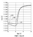
図4(A)、(B)は、本発明に係る非対称構造のTFTの平面図、および断面図である。図5は、非対称構造のTFT、従来のセルフアライン構造のTFT、および従来のLDD構造のTFTのゲート−ソース電圧と、ドレイン−ソース電流の関係を示すグラフである。[Configuration of TFT with asymmetric structure]
4A and 4B are a plan view and a cross-sectional view of a TFT having an asymmetric structure according to the present invention. FIG. 5 is a graph showing the relationship between the gate-source voltage and the drain-source current of an asymmetric TFT, a conventional self-aligned TFT, and a conventional LDD TFT.
本形態において、第1のTFT50として用いた非対称構造のTFTは、図4に示すように、円形の低温多結晶シリコン膜100に対して、その中心側から外周側に向けて、高濃度ソース領域121および低濃度ソース領域122を備えたソース領域120と、チャネル領域110と、低濃度ドレイン領域132および高濃度ドレイン領域131を備えたドレイン領域130とがこの順に同心円状に形成されている。高濃度ソース領域121および高濃度ドレイン領域131には、ソース電極125、およびドレイン電極135が各々、電気的に接続し、チャネル領域110に対しては、ゲート絶縁膜140を介してゲート電極115が対峙している。 In this embodiment, as shown in FIG. 4, the asymmetric TFT used as the
ここで、ソース領域120は中心側にある一方、ドレイン領域130は外周側にあるため、低濃度ソース領域122とチャネル領域110との界面の周方向における長さ寸法(チャネル幅寸法)は、低濃度ドレイン領域122とチャネル領域110との界面の周方向における長さ寸法(チャネル幅寸法)より短い。従って、図4に示すTFTは、ソース領域120側のチャネル幅寸法とドレイン領域130側のチャネル幅寸法が相違する非対称構造のTFTである。しかも、ここに示すTFTは、低濃度ソース領域122および低濃度ドレイン領域132を備えたLDD構造を有している。なお、低濃度ソース領域122および低濃度ドレイン領域132に相当する領域に不純物を導入せず、チャネル領域110と同様なシリコン膜にしておけば、オフセットゲート構造をもつ非対称構造のTFTを構成することができる。 Here, since the
このように構成した非非対称構造のTFTのゲート−ソース電圧とドレイン−ソース電流の関係は、図5に実線L31で示すように、実線L32で示す従来のセルフアライン構造のTFTと比較してオフリーク電流がかなり小さく、実線L33で示す従来の一般的な平行電極型のLDD構造のTFTと比較してもオフリーク電流が小さい。 The relationship between the gate-source voltage and the drain-source current of the non-asymmetric TFT configured as described above is off-leakage as compared with the conventional self-aligned TFT shown by the solid line L32 as shown by the solid line L31 in FIG. The current is considerably small, and the off-leakage current is small even when compared with a conventional general parallel electrode type LDD structure TFT indicated by a solid line L33.
それ故、図5に示す非対称のTFTを第1のTFT50として用いた際、第1のTFT50がオフ状態にあるとき、チャネル幅寸法の小さいソース領域120側が高電位側であり、チャネル幅寸法の大きなドレイン領域130側が低電位側になるので、第1のTFT50では、オフリーク電流が小さい。それ故、蓄積容量40の電荷を正確が保持されるので、駆動用トランジスタ30のゲートバイアスが変動しない。よって、EL素子20には、所定の電流が流れ続けるので、品位の高い階調表示を行うことができる。 Therefore, when the asymmetric TFT shown in FIG. 5 is used as the
[非対称構造のTFTのその他の構成]
図6(A)、(B)、(C)、(D)は、本発明に係る別の非対称構造のTFTの平面図である。なお、図6(A)、(B)、(C)、(D)に示すTFTは、基本的な構成が図4(A)、(B)に示すTFTと共通しているので、共通する部分には同一の符号を付して、それらの説明を省略する。[Other configuration of asymmetric TFT]
6A, 6B, 6C, and 6D are plan views of another asymmetric TFT according to the present invention. Note that the TFTs shown in FIGS. 6A, 6B, 6C, and 6D have the same basic configuration as the TFTs shown in FIGS. 4A and 4B, and are therefore common. Parts are denoted by the same reference numerals, and description thereof is omitted.
本発明において、第1のTFT50として使用可能な非対称構造のTFTとしては、図6(A)に示すように、半円形の低温多結晶シリコン膜100に対して、その内周側から外周側に向けて、高濃度ソース領域121および低濃度ソース領域122を備えたソース領域120と、チャネル領域110と、低濃度ドレイン領域132および高濃度ドレイン領域131を備えたドレイン領域130がこの順に円弧状に配列されたものであってもよい。 In the present invention, as an asymmetrical TFT that can be used as the
また、図6(B)に示すように、図6(A)に示すTFTを2つ、同一方向に並べ、一方のTFTの高濃度ソース領域と、他方のTFTのドレイン電極とを中継電極160で電気的に接続すれば、ダブルゲートを備えた非対称構造のTFTを構成することができる。 Further, as shown in FIG. 6B, two TFTs shown in FIG. 6A are arranged in the same direction, and the high concentration source region of one TFT and the drain electrode of the other TFT are connected to the
また、図6(C)に示すように、図6(A)に示すTFTを2つ、直線部分同士が向き合うように並べ、一方のTFTの高濃度ソース領域121と、他方のTFTのドレイン電極135とを中継電極170で電気的に接続すれば、1つのゲート電極115で、ダブルゲートを備えた非対称構造のTFTを構成することができる。この場合、図6(B)に示すダブルゲート構造のTFTよりも狭い面積内にダブルゲート構造のTFTを構成することができる。 Further, as shown in FIG. 6C, two TFTs shown in FIG. 6A are arranged so that the linear portions face each other, and the high
さらに、図6(D)に示すように、三角形あるいは台形の平面形状の低温多結晶シリコン膜100に対して、その底辺側から高さ方向に、高濃度ドレイン領域131および低濃度ドレイン領域132を備えたドレイン領域130と、チャネル領域110と、低濃度ソース領域122および高濃度ソース領域121を備えたソース領域120とをこの順に配置してもよい。このように構成した場合も、低濃度ソース領域122とチャネル領域110との界面の長さ寸法(チャネル幅寸法)は、低濃度ドレイン領域122とチャネル領域110との界面の長さ寸法(チャネル幅寸法)より短い非対称構造のTFTとなる。 Furthermore, as shown in FIG. 6D, a high-
[その他の実施の形態]
上記形態に係るEL表示装置1をカラー表示用に構成する場合には、EL素子20としては、赤(R)、緑(G)、青(B)の各色のEL素子20が形成される。赤(R)用のEL素子、緑(G)用のEL素子、青(B)用のEL素子のいずれも、図3に実線L21で示すダイオード特性を有している場合には、赤(R)、緑(G)、青(B)のいずれの画素11においても、第2のTFT60がオン状態になった際、ドレイン−ソース電圧VdsがポイントP11からポイントP12に示す位置にシフトする。従って、オフ状態にある第1のTFT50では、ソース電位がドレイン電位よりも高くなる。それ故、赤(R)、緑(G)、青(B)のいずれの画素11においても、第1のTFT50として、図4および図6を参照して説明した非対称構造のTFTを用いればよい。[Other embodiments]
When the
但し、赤(R)用のEL素子20が、図3に実線L21で示すダイオード特性を有し、緑(G)用のEL素子20が、図3に実線L22で示すダイオード特性を有し、青(B)用のEL素子20が、図3に実線L23で示すダイオード特性を有している場合、緑(G)および青(B)の画素11では、第2のTFT60がオン状態になった際、ドレイン−ソース電圧Vdsが、例えば、ポイントP21からポイントP22に示す位置にシフトする。従って、緑(G)および青(B)の画素11では、赤(R)の画素11とは反対に、オフ状態にある第1のTFT50では、ドレイン電位がソース電位よりも高くなる。それ故、第1のTFT50のオフリーク電流が大きいと、駆動用トランジスタTFT30に対するゲートバイアスが低下してしまう。 However, the
このような場合には、赤(R)の画素11については、図4および図6を参照して説明した非対称構造のTFTを用いる一方、緑(G)および青(B)の画素11では、第1のTFT50として、図4および図6を参照して説明した非対称構造のTFTにおいて、ソース領域とドレイン領域とをそのまま入れ替えた構造のTFTを用いる。すなわち、緑(G)および青(B)の画素11では、第1のTFT50がオフ状態にあるとき、チャネル幅寸法の小さいドレイン領域側を高電位側となり、チャネル幅寸法の大きなソース領域側が低電位側となるように第1のTFT50を構成すればよい。 In such a case, for the red (R)
このように構成すれば、緑(G)および青(B)の画素11でも、第1のTFT50のオフリーク電流が小さいので、駆動用トランジスタ30のゲートバイアスが変動しない。それ故、EL素子20には、所定の電流が流れ続けるので、品位の高い階調表示を行うことができる。 With this configuration, even in the green (G) and blue (B)
なお、上記形態では、駆動用トランジスタ30をpチャネル型のTFTとし、第1ないし第3のTFT50、60、70をnチャネル型としたが、全てをpチャネル型、あるいはnチャネル型としてもよい。この場合、第1のTFT50がオフ時に流れようとするオフリーク電流の方向が反対になる場合がある。その場合、非対称構造のTFTがNチャネル型であれば、ソース・ドレイン領域のうち、TFTのオフ時に高電位側となる方にチャネル幅寸法の小さい方を配置すればよく、非対称構造のTFTがPチャネル型である場合、ソース・ドレイン領域のうち、TFTのオフ時に低電位側となる方にチャネル幅寸法の小さい方を配置すればよい。 In the above embodiment, the driving transistor 30 is a p-channel TFT and the first to
また、上記形態では、全ての画素11の第1のTFT50を非対称構造のTFTとしたが、EL素子20のダイオード特性などによっては、一部の画素11については非対称構造のTFTを用い、他の画素11については従来のLDD構造、オフセットゲート構造、あるいはセルフアライン構造のTFTを用いてもよい。 In the above embodiment, the
また、非対称構造のTFTのソース・ドレインの向きは、蓄積容量等に接続されるトランジスタ接続やバイアスによって適宜選ぶべきものであり、ここに示した実施の形態に限定されるものではない。 Further, the direction of the source / drain of the TFT having the asymmetric structure should be appropriately selected according to transistor connection and bias connected to the storage capacitor and the like, and is not limited to the embodiment shown here.
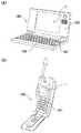
[電子機器への適用]
図7(A)、(B)はそれぞれ、本発明に係るEL表示装置1(電気光学装置)を用いた電子機器の一例としてのモバイル型のパーソナルコンピュータの説明図、および携帯電話機の説明図である。[Application to electronic devices]
7A and 7B are an explanatory diagram of a mobile personal computer as an example of an electronic apparatus using the EL display device 1 (electro-optical device) according to the present invention, and an explanatory diagram of a mobile phone, respectively. is there.
本発明を適用したEL表示装置1を搭載した電子機器としては、マルチメディア対応のパーソナルコンピュータ(PC)、およびエンジニアリング・ワークステーション(EWS)、ページャあるいは携帯電話機、ワードプロセッサ、テレビ、ビューファインダ型またはモニタ直視型のビデオテープレコーダ、電子手帳、カーナビゲーション装置、POS端末、家庭電器機器の表示モニター、ポケットゲーム機器などがある。 The electronic apparatus equipped with the
より具体的には、図7(A)に示すように、パーソナルコンピュータ180は、キーボード181を備えた本体部182と、表示ユニット183とを有する。表示ユニット183は、前述したEL表示装置1を含んで構成される。また、図7(B)に示すように、携帯電話機190は、複数の操作ボタン191と、前述したEL表示装置1からなる表示部とを有している。 More specifically, as shown in FIG. 7A, the
本発明において、マトリクス状に配置された多数の画素では、ソース領域側のチャネル幅寸法とドレイン領域側のチャネル幅寸法が相違する非対称構造のTFTが用いられており、非対称構造のTFTがNチャネル型の場合には、ソース・ドレイン領域のうち、オフ時に高電位側となる方にチャネル幅寸法の小さい方が配置され、非対称構造のTFTがPチャネル型である場合には、ソース・ドレイン領域のうち、オフ時に低電位側となる方にチャネル幅寸法の小さい方が配置されている。このような非対称構造のTFTではオフリーク電流が極めて小さいため、電気光学素子を安定した条件下で駆動することができる。それ故、階調表示を良好に行えるなど、表示の品位を向上することができる。 In the present invention, a large number of pixels arranged in a matrix use an asymmetrical TFT in which the channel width dimension on the source region side and the channel width dimension on the drain region side are different. In the case of the type, of the source / drain regions, the one with the smaller channel width dimension is arranged on the higher potential side when off, and when the TFT with an asymmetric structure is a P-channel type, the source / drain region Of these, the one with the smaller channel width dimension is disposed on the low potential side when turned off. In such an asymmetric TFT, the off-leakage current is extremely small, so that the electro-optic element can be driven under stable conditions. Therefore, display quality can be improved, such as good gradation display.
1 EL表示装置(電気光学装置)、10 基板、11 画素、13 画像表示領域、12 データ線駆動回路、14 走査線駆動回路、20 EL素子(電流駆動型発光素子/電気光学素子)、30 駆動用トランジスタ、40 蓄積容量、50 第1のTFT(第1のスイッチング素子)、60 第2のTFT(第2のスイッチング素子)、70 第3のTFT(第3のスイッチング素子)、100 低温多結晶シリコン膜、110 チャネル領域、120 ソース領域、130 ドレイン領域1 EL display device (electro-optical device), 10 substrate, 11 pixels, 13 image display area, 12 data line driving circuit, 14 scanning line driving circuit, 20 EL element (current-driven light emitting element / electro-optical element), 30 driving Transistor, 40 storage capacitor, 50 first TFT (first switching element), 60 second TFT (second switching element), 70 third TFT (third switching element), 100 low temperature polycrystal Silicon film, 110 channel region, 120 source region, 130 drain region
Claims (16)
Translated fromJapanese前記多数の画素には、前記トランジスタのうちの少なくとも1つに、ソース領域側のチャネル幅寸法とドレイン領域側のチャネル幅寸法が相違する非対称構造の薄膜トランジスタが用いられた複数の画素が含まれていることを特徴とする電気光学装置。In each of a large number of pixels arranged in a matrix, an electro-optical device including at least an electro-optical element and one or more transistors for driving the electro-optical element.
The plurality of pixels include a plurality of pixels in which at least one of the transistors includes a thin film transistor having an asymmetric structure in which a channel width dimension on the source region side and a channel width dimension on the drain region side are different. An electro-optical device.
前記多数の画素は各々、前記トランジスタとして、少なくとも、前記エレクトロルミネッセンス素子に印加する電流を制御する駆動用トランジスタと、前記駆動用トランジスタのゲートに接続された蓄積容量と、前記蓄積容量に直列に接続されて、当該蓄積容量にデータ信号を書き込むタイミングを制御する第1のスイッチング素子とを備え、
前記多数の画素には、前記第1のスイッチング素子として前記非対称構造の薄膜トランジスタが用いられている複数の画素が含まれていることを特徴とする電気光学装置。The current-driven light-emitting element according to claim 5, wherein the current-driven light-emitting element is an electroluminescence element.
Each of the plurality of pixels, as the transistor, includes at least a driving transistor that controls a current applied to the electroluminescence element, a storage capacitor connected to a gate of the driving transistor, and a serial connection to the storage capacitor. And a first switching element that controls the timing of writing a data signal to the storage capacitor,
The electro-optical device, wherein the plurality of pixels includes a plurality of pixels in which the asymmetric thin film transistor is used as the first switching element.
前記第1のスイッチング素子と前記第3のスイッチング素子との電気的な接続点と、前記駆動用トランジスタと前記第2のスイッチング素子との電気的な接続点とが短絡されていることを特徴とする電気光学装置。7. The current flowing through the EL element connected to the driving transistor in series in addition to the driving transistor and the first switching element as each of the plurality of pixels in each of the plurality of pixels. A second switching element for turning on and off, and a third switching element connected in series on the opposite side of the storage capacitor with respect to the first switching element,
An electrical connection point between the first switching element and the third switching element and an electrical connection point between the driving transistor and the second switching element are short-circuited. An electro-optical device.
いずれの色に対応する画素においても、ソース・ドレイン領域のうち、チャネル幅寸法の小さい方が前記蓄積容量の側に接続されているか、チャネル幅寸法の大きい方が前記蓄積容量の側に接続されているかが同一であることを特徴とする電気光学装置。In Claim 6 or 7, as said electroluminescence element, a plurality of kinds of electroluminescence elements corresponding to each color are formed,
In the pixel corresponding to any color, the source / drain region having the smaller channel width dimension is connected to the storage capacitor side or the larger channel width dimension is connected to the storage capacitor side. The electro-optical device is characterized in that they are the same.
ソース・ドレイン領域のうち、チャネル幅寸法の小さい方が前記蓄積容量の側に接続されているか、チャネル幅寸法の大きい方が前記蓄積容量の側に接続されているかが、画素が対応する色によって相違していることを特徴とする電気光学装置。In Claim 6 or 7, as said electroluminescence element, a plurality of kinds of electroluminescence elements corresponding to each color are formed,
Of the source / drain regions, whether the smaller channel width dimension is connected to the storage capacitor side or the larger channel width dimension is connected to the storage capacitor side depends on the color corresponding to the pixel. An electro-optical device characterized by being different.
Priority Applications (1)
| Application Number | Priority Date | Filing Date | Title |
|---|---|---|---|
| JP2003366016AJP4496756B2 (en) | 2003-10-27 | 2003-10-27 | Electro-optical device and electronic apparatus |
Applications Claiming Priority (1)
| Application Number | Priority Date | Filing Date | Title |
|---|---|---|---|
| JP2003366016AJP4496756B2 (en) | 2003-10-27 | 2003-10-27 | Electro-optical device and electronic apparatus |
Publications (2)
| Publication Number | Publication Date |
|---|---|
| JP2005128410Atrue JP2005128410A (en) | 2005-05-19 |
| JP4496756B2 JP4496756B2 (en) | 2010-07-07 |
Family
ID=34644502
Family Applications (1)
| Application Number | Title | Priority Date | Filing Date |
|---|---|---|---|
| JP2003366016AExpired - Fee RelatedJP4496756B2 (en) | 2003-10-27 | 2003-10-27 | Electro-optical device and electronic apparatus |
Country Status (1)
| Country | Link |
|---|---|
| JP (1) | JP4496756B2 (en) |
Citations (9)
| Publication number | Priority date | Publication date | Assignee | Title |
|---|---|---|---|---|
| JPH07263705A (en)* | 1994-03-24 | 1995-10-13 | Sony Corp | Thin film transistor |
| JPH08160469A (en)* | 1994-08-31 | 1996-06-21 | Semiconductor Energy Lab Co Ltd | Liquid crystal display device |
| JP2002124677A (en)* | 2000-10-13 | 2002-04-26 | Nec Corp | Substrate for liquid crystal displays and its manufacturing method |
| JP2002151700A (en)* | 2000-11-15 | 2002-05-24 | Fujitsu Ltd | Thin film transistor |
| JP2003066488A (en)* | 2001-08-30 | 2003-03-05 | Hitachi Ltd | Liquid crystal display |
| JP2003084686A (en)* | 2001-09-12 | 2003-03-19 | Matsushita Electric Ind Co Ltd | Liquid crystal display device and organic EL display device |
| JP2003150118A (en)* | 2001-11-14 | 2003-05-23 | Matsushita Electric Ind Co Ltd | EL display device, driving method thereof, and information display device |
| JP2003197915A (en)* | 2001-12-21 | 2003-07-11 | Sharp Corp | Thin film transistor and liquid crystal display |
| WO2003081676A1 (en)* | 2002-03-25 | 2003-10-02 | Kabushiki Kaisha Ekisho Sentan Gijutsu Kaihatsu Center | Thin film transistor, circuit device and liquid crystal display |
- 2003
- 2003-10-27JPJP2003366016Apatent/JP4496756B2/ennot_activeExpired - Fee Related
Patent Citations (9)
| Publication number | Priority date | Publication date | Assignee | Title |
|---|---|---|---|---|
| JPH07263705A (en)* | 1994-03-24 | 1995-10-13 | Sony Corp | Thin film transistor |
| JPH08160469A (en)* | 1994-08-31 | 1996-06-21 | Semiconductor Energy Lab Co Ltd | Liquid crystal display device |
| JP2002124677A (en)* | 2000-10-13 | 2002-04-26 | Nec Corp | Substrate for liquid crystal displays and its manufacturing method |
| JP2002151700A (en)* | 2000-11-15 | 2002-05-24 | Fujitsu Ltd | Thin film transistor |
| JP2003066488A (en)* | 2001-08-30 | 2003-03-05 | Hitachi Ltd | Liquid crystal display |
| JP2003084686A (en)* | 2001-09-12 | 2003-03-19 | Matsushita Electric Ind Co Ltd | Liquid crystal display device and organic EL display device |
| JP2003150118A (en)* | 2001-11-14 | 2003-05-23 | Matsushita Electric Ind Co Ltd | EL display device, driving method thereof, and information display device |
| JP2003197915A (en)* | 2001-12-21 | 2003-07-11 | Sharp Corp | Thin film transistor and liquid crystal display |
| WO2003081676A1 (en)* | 2002-03-25 | 2003-10-02 | Kabushiki Kaisha Ekisho Sentan Gijutsu Kaihatsu Center | Thin film transistor, circuit device and liquid crystal display |
Also Published As
| Publication number | Publication date |
|---|---|
| JP4496756B2 (en) | 2010-07-07 |
Similar Documents
| Publication | Publication Date | Title |
|---|---|---|
| JP7235907B2 (en) | light emitting device | |
| TWI436334B (en) | Display apparatus | |
| CN1333382C (en) | Current-driven light-emitting display device and manufacturing method thereof | |
| US7215304B2 (en) | Display apparatus in which characteristics of a plurality of transistors are made to differ from one another | |
| US6954194B2 (en) | Semiconductor device and display apparatus | |
| JP4562997B2 (en) | Element substrate and light emitting device | |
| JP5491835B2 (en) | Pixel circuit and display device | |
| JP2004347626A (en) | Element substrate and light emitting device | |
| JP2006215275A (en) | Display apparatus | |
| JP2009169239A (en) | Self-luminous display device and driving method thereof | |
| US20220076617A1 (en) | Pixel and display device including the same | |
| JP2006053539A (en) | Semiconductor device, display device, or display device driving method | |
| JP2005134880A (en) | Image display device, driving method thereof, and precharge voltage setting method | |
| US11705057B2 (en) | Pixel and display apparatus having the same | |
| US11527200B2 (en) | Display device and driving method thereof | |
| JP5109302B2 (en) | Display device and manufacturing method thereof | |
| JP4496756B2 (en) | Electro-optical device and electronic apparatus | |
| JP2005215609A (en) | Unit circuit, electro-optical device and electronic apparatus | |
| JP2010008941A (en) | Pixel circuit and display device | |
| US20230169919A1 (en) | Display apparatus and display panel thereof | |
| JP2009036933A (en) | Active matrix type light emitting display device | |
| US20250209980A1 (en) | Display device and method of driving same | |
| JP4842381B2 (en) | Semiconductor device | |
| JP4192690B2 (en) | Luminescent display device | |
| JP2005031648A (en) | Element substrate and light emitting device |
Legal Events
| Date | Code | Title | Description |
|---|---|---|---|
| A621 | Written request for application examination | Free format text:JAPANESE INTERMEDIATE CODE: A621 Effective date:20060929 | |
| RD04 | Notification of resignation of power of attorney | Free format text:JAPANESE INTERMEDIATE CODE: A7424 Effective date:20070403 | |
| A977 | Report on retrieval | Free format text:JAPANESE INTERMEDIATE CODE: A971007 Effective date:20091126 | |
| A131 | Notification of reasons for refusal | Free format text:JAPANESE INTERMEDIATE CODE: A131 Effective date:20091201 | |
| A521 | Request for written amendment filed | Free format text:JAPANESE INTERMEDIATE CODE: A523 Effective date:20100125 | |
| RD03 | Notification of appointment of power of attorney | Free format text:JAPANESE INTERMEDIATE CODE: A7423 Effective date:20100125 | |
| TRDD | Decision of grant or rejection written | ||
| A01 | Written decision to grant a patent or to grant a registration (utility model) | Free format text:JAPANESE INTERMEDIATE CODE: A01 Effective date:20100323 | |
| A01 | Written decision to grant a patent or to grant a registration (utility model) | Free format text:JAPANESE INTERMEDIATE CODE: A01 | |
| A61 | First payment of annual fees (during grant procedure) | Free format text:JAPANESE INTERMEDIATE CODE: A61 Effective date:20100405 | |
| FPAY | Renewal fee payment (event date is renewal date of database) | Free format text:PAYMENT UNTIL: 20130423 Year of fee payment:3 | |
| R150 | Certificate of patent or registration of utility model | Free format text:JAPANESE INTERMEDIATE CODE: R150 | |
| FPAY | Renewal fee payment (event date is renewal date of database) | Free format text:PAYMENT UNTIL: 20130423 Year of fee payment:3 | |
| FPAY | Renewal fee payment (event date is renewal date of database) | Free format text:PAYMENT UNTIL: 20140423 Year of fee payment:4 | |
| LAPS | Cancellation because of no payment of annual fees |