JP2005124918A - Electric machine-driven artificial heart - Google Patents
Electric machine-driven artificial heartDownload PDFInfo
- Publication number
- JP2005124918A JP2005124918AJP2003365183AJP2003365183AJP2005124918AJP 2005124918 AJP2005124918 AJP 2005124918AJP 2003365183 AJP2003365183 AJP 2003365183AJP 2003365183 AJP2003365183 AJP 2003365183AJP 2005124918 AJP2005124918 AJP 2005124918A
- Authority
- JP
- Japan
- Prior art keywords
- motor
- speed
- artificial heart
- variable volume
- volume chamber
- Prior art date
- Legal status (The legal status is an assumption and is not a legal conclusion. Google has not performed a legal analysis and makes no representation as to the accuracy of the status listed.)
- Granted
Links
- 230000033001locomotionEffects0.000claimsabstractdescription21
- 239000008280bloodSubstances0.000claimsdescription40
- 210000004369bloodAnatomy0.000claimsdescription40
- 230000008602contractionEffects0.000claimsdescription17
- 238000000034methodMethods0.000abstractdescription2
- 230000035939shockEffects0.000abstract1
- 230000000747cardiac effectEffects0.000description22
- 238000006243chemical reactionMethods0.000description11
- 230000017531blood circulationEffects0.000description10
- 238000010586diagramMethods0.000description9
- 230000007423decreaseEffects0.000description7
- 238000001727in vivoMethods0.000description5
- 230000005540biological transmissionEffects0.000description2
- 230000004907fluxEffects0.000description2
- 230000007774longtermEffects0.000description2
- 230000000149penetrating effectEffects0.000description2
- 230000002093peripheral effectEffects0.000description2
- 238000005086pumpingMethods0.000description2
- 238000004088simulationMethods0.000description2
- 210000001015abdomenAnatomy0.000description1
- 210000000709aortaAnatomy0.000description1
- 210000002376aorta thoracicAnatomy0.000description1
- 230000003247decreasing effectEffects0.000description1
- 230000000694effectsEffects0.000description1
- 210000005240left ventricleAnatomy0.000description1
- 230000010349pulsationEffects0.000description1
- 210000000115thoracic cavityAnatomy0.000description1
Images


Landscapes
- Reciprocating Pumps (AREA)
- External Artificial Organs (AREA)
- Prostheses (AREA)
Abstract
Description
Translated fromJapanese本発明は、体内に完全に埋め込まれる電気機械駆動式人工心臓に関し、特に、その耐久性を向上させる技術に関する。 The present invention relates to an electromechanically driven artificial heart that is completely implanted in the body, and more particularly to a technique for improving its durability.
体内完全埋め込み型の人工心臓として、ポンプハウジング内に、モータと、モータのローターと一体化されたナットと、ナットに螺合されるとともに回転不能とされたローラねじと、そのローラねじの先端に固定された押圧板と、押圧板によって駆動させられるダイヤフラムとを備え、ポンプハウジングとダイヤフラムとの間に、血液流入口と血液流出口とを備えた可変容積室が形成されている電気機械駆動式人工心臓が知られている。 As a fully implantable artificial heart, a pump, a nut integrated with the rotor of the motor, a roller screw screwed into the nut and made non-rotatable, and a tip of the roller screw An electromechanical drive type comprising a fixed pressing plate and a diaphragm driven by the pressing plate, and a variable volume chamber having a blood inlet and a blood outlet is formed between the pump housing and the diaphragm. An artificial heart is known.
上記電気機械駆動式人工心臓では、ナットに螺合されたローラねじが回転不能とされていることから、モータが回転させられることによりナットが回転させられると、ローラねじは直線運動し、ローラねじの先端に固定された押圧板がダイヤフラムを押圧するので、可変容積室の容積が小さくなって、可変容積室内の血液が血液流出口から送り出される。そして、モータが逆方向に回転させられると、押圧板がダイヤフラムから離れる方向に移動して、ダイヤフラムは、血液流入口からの血液流入圧およびダイヤフラム自身の弾性復帰力により可変容積室の容積が大きくなる方向に変形するので、血液流入口から可変容積室内へ血液が流入する。なお、この型式の人工心臓には、可変容積室を1つだけ備え、心臓を切除しないで用いる補助人工心臓と、可変容積室を2つ備え、心臓を切除して、2つの可変容積室の交互の拍動により血液循環を維持する全置換型人工心臓とがある。 In the electromechanical artificial heart, the roller screw screwed to the nut is not rotatable. Therefore, when the nut is rotated by rotating the motor, the roller screw linearly moves and the roller screw Since the pressing plate fixed to the tip of the pressing member presses the diaphragm, the volume of the variable volume chamber is reduced, and the blood in the variable volume chamber is sent out from the blood outlet. When the motor is rotated in the reverse direction, the pressing plate moves away from the diaphragm, and the diaphragm has a large volume of the variable volume chamber due to the blood inflow pressure from the blood inlet and the elastic return force of the diaphragm itself. Therefore, blood flows from the blood inlet into the variable volume chamber. This type of artificial heart includes only one variable volume chamber, and includes an auxiliary artificial heart that is used without excising the heart and two variable volume chambers. There is a total replacement artificial heart that maintains blood circulation by alternating pulsations.
一度、人工心臓を体内に埋め込んでしまうと、簡単には取り出せないことから、体内埋め込み式の人工心臓には、長期耐久性が要求される。しかし、上記電気機械駆動式の人工心臓は、従来、ローラねじが最もモータ側の位置で一旦停止する際に生じる衝撃が比較的大きく、また、人工心臓は、一日に平均10万回前後(平均心拍数80拍/分)の収縮、拡張が行われるので、衝撃が繰り返されることによるラジアルベアリング等の機械的負荷が大きい。そのため、これまで、上記電気機械駆動式の人工心臓は機械的耐久性に問題があった。 Once an artificial heart is implanted in the body, it cannot be easily removed. Therefore, a long-term durability is required for an implantable artificial heart. However, the above-mentioned electromechanical artificial heart has hitherto been relatively large in impact when the roller screw stops at the most motor side position, and the artificial heart has an average of about 100,000 times a day ( Since contraction and expansion of an average heart rate of 80 beats / minute are performed, a mechanical load such as a radial bearing due to repeated impact is large. Therefore, heretofore, the electromechanical artificial heart has a problem in mechanical durability.
本発明は、以上の事情を背景として為されたものであり、その目的とするところは、長期耐久性が得られる体内完全埋め込み型の電気機械駆動式人工心臓を提供することにある。 The present invention has been made in the background of the above circumstances, and an object of the present invention is to provide a fully implantable electromechanical drive artificial heart that can achieve long-term durability.
かかる目的を達成する第1発明は、(a)ねじと、そのねじと螺合するナットとを有し、そのナットの回転により、そのナットに対してそのねじが軸方向両側へ相対移動する往復運動装置と、(b)その往復運動装置を駆動させるモータと、(c)そのモータの回転速度を制御する速度制御装置と、(d)血液流入口と血液流出口とを有し、その往復運動装置の往復運動に基づいて収縮、拡張が繰り返される可変容積室とを備えた体内完全埋め込み型の電気機械駆動式人工心臓であって、(e)前記速度制御装置は、前記可変容積室の容積拡張期におけるモータの回転速度を、所定の最高速度とした後、速度0まで連続的に減少させることを特徴とする。 A first invention that achieves such an object includes (a) a screw and a nut that is screwed to the screw, and reciprocating the screw relative to the nut in both axial directions by rotation of the nut. An exercise device, (b) a motor for driving the reciprocation device, (c) a speed control device for controlling the rotational speed of the motor, and (d) a blood inlet and a blood outlet, A fully implantable electromechanical drive artificial heart with a variable volume chamber that repeatedly contracts and expands based on a reciprocating motion of the exercise device, and (e) the speed control device includes the variable volume chamber. The rotational speed of the motor in the volume expansion period is set to a predetermined maximum speed and then continuously reduced to a speed of 0.
また、第2発明は、(a)ねじと、そのねじと螺合するナットとを有し、そのナットの回転により、そのナットに対してそのねじが軸方向両側へ相対移動する往復運動装置と、(b)その往復運動装置を駆動させるモータと、(c)そのモータの回転速度を制御する速度制御装置と、(d)血液流入口と血液流出口とを有し、その往復運動装置の往復運動に基づいて収縮、拡張が繰り返される可変容積室とを備えた体内完全埋め込み型の電気機械駆動式人工心臓であって、(e)前記速度制御装置は、前記可変容積室の容積拡張期における前記モータの回転速度を、所定の最高速度とした後、その最高速度と速度0との間の中間速度を経て、速度0とすることを特徴とする。 Further, the second invention includes (a) a reciprocating motion device having a screw and a nut screwed to the screw, wherein the screw relatively moves in the axial direction with respect to the nut by rotation of the nut. (B) a motor that drives the reciprocating device, (c) a speed control device that controls the rotational speed of the motor, and (d) a blood inlet and a blood outlet, A fully implantable electromechanical drive type artificial heart having a variable volume chamber that repeatedly contracts and expands based on a reciprocating motion, and (e) the speed control device has a volume expansion period of the variable volume chamber After the rotational speed of the motor in (1) is set to a predetermined maximum speed, the speed is set to 0 through an intermediate speed between the maximum speed and 0.
また、第3発明は、第1発明または第2発明の電気機械駆動式人工心臓において、前記速度制御装置は、前記可変容積室の容積拡張時には、前記モータを駆動制御する制御電圧を、所定の最高電圧とし、次いで、その最高電圧よりも低い所定の中間電圧にて所定時間保持した後、0とすることを特徴とする。 According to a third aspect of the present invention, in the electromechanical artificial heart according to the first or second aspect of the invention, the speed control device applies a control voltage for driving and controlling the motor when the volume of the variable volume chamber is expanded. It is characterized in that it is set to the maximum voltage, and then is set to 0 after being held for a predetermined time at a predetermined intermediate voltage lower than the maximum voltage.
また、第4発明は、第1発明乃至第3発明の電気機械駆動式人工心臓において、前記速度制御装置は、前記モータを駆動制御する制御電圧を、前記可変容積室の容積収縮開始時に、前記モータを始動可能な所定の第1電圧値とし、その後は、その可変容積室の容積収縮終了時まで、連続的にまたは段階的に上昇させることを特徴とする。 According to a fourth aspect of the present invention, in the electromechanical artificial heart according to the first to third aspects of the invention, the speed control device applies a control voltage for driving and controlling the motor at the start of volumetric contraction of the variable volume chamber. A predetermined first voltage value at which the motor can be started is set, and thereafter, the voltage is increased continuously or stepwise until the end of volume contraction of the variable volume chamber.
また、第5発明は、第1発明乃至第3発明の電気機械駆動式人工心臓において、前記速度制御装置は、前記モータを駆動制御する制御電圧を、前記可変容積室の容積収縮開始時に、前記モータを始動可能な所定の第1電圧値とし、その後は、その可変容積室の容積収縮終了時まで、上昇率が漸次小さくなる指数関数的に上昇させることを特徴とする。 Further, a fifth invention is the electromechanical drive type artificial heart of the first invention to the third invention, wherein the speed control device applies a control voltage for driving and controlling the motor at the start of volume contraction of the variable volume chamber. A predetermined first voltage value at which the motor can be started is set, and thereafter, the rate of increase is increased exponentially until the volumetric contraction of the variable volume chamber ends.
上記第1発明によれば、可変容積室の容積拡張期における往復運動装置の停止が緩やかになるので、その際の衝撃が減少し、耐久性が向上する。また、衝撃として失われるエネルギーが少なくなるので、人工心臓の効率も向上する。 According to the first aspect of the present invention, the reciprocating device stops gently during the volume expansion period of the variable volume chamber, so that the impact at that time is reduced and the durability is improved. In addition, since the energy lost as an impact is reduced, the efficiency of the artificial heart is also improved.
また、第2発明の場合にも、可変容積室の容積拡張期における往復運動装置の停止が緩やかになるので、その際の衝撃が減少し、耐久性が向上する。また、衝撃として失われるエネルギーが少なくなるので、人工心臓の効率も向上する。 Also in the case of the second invention, since the stop of the reciprocating device during the volume expansion period of the variable volume chamber becomes gentle, the impact at that time is reduced and the durability is improved. In addition, since the energy lost as an impact is reduced, the efficiency of the artificial heart is also improved.
また、第3発明は、モータの回転速度を第1発明または第2発明のように変化させるための制御電圧の一態様であり、第1発明または第2発明と同様の効果が得られる。 The third invention is an aspect of the control voltage for changing the rotation speed of the motor as in the first invention or the second invention, and the same effect as the first invention or the second invention is obtained.
第4発明または第5発明によれば、可変容積室の容積収縮期におけるモータの回転速度が緩やかに最高速度まで上昇することから、その容積収縮開始時のモータ電流にピークがなくなるとともに、収縮期における可変容積室内圧の変化および可変容積室から拍出される血液流量の変化が少なくなるので、人工心臓の効率がさらに向上する。 According to the fourth or fifth invention, since the rotational speed of the motor during the volume contraction period of the variable volume chamber gradually increases to the maximum speed, the motor current at the start of the volume contraction has no peak, and the contraction period. Since the change in the variable volume chamber pressure and the change in the blood flow rate pumped out from the variable volume chamber are reduced, the efficiency of the artificial heart is further improved.
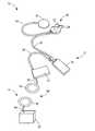
以下、本発明の実施例を図面を参照しつつ詳細に説明する。図1は、本発明が適用された電気機械駆動式の容積置換型補助人工心臓(以下、単に補助人工心臓という)10の全体構造を示す図である。補助人工心臓10は、腹部や胸腔内に埋め込まれる体内埋め込み部12と、体外から体内埋め込み部12に電力を供給する体外部14とからなる。 Hereinafter, embodiments of the present invention will be described in detail with reference to the drawings. FIG. 1 is a diagram showing the entire structure of an electromechanical drive type volume replacement type auxiliary artificial heart (hereinafter simply referred to as an auxiliary artificial heart) 10 to which the present invention is applied. The auxiliary
体内埋め込み部12は、心臓補助ポンプ20、速度制御装置70、体内バッテリー72、体積補償装置74、および二次コイル76を備え、心臓補助ポンプ20と速度制御装置70、速度制御装置70と体内バッテリー72、体内バッテリー72と二次コイル76が、それぞれ配線78、80、82で接続され、心臓補助ポンプ20と体積補償装置74とが配管84により接続された構造を有している。一方、体外部14は、外部バッテリー90と一次コイル92とを有し、それら外部バッテリー90と一次コイル92とが配線94により接続された構造である。 The
心臓補助ポンプ20は血液流入口22および血液流出口24を備えており、一方の端が血液流入口22に接続される図示しないチューブの他端が左心室に挿入され、一方の端が血液流出口24に接続される図示しないチューブの他端が上行大動脈や下行大動脈などに接続される。 The
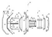
図2は、心臓補助ポンプ20の分解断面図である。図2に示すように、心臓補助ポンプ20は、ハウジング26と、ダイヤフラム28と、押圧板として機能するプッシャープレート29と、回転−直線運動変換装置30と、ナット31と、モータコイル(ステータ)40と、ロータ44と、バックプレート34とを備えている。 FIG. 2 is an exploded sectional view of the
ハウジング26には、前記血液流入口22および血液流出口24(血液流出口24は図2には図示せず)が形成されており、血液流入口22には、血液流入口22からハウジング26内に血液が流入する際には開くが、血液流出口24から血液が流出する際には閉じる逆止弁36が設けられている。また、図示しないが、血液流出口24には、血液流出口24から血液が流出する際には開くが、血液流入口22からハウジング26内に血液が流入する際には閉じる逆止弁が設けられている。 The
モータコイル40およびロータ44を備えているモータ32は、本実施例では3相のブラシレスDCモータである。モータハウジング38は、リング状であり、エンドベル48およびモータホルダー50は、それぞれ大径側がモータハウジング38に当接させられている。これらモータハウジング38、エンドベル48、およびモータホルダー50により形成される空間内に、モータコイル40、ベアリング42、ロータ44、およびナット31などが収容されており、モータコイル40は、モータハウジング38に固定されている。また、ロータ44とナット31とは一体化させられており、それらロータ44およびナット31は、一対のベアリング42を介してモータコイル40に回転可能に支持されている。 The
回転−直線運動変換装置30は、外周面にナット31と螺合するねじ山が形成されたローラねじ52を有している。ローラねじ52は円盤状部材54の中心に、その円盤状部材54に対して垂直に固定されている。円盤状部材54には、ローラねじ52と平行となるようにモータ32方向に突き出す鉤部54aが一対形成されており、その一対の鉤部54aに、ローラねじ52と平行となるようにスライドシャフト56が固定されている。このスライドシャフト56は、エンドベル48に形成され軸方向に貫通する案内穴58およびモータハウジング38に形成された案内穴59に挿し通されるので、回転−直線運動変換装置30はモータ32に対して相対回転不能となっている。このように構成された回転−直線運動変換装置30とナット31とにより往復運動装置が構成され、ロータ44の回転によりナット31が回転させられると、モータ32に対して相対回転不能とされたローラねじ52が軸方向に移動させられるとともに、スライドシャフト56が案内穴58、59によりその軸方向に案内されるので、回転−直線運動変換装置30は軸方向に運動する。 The rotation-linear
上記ローラねじ52には軸方向に貫通する貫通穴60が形成されている。その貫通穴60には、円盤状部材54aを介して、プッシャープレート29に固定されたピン62が挿入されている。 The
ダイヤフラム28は、伸縮性のある柔らかい膜であり、その大半がプッシャープレート29により支持されているとともに、その外周縁がハウジング26とモータハウジング38とにより挟持されている。このダイヤフラム28とハウジング26との間に、可変容積室64が形成される。 The
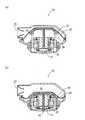
図3は、このように構成された心臓補助ポンプ20の駆動状態を示す図である。モータ32によりナット31が回転させられると、回転−直線運動変換装置30およびその回転−直線運動変換装置30に一体化されたプッシャープレート29がモータ32の軸心方向に移動させられ、モータ32によるナット31の回転により、プッシャープレート29がダイヤフラム28を押圧する方向に移動させられると、図3(a)に示すように、可変容積室64の容積は減少し、血液流出口24(図3には図示せず)から血液が駆出される。一方、モータ32がそれとは逆方向に回転させられると、図3(b)に示すように、回転−直線運動変換装置30がダイヤフラム28およびプッシャープレート29から離れる方向に移動させられ、ダイヤフラム28の弾性復帰力および血液の流入圧により、可変容積室64の容積は増加し、血液流入口22から血液が可変容積室64内に流入する。なお、以下、可変容積室64の容積減少期間を収縮期といい、容積増加期間を拡張期という。 FIG. 3 is a diagram illustrating a driving state of the
図1に戻って、速度制御装置70は、心臓補助ポンプ20のモータ32におけるナット31の回転速度を予め設定された速度制御パターンで制御するとともに、モータ32におけるナット31の回転方向を制御する。体内バッテリー72は、体外からの電力供給が一時的に途絶えたりした時、一時的に速度制御装置70および心臓補助ポンプ20に電力を供給するものであり、40分〜1時間、それら速度制御装置70および心臓補助ポンプ20を駆動できる。体積補償装置74は、配管84により心臓補助ポンプ20内の可変容積室64以外の空間と連通させられており、体内に埋め込まれた時、可変容積室64の容積増加/減少に対応して、その容積が減少/増加させられ、心臓補助ポンプ20内の可変容積室64以外の空間に陽圧や陰圧が発生しないようにするものである。 Returning to FIG. 1, the
生体内に埋め込まれる二次コイル76および体外部14の一次コイル92は、ともに、電力伝送コイルを内部に有しており、それら二次コイル76と一次コイル92とにより、経皮伝送装置96が構成される。一次コイル92を二次コイル76に近づけた状態で、外部バッテリー90からの電力により一次コイル92に電流が流されると、一次コイル92に磁束が発生し、その磁束により、二次コイル76に誘導起電力が発生させられ、さらに、整流器を通して交流(AC)から直流(DC)に変換されて、体内バッテリー72が充電される。 Both the
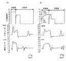
次に、本発明と従来例との比較を説明する。図4は、モータ32を駆動制御するための速度制御装置70の制御電圧CV(上段)、その制御電圧CVに基づいて回転させられるモータ32におけるナット31の回転速度(下段)、モータ32の回転運動により直線運動させられるローラねじ52の位置(中段)を示す図であり、(a)が従来の場合、(b)が本発明の場合を示している。なお、ローラねじ52の位置は、最もモータ32側の位置を0としている。 Next, a comparison between the present invention and a conventional example will be described. FIG. 4 shows the control voltage CV (upper stage) of the
図4に示すように、従来は、制御電圧CVを矩形的に変化させていた。すなわち、収縮期になると制御電圧CVを瞬時に所定の収縮期目標電圧値(図4では約5V)とし、その収縮期目標電圧値を収縮期の終了まで維持し、一旦、瞬時に0Vとした後、拡張期には、再び、瞬時に所定の拡張期目標電圧値(図4では4V弱)とし、その拡張期目標電圧値を所定の時間維持した後に、瞬時に0Vとしていた。このように制御電圧CVを変化させているので、収縮期間中のモータ32の回転速度、および拡張期間中のモータ32の回転速度は、それぞれほぼ一定であり、ローラねじ52の位置は、直線的に変化していた。 As shown in FIG. 4, conventionally, the control voltage CV has been changed in a rectangular manner. That is, at the systole, the control voltage CV is instantaneously set to a predetermined systolic target voltage value (about 5 V in FIG. 4), the systolic target voltage value is maintained until the end of the systole, and temporarily set to 0 V. Later, in the diastole, the predetermined diastole target voltage value (a little less than 4V in FIG. 4) was instantaneously set again, and after maintaining the diastole target voltage value for a predetermined time, it was instantaneously set to 0V. Since the control voltage CV is changed in this way, the rotation speed of the
一方、本発明の場合、制御電圧CVを以下のように変化させる。すなわち、まず、瞬時に、モータ32を回転開始可能な所定の第1電圧値CV1(図4では約2V)とした後、収縮期の終わりまで、上昇率が漸次小さくなる指数関数(たとえば、式1に示す指数関数)に従って連続的に増加させ、収縮期の終わりに所定の第2電圧値CV2(図4では約4V)とし、一旦、瞬時に0Vとする。
(式1) CV=a(1−e−bt)
tは時間、a、bは正の定数である。On the other hand, in the present invention, the control voltage CV is changed as follows. That is, first, an exponential function (for example, a formula in which the rate of increase gradually decreases until the end of systole, after instantaneously setting a predetermined first voltage value CV1 (about 2 V in FIG. 4) at which the
(Formula 1) CV = a (1-e−bt )
t is time, and a and b are positive constants.
そして、拡張期には、まず、サージ電流を防止することができる程度の比較的短い時間だけ0Vを維持した後、瞬時に上記第1電圧値CV1とし、次いで、収縮期に制御電圧CVが第1電圧値CV1から第2電圧値CV2まで増加させられる期間よりも短い期間で前記第2電圧値CV2と同程度の所定の第3電圧値(最高電圧)CV3となるように、且つ、変化率が次第に小さくなるように、連続的に増加させる。次いで、瞬時に、前記第1電圧値CV1と同程度であり、第3電圧値CV3より低く0Vより高い中間電圧として予め設定された第4電圧値CV4まで低下させ、その第4電圧値CV4を、モータ32の回転速度が0となるのに要する時間として設定された所定時間だけ維持した後、瞬時に0Vとする。 In the diastole, first, 0 V is maintained for a relatively short time that can prevent the surge current, and then the first voltage value CV1 is instantaneously set. Then, in the systole, the control voltage CV is changed to the first voltage value CV1. The rate of change is such that a predetermined third voltage value (maximum voltage) CV3 comparable to the second voltage value CV2 is reached in a period shorter than the period during which the voltage value CV1 is increased from the first voltage value CV1 to the second voltage value CV2. Is continuously increased so that becomes gradually smaller. Next, the voltage is instantaneously reduced to a fourth voltage value CV4 which is approximately the same as the first voltage value CV1 and is preset as an intermediate voltage lower than the third voltage value CV3 and higher than 0V, and the fourth voltage value CV4 is decreased. Then, after maintaining for a predetermined time set as the time required for the rotation speed of the
このように制御電圧CVを変化させると、モータ32の回転速度は、収縮期の開始時から連続的に増加していき、収縮期の終了時には、次第に減速する。そして、拡張期には、収縮期とは逆方向に連続的に増加していき、最高速度がしばらく維持された後、速度0まで連続的に減少する。また、ローラねじ52の位置は、再始動開始時の変化および停止時の変化が緩やかになる。 When the control voltage CV is changed in this way, the rotation speed of the
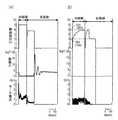
図5は、モータ32の制御電圧CV(上段)、衝撃力の変化(中段)、モータ電流の変化(下段)を示す図であり、(a)が従来の場合、(b)が本発明の場合を示している。なお、衝撃力は、心臓補助ポンプ20のバックプレート34にリングタイプのロードセルを当接させて測定した。 FIG. 5 is a diagram showing a control voltage CV (upper stage), a change in impact force (middle stage), and a change in motor current (lower stage) of the
図5に示すように、従来のように制御電圧CVを制御すると、拡張期において制御電圧CVが瞬時に0Vとされた後、すなわち、回転−直線運動変換装置30が停止させられた後に、衝撃が発生していることが分かる。一方、本発明のように制御電圧CVを制御すると、収縮期および拡張期を通じて、衝撃はほとんど生じていないことが分かる。また、従来のように制御電圧CVを制御すると、収縮期の開始時に、モータ電流に大きなピークが見られるが、本発明の場合には、そのようなピークは見られず、また、本発明の場合には、拡張期において制御電圧CVが第3電圧値CV3から第4電圧値CV4へ低下させられると、モータ電流がほぼ0となっている。 As shown in FIG. 5, when the control voltage CV is controlled as in the prior art, after the control voltage CV is instantaneously set to 0 V in the expansion period, that is, after the rotation-linear
図6は、後負荷に対するポンプ効率の変化を、従来の制御と本発明の制御とで比較した結果を示す図であり、実線が本発明の場合、破線が従来の場合を示す。なお、ポンプ効率は、補助人工心臓10の外的仕事量を入力電力で割った値に所定の係数を掛けた値であり、外的仕事量は、後負荷に対する拍出量(すなわち収縮期の血液流出量)を意味し、後負荷とは、血液流出口24に接続されているチューブの内圧を意味している。図6に示すように、本発明の場合の方が、平均して、2〜3%効率が向上していることが分かる。 FIG. 6 is a diagram showing the result of comparing the change in pump efficiency with respect to the afterload between the conventional control and the control of the present invention, where the solid line indicates the present invention and the broken line indicates the conventional case. The pump efficiency is a value obtained by dividing the external work amount of the auxiliary
図7は、モータ32の制御電圧CV(上段)、心臓補助ポンプ20における可変容積室64の内圧の変化(中段)、心臓補助ポンプ20の血液拍出流量の変化(下段)を示す図であり、(a)が従来の場合、(b)が本発明の場合を示している。図7に示されるように、本発明の場合には、従来の場合に比較して、ポンプ内圧波形およびポンプ流量波形の収縮期における変化が滑らかになっていることが分かる。 FIG. 7 is a diagram showing a control voltage CV of the motor 32 (upper stage), a change in the internal pressure of the
図8は、模擬回路により生体内環境に近い環境とした状態にて駆動させた補助人工心臓10の耐久試験結果を示す図である。なお、この耐久試験は、後負荷を100mmHgとし、毎分平均流量を4.5mL/minとして行った。本発明の補助人工心臓10は約3カ月の連続運転が可能であり、また、入力電力は約4ワットを維持し、ポンプ効率は20%前後であった。 FIG. 8 is a diagram showing a durability test result of the auxiliary
上述の実施例によれば、可変容積室64の容積拡張期において、回転−直線運動変換装置30の停止が緩やかになるので、その際の衝撃が減少し、耐久性が向上する。また、衝撃が減少するので、騒音などによる患者の負担も減少する。また、衝撃として失われるエネルギーが少なくなるので、熱損失による温度上昇が抑えられ補助人工心臓10の効率も向上する。 According to the above-described embodiment, since the rotation-linear
また、本実施例によれば、可変容積室64の容積収縮期におけるモータ32の回転速度が緩やかに最高速度まで上昇することから、可変容積室64の容積収縮開始時のモータ電流にピークがなくなるとともに、収縮期における可変容積室64の内圧の変化および可変容積室64から拍出される血液流量の変化が少なくなるので、補助人工心臓10の効率がさらに向上する。 In addition, according to the present embodiment, the rotational speed of the
以上、本発明の実施例を図面に基づいて詳細に説明したが、本発明はその他の態様においても適用される。 As mentioned above, although the Example of this invention was described in detail based on drawing, this invention is applied also in another aspect.
たとえば、前述の実施例では、拡張期において、モータ32の回転速度が最高速度となった後、速度0まで連続的に減少するように、制御電圧CVを変化させていたが、段階的に(階段状に)モータ32の回転速度が減少するように制御電圧CVを変化させてもよい。 For example, in the above-described embodiment, the control voltage CV is changed so as to continuously decrease to the
また、前述の実施例では、ナット31がモータ32のロータ44と一体化させられるとともに、回転−直線運動変換装置30がモータ32に対して相対回転不能とされることにより、回転−直線運動変換装置30が直線運動するようになっていたが、ねじがモータのロータと一体化させられ、ナットがモータに対して相対回転不能とされることにより、ナットが直線運動するようになっていてもよい。 In the above-described embodiment, the
また、前述の実施例は、本発明を補助人工心臓に適用した例であったが、本発明は、全置換型の電気機械式人工心臓にも適用できる。図9は、全置換型の電気機械式人工心臓に備えられるポンプ100の分解断面図であり、図10は、そのポンプ100の駆動状態を示す図である。なお、図9、10において、前述の実施例と同一の機能を有する部材には、同一の符号を付してある。 Moreover, although the above-mentioned Example was an example which applied this invention to the auxiliary artificial heart, this invention is applicable also to a total replacement type electromechanical artificial heart. FIG. 9 is an exploded cross-sectional view of the
ポンプ100は、可変容積室64を2つ有する点において前述の実施例の心臓補助ポンプ20と異なるが、その2つの可変容積室64の拡張・収縮は、前述の実施例の心臓補助ポンプ20と同様に、1つのナット31およびローラねじ52により行われる。すなわち、ナット31を有する回転部102の両方向の回転により、ローラねじ52がその軸方向の両側に移動するようになっており、そのローラねじ52の移動により、左右いずれか一方のダイヤフラム29が押され、他方のダイヤフラム29の押圧が弱められるようになっている。図10(a)に示すように、ローラねじ52がナット31から左側に突き出す方向に移動させられると、左側の可変容積室64が収縮させられるとともに、右側の可変容積室64が拡張させられるので、矢印で示すように、左側の可変容積室64から血液が拍出され、右側の可変容積室64へ血液が流入する。一方、図10(b)に示すように、ローラねじ52がそれとは反対方向に移動させられると、左側の可変容積室64が収縮させられるとともに、右側の可変容積室64が拡張させられるので、矢印で示すように、左側の可変容積室64に血液が流入するとともに、右側の可変容積室64から血液が拍出される。 The
なお、上述したのはあくまでも一実施形態であり、本発明は当業者の知識に基づいて種々の変更、改良を加えた態様で実施することができる。 The above description is only an embodiment, and the present invention can be implemented in variously modified and improved forms based on the knowledge of those skilled in the art.
10:補助人工心臓、20:心臓補助ポンプ、22:血液流入口、24:血液流出口、30:回転−直線運動変換装置、31:ナット、32:モータ、64:可変容積室、70:速度制御装置10: Auxiliary artificial heart, 20: Cardiac assist pump, 22: Blood inlet, 24: Blood outlet, 30: Rotary-linear motion converter, 31: Nut, 32: Motor, 64: Variable volume chamber, 70: Speed Control device
Claims (5)
Translated fromJapanese該往復運動装置を駆動させるモータと、
該モータの回転速度を制御する速度制御装置と、
血液流入口と血液流出口とを有し、該往復運動装置の往復運動に基づいて収縮、拡張が繰り返される可変容積室と
を備えた体内完全埋め込み型の電気機械駆動式人工心臓であって、
前記速度制御装置は、前記可変容積室の容積拡張期におけるモータの回転速度を、所定の最高速度とした後、速度0まで連続的に減少させることを特徴とする電気機械駆動式人工心臓。A reciprocating device having a screw and a nut screwed with the screw, and rotating the nut relative to the nut in both axial directions;
A motor for driving the reciprocating device;
A speed control device for controlling the rotational speed of the motor;
A fully implantable electromechanically driven artificial heart having a blood inlet and a blood outlet, and a variable volume chamber that repeatedly contracts and expands based on the reciprocating motion of the reciprocating device,
The electromechanical artificial heart according to claim 1, wherein the speed control device continuously reduces the rotational speed of the motor during the volume expansion period of the variable volume chamber to a predetermined maximum speed and then to a speed of zero.
該往復運動装置を駆動させるモータと、
該モータの回転速度を制御する速度制御装置と、
血液流入口と血液流出口とを有し、該往復運動装置の往復運動に基づいて収縮、拡張が繰り返される可変容積室と
を備えた体内完全埋め込み型の電気機械駆動式人工心臓であって、
前記速度制御装置は、前記可変容積室の容積拡張期における前記モータの回転速度を、所定の最高速度とした後、該最高速度と速度0との間の中間速度を経て、速度0とすることを特徴とする電気機械駆動式人工心臓。A reciprocating device having a screw and a nut screwed with the screw, and rotating the nut relative to the nut in both axial directions;
A motor for driving the reciprocating device;
A speed control device for controlling the rotational speed of the motor;
A fully implantable electromechanically driven artificial heart having a blood inlet and a blood outlet, and a variable volume chamber that repeatedly contracts and expands based on the reciprocating motion of the reciprocating device,
The speed control device sets the rotational speed of the motor during the volume expansion period of the variable volume chamber to a predetermined maximum speed, and then sets the speed to 0 through an intermediate speed between the maximum speed and the speed 0. An electromechanical artificial heart characterized by.
Priority Applications (1)
| Application Number | Priority Date | Filing Date | Title |
|---|---|---|---|
| JP2003365183AJP4257418B2 (en) | 2003-10-24 | 2003-10-24 | Electromechanical artificial heart |
Applications Claiming Priority (1)
| Application Number | Priority Date | Filing Date | Title |
|---|---|---|---|
| JP2003365183AJP4257418B2 (en) | 2003-10-24 | 2003-10-24 | Electromechanical artificial heart |
Publications (2)
| Publication Number | Publication Date |
|---|---|
| JP2005124918Atrue JP2005124918A (en) | 2005-05-19 |
| JP4257418B2 JP4257418B2 (en) | 2009-04-22 |
Family
ID=34643943
Family Applications (1)
| Application Number | Title | Priority Date | Filing Date |
|---|---|---|---|
| JP2003365183AExpired - LifetimeJP4257418B2 (en) | 2003-10-24 | 2003-10-24 | Electromechanical artificial heart |
Country Status (1)
| Country | Link |
|---|---|
| JP (1) | JP4257418B2 (en) |
Cited By (2)
| Publication number | Priority date | Publication date | Assignee | Title |
|---|---|---|---|---|
| KR100968242B1 (en) | 2008-01-08 | 2010-07-06 | 고려대학교 산학협력단 | Blood pump driver and blood pump system having same |
| CN102872486A (en)* | 2009-10-23 | 2013-01-16 | 杨碧波 | Cardiac impulse assist system |
- 2003
- 2003-10-24JPJP2003365183Apatent/JP4257418B2/ennot_activeExpired - Lifetime
Cited By (2)
| Publication number | Priority date | Publication date | Assignee | Title |
|---|---|---|---|---|
| KR100968242B1 (en) | 2008-01-08 | 2010-07-06 | 고려대학교 산학협력단 | Blood pump driver and blood pump system having same |
| CN102872486A (en)* | 2009-10-23 | 2013-01-16 | 杨碧波 | Cardiac impulse assist system |
Also Published As
| Publication number | Publication date |
|---|---|
| JP4257418B2 (en) | 2009-04-22 |
Similar Documents
| Publication | Publication Date | Title |
|---|---|---|
| US10799625B2 (en) | Systems and methods for controlling an implantable blood pump | |
| US8167593B2 (en) | System and method for pump with deformable bearing surface | |
| US8386040B2 (en) | System and method for pump variable stroke | |
| US20100268333A1 (en) | System and method for controlling pump | |
| US20150151032A1 (en) | Speed change algorithim for a continuous flow blood pump | |
| US8366401B2 (en) | Positive displacement pump system and method with rotating valve | |
| US11191946B2 (en) | Implantable blood pumps comprising a linear bearing | |
| JP2012514709A (en) | Physiological control method of continuous flow type total replacement artificial heart | |
| US12383722B2 (en) | Next generation total artificial heart | |
| JP4257418B2 (en) | Electromechanical artificial heart | |
| Weiss et al. | Permanent circulatory support systems at the Pennsylvania State University | |
| US20240207599A1 (en) | Next generation total artificial heart system | |
| Altieri | Status of implantable energy systems to actuate and control ventricular assist devices | |
| CN102671248A (en) | Implantable bionic flexible pulsatile pump | |
| Okamoto et al. | Development of a Compact, Highly Efficient, Totally Implantable Motor–Driven Assist Pump System | |
| US12427299B1 (en) | Pulsatile ventricular assist devices | |
| Nakamura et al. | Motor-driven, computer-controlled implantable cardiac assist device—An optical encoder for feedback control | |
| Nakamura et al. | Electromechanically driven, computer-controlled implantable cardiac assist device | |
| WO2004112868A1 (en) | Artificial heart muscle device | |
| Nakamura¹ et al. | 11. Electromechanically driven, computer-controlled implantable cardiac |
Legal Events
| Date | Code | Title | Description |
|---|---|---|---|
| RD03 | Notification of appointment of power of attorney | Free format text:JAPANESE INTERMEDIATE CODE: A7423 Effective date:20050209 | |
| A521 | Request for written amendment filed | Free format text:JAPANESE INTERMEDIATE CODE: A821 Effective date:20050210 | |
| A711 | Notification of change in applicant | Free format text:JAPANESE INTERMEDIATE CODE: A711 Effective date:20061003 | |
| A621 | Written request for application examination | Free format text:JAPANESE INTERMEDIATE CODE: A621 Effective date:20061004 | |
| A521 | Request for written amendment filed | Free format text:JAPANESE INTERMEDIATE CODE: A821 Effective date:20061003 | |
| A977 | Report on retrieval | Free format text:JAPANESE INTERMEDIATE CODE: A971007 Effective date:20080822 | |
| A131 | Notification of reasons for refusal | Free format text:JAPANESE INTERMEDIATE CODE: A131 Effective date:20080826 | |
| A521 | Request for written amendment filed | Free format text:JAPANESE INTERMEDIATE CODE: A523 Effective date:20081022 | |
| TRDD | Decision of grant or rejection written | ||
| A01 | Written decision to grant a patent or to grant a registration (utility model) | Free format text:JAPANESE INTERMEDIATE CODE: A01 Effective date:20090106 | |
| A01 | Written decision to grant a patent or to grant a registration (utility model) | Free format text:JAPANESE INTERMEDIATE CODE: A01 | |
| R150 | Certificate of patent or registration of utility model | Ref document number:4257418 Country of ref document:JP Free format text:JAPANESE INTERMEDIATE CODE: R150 Free format text:JAPANESE INTERMEDIATE CODE: R150 | |
| EXPY | Cancellation because of completion of term |