JP2005123908A - Imaging device - Google Patents
Imaging deviceDownload PDFInfo
- Publication number
- JP2005123908A JP2005123908AJP2003356927AJP2003356927AJP2005123908AJP 2005123908 AJP2005123908 AJP 2005123908AJP 2003356927 AJP2003356927 AJP 2003356927AJP 2003356927 AJP2003356927 AJP 2003356927AJP 2005123908 AJP2005123908 AJP 2005123908A
- Authority
- JP
- Japan
- Prior art keywords
- image
- operating state
- display screen
- information
- additional information
- Prior art date
- Legal status (The legal status is an assumption and is not a legal conclusion. Google has not performed a legal analysis and makes no representation as to the accuracy of the status listed.)
- Granted
Links
Images


Classifications
- H—ELECTRICITY
- H04—ELECTRIC COMMUNICATION TECHNIQUE
- H04M—TELEPHONIC COMMUNICATION
- H04M1/00—Substation equipment, e.g. for use by subscribers
- H04M1/02—Constructional features of telephone sets
- H04M1/0202—Portable telephone sets, e.g. cordless phones, mobile phones or bar type handsets
- H04M1/0206—Portable telephones comprising a plurality of mechanically joined movable body parts, e.g. hinged housings
- H04M1/0208—Portable telephones comprising a plurality of mechanically joined movable body parts, e.g. hinged housings characterized by the relative motions of the body parts
- H04M1/0225—Rotatable telephones, i.e. the body parts pivoting to an open position around an axis perpendicular to the plane they define in closed position
- H—ELECTRICITY
- H04—ELECTRIC COMMUNICATION TECHNIQUE
- H04M—TELEPHONIC COMMUNICATION
- H04M1/00—Substation equipment, e.g. for use by subscribers
- H04M1/02—Constructional features of telephone sets
- H04M1/0202—Portable telephone sets, e.g. cordless phones, mobile phones or bar type handsets
- H04M1/0206—Portable telephones comprising a plurality of mechanically joined movable body parts, e.g. hinged housings
- H04M1/0241—Portable telephones comprising a plurality of mechanically joined movable body parts, e.g. hinged housings using relative motion of the body parts to change the operational status of the telephone set, e.g. switching on/off, answering incoming call
- H04M1/0245—Portable telephones comprising a plurality of mechanically joined movable body parts, e.g. hinged housings using relative motion of the body parts to change the operational status of the telephone set, e.g. switching on/off, answering incoming call using open/close detection
- H—ELECTRICITY
- H04—ELECTRIC COMMUNICATION TECHNIQUE
- H04N—PICTORIAL COMMUNICATION, e.g. TELEVISION
- H04N23/00—Cameras or camera modules comprising electronic image sensors; Control thereof
- H04N23/60—Control of cameras or camera modules
- H04N23/63—Control of cameras or camera modules by using electronic viewfinders
- H04N23/631—Graphical user interfaces [GUI] specially adapted for controlling image capture or setting capture parameters
- H04N23/632—Graphical user interfaces [GUI] specially adapted for controlling image capture or setting capture parameters for displaying or modifying preview images prior to image capturing, e.g. variety of image resolutions or capturing parameters
- H—ELECTRICITY
- H04—ELECTRIC COMMUNICATION TECHNIQUE
- H04N—PICTORIAL COMMUNICATION, e.g. TELEVISION
- H04N23/00—Cameras or camera modules comprising electronic image sensors; Control thereof
- H04N23/60—Control of cameras or camera modules
- H04N23/63—Control of cameras or camera modules by using electronic viewfinders
- H04N23/633—Control of cameras or camera modules by using electronic viewfinders for displaying additional information relating to control or operation of the camera
- H—ELECTRICITY
- H04—ELECTRIC COMMUNICATION TECHNIQUE
- H04M—TELEPHONIC COMMUNICATION
- H04M1/00—Substation equipment, e.g. for use by subscribers
- H04M1/72—Mobile telephones; Cordless telephones, i.e. devices for establishing wireless links to base stations without route selection
- H04M1/724—User interfaces specially adapted for cordless or mobile telephones
- H04M1/72403—User interfaces specially adapted for cordless or mobile telephones with means for local support of applications that increase the functionality
- H—ELECTRICITY
- H04—ELECTRIC COMMUNICATION TECHNIQUE
- H04M—TELEPHONIC COMMUNICATION
- H04M2250/00—Details of telephonic subscriber devices
- H04M2250/52—Details of telephonic subscriber devices including functional features of a camera
Landscapes
- Engineering & Computer Science (AREA)
- Signal Processing (AREA)
- Multimedia (AREA)
- Human Computer Interaction (AREA)
- Studio Devices (AREA)
- Telephone Set Structure (AREA)
- Indication In Cameras, And Counting Of Exposures (AREA)
- Telephone Function (AREA)
Abstract
Translated fromJapaneseDescription
Translated fromJapanese本発明は、静止画や動画の撮像を行う撮像装置、ならびに、撮像機能を有する携帯電話に関するものである。 The present invention relates to an imaging device that captures still images and moving images, and a mobile phone having an imaging function.
従来、比較的高機能なカメラには、カメラ撮影に関わる各種の情報(シャッタ速度や露出補正量、撮影枚数など)を表示するために、LCD(liquid crystal display)などの小型の表示デバイスが用いられている。
例えば特許文献1は、そのような情報を表示用の液晶表示部を備えたカメラに関する技術が記載されている。Conventionally, a relatively high-performance camera uses a small display device such as an LCD (liquid crystal display) to display various information related to camera shooting (shutter speed, exposure compensation amount, number of shots, etc.). It has been.
For example, Patent Document 1 describes a technique related to a camera including a liquid crystal display unit for displaying such information.
一方、プロセッサの処理能力の向上や低消費電力技術の進展に伴って、携帯電話やPDAなどの携帯型の電子機器がますます高機能化しており、静止画や動画の撮像機能を有する携帯電話は今や常識になっている。このような撮像機能付きの携帯電話においても、各種の情報を撮像画像とともに表示するためにLCD等の表示デバイスが利用されている。 On the other hand, mobile electronic devices such as mobile phones and PDAs have become more sophisticated with improvements in processor processing power and progress in low-power consumption technologies, and mobile phones with the ability to capture still images and videos. Is now common sense. In such a mobile phone with an imaging function, a display device such as an LCD is used to display various types of information together with the captured image.
ところで、近年の携帯電話は、表示部とキー入力部とがそれぞれ別の筐体に配置されたものが多い。この種の携帯電話は、一般的な操作スタイルとして、2つの筐体が折り畳まれてキー入力部が内側に隠れる状態(クローズ状態)と、キー入力部および表示部が共に露出する状態(オープン状態)とを有している。 By the way, many recent mobile phones have a display unit and a key input unit arranged in separate housings. In this type of mobile phone, as a general operation style, two cases are folded and the key input part is hidden inside (closed state), and the key input part and the display part are both exposed (open state). ).
また、こうした2筐体型の構造には、一般に、クローズ状態において表示部が内側に隠れるタイプと外側に露出したままのタイプとがある。
前者のタイプには、例えば、表示部の面とキー入力部の面とが向き合った状態で内側に折り畳まれるタイプがある。後者のタイプには、例えば、表示部の面とキー入力部の面とをほぼ平行な状態で相対的に回転させる機構を有し、クローズ状態において、表示部の筐体の下にキー入力部の面が隠れるタイプがある。In addition, there are generally two types of such a two-casing type structure in which the display unit is hidden on the inner side in the closed state and a type in which the display unit is exposed on the outer side.
The former type includes, for example, a type that is folded inward with the surface of the display unit and the surface of the key input unit facing each other. The latter type has, for example, a mechanism that relatively rotates the surface of the display unit and the surface of the key input unit in a substantially parallel state, and in the closed state, the key input unit is placed under the casing of the display unit. There is a type that hides the face.
後者のタイプでは、オープン状態およびクローズ状態の何れにおいても表示部が使用可能であるため、通常は、カメラの撮影も両方の操作スタイルにおいて実行可能である。 In the latter type, since the display unit can be used in both the open state and the closed state, the camera can usually be photographed in both operation styles.
両方の操作スタイルにおいて撮影を行う場合、使用者の筐体の持ち方もこれに合わせて変更した方がカメラとして操作し易いことがある。
すなわち、オープン状態ではキー入力部が使用可能になるため、片手での使用を考えると、キー入力部の筐体を把持した状態で撮影を行えることが好ましい。一方、クローズ状態ではキー入力部が使用不能になるため、多くの場合、オープン状態とは別のシャッタ・ボタンを使用する必要がある。したがって、クローズ状態用のシャッタ・ボタンの配置によっては、筐体の持ち方を変更した方がカメラとして使い易くなる。When shooting in both operation styles, it may be easier to operate as a camera if the user's way of holding the case is changed accordingly.
That is, since the key input unit can be used in the open state, it is preferable that shooting can be performed with the casing of the key input unit held in consideration of use with one hand. On the other hand, since the key input unit cannot be used in the closed state, it is often necessary to use a shutter button different from the open state. Therefore, depending on the arrangement of the shutter button for the closed state, it becomes easier to use the camera as a camera if the way of holding the housing is changed.
しかしながら、従来は、操作スタイルを変更しても、表示部において撮像画像とともに表示される各種の情報の付加画像(文字や記号)の配置はそのまま変わらない。そのため、操作スタイルの変更に伴って使用者に対する表示画面の向きが変わってしまうと、これらの付加情報の視認性が低下してしまい、操作しづらくなるという不利益があった。 However, conventionally, even if the operation style is changed, the arrangement of various information additional images (characters and symbols) displayed together with the captured image on the display unit remains unchanged. For this reason, if the orientation of the display screen with respect to the user changes with the change of the operation style, the visibility of these additional information is reduced, which makes it difficult to operate.
本発明はかかる事情に鑑みてなされたものであり、その目的は、可動機構を介して連結された2つの筐体を有し、その一方の筐体に表示部を備えた構造でありながら、撮像画像および付加情報の画像を、可動機構の作動状態に応じた適切な状態で表示部に表示させることができる撮像装置を提供することにある。 The present invention has been made in view of such circumstances, and its purpose is to have two housings connected via a movable mechanism and a structure having a display unit in one of the housings. An object of the present invention is to provide an imaging apparatus capable of displaying a captured image and an image of additional information on a display unit in an appropriate state according to an operating state of a movable mechanism.
上記の目的を達成する第1の発明は、第1の筐体と、撮像画像を表示する表示手段を備え、可動機構を介して上記第1の筐体に連結された第2の筐体と、上記可動機構の作動状態を判定する作動状態判定手段と、上記作動状態判定手段の判定結果に応じて、上記表示手段の表示画面上において上記撮像画像とともに表示される付加情報の画像の配置を変更する制御手段とを有することを特徴とする。 A first invention that achieves the above object includes: a first housing; a second housing that includes a display unit that displays a captured image, and is coupled to the first housing via a movable mechanism; An operation state determination unit that determines an operation state of the movable mechanism, and an arrangement of an image of additional information displayed together with the captured image on the display screen of the display unit according to a determination result of the operation state determination unit. And control means for changing.
好適には、上記第1の発明は、上記表示画面上における上記付加情報の画像の配置情報を、上記作動状態判定手段の判定結果に関連づけて記憶する記憶手段を有し、上記制御手段は、上記作動状態判定手段の判定結果に対応する上記配置情報を上記記憶手段から取得し、当該取得した配置情報に応じて、上記付加情報の画像の配置を変更する。 Preferably, the first invention includes storage means for storing the arrangement information of the image of the additional information on the display screen in association with the determination result of the operating state determination means, and the control means includes: The arrangement information corresponding to the determination result of the operating state determination unit is acquired from the storage unit, and the arrangement of the image of the additional information is changed according to the acquired arrangement information.
また、上記第1の発明は、上記第1の筐体または上記第2の筐体の一方もしくは両方に配置された複数の情報入力手段を有しても良く、この場合、上記制御手段は、撮像機能に関連する処理の流れを制御するための情報と、当該情報の入力に用いる上記情報入力手段との対応付けを、上記作動状態判定手段において判定された作動状態に応じて設定し、当該対応付けが設定された少なくとも一部の情報入力手段を表す画像の上記表示画面上における位置および向きを、当該判定された作動状態に応じて変更しても良い。 Further, the first invention may include a plurality of information input means arranged in one or both of the first casing and the second casing. In this case, the control means The association between the information for controlling the flow of processing related to the imaging function and the information input means used for inputting the information is set according to the operation state determined by the operation state determination means, You may change the position and direction on the said display screen of the image showing the at least one part information input means with which the correlation was set according to the determined operating state.
上記付加情報は、上記撮像画像のズーム率もしくは動画撮影の経過時間を含んでいても良く、この場合、上記制御手段は、上記ズーム率もしくは上記経過時間を表す画像の上記表示画面上における位置および向きを、上記作動状態判定手段の判定結果に応じて変更しても良い。
また、上記ズーム率もしくは上記経過時間を表す画像は略長方形状で形成されていても良く、この場合、上記制御手段は、上記ズーム率もしくは上記経過時間を表す画像の長手方向の長さを、上記作動状態判定手段の判定結果に応じて変更しても良い。The additional information may include a zoom rate of the captured image or an elapsed time of moving image shooting. In this case, the control means includes the position on the display screen of the image indicating the zoom rate or the elapsed time, and The direction may be changed according to the determination result of the operating state determination means.
Further, the image representing the zoom ratio or the elapsed time may be formed in a substantially rectangular shape, and in this case, the control means determines the length in the longitudinal direction of the image representing the zoom ratio or the elapsed time, You may change according to the determination result of the said operating state determination means.
あるいは、上記制御手段は、上記ズーム率もしくは上記経過時間を表す画像の上記表示画面上における位置および向きを、上記作動状態判定手段の判定結果によらず一定に保つと共に、上記ズーム率もしくは上記経過時間を表す画像を除く上記付加情報の画像の配置を上記作動状態判定手段の判定結果に応じて変更しても良い。 Alternatively, the control means keeps the position and orientation of the image representing the zoom ratio or the elapsed time on the display screen constant regardless of the determination result of the operating state determination means, and the zoom ratio or the elapsed time. You may change the arrangement | positioning of the image of the said additional information except the image showing time according to the determination result of the said operation state determination means.
また、上記制御手段は、上記表示画面上に表示させる撮像画像の大きさまたはアスペクト比を、上記作動状態判定手段の判定結果に応じて変更しても良い。 The control means may change the size or aspect ratio of the captured image displayed on the display screen according to the determination result of the operating state determination means.
上記の目的を達成する第2の発明は、2つの筐体と、共通の回転軸を中心にして当該2つの筐体を回転させる可動機構とを有する撮像装置であって、撮像手段と、上記2つの筐体の一方に配置され、上記撮像手段の撮像画像を表示する表示手段と、上記可動機構の作動状態が、上記表示手段を備える筐体によって他方の筐体の所定の領域を覆う第1の作動状態、または、当該所定の領域を露出させる第2の作動状態の何れであるかを判定する作動状態判定手段と、上記作動状態判定手段の判定結果に応じて、上記表示手段の表示画面上において上記撮像画像とともに表示される付加情報の画像の配置を変更する制御手段とを有することを特徴とする。 A second invention that achieves the above object is an imaging apparatus having two casings and a movable mechanism that rotates the two casings around a common rotation axis, the imaging means, A display unit disposed on one of the two casings and displaying a captured image of the imaging unit, and an operating state of the movable mechanism is a first unit that covers a predetermined region of the other casing by the casing including the display unit. An operation state determination unit that determines whether the first operation state or the second operation state that exposes the predetermined region, and the display of the display unit according to a determination result of the operation state determination unit And control means for changing an arrangement of an image of additional information displayed together with the captured image on the screen.
本発明によれば、可動機構を介して連結された2つの筐体を有し、その一方の筐体に表示部を備えた構造でありながら、撮像画像および付加情報の画像を、可動機構の作動状態に応じた適切な状態で表示部に表示させることができる。 According to the present invention, a captured image and an image of additional information are displayed on the movable mechanism while having a structure including two housings connected via the movable mechanism and one of the housings including a display unit. It can be displayed on the display unit in an appropriate state according to the operating state.
以下、撮像機能を有する携帯電話に本発明を適用した場合の一実施形態について、図面を参照しながら述べる。 Hereinafter, an embodiment in which the present invention is applied to a mobile phone having an imaging function will be described with reference to the drawings.
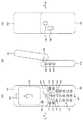
図1および図2は、本発明の実施形態に係る携帯電話10のオープン状態およびクローズ状態における外観の一例を図解した図である。
図1(A),(B),(C)は、オープン状態における携帯電話10の表側、側面、裏側の外観をそれぞれ示す。
図2(A),(B),(C)は、クローズ状態における携帯電話10の表側、側面、裏側の外観をそれぞれ示す。1 and 2 are diagrams illustrating an example of an appearance of the
1A, 1B, and 1C respectively show the front, side, and back side appearances of the
2A, 2 </ b> B, and 2 </ b> C respectively show the front, side, and back side appearances of the
図に示すように、携帯電話10は、2つの筐体(第1の筐体101、第2の筐体102)を有しており、これらの筐体が可動機構103を介して連結される。
第1の筐体101および第2の筐体102は、何れも角に丸みを帯びた長方形に近い板状の形を有しており、互いのサイズが近似している。これら2つの筐体は、上記した長方形の面上における片側の短辺の中央に近い部分において、長方形の面を互いに向けた状態で、可動機構103により連結される。可動機構103は、互いの長方形の面を貫く方向に伸びる回転軸を中心に、2つの筐体を相対的に回転させる。As shown in the figure, the
Each of the
オープン状態では、図1(A)および図1(C)に示すように、正面もしくは裏面から見ると2つの筐体の長辺が平行な状態になる。連結部に対して離れた側にあるそれぞれの筐体の短辺は、上述の回転軸を間に挟んで平行に向き合う配置となり、最も離れた状態になる。また、図1(B)に示すように、第2の筐体102は、横から見ると第1の筐体101に対し傾いた状態となる。 In the open state, as shown in FIGS. 1A and 1C, the long sides of the two casings are in parallel when viewed from the front or the back. The short sides of the respective housings on the side away from the connecting portion are arranged to face each other in parallel with the above-described rotation axis in between, and are in the most distant state. Further, as shown in FIG. 1B, the
一方、クローズ状態においても、図2(A)および図2(C)に示すように、2つの筐体の長辺は平行な状態になるが、連結部に対して離れた側にあるそれぞれの筐体の短辺は、上述の回転軸を間に挟まないで平行に向き合う配置となり、最も近づいた状態になる。また、図2(B)に示すように、第1の筐体101および第2の筐体102の長方形の面は横から見てほぼ平行になり、2つの筐体は互いに重ね合わせられた状態となる。 On the other hand, even in the closed state, as shown in FIGS. 2 (A) and 2 (C), the long sides of the two housings are in a parallel state. The short sides of the housing are arranged facing each other in parallel without interposing the above-mentioned rotation axis, and are in the closest state. In addition, as shown in FIG. 2B, the rectangular surfaces of the
第2の筐体102に接している側の第1の筐体101の面(以降、第1の筐体101の表面と表記する)上には、図1(A)に示すように、操作キー111〜119および121が配置される。これらの操作キーは、何れもオープン状態において使用されるキーであり、キー入力部154に含まれる。 On the surface of the
操作キー111および112は、処理モードに応じて種々の機能が割り当てられるキーである。
ここで、第1の筐体101の上側を連結部に近い側と定義すると(以降、この定義を用いて説明する)、操作キー111は、第1の筐体101の表面の左上隅に配置され、操作キー112は、この表面の右上隅に配置される。The
Here, if the upper side of the
操作キー113は、電子メールの作成・送信・受信等に関わる処理モードを呼び出す機能が割り当てられたキーであり、第1の筐体101の表面において、操作キー111の下に配置される。
操作キー114は、インターネットのWebページの閲覧に関わる処理モードを呼び出す機能が割り当てられたキーであり、第1の筐体101の表面において、操作キー112の下に配置される。The
The
操作キー115は、各種の処理モードにおいて処理対象の選択等に利用されるキーであり、上下左右の4方向のキーを含んだ楕円形の形状を有する。例えば、処理内容の一覧を画面に表示させて使用者に処理内容の選択を促す処理モード(以降、メニュー選択モードと表記する)において、選択の対象を上下左右に移動させるために用いられる。この操作キー115は、第1の筐体101の表面において、操作キー111および113と操作キー112および114との間に挟まれた位置に配置される。 The operation key 115 is a key used for selecting a processing target in various processing modes, and has an elliptical shape including keys in four directions, up, down, left, and right. For example, it is used to move a selection target up, down, left, and right in a processing mode (hereinafter, referred to as a menu selection mode) in which a list of processing contents is displayed on the screen to prompt the user to select processing contents. The operation key 115 is disposed on the surface of the
操作キー116は、各種の処理モードにおいて処理内容の決定等に利用されるキーである。例えば、上述したメニュー選択モードにおいて選択結果の決定を指示するために用いられる。また、カメラ撮影を行う処理モード(以降、カメラ・モードと表記する)においては、撮像の実行を指示するために用いられる。操作キー116は、操作キー115の楕円形の中心付近に配置される。 The
操作キー117は、電話機モードにおいて着信を受ける場合や発信を行う場合に利用されるキーであり、第1の筐体101の表面において、操作キー113の右下かつ操作キー115の左下の位置に配置される。
操作キー119は、各種の処理モードにおいて処理を終了する場合に利用されるキーである。例えば、電話機モードにおいて通話を終了する場合に用いられる。操作キー119は、第1の筐体101の表面において、操作キー114の左下かつ操作キー115の右下の位置に配置される。
操作キー118は、各種の処理モードにおいて文字やデータの消去を行う場合に利用されるキーであり、第1の筐体101の表面において、操作キー117および119の間に配置される。The operation key 117 is a key used when receiving an incoming call or making a call in the telephone mode. The operation key 117 is located on the surface of the
The
The operation key 118 is a key used for erasing characters and data in various processing modes, and is disposed between the
操作キー121は、操作キー117〜119の下側に、3列×4行の行列状に配列された、12個のキーからなる記号入力用のキー群である。これら12個のキーには、数字(「0」〜「9」)やアルファベット(「a」〜「z」,「A」〜「Z」)、記号(「*」、「#」、「/」等)を入力するためのキーが含まれる。 The
また、連結部を上側にして表面を見た場合における第1の筐体101の左側面(矢印Eの方向から見た第1の筐体101の側面)には、その連結部に近い側に、操作キー122〜124が配置される。 In addition, the left side surface of the first casing 101 (the side surface of the
操作キー122〜123は、主としてクローズ状態において使用されるキーであり、処理モードに応じて種々の機能が割り当てられる。また、操作キー122〜123は、キー入力部154に含まれる。
これらの3つの操作キーは、第1の筐体101の左側面において上寄りの位置に、操作キー122,123,124の順番で上から下へ一列に並んで配置される。The
These three operation keys are arranged in a line from the top to the bottom in the order of the
更に、連結部を上側にして操作キー110の面を見た場合における第1の筐体101の下側の側面には、そのほぼ中央に、マイク用の穴109が設けられる。 Further, a microphone hole 109 is provided at the approximate center of the lower side surface of the
また、第1の筐体101に接していない側の第2の筐体102の面上には、図1(A)および図2(A)に示すように、矩形の表示画面104が配置される。表示画面104は、例えばLCD(liquid crystal display)パネルや有機EL(electroluminescent)パネルなどの表示デバイスによって構成され、後述の表示部155に含まれる。 In addition, a
この表示画面104と同一の面上には、両端の短辺にそれぞれ近い位置に、表示画面104を挟んでスピーカ用の穴106および107が設けらる。穴107は連結部側の短辺の近くに配置され、穴106はその反対側の短辺の近くに配置される。
さらに、この面上には、連結部を下にして見た場合の左下隅に、カメラレンズ105が配置されている。カメラレンズ105は、後述の撮像部157に含まれる。On the same surface as the
Further, on this surface, a
また、図1(C)および図2(C)に示すように、第2の筐体102に接していない第1の筐体101の裏面には、カメラレンズ125およびフラッシュランプ126が配置されている。カメラレンズ125は、この裏面の連結部側の短辺に近い位置に配置されており、フラッシュランプ126は、連結部を上にして見た場合におけるカメラレンズ125の左下側の位置に配置されている。カメラレンズ125およびフラッシュランプ126は、撮像部157に含まれる。 As shown in FIGS. 1C and 2C, a
図3は、本発明の実施形態に係る携帯電話10の構成例を示すブロック図である。
図3に例示する携帯電話10は、通信処理部150と、記憶部152と、開閉判定部153と、キー入力部154と、表示部155と、音声入出力部156と、撮像部157と、制御部159とを有する。
記憶部152は、本発明の記憶手段の一実施形態である。
開閉判定部153は、本発明の作動状態判定手段の一実施形態である。
撮像部157は、本発明の撮像手段の一実施形態である。
制御部159は、本発明の制御手段の一実施形態である。FIG. 3 is a block diagram showing a configuration example of the
3 includes a
The
The open / close determining
The
The
通信処理部150は、基地局30との間の無線通信に関する処理を行う。例えば、制御部159から出力される送信データに所定の変調処理を施して無線信号に変換し、アンテナから送出する。また、アンテナにおいて受信された無線信号に所定の復調処理を施して受信データを再生し、制御部159に出力する。 The
記憶部152は、制御部159において実行されるプログラムや、制御部159の処理で用いられる定数データ、一時的に記憶が必要な変数データ、撮像画像データなどを記憶する。
例えば、表示画面上に撮像画像とともに表示される付加情報の画像の配置情報と開閉判定部153の判定結果とを関連づけたデータ・テーブルを記憶する。The
For example, a data table in which the arrangement information of the additional information image displayed together with the captured image on the display screen is associated with the determination result of the open /
開閉判定部153は、可動機構103による第1の筐体101および第2の筐体102の回転の状態が、上述したオープン状態またはクローズ状態の何れであるかを判定する。 The open / close determining
キー入力部154は、上述した操作キー110、120に対してキーを押下する等の入力操作が行なわれた場合、これに応じた信号を発生して制御部159に出力する。 When an input operation such as pressing a key is performed on the operation keys 110 and 120 described above, the
表示部155は、制御部159において生成される画像データに応じた画像を表示画面104に表示させる。 The
音声処理部156は、入力される音声をマイクにおいて電気的な音声信号に変換して増幅、アナログ−デジタル変換、符号化等の信号処理を施し、その処理結果の音声データを制御部159へ出力する。また、制御部159から入力される音声データに復号化、デジタル−アナログ変換、増幅等の信号処理を施して音声信号を生成し、これをスピーカにおいて音声に変換する。 The
撮像部157は、上述したカメラレンズ105や125において入射した像を撮像して静止画や動画の画像データを生成し、制御部159に出力する。また、制御部159の制御に従って、撮像時にフラッシュランプ126を点灯させる。 The
制御部159は、記憶部152に格納されるプログラムに基づいて処理を実行するコンピュータを有しており、携帯電話10の全体的な動作に関わる種々の処理を行う。
例えば、電話機の機能に関連する処理として、キー入力部154におけるキー入力操作に応じて通信処理部150の発呼、着信のシーケンスを制御する処理や、音声処理部156において入出力される音声データを通信処理部150において送受信させる処理を行う。
撮像機能に関連する処理としては、キー入力部154におけるキー入力操作に応じて撮像部157に静止画や動画の撮像処理を実行させる処理や、静止画の撮影時において適切なタイミングでフラッシュランプ126を点灯させる処理、撮像処理によって生成される画像データに圧縮符号化等の画像処理を施して記憶部152に格納する処理などを行う。The
For example, as processing related to the function of the telephone, processing for controlling a calling / incoming sequence of the
As a process related to the imaging function, the
また、制御部159は、これらの処理の流れを制御するための情報(以降、制御情報と表記する)の少なくとも一部と、その入力に用いる操作キーとの対応付けを、開閉判定部153の判定結果に応じて設定する。すなわち、制御部159は、少なくとも一部の制御情報を、オープン/クローズの状態に応じて異なる操作キーに対応付ける。 Further, the
例えばカメラ・モードにおいて、制御部159は、撮像の実行を指示するための撮像実行情報や、ズーム率を設定するためのズーム率設定情報、カメラ撮影に関する各種情報の設定を行うメニュー選択モードに遷移するためのモード遷移情報などを制御情報としてキー入力部154より入力する。
制御部159は、こうした制御情報と操作キーとの対応付けを、例えば表1に示すように設定する。すなわち、オープン状態において、撮像実行情報を操作キー116、ズーム率設定情報を操作キー111、モード遷移情報を操作キー112にそれぞれ対応付けし、クローズ状態においては、撮像実行情報を操作キー123、ズーム率設定情報を操作キー124、モード遷移情報を操作キー122にそれぞれ対応付ける。For example, in the camera mode, the
The

更に、制御部159は、カメラ・モードにおいて、撮像部157の撮像画像ととともに、種々の付加情報の画像を表示部155に表示させる。付加情報の画像には、例えば、後述する図5に示すように、制御情報と操作キーとの対応付けを表す画像(P4〜P6,P4A〜P6A)や、基地局より送信される信号の受信強度を表す画像(P2)、バッテリー残量を表す画像(P3)などが含まれる。 Further, in the camera mode, the
この場合、制御部159は、表示画面104上におけるこれらの付加情報の画像の配置(例えば位置や向き)を、開閉判定部153の判定結果に応じて変更する。すなわち、付加情報の画像の配置を、オープン/クローズの状態に応じて変更する。
この配置変更は、オープン状態およびクローズ状態のそれぞれで想定されている撮影時の筐体の持ち方に合わせて、表示画面104における付加情報の画像を使用者にとって見やすい配置にするものである。In this case, the
This arrangement change is made so that the image of the additional information on the
例えば、オープン状態の場合、第2の筐体102の連結部側の短辺から他方の短辺へ向かう方向(図1(A)の方向A)が表示画面の上方向となるように、筐体101および102の長手方向を縦に起こした状態で撮影が行なわれるものとする。また、オープン状態の場合は、上述した方向Eと反対の方向(図2(A)の方向B)が表示画面の上方向となるように、筐体101および102の長手方向を横に倒した状態で撮影が行なわれるものとする。
筐体の持ち方がこのように想定されているものとすると、制御部159は、オープン状態の場合に方向A、クローズ状態の場合に方向Bが表示画面104の上方向となるように、付加情報の画像の位置や向きを適切に設定する。For example, in the open state, the housing is arranged such that the direction from the short side on the coupling portion side of the
Assuming that the way of holding the housing is assumed in this way, the
また、こうした付加情報の画像配置の変更に際して、制御部159は、記憶部152に格納されているデータ・テーブルを参照する。このデータ・テーブルでは、開閉判定部153の判定結果(オープン状態またはクローズ状態)と、付加情報の画像の配置情報(表示画面104上での座標、回転角度など)とが関連づけられている。制御部159は、開閉判定部153の判定結果に対応する配置情報をこのデータ・テーブルから取得し、当該取得した配置情報に応じて、付加情報の画像の配置を変更する。 In addition, when changing the image arrangement of such additional information, the
ここで、上述した構成を有する携帯電話10の動作について、本発明に関連する撮像機能を中心に説明する。 Here, the operation of the
図4は、カメラ・モードの概略的な処理の流れの一例を図解したフローチャートである。 FIG. 4 is a flowchart illustrating an example of a schematic processing flow in the camera mode.
先ず、制御部159は、撮像部157における撮像処理を起動させ、撮像部157において順次に生成される撮像画像のデータを入力する(ステップST101)。 First, the
次いで、制御部159は、開閉判定部153の判定結果に基づいて、可動機構103がオープン状態またはクローズ状態の何れにあるかを判定する(ステップST102)。 Next, the
オープン状態であると判定した場合、制御部159は、縦撮影用の配置情報およびキーの対応付けを記憶部152のデータ・テーブルから取得する(ステップST103)。そして、撮像部157より入力されるデータに応じた撮像画像を表示部155に表示させるとともに、この縦撮影用の配置情報に基づいて配置が設定された各付加情報の画像を表示部155に表示させる(ステップST104)。
また、クローズ状態であると判定した場合、制御部159は、横撮影用の配置情報およびキーの対応付けを記憶部152のデータ・テーブルから取得する(ステップST105)。そして、撮像部157より入力されるデータに応じた撮像画像を表示部155に表示させるとともに、この横撮影用の配置情報に基づいて配置が設定された各付加情報の画像を表示部155に表示させる(ステップST106)。When it is determined that the camera is in the open state, the
If it is determined that the camera is in the closed state, the
上述のようにして表示部155に撮影用の画像が表示された状態でキー入力部154(オープン状態とクローズ状態とでキーの対応付けは変更される)より撮像実行情報が入力されると、制御部159は、撮像部157において生成された撮像画像データに圧縮符号化等の画像処理を施して、記憶部152に格納する(ステップST107)。 When imaging execution information is input from the key input unit 154 (the key association is changed between the open state and the closed state) in a state where the image for shooting is displayed on the
上述したステップST104、ST105における画像表示の例について、図5〜図7を参照して説明する。 An example of image display in steps ST104 and ST105 described above will be described with reference to FIGS.
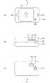
図5は、撮影時における表示画像の一例として、制御情報と操作キーとの対応付けを表す画像を含む場合の表示画像を図解した図である。図5(A)はオープン状態、図5(B)はクローズ状態における表示画像の例をそれぞれ示す。 FIG. 5 is a diagram illustrating a display image in a case where an image representing correspondence between control information and operation keys is included as an example of a display image at the time of shooting. FIG. 5A shows an example of a display image in an open state, and FIG. 5B shows an example of a display image in a closed state.
画像P1は、撮像部157において撮像された画像である。
画像P2は、基地局より送信される信号の受信強度を表す画像である。
画像P3は、バッテリー残量を表す画像である。The image P1 is an image captured by the
The image P2 is an image representing the reception intensity of the signal transmitted from the base station.
The image P3 is an image representing the remaining battery level.
図5(A)の画像P4〜P6および図5(B)の画像P4A〜P6Aは、制御情報と操作キーとの対応付けを表す画像である。
すなわち、画像P4は、ズーム率設定情報が操作キー111に対応付けられていることを表す。
画像P5は、撮像実行情報が操作キー116に対応付けられていることを表す。
画像P6は、モード遷移情報が操作キー112に対応付けられていることを表す。
画像P4Aは、ズーム率設定情報が操作キー124に対応付けられていることを表す。
画像P5Aは、撮像実行情報が操作キー123に対応付けられていることを表す。
画像P6Aは、モード遷移情報が操作キー122に対応付けられていることを表す。Images P4 to P6 in FIG. 5A and images P4A to P6A in FIG. 5B are images representing the association between control information and operation keys.
That is, the image P4 represents that the zoom ratio setting information is associated with the
The image P5 represents that the imaging execution information is associated with the
The image P6 represents that the mode transition information is associated with the
The image P4A represents that the zoom ratio setting information is associated with the
The image P5A represents that the imaging execution information is associated with the
The image P6A represents that the mode transition information is associated with the
図5に示すように、縦撮影時(オープン状態)および横撮影時(クローズ状態)の何れの場合も、各付加情報の画像は表示画面104の上方向(AまたはB)に対して正しい向きで配置される。
また、オープン状態の場合(図5(A))、表示画面104上において、受信強度を表す画像P2が左上隅に、バッテリー残量を表す画像P3が右上隅にそれぞれ配置される。制御情報と操作キーとの対応付けを示す画像については、ズーム率設定用キーを表す画像P4が左下隅に、メニュー選択モードへのモード遷移用キーを表す画像P6が右下隅に、撮像実行用キーを表す画像P5が画像P4およびP6の中間に、それぞれ配置される。したがって、図5(A)に示すように、表示画面104上における画像P4,P5,P6の並び順と、第1の筐体101上における操作キー111,116,112の並び順とが等しく、また、表示画面104上における画像P4,P5,P6の位置と第1の筐体101上における操作キー111,116,112の位置とがそれぞれ近くなることから、使用者は、画像P4,P5,P6と操作キー111,116,112とが対応付けられていることを直感的に把握できる。
クローズ状態の場合(図5(B))は、表示画面104上において、受信強度を表す画像P2が左上隅に、バッテリー残量を表す画像P3がその右隣にそれぞれ配置される。制御情報と操作キーとの対応付けを示す画像については、ズーム率設定用キーを表す画像P4Aが画像P3の右隣に、メニュー選択モードへのモード遷移用キーを表す画像P6Aが画面の右上隅に、撮像実行用キーを表す画像P5Aが画像P4AおよびP6Aの中間に、それぞれ配置される。したがって、クローズ状態の場合も、表示画面104上における画像P4A,P5A,P6Aの並び順と、第1の筐体101上における操作キー124,123,122の並び順とが等しく、また、表示画面104上における画像P4A,P5A,P6Aの位置と第1の筐体101上における操作キー124,123,122の位置とがそれぞれ近くなることから、使用者は、画像P4A,P5A,P6Aと操作キー124,123,122とが対応付けられていることを直感的に把握できる。
このように、使用者は、制御情報の画像が表示画面104上に配置される位置と向きを見るだけで、これに対応付けられている操作キーを直感的に把握できる。
また、オープン時には携帯電話を縦に構えた姿勢で操作しやすく、クローズ時には横に構えた姿勢で操作しやすくなるように操作キーと制御情報との対応付けを変えているにも関わらず、縦撮影時および横撮影時の表示レイアウトを近似させているため、撮影のスタイルを変更した場合でも表示画面の印象が変わらなくなり、使用者の違和感が少なくなる。As shown in FIG. 5, the image of each additional information is in the correct orientation with respect to the upward direction (A or B) of the
In the open state (FIG. 5A), on the
In the closed state (FIG. 5B), on the
In this way, the user can intuitively understand the operation keys associated with the control information image only by looking at the position and orientation at which the control information image is arranged on the
Also, although the correspondence between the operation keys and the control information has been changed so that the mobile phone can be easily operated in a vertical orientation when opened, and the mobile phone can be operated in a horizontal orientation when closed, Since the display layouts at the time of shooting and horizontal shooting are approximated, even when the shooting style is changed, the impression of the display screen does not change, and the user feels uncomfortable.
図6は、撮影時における表示画像の他の例として、撮像画像のズーム率を表す画像を含む場合の表示画像を図解した図である。図6(A)はオープン状態、図6(B)はクローズ状態における表示画像の例をそれぞれ示す。ただし、図5と図6の同一符号は同一の画像を示す。 FIG. 6 is a diagram illustrating a display image when an image representing the zoom rate of the captured image is included as another example of the display image at the time of shooting. 6A shows an example of a display image in an open state, and FIG. 6B shows an example of a display image in a closed state. 5 and 6 indicate the same image.
図6の例では、図5の例における画像P4〜P6およびP4A〜P6Aの代わりに、撮像画像のズーム率を表す画像P7が表示されている。
画像P7は、画面の横方向に伸びる棒型の外形を有し、この棒の中には、ズーム率に応じて左右に移動する正方形に近い矩形のマークを有する。In the example of FIG. 6, an image P7 representing the zoom rate of the captured image is displayed instead of the images P4 to P6 and P4A to P6A in the example of FIG.
The image P7 has a bar-shaped outer shape extending in the horizontal direction of the screen, and the bar has a rectangular mark close to a square that moves to the left and right according to the zoom rate.
画像P7は、図6(A)および図6(B)に示すように、オープン状態およびクローズ状態の何れの場合も、表示画面104の上方向(AまたはB)に対して同様な位置に同様な向きで配置されている。すなわち、撮像画像P1の下側に、棒を横に倒す向きで配置されている。
したがって、この場合も、縦撮影時および横撮影時の表示レイアウトが近似するため、使用者の違和感が少なくなる。As shown in FIG. 6 (A) and FIG. 6 (B), the image P7 is similarly located at the same position with respect to the upper direction (A or B) of the
Accordingly, in this case as well, the display layouts at the time of vertical shooting and horizontal shooting are approximated, so that the user feels uncomfortable.
なお、制御部159は、開閉判定部153の判定結果に応じて、ズーム率を表す画像の長手方向の長さを変更しても良い。例えば図7に示すように、横方向に画面が広がる横撮影時においては、縦撮影時の画像P7より長手方向の長さを伸ばした画像P7Aを表示させても良い。これにより、ズーム率の細かい制御が容易になるとともに、ズーム率の細かい識別が可能になる。 Note that the
あるいは、制御部159は、開閉判定部153の判定結果によらず、ズーム率を表す画像の表示画面104上における配置を一定に保っても良い。例えば図8に示すように、横撮影時と縦撮影時とにおいて画像P7の配置を同じとし、他の付加情報の画像の配置を開閉判定部153の判定結果に応じて変更しても良い。これにより、画像P7を横に倒して表示させていたスペースに空きが生じるため、ここに例えば上述した画像P4A〜P6Aを表示させるなどして、表示画面104の有効な利用が可能になる。 Alternatively, the
以上説明したように、本実施形態によれば、表示部155の表示画面104上において撮像画像とともに表示される付加情報の画像の配置が開閉判定部153の判定結果に応じて変更される。
そのため、オープン状態の場合とクローズ状態の場合とで撮影しやすい筐体の持ち方が異なるとともに、その持ち方の違いによって使用者に対する表示画面104の向きが変わってしまう場合でも、それぞれの持ち方における表示画面の向きに合わせて付加情報の画像の配置を適切に変更することが可能になり、付加情報の視認性を高めることができる。As described above, according to the present embodiment, the arrangement of the additional information image displayed together with the captured image on the
For this reason, the manner of holding the case that is easy to shoot differs between the open state and the closed state, and even if the orientation of the
また、開閉判定部153の判定結果と付加情報の画像の配置情報とを関連づけたデータ・テーブルが予め記憶部152に格納されており、制御部159において、開閉判定部153の判定結果に対応する上記の配置情報がこのデータ・テーブルから取得され、当該取得された配置情報に応じて付加情報の画像の配置が変更される。
したがって、オープン状態とクローズ状態のそれぞれについて付加情報の画像データを個別に用意する必要がなくなるため、こうした画像データの記憶に必要な領域が少なくなり、メモリを節約することができる。In addition, a data table in which the determination result of the open /
Therefore, it is not necessary to separately prepare image data of additional information for each of the open state and the closed state, so that an area necessary for storing such image data is reduced, and the memory can be saved.
なお、本発明は上述した実施形態に限定されず、種々の改変が可能である。 The present invention is not limited to the above-described embodiment, and various modifications can be made.
例えば、上述した図6〜図8では撮像画像のズーム率を表す画像P7、P7Aを付加情報の画像の一例として示しているが、同様な棒型の画像を動画撮影の経過時間を表す画像として表示しても良い。
例えば図6において、棒の左端に矩形のマークが位置する状態を経過時間ゼロとして、撮影開始とともに、マークを左から右へ移動させる。棒の左端からのマークの移動距離は、動画撮影の経過時間に比例させる。このような制御部159の処理により、画像P7と同様な画像を動画撮影の経過時間を表す画像として表示部155に表示させても良い。
この場合、棒の左端から右端までマークが到達するまでの経過時間を、携帯電話10が一度の通信で伝送できる最大のデータ量に対応した動画像の撮影時間としても良い。For example, in FIGS. 6 to 8 described above, the images P7 and P7A representing the zoom rate of the captured image are shown as an example of the additional information image, but a similar bar-shaped image is used as an image representing the elapsed time of moving image shooting. You may display.
For example, in FIG. 6, the state in which the rectangular mark is located at the left end of the bar is set to zero elapsed time, and the mark is moved from left to right with the start of imaging. The moving distance of the mark from the left end of the bar is proportional to the elapsed time of moving image shooting. By such processing of the
In this case, the elapsed time until the mark reaches from the left end to the right end of the stick may be a moving image shooting time corresponding to the maximum amount of data that the
また、制御部159は、表示画面104上に表示させる撮像画像の大きさやアスペクト比を、開閉判定部153の判定結果に応じて変更しても良い。これにより、表示画面104上の画像のレイアウトを、それぞれの操作スタイルに合わせて、より自由に変更することができる。 The
また、制御部159は、開閉判定部153の判定結果に応じて、撮像画像データの再生画像に所定角度の回転が生じるように、撮像画像データ中における各画素のデータ配列を変換しても良い。 Further, the
仮に、縦撮影(オープン状態)および横撮影(クローズ状態)で同一の被写体を撮影し、それぞれの撮像画像データをそのまま再生したとすると、一方の画像中の被写体は他方の画像中の被写体に対して90°横に倒れた状態で表示される。
したがって、例えば縦撮影の撮像画像データを基準として、横撮影の撮像画像データの再生画像に90°の回転が生じるようにその撮像画像データ中における各画素のデータ配列を変換すれば、縦撮影および横撮影の両方の再生画像の向きを揃えることができる。Assuming that the same subject is shot in vertical shooting (open state) and horizontal shooting (closed state), and each captured image data is reproduced as it is, the subject in one image is compared to the subject in the other image. Is displayed in a state of being tilted 90 ° sideways.
Therefore, for example, if the data array of each pixel in the captured image data is converted so that a reproduction image of the horizontally captured image data is rotated by 90 ° with reference to the vertically captured image data, the vertical shooting and It is possible to align the orientations of both playback images for landscape shooting.
上述した実施形態において、第1の筐体101の側面に操作キー122〜124が配置されているが、この例に限らず、例えば第2の筐体102の側面にこれらのキーを配置させても良いし、第2の筐体102の表面にこれらのキーを配置させても良い。 In the embodiment described above, the
また、上述した実施形態においては、情報入力手段としてキー型の入力手段を用いる例が示されているが、この例に限らず、例えばホイールやボールの回転の検出によって情報を入力するものや、静電気、光等を利用した非接触型の情報入力手段など、他の種々の情報入力手段を本発明に適用しても良い。 In the above-described embodiment, an example using a key-type input unit as the information input unit is shown. However, the present invention is not limited to this example. For example, information input by detecting rotation of a wheel or a ball, Various other information input means such as non-contact information input means using static electricity or light may be applied to the present invention.
上述した実施形態では、制御部159の処理がコンピュータによってプログラムに基づいて処理される例を示したが、これらの処理の少なくとも一部をハードウェアによって実行させることも可能である。
また、逆に、制御部159以外の他のユニットにおける少なくとも一部の処理を、制御部159のコンピュータにおいて実行させても良い。In the above-described embodiment, an example in which the processing of the
Conversely, at least a part of processing in units other than the
10…携帯電話、102…第1の筐体、102…第2の筐体、103…可動機構、104…表示画面、105,125…カメラレンズ、106,107…スピーカ用の穴、109…マイク用の穴、111〜119,121〜124…操作キー、126…フラッシュランプ、150…通信処理部、152…記憶部、153…開閉判定部、154…キー入力部、155…表示部、156…音声処理部、157…撮像部、159…制御部
DESCRIPTION OF
Claims (8)
Translated fromJapanese撮像画像を表示する表示手段を備え、可動機構を介して上記第1の筐体に連結された第2の筐体と、
上記可動機構の作動状態を判定する作動状態判定手段と、
上記作動状態判定手段の判定結果に応じて、上記表示手段の表示画面上において上記撮像画像とともに表示される付加情報の画像の配置を変更する制御手段と、
を有することを特徴とする撮像装置。A first housing;
A second housing that includes display means for displaying a captured image and is coupled to the first housing via a movable mechanism;
An operating state determining means for determining an operating state of the movable mechanism;
Control means for changing the arrangement of the image of the additional information displayed together with the captured image on the display screen of the display means according to the determination result of the operating state determination means;
An imaging device comprising:
上記制御手段は、上記作動状態判定手段の判定結果に対応する上記配置情報を上記記憶手段から取得し、当該取得した配置情報に応じて、上記付加情報の画像の配置を変更する、
請求項1に記載の撮像装置。Storage means for storing the arrangement information of the image of the additional information on the display screen in association with the determination result of the operating state determination means;
The control means acquires the arrangement information corresponding to the determination result of the operating state determination means from the storage means, and changes the arrangement of the image of the additional information according to the acquired arrangement information.
The imaging device according to claim 1.
上記制御手段は、撮像機能に関連する処理の流れを制御するための情報と、当該情報の入力に用いる上記情報入力手段との対応付けを、上記作動状態判定手段において判定された作動状態に応じて設定し、当該対応付けが設定された少なくとも一部の情報入力手段を表す画像の上記表示画面上における位置および向きを、当該判定された作動状態に応じて変更する、
請求項1または2に記載の撮像装置。A plurality of information input means disposed in one or both of the first casing and the second casing;
The control means associates the information for controlling the flow of processing related to the imaging function with the information input means used for inputting the information according to the operation state determined by the operation state determination means. Changing the position and orientation on the display screen of the image representing at least a part of the information input means for which the association is set according to the determined operating state.
The imaging device according to claim 1 or 2.
上記制御手段は、上記ズーム率もしくは上記経過時間を表す画像の上記表示画面上における位置および向きを、上記作動状態判定手段の判定結果に応じて変更する、
請求項1乃至3の何れか一に記載の撮像装置。The additional information includes the zoom rate of the captured image or the elapsed time of moving image shooting,
The control means changes the position and orientation of the image representing the zoom rate or the elapsed time on the display screen according to the determination result of the operating state determination means.
The imaging device according to any one of claims 1 to 3.
上記制御手段は、上記ズーム率もしくは上記経過時間を表す画像の長手方向の長さを、上記作動状態判定手段の判定結果に応じて変更する、
請求項4に記載の撮像装置。The image representing the zoom ratio or the elapsed time is formed in a substantially rectangular shape,
The control means changes the length in the longitudinal direction of the image representing the zoom ratio or the elapsed time according to the determination result of the operating state determination means.
The imaging device according to claim 4.
上記制御手段は、上記ズーム率もしくは上記経過時間を表す画像の上記表示画面上における位置および向きを、上記作動状態判定手段の判定結果によらず一定に保つと共に、上記ズーム率もしくは上記経過時間を表す画像を除く上記付加情報の画像の配置を上記作動状態判定手段の判定結果に応じて変更する、
請求項1乃至3の何れか一に記載の撮像装置。The additional information includes the zoom rate of the captured image or the elapsed time of moving image shooting,
The control means maintains the position and orientation of the image representing the zoom ratio or the elapsed time on the display screen constant regardless of the determination result of the operating state determination means, and the zoom ratio or the elapsed time. Changing the arrangement of the image of the additional information excluding the image to be represented according to the determination result of the operating state determination means,
The imaging device according to any one of claims 1 to 3.
請求項1乃至6の何れか一に記載の撮像装置。The control means changes the size or aspect ratio of the captured image to be displayed on the display screen according to the determination result of the operating state determination means.
The imaging device according to any one of claims 1 to 6.
撮像手段と、
上記2つの筐体の一方に配置され、上記撮像手段の撮像画像を表示する表示手段と、
上記可動機構の作動状態が、上記表示手段を備える筐体によって他方の筐体の所定の領域を覆う第1の作動状態、または、当該所定の領域を露出させる第2の作動状態の何れであるかを判定する作動状態判定手段と、
上記作動状態判定手段の判定結果に応じて、上記表示手段の表示画面上において上記撮像画像とともに表示される付加情報の画像の配置を変更する制御手段と、
を有することを特徴とする撮像装置。
An imaging apparatus having two housings and a movable mechanism for rotating the two housings around a common rotation axis,
Imaging means;
A display unit disposed on one of the two casings and displaying a captured image of the imaging unit;
The operating state of the movable mechanism is either a first operating state in which a predetermined region of the other housing is covered by the housing having the display means, or a second operating state in which the predetermined region is exposed. Operating state determining means for determining whether or not
Control means for changing the arrangement of the image of the additional information displayed together with the captured image on the display screen of the display means according to the determination result of the operating state determination means;
An imaging device comprising:
Priority Applications (3)
| Application Number | Priority Date | Filing Date | Title |
|---|---|---|---|
| JP2003356927AJP4288134B2 (en) | 2003-10-16 | 2003-10-16 | Imaging device |
| US10/965,288US20050085280A1 (en) | 2003-10-16 | 2004-10-14 | Imaging apparatus |
| CNB2004100881424ACN100571336C (en) | 2003-10-16 | 2004-10-14 | imaging device |
Applications Claiming Priority (1)
| Application Number | Priority Date | Filing Date | Title |
|---|---|---|---|
| JP2003356927AJP4288134B2 (en) | 2003-10-16 | 2003-10-16 | Imaging device |
Publications (2)
| Publication Number | Publication Date |
|---|---|
| JP2005123908Atrue JP2005123908A (en) | 2005-05-12 |
| JP4288134B2 JP4288134B2 (en) | 2009-07-01 |
Family
ID=34509812
Family Applications (1)
| Application Number | Title | Priority Date | Filing Date |
|---|---|---|---|
| JP2003356927AExpired - Fee RelatedJP4288134B2 (en) | 2003-10-16 | 2003-10-16 | Imaging device |
Country Status (3)
| Country | Link |
|---|---|
| US (1) | US20050085280A1 (en) |
| JP (1) | JP4288134B2 (en) |
| CN (1) | CN100571336C (en) |
Cited By (7)
| Publication number | Priority date | Publication date | Assignee | Title |
|---|---|---|---|---|
| JP2009055598A (en)* | 2007-08-28 | 2009-03-12 | Victor Co Of Japan Ltd | Video camera |
| JP2011170764A (en)* | 2010-02-22 | 2011-09-01 | Canon Inc | Display control device and method for controlling the same, program, and storage medium |
| JP2012142971A (en)* | 2008-02-26 | 2012-07-26 | Nec Casio Mobile Communications Ltd | Imaging apparatus, and program |
| WO2013161583A1 (en) | 2012-04-25 | 2013-10-31 | Sony Corporation | Display control device and device control method |
| JP2015228252A (en)* | 2011-10-07 | 2015-12-17 | パナソニック インテレクチュアル プロパティ コーポレーション オブアメリカPanasonic Intellectual Property Corporation of America | Photographing device |
| KR101739378B1 (en) | 2010-12-23 | 2017-05-24 | 삼성전자주식회사 | Digital image photographing apparatus and method for controlling the same |
| CN109040349A (en)* | 2018-06-08 | 2018-12-18 | Oppo广东移动通信有限公司 | electronic device, drive control method and related product |
Families Citing this family (9)
| Publication number | Priority date | Publication date | Assignee | Title |
|---|---|---|---|---|
| US20060209197A1 (en)* | 2005-03-15 | 2006-09-21 | Nokia Corporation | Camera devices |
| USD530698S1 (en)* | 2005-04-27 | 2006-10-24 | Samsung Electronics Co., Ltd. | Mobile phone |
| USD546313S1 (en)* | 2006-03-09 | 2007-07-10 | Lg Electronics, Inc. | Mobile phone |
| USD534516S1 (en)* | 2006-03-09 | 2007-01-02 | Lg Electronics Inc. | Mobile phone |
| TWI339978B (en)* | 2006-03-29 | 2011-04-01 | High Tech Comp Corp | Handheld device havind a digital alblum for preserving history images and the application thereof |
| US20080100735A1 (en)* | 2006-10-31 | 2008-05-01 | Samsung Electro-Mechanics Co., Ltd. | Image sensor, camera module having the same, and mobile terminal having the same |
| JP4364273B2 (en) | 2007-12-28 | 2009-11-11 | パナソニック株式会社 | Portable terminal device, display control method, and display control program |
| JP4710930B2 (en)* | 2008-06-20 | 2011-06-29 | コニカミノルタビジネステクノロジーズ株式会社 | Data processing apparatus, data processing method, and data processing program |
| US8908350B2 (en)* | 2008-06-25 | 2014-12-09 | Core Wireless Licensing S.A.R.L. | Capacitor |
Family Cites Families (14)
| Publication number | Priority date | Publication date | Assignee | Title |
|---|---|---|---|---|
| US5737293A (en)* | 1994-09-21 | 1998-04-07 | Matsushita Electric Industrial Co. Ltd. | Disc loading apparatus for loading optical discs in a cartridge or without |
| US6009336A (en)* | 1996-07-10 | 1999-12-28 | Motorola, Inc. | Hand-held radiotelephone having a detachable display |
| TW589620B (en)* | 2001-09-26 | 2004-06-01 | Teac Corp | Disc device |
| JP2003174495A (en)* | 2001-09-28 | 2003-06-20 | Nec Corp | Folding portable information terminal |
| US6888532B2 (en)* | 2001-11-30 | 2005-05-03 | Palmone, Inc. | Automatic orientation-based user interface for an ambiguous handheld device |
| US6952601B2 (en)* | 2002-02-21 | 2005-10-04 | Mobicom Corporation | Display for a portable terminal |
| FI113130B (en)* | 2002-04-17 | 2004-02-27 | Nokia Corp | Portable, foldable electronic device equipped with telephone and camera functions |
| JP4080395B2 (en)* | 2002-08-02 | 2008-04-23 | シャープ株式会社 | Portable information processing device |
| JP3949048B2 (en)* | 2002-11-18 | 2007-07-25 | 京セラ株式会社 | Stackable mobile terminal device |
| KR101007412B1 (en)* | 2003-01-21 | 2011-01-12 | 파나소닉 주식회사 | Mobile devices |
| KR100504144B1 (en)* | 2003-01-30 | 2005-07-27 | 삼성전자주식회사 | Method for sensing a position of folder in a rotation touchable phone having a camera |
| US7583317B2 (en)* | 2003-03-04 | 2009-09-01 | Sanyo Electric Co., Ltd. | Foldable electronic image pickup apparatus |
| US20040223004A1 (en)* | 2003-05-05 | 2004-11-11 | Lincke Scott D. | System and method for implementing a landscape user experience in a hand-held computing device |
| US7542781B2 (en)* | 2003-06-30 | 2009-06-02 | Casio Computer Co., Ltd. | Handheld electronic apparatus |
- 2003
- 2003-10-16JPJP2003356927Apatent/JP4288134B2/ennot_activeExpired - Fee Related
- 2004
- 2004-10-14CNCNB2004100881424Apatent/CN100571336C/ennot_activeExpired - Fee Related
- 2004-10-14USUS10/965,288patent/US20050085280A1/ennot_activeAbandoned
Cited By (20)
| Publication number | Priority date | Publication date | Assignee | Title |
|---|---|---|---|---|
| JP2009055598A (en)* | 2007-08-28 | 2009-03-12 | Victor Co Of Japan Ltd | Video camera |
| JP2012142971A (en)* | 2008-02-26 | 2012-07-26 | Nec Casio Mobile Communications Ltd | Imaging apparatus, and program |
| JP2011170764A (en)* | 2010-02-22 | 2011-09-01 | Canon Inc | Display control device and method for controlling the same, program, and storage medium |
| KR101739378B1 (en) | 2010-12-23 | 2017-05-24 | 삼성전자주식회사 | Digital image photographing apparatus and method for controlling the same |
| US10306144B2 (en) | 2011-10-07 | 2019-05-28 | Panasonic Corporation | Image pickup device and image pickup method |
| US9800785B2 (en) | 2011-10-07 | 2017-10-24 | Panasonic Corporation | Image pickup device and image pickup method |
| US9547434B2 (en) | 2011-10-07 | 2017-01-17 | Panasonic Corporation | Image pickup device and image pickup method |
| US9607554B2 (en) | 2011-10-07 | 2017-03-28 | Panasonic Corporation | Image pickup device and image pickup method |
| US9648228B2 (en) | 2011-10-07 | 2017-05-09 | Panasonic Corporation | Image pickup device and image pickup method |
| JP2015228252A (en)* | 2011-10-07 | 2015-12-17 | パナソニック インテレクチュアル プロパティ コーポレーション オブアメリカPanasonic Intellectual Property Corporation of America | Photographing device |
| US11678051B2 (en) | 2011-10-07 | 2023-06-13 | Panasonic Holdings Corporation | Image pickup device and image pickup method |
| US9443476B2 (en) | 2011-10-07 | 2016-09-13 | Panasonic Intellectual Property Corporation Of America | Image pickup device and image pickup method |
| US11272104B2 (en) | 2011-10-07 | 2022-03-08 | Panasonic Corporation | Image pickup device and image pickup method |
| US10531000B2 (en) | 2011-10-07 | 2020-01-07 | Panasonic Corporation | Image pickup device and image pickup method |
| WO2013161583A1 (en) | 2012-04-25 | 2013-10-31 | Sony Corporation | Display control device and device control method |
| KR20180093126A (en) | 2012-04-25 | 2018-08-20 | 소니 주식회사 | Information processing apparatus, method and program thereof |
| EP3343901A1 (en) | 2012-04-25 | 2018-07-04 | Sony Corporation | Display control device and device control method |
| KR20170088440A (en) | 2012-04-25 | 2017-08-01 | 소니 주식회사 | Information processing apparatus, method and program thereof |
| CN109040349A (en)* | 2018-06-08 | 2018-12-18 | Oppo广东移动通信有限公司 | electronic device, drive control method and related product |
| CN109040349B (en)* | 2018-06-08 | 2020-05-26 | Oppo广东移动通信有限公司 | Electronic device, drive control method, and related products |
Also Published As
| Publication number | Publication date |
|---|---|
| CN1610385A (en) | 2005-04-27 |
| CN100571336C (en) | 2009-12-16 |
| US20050085280A1 (en) | 2005-04-21 |
| JP4288134B2 (en) | 2009-07-01 |
Similar Documents
| Publication | Publication Date | Title |
|---|---|---|
| JP4288134B2 (en) | Imaging device | |
| JP3516328B2 (en) | Information communication terminal equipment | |
| KR100627018B1 (en) | Computer-readable recording medium recording image display apparatus, image display method and program for controlling on-screen display | |
| US20090075692A1 (en) | Mobile terminal | |
| JP2006311224A (en) | Folding mobile phone | |
| JP2016536895A (en) | Method and terminal for acquiring panoramic image | |
| JP2006303651A (en) | Electronic equipment | |
| JP2002094629A (en) | Information communication terminal equipment | |
| CN104935810A (en) | Photographing guiding method and device | |
| JP2004179923A (en) | Portable telephone set, and method for setting original animation of continuously-shot images, which is used for the same | |
| KR20090045117A (en) | Portable and Imaging Devices | |
| JP4359717B2 (en) | Portable terminal device and program | |
| JP4403931B2 (en) | Electronic device, display method and display program | |
| JP4352465B2 (en) | Mobile device | |
| JP4294433B2 (en) | Mobile terminal device | |
| KR101474415B1 (en) | Portable terminal | |
| JP2011151515A (en) | Electronic device with imaging function, portable telephone set with camera function, display method of image data, and display program of image data | |
| KR100735705B1 (en) | Mobile terminal having video communication function and video communication method using same | |
| KR101371022B1 (en) | Portable terminal | |
| KR200352488Y1 (en) | Personal communication device with camera having a function of remote control | |
| JP4757468B2 (en) | Portable information processing apparatus, new arrival information presentation method, and new arrival information presentation program | |
| JP4905871B2 (en) | Information display device | |
| KR101427271B1 (en) | Mobile terminal | |
| JP4917124B2 (en) | Portable information display device | |
| JP2005148326A (en) | Data receiving apparatus, display control method, and display control program |
Legal Events
| Date | Code | Title | Description |
|---|---|---|---|
| A621 | Written request for application examination | Free format text:JAPANESE INTERMEDIATE CODE: A621 Effective date:20060912 | |
| A977 | Report on retrieval | Free format text:JAPANESE INTERMEDIATE CODE: A971007 Effective date:20090223 | |
| TRDD | Decision of grant or rejection written | ||
| A01 | Written decision to grant a patent or to grant a registration (utility model) | Free format text:JAPANESE INTERMEDIATE CODE: A01 Effective date:20090303 | |
| A01 | Written decision to grant a patent or to grant a registration (utility model) | Free format text:JAPANESE INTERMEDIATE CODE: A01 | |
| A61 | First payment of annual fees (during grant procedure) | Free format text:JAPANESE INTERMEDIATE CODE: A61 Effective date:20090330 | |
| FPAY | Renewal fee payment (event date is renewal date of database) | Free format text:PAYMENT UNTIL: 20120403 Year of fee payment:3 | |
| R150 | Certificate of patent or registration of utility model | Ref document number:4288134 Country of ref document:JP Free format text:JAPANESE INTERMEDIATE CODE: R150 Free format text:JAPANESE INTERMEDIATE CODE: R150 | |
| FPAY | Renewal fee payment (event date is renewal date of database) | Free format text:PAYMENT UNTIL: 20120403 Year of fee payment:3 | |
| FPAY | Renewal fee payment (event date is renewal date of database) | Free format text:PAYMENT UNTIL: 20130403 Year of fee payment:4 | |
| FPAY | Renewal fee payment (event date is renewal date of database) | Free format text:PAYMENT UNTIL: 20130403 Year of fee payment:4 | |
| FPAY | Renewal fee payment (event date is renewal date of database) | Free format text:PAYMENT UNTIL: 20140403 Year of fee payment:5 | |
| LAPS | Cancellation because of no payment of annual fees |