JP2005123049A - Light guide plate - Google Patents
Light guide plateDownload PDFInfo
- Publication number
- JP2005123049A JP2005123049AJP2003357494AJP2003357494AJP2005123049AJP 2005123049 AJP2005123049 AJP 2005123049AJP 2003357494 AJP2003357494 AJP 2003357494AJP 2003357494 AJP2003357494 AJP 2003357494AJP 2005123049 AJP2005123049 AJP 2005123049A
- Authority
- JP
- Japan
- Prior art keywords
- groove
- light
- guide plate
- light guide
- grooves
- Prior art date
- Legal status (The legal status is an assumption and is not a legal conclusion. Google has not performed a legal analysis and makes no representation as to the accuracy of the status listed.)
- Pending
Links
- 238000000034methodMethods0.000abstractdescription4
- 238000009826distributionMethods0.000description5
- NIXOWILDQLNWCW-UHFFFAOYSA-Nacrylic acid groupChemical groupC(C=C)(=O)ONIXOWILDQLNWCW-UHFFFAOYSA-N0.000description4
- 239000004925Acrylic resinSubstances0.000description2
- 229920000178Acrylic resinPolymers0.000description2
- 230000007423decreaseEffects0.000description2
- 230000000694effectsEffects0.000description2
- 238000004519manufacturing processMethods0.000description2
- 238000009792diffusion processMethods0.000description1
- 239000004973liquid crystal related substanceSubstances0.000description1
- 229920003229poly(methyl methacrylate)Polymers0.000description1
- 239000004926polymethyl methacrylateSubstances0.000description1
- 230000001902propagating effectEffects0.000description1
- 239000011347resinSubstances0.000description1
- 229920005989resinPolymers0.000description1
- 238000007788rougheningMethods0.000description1
Images


Landscapes
- Light Guides In General And Applications Therefor (AREA)
- Liquid Crystal (AREA)
- Non-Portable Lighting Devices Or Systems Thereof (AREA)
- Planar Illumination Modules (AREA)
Abstract
Description
Translated fromJapanese本発明は、液晶表示装置等におけるバックライトや面光源等に利用される導光板に関し、特に、透明な導光板の出光面と対向する対向面に複数のV字状凹溝を設け、端面から導光板に導いた光をこれら凹溝で反射させ、出光面から外部に出射させる導光板の構造に関するものである。 The present invention relates to a light guide plate used for a backlight, a surface light source or the like in a liquid crystal display device or the like, and in particular, a plurality of V-shaped grooves are provided on an opposing surface facing a light exit surface of a transparent light guide plate, The present invention relates to a structure of a light guide plate that reflects light guided to the light guide plate by these concave grooves and emits the light from the light exit surface to the outside.
この種の導光板は、光が出射する主面としての出光面と、出光面に対向する対向面とを備え、対向面には端面から入射する光に対して略直交する方向に延びる断面略V字状の凹溝が形成されており、端面から入射された光のうち臨界角を超えない光はそのまま出光面から出射し、臨界角を超える光は出光面と対向面との間で反射を繰り返し、前記凹溝部分で反射方向が変えられて出光面から出射する構造とされている。 This type of light guide plate includes a light exit surface as a main surface from which light is emitted and a facing surface facing the light exit surface, and the facing surface has a cross-section extending in a direction substantially orthogonal to light incident from the end surface. A V-shaped groove is formed, and light that does not exceed the critical angle out of the light incident from the end face is emitted as it is from the light exit surface, and light that exceeds the critical angle is reflected between the light exit surface and the opposing surface. The reflection direction is changed at the concave groove portion, and the light exits from the light exit surface.
一方、光源から遠ざかるに従って導光板内を伝播する光強度は減衰するため、出光面内の輝度を均一にするためには、光源からの距離が遠ざかるに従って出光面側へ反射する割合を高める必要がある。 On the other hand, the intensity of light propagating through the light guide plate decreases as the distance from the light source decreases. Therefore, in order to make the luminance within the light exit surface uniform, it is necessary to increase the rate of reflection toward the light exit surface as the distance from the light source increases. is there.
そこで、光が入射する端面から遠ざかるに従って対向面に形成された凹溝の溝間隔がより密になるように形成され、遠ざかるに従ってより多くの光を出光面に向けて反射させる構造とした導光板や(例えば、特許文献1および特許文献2参照。)、光が入射する端面から遠ざかるに従って対向面に形成された凹溝の溝深さがより深くなるように形成され、遠ざかるに従ってより多くの光を出光面に向けて反射させる構造とした導光板が提案されている(例えば、特許文献3参照。)。 Therefore, the light guide plate has a structure in which the groove interval of the concave grooves formed on the opposing surface becomes closer as the distance from the end face where the light enters, and the light is reflected toward the light exit surface as the distance increases. (For example, refer to
一方、導光板には透明なアクリル樹脂(PMMA)が多く用いられ、厚みは通常2〜6mmである。そして、このような導光板の出光面で輝度ムラ(いわゆる縞状のムラ)が生じないようにするため、隣り合う凹溝の溝間隔は0.6mm以下、好ましくは0.3mm以下にする必要がある。また、凹溝の溝深さは0.01〜0.1mm程度が好ましい。 On the other hand, a transparent acrylic resin (PMMA) is often used for the light guide plate, and the thickness is usually 2 to 6 mm. In order to prevent luminance unevenness (so-called striped unevenness) from occurring on the light exit surface of such a light guide plate, the groove interval between adjacent grooves should be 0.6 mm or less, preferably 0.3 mm or less. There is. The groove depth of the concave groove is preferably about 0.01 to 0.1 mm.
しかしながら、上記のように光が入射する端面から遠ざかるに従って凹溝の溝間隔を徐々に密にしていく方法によれば、光源に最も遠い部分では高密度で多数の凹溝を形成する必要があり、また、上記のように光が入射する端面から遠ざかるに従って凹溝の溝深さを徐々に深くしていく方法によれば、僅かずつの違いの溝深さを高精度で加工する必要がある。 However, according to the method in which the groove interval of the grooves is gradually increased as the distance from the end face where the light is incident as described above, it is necessary to form a large number of grooves at a high density in the portion farthest from the light source. In addition, according to the method of gradually increasing the groove depth of the concave groove as it moves away from the end face where the light is incident as described above, it is necessary to process the groove depth of a slight difference with high accuracy. .
このような溝間隔や溝深さには輝度ムラ発生の観点からそれぞれ好ましい上限があるため、大きく反射割合を変えるためには微細な溝作製が必要となり、導光板のコスト高を招くという欠点があった。 Since such groove intervals and groove depths each have a preferable upper limit from the viewpoint of occurrence of luminance unevenness, in order to greatly change the reflection ratio, it is necessary to produce fine grooves, leading to high cost of the light guide plate. there were.
これに対し、本願出願人は溝間隔および溝深さ(溝幅)をそれぞれ変化させることにより反射割合を大きく変化させることに気付いた。 In contrast, the applicant of the present application has noticed that the reflection ratio is greatly changed by changing the groove interval and groove depth (groove width).
そこで、本発明の解決しようとする課題は、高度の加工精度が要求されず、凹溝の加工本数の削減を図った安価な導光板を提供することにある。 Therefore, the problem to be solved by the present invention is to provide an inexpensive light guide plate that does not require a high degree of processing accuracy and that reduces the number of grooves processed.
前記課題を解決するための技術的手段は、透明な導光板の主面を光が出射する出光面とし、この出光面に対向する対向面上に、光源からの光が入射する入射端面に略平行な複数のV字状凹溝を形成してなる導光板において、前記凹溝は、前記光源から遠ざかるほど、互いの溝間隔が密になるように形成されると共に凹溝の溝幅が広くなるように形成された点にある。 The technical means for solving the above-described problem is that the main surface of the transparent light guide plate is a light exit surface from which light is emitted, and the light incident surface from which the light from the light source is incident on the opposite surface facing the light exit surface. In the light guide plate formed with a plurality of parallel V-shaped concave grooves, the concave grooves are formed such that the distance between the concave grooves increases as the distance from the light source increases, and the width of the concave grooves increases. It is in the point formed to become.
また、前記光源からの距離が一定の区間で、前記凹溝の前記溝間隔もしくは前記溝幅のいずれか一方のみが変化する領域を有してなる構造としてもよい。 Moreover, it is good also as a structure which has an area | region where only either the said groove | channel space | interval or the said groove | channel width of the said concave groove changes in the area where the distance from the said light source is constant.
本発明の導光板によれば、入射端面に略平行な複数のV字状凹溝は、光源から遠ざかるほど、互いの溝間隔が密になるように形成されると共に凹溝の溝幅が広くなるように形成された構造とされており、溝間隔と溝幅の両方を変化させる構造としているため、光源に近い部分ではそれほど細くなくてもよく、光源から遠い部分では太幅の凹溝を用いて凹溝の加工本数を減らしても十分に略均一な輝度分布が得られ、高度の加工精度が要求されず、凹溝の加工本数も削減でき、製造コスト削減が図れ、安価な導光板を提供できる。 According to the light guide plate of the present invention, the plurality of V-shaped grooves substantially parallel to the incident end face are formed such that the distance between the grooves becomes closer as the distance from the light source increases, and the groove width of the grooves increases. Since it is structured to change both the groove interval and the groove width, it does not have to be so thin in the part close to the light source, and a thick groove in the part far from the light source. Even if the number of grooves is reduced, a sufficiently uniform brightness distribution can be obtained, high processing accuracy is not required, the number of grooves can be reduced, manufacturing costs can be reduced, and an inexpensive light guide plate Can provide.
また、光源からの距離が一定の区間で、凹溝の溝間隔もしくは溝幅のいずれか一方のみが変化する領域を有してなる構造によれば、即ち、一定の区間で凹溝の溝間隔のみが変化する領域を有する構造とした場合、この一定の区間では凹溝の溝幅が一定であるため、同じ溝幅の加工工具が利用でき、反射割合の調整も溝間隔のみの調整で容易に行え、加工コスト低減が図れ、さらには、入射端面から遠い反射割合を高くする部分では輝度ムラが生じない程度の溝間隔に合わせて太い凹溝を形成することにより加工コストも低減できる。 Further, according to the structure having a region in which only one of the groove interval or groove width of the groove changes in a section where the distance from the light source is constant, that is, the groove interval of the groove in the certain section. In the case of a structure having only a variable region, since the groove width of the concave groove is constant in this fixed section, a processing tool having the same groove width can be used, and the reflection ratio can be easily adjusted by adjusting only the groove interval. In addition, the processing cost can be reduced, and further, the processing cost can be reduced by forming the thick concave grooves in accordance with the groove interval that does not cause uneven brightness in the portion where the reflection ratio far from the incident end face is increased.
一方、一定の区間で凹溝の溝幅のみが変化する領域を有する構造とした場合、この一定の区間では凹溝の溝間隔が一定であるため、入射端面から近く反射割合を低くすべき部分では、溝間隔を輝度ムラが生じない範囲で粗くすることにより、微細な凹溝を形成する必要がなくなり、入射端面から遠い反射割合を高くする部分では輝度ムラが生じない程度の溝間隔に合わせて太い凹溝を形成することにより加工コストも低減できる。 On the other hand, when a structure having an area where only the groove width of the groove changes in a certain section, the groove spacing of the groove is constant in this certain section, so the portion where the reflection ratio should be low near the incident end face Then, by roughening the groove interval in a range where uneven brightness does not occur, it is not necessary to form fine grooves, and the groove interval is adjusted so that uneven brightness does not occur in the portion where the reflection ratio is high from the incident end face. The processing cost can be reduced by forming thick and thick grooves.
以下、本発明の第1の実施形態を図面に基づいて説明すると、図1および図2に示される如く、導光板1は、透明な樹脂板、例えばアクリル樹脂で形成されたアクリル板からなり、平面視矩形の板状に形成されている。 Hereinafter, a first embodiment of the present invention will be described with reference to the drawings. As shown in FIGS. 1 and 2, the
そして、導光板1の上面は光が出射する出光面1aとされ、この出光面1aに対向する下面の対向面1b上に、複数のV字状凹溝1cが形成されている。また、導光板1の一側端面は、光源としてのLED(発光ダイオード)2からの光が入射する入射端面1dとされ、この入射端面1dに対して前記各凹溝1cが略平行に形成されている。 The upper surface of the
さらに、各凹溝1cは、入射端面1dから他方の他側端面1eに向けて、即ち、各LED2から遠ざかるほど、互いに隣接する溝間隔Pが漸次密になるように形成されると共に、各LED2から遠ざかるほど、各凹溝1cの溝幅S(もしくは溝深さH)が漸次広くなるように形成されている。 Furthermore, each
本実施形態は以上のように構成されており、凹溝1cにおける溝間隔Pと溝幅Sの両方を変化させる構造としているため、LED2に近い部分では凹溝1cをそれほど細くなくてもよく、LED2から遠い部分では太幅の凹溝1cを用いて凹溝1cの加工本数を減らしても十分に略均一な輝度分布が得られ、ここに、高度の加工精度が要求されず、凹溝1cの加工本数も削減でき、製造コスト削減が図れ、安価な導光板1を提供できる。 Since the present embodiment is configured as described above and has a structure in which both the groove interval P and the groove width S in the
例えば、本実施形態では、幅150mm、長さ50mm、厚み2mmの透明のアクリル板の対向面1bに、頂角が90°の二等辺三角形の凹溝1cが形成された構造とされている。従って、溝幅Sの1/2が溝深さHとなっている。そして、長辺側の端面となる入射端面1d側に、その長手方向に沿って適宜数のLED2が並列配置され、この入射端面1dから光を入射する構造とされている。 For example, in the present embodiment, an isosceles triangular
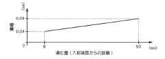
また、入射端面1dから8mmの位置に、最も近い凹溝1cを溝幅Sが0.04mm、溝間隔Pが0.3mmで形成し、他側端面1e方向に向けて溝幅Sを徐々に広げながら溝間隔Pを漸次密に形成し、その他端では凹溝1cを溝幅Sが0.09mm、溝間隔Pが0.15mmで形成した構造とされている。 Further, the nearest
そして、図2に示すように、収容ケース4上に反射フィルム5を配置し、その反射フィルム5上に対向面1bを下面として導光板1を配置している。また、導光板1の出光面1a上には拡散フィルム6を介して輝度上昇フィルムとしてのプリズムレンズシート7(住友3M製BEFII)を配置し、さらに、導光板1の入射端面1d側に各LED2を配置した構造の導光板モジュールを構成している。この場合の導光板モジュールにおいては、面内の輝度分布は輝度ムラが±20%であり、略均一なバックライトとして提供できる。 Then, as shown in FIG. 2, the
なお、V字状凹溝1cにおいては、LED2から遠いところにおいては、凹溝1c部分と対向面1bの凹溝1c間の平坦部分のそれぞれの幅、いわゆる投影面積比が略等しいときに最も多くの光を出射することができるが、導光板1の板厚や凹溝1cのV字状の角度、光源(LED2)の指向性等によりこのような最適な投影面積比は変化し、50%〜60%の範囲内で設定することが好ましい。 In the V-
従って、LED2に近い部分では縞にならないように溝間隔Pを0.3mmとし、最も遠い部分では投影面積比を50%〜60%とすればよい。例えば、最も遠い部分で凹溝1cの溝幅Sを0.15mmとすれば、溝間隔Pを0.3mmとすればよく、凹溝1cの溝幅Sを0.3mmとすれば、溝間隔Pを0.6mmとすればよい。 Therefore, the groove interval P may be set to 0.3 mm so as not to be striped in the portion close to the
図5ないし図7は第2の実施形態を示しており、前記第1の実施形態と同様構成部分は同一符号を付し、その説明を省略する。 5 to 7 show a second embodiment, and the same components as those in the first embodiment are denoted by the same reference numerals, and the description thereof is omitted.
即ち、本実施形態においては、対向面1bに対する凹溝1cの形成に際して、LED2、即ち入射端面1dからの距離が一定の区間では、凹溝1cの溝間隔Pのみが変化する一方変化領域Aと、凹溝1cの溝間隔Pと溝幅Sの両方を変化させる両方変化領域Bとを有した構造とされている。 That is, in the present embodiment, when the
本実施形態は以上のように構成されており、第1の実施形態と同様の効果を奏すると共に、入射端面1dからの距離が一定の区間では凹溝1cの溝幅Sが一定であるため、一方変化領域Aにおける凹溝1cの形成に際しては、同じ加工工具を利用でき、反射割合の調整も溝間隔Pのみの調整で容易に行え、加工コスト低減が図れ、さらには、入射端面1dから遠い反射割合を高くする部分では輝度ムラが生じない程度の溝間隔Pに合わせて太い凹溝1cを形成することにより加工コストも低減できる利点がある。 The present embodiment is configured as described above, and has the same effect as the first embodiment, and the groove width S of the
例えば、本実施形態では、第1の実施形態と同様、幅150mm、長さ50mm、厚み3mmの透明のアクリル板の対向面1bに、頂角が90°の二等辺三角形の凹溝1cが形成された構造とされている。そして、入射端面1dから5mmの位置に、最も近い凹溝1cを溝幅Sが0.05mm、溝間隔Pが0.4mmで形成し、他側端面1e方向に向けて溝幅S一定で溝間隔Pを漸次密に形成し、入射端面1dから30mmの位置で溝間隔Pを0.25mmに形成した。 For example, in this embodiment, as in the first embodiment, an isosceles triangular
また、入射端面1dからの距離が30mmから50mm(他端)まで、溝間隔Pを0.25mmから0.2mmまで漸次狭めながら、溝幅Sを0.05mmから0.1mmまで徐々に広げて形成した構造とされている。 Further, the groove width S is gradually increased from 0.05 mm to 0.1 mm while the distance P from the
そして、この場合も第1の実施形態と同様構成の導光板モジュールに仕上げた場合、面内の輝度分布は輝度ムラが±20%であり、この場合においても略均一なバックライトとして提供できる。 Also in this case, when the light guide plate module having the same configuration as that of the first embodiment is finished, the in-plane luminance distribution has a luminance unevenness of ± 20%, and even in this case, it can be provided as a substantially uniform backlight.
図8および図9は第3の実施形態を示しており、前記第1の実施形態と同様構成部分は同一符号を付し、その説明を省略する。 8 and 9 show a third embodiment, and the same components as those in the first embodiment are denoted by the same reference numerals, and the description thereof is omitted.
即ち、本実施形態においては、対向面1bに対する凹溝1cの形成に際して、LED2、即ち入射端面1dからの距離が一定の区間では、凹溝1cの溝幅Sのみが変化する一方変化領域Aと、凹溝1cの溝間隔Pと溝幅Sの両方を変化させる両方変化領域Bとを有した構造とされている。 That is, in the present embodiment, when the
本実施形態は以上のように構成されており、第1の実施形態と同様の効果を奏すると共に、入射端面1dからの距離が一定の区間では凹溝1cの溝間隔Pが一定であるため、入射端面1dから近く反射割合を低くすべき部分では、溝間隔Pを輝度ムラが生じない範囲で粗くすることにより、微細な凹溝1cを多数形成する必要がなくなり、入射端面1dから遠い反射割合を高くする部分では輝度ムラが生じない程度の溝間隔Pに合わせて太い凹溝1cを形成することにより加工コストも低減できる利点がある。 This embodiment is configured as described above, and has the same effect as that of the first embodiment, and the groove interval P of the
例えば、本実施形態では、第1の実施形態と同様、幅150mm、長さ55mm、厚み2mmの透明のアクリル板の対向面1bに、頂角が90°の二等辺三角形の凹溝1cが形成された構造とされている。そして、入射端面1dから5mmの位置に、最も近い凹溝1cを溝幅Sが0.02mm、溝間隔Pが0.3mmで形成し、他側端面1e方向に向けて44mmの位置まで溝間隔P一定で溝幅Sを徐々に広げながら形成し、入射端面1dから44mmの位置で溝幅Sを0.07mmに形成した。 For example, in this embodiment, an isosceles triangular
また、入射端面1dからの距離が44mmから55mm(他端)まで、溝間隔Pを0.3mmから0.2mmまで漸次狭めながら、溝幅Sを0.07mmから0.1mmまで徐々に広げて形成した構造とされている。 Further, the groove width S is gradually increased from 0.07 mm to 0.1 mm while the distance P from the
そしてこの場合、導光板1における面内の輝度分布は前記導光板モジュールのプリズムレンズシート7が無くても輝度ムラが±30%であり、この場合においても略均一なバックライトとして提供できる。 In this case, the in-plane luminance distribution in the
なお、上記各実施形態において、V字状の凹溝1cの頂角が90°の二等辺三角形に形成された構造を示しているが、頂角の角度は実施形態に何ら限定されず、必要に応じて適宜変更すればよい。 In addition, in each said embodiment, although the structure formed in the isosceles triangle whose apex angle of the V-shaped
また、各実施形態における凹溝1cの溝間隔Pや溝幅Sの関係も実施形態に何ら限定されない。 Further, the relationship between the groove interval P and the groove width S of the
さらに、各実施形態において、導光板1における入射端面1dが一方のみに設けられた構造を示しているが、他方にも光源からの光が入射する入射端面1dを備えた構造等、導光板1の複数位置に入射端面1dを設ける構造としてもよい。 Furthermore, in each embodiment, the
1 導光板
1a 出光面
1b 対向面
1c 凹溝
1d 入射端面
1 LED
DESCRIPTION OF
Claims (2)
Translated fromJapanese前記凹溝は、前記光源から遠ざかるほど、互いの溝間隔が密になるように形成されると共に凹溝の溝幅が広くなるように形成されたことを特徴とする導光板。The main surface of the transparent light guide plate is a light exit surface from which light is emitted, and a plurality of V-shaped grooves that are substantially parallel to the incident end surface on which light from the light source is incident are formed on the opposing surface facing the light exit surface. In the light guide plate
The light guide plate according to claim 1, wherein the groove is formed so that a distance between the grooves becomes closer as the distance from the light source increases, and a groove width of the groove is increased.
前記光源からの距離が一定の区間で、前記凹溝の前記溝間隔もしくは前記溝幅のいずれか一方のみが変化する領域を有してなることを特徴とする導光板。
The light guide plate according to claim 1,
A light guide plate having a region in which only one of the groove interval and the groove width of the concave groove changes in a section having a constant distance from the light source.
Priority Applications (1)
| Application Number | Priority Date | Filing Date | Title |
|---|---|---|---|
| JP2003357494AJP2005123049A (en) | 2003-10-17 | 2003-10-17 | Light guide plate |
Applications Claiming Priority (1)
| Application Number | Priority Date | Filing Date | Title |
|---|---|---|---|
| JP2003357494AJP2005123049A (en) | 2003-10-17 | 2003-10-17 | Light guide plate |
Publications (1)
| Publication Number | Publication Date |
|---|---|
| JP2005123049Atrue JP2005123049A (en) | 2005-05-12 |
Family
ID=34614365
Family Applications (1)
| Application Number | Title | Priority Date | Filing Date |
|---|---|---|---|
| JP2003357494APendingJP2005123049A (en) | 2003-10-17 | 2003-10-17 | Light guide plate |
Country Status (1)
| Country | Link |
|---|---|
| JP (1) | JP2005123049A (en) |
Cited By (5)
| Publication number | Priority date | Publication date | Assignee | Title |
|---|---|---|---|---|
| WO2008019621A1 (en)* | 2006-08-14 | 2008-02-21 | Shaohua Ren | A surface light source for a table lamp, a reading lamp or lighting fixtures |
| TWI411821B (en)* | 2009-01-22 | 2013-10-11 | Au Optronics Corp | Light guide plate and backlight module having v-cut structure |
| WO2013168392A1 (en)* | 2012-05-10 | 2013-11-14 | パナソニック株式会社 | Light guide |
| CN105090839A (en)* | 2014-05-23 | 2015-11-25 | 惠州Tcl照明电器有限公司 | Ceiling lamp |
| US20160018584A1 (en)* | 2013-01-30 | 2016-01-21 | Cree, Inc. | Optical Waveguide and Luminaire Incorporating Same |
- 2003
- 2003-10-17JPJP2003357494Apatent/JP2005123049A/enactivePending
Cited By (10)
| Publication number | Priority date | Publication date | Assignee | Title |
|---|---|---|---|---|
| WO2008019621A1 (en)* | 2006-08-14 | 2008-02-21 | Shaohua Ren | A surface light source for a table lamp, a reading lamp or lighting fixtures |
| TWI411821B (en)* | 2009-01-22 | 2013-10-11 | Au Optronics Corp | Light guide plate and backlight module having v-cut structure |
| WO2013168392A1 (en)* | 2012-05-10 | 2013-11-14 | パナソニック株式会社 | Light guide |
| CN104272011A (en)* | 2012-05-10 | 2015-01-07 | 松下知识产权经营株式会社 | light guide plate |
| US9229151B2 (en) | 2012-05-10 | 2016-01-05 | Panasonic Intellectual Property Management Co., Ltd. | Light guide |
| JPWO2013168392A1 (en)* | 2012-05-10 | 2016-01-07 | パナソニックIpマネジメント株式会社 | Light guide plate |
| US20160018584A1 (en)* | 2013-01-30 | 2016-01-21 | Cree, Inc. | Optical Waveguide and Luminaire Incorporating Same |
| US9823408B2 (en)* | 2013-01-30 | 2017-11-21 | Cree, Inc. | Optical waveguide and luminaire incorporating same |
| CN105090839A (en)* | 2014-05-23 | 2015-11-25 | 惠州Tcl照明电器有限公司 | Ceiling lamp |
| CN105090839B (en)* | 2014-05-23 | 2018-05-18 | 惠州Tcl照明电器有限公司 | Ceiling lamp |
Similar Documents
| Publication | Publication Date | Title |
|---|---|---|
| JP6237998B2 (en) | Light guide plate and surface light source device | |
| US9223074B2 (en) | Light guide plate and area light source device | |
| JP4307477B2 (en) | Light guide plate and backlight unit | |
| CN101630037B (en) | Backlight module and light guide plate thereof | |
| US20120201045A1 (en) | Light guide plate, surface light source device and transmissive display apparatus | |
| US9261637B2 (en) | Surface light source device and its light guide plate | |
| JP4433467B2 (en) | Surface light source device | |
| JP2002098838A (en) | Rod-like light guide body, linear illumination device which uses the same and surface illumination device which uses the linear illumination device | |
| KR20130004178A (en) | Symmetric serrated edge light guide film having elliptical base segments | |
| KR20060045376A (en) | LGP for LCD backlight | |
| JP2005353406A (en) | Light guide plate | |
| US20130063976A1 (en) | Asymmetric serrated edge light guide film having circular base segments | |
| US20130063975A1 (en) | Asymmetric serrated edge light guide film having elliptical base segments | |
| US7295261B2 (en) | Light guide plate with W-shaped structures and backlight module using the same | |
| JP2006261064A (en) | Light guide plate and backlight device | |
| JP2017188250A (en) | Planar lighting device | |
| JP2009251122A (en) | Light guide plate and backlight device | |
| TW201426125A (en) | Light guide plate and backlight module | |
| JP2004192937A (en) | Light guide plate | |
| JP2005123049A (en) | Light guide plate | |
| JP2006227347A (en) | Backlight unit for liquid crystal display device and liquid crystal display device | |
| JP5984363B2 (en) | Light guide plate, surface light source device, and transmissive image display device | |
| TWM619355U (en) | Light guide plate and light source module | |
| US8480283B2 (en) | Asymmetric serrated edge light guide film having elliptical base segments | |
| JP2007123086A (en) | Surface light source apparatus |