JP2005121947A - Object lens insertion fixture, microscope and microscope system - Google Patents
Object lens insertion fixture, microscope and microscope systemDownload PDFInfo
- Publication number
- JP2005121947A JP2005121947AJP2003357577AJP2003357577AJP2005121947AJP 2005121947 AJP2005121947 AJP 2005121947AJP 2003357577 AJP2003357577 AJP 2003357577AJP 2003357577 AJP2003357577 AJP 2003357577AJP 2005121947 AJP2005121947 AJP 2005121947A
- Authority
- JP
- Japan
- Prior art keywords
- objective lens
- insertion tool
- lens unit
- observation
- microscope
- Prior art date
- Legal status (The legal status is an assumption and is not a legal conclusion. Google has not performed a legal analysis and makes no representation as to the accuracy of the status listed.)
- Pending
Links
- 238000003780insertionMethods0.000titleclaimsabstractdescription226
- 230000037431insertionEffects0.000titleclaimsabstractdescription226
- 210000003491skinAnatomy0.000claimsdescription11
- 210000002615epidermisAnatomy0.000claimsdescription10
- 238000007789sealingMethods0.000claimsdescription4
- 230000000149penetrating effectEffects0.000claimsdescription3
- 230000003287optical effectEffects0.000description22
- 239000013307optical fiberSubstances0.000description20
- 238000003825pressingMethods0.000description13
- 238000005452bendingMethods0.000description9
- 239000007788liquidSubstances0.000description9
- 238000011282treatmentMethods0.000description9
- 238000010586diagramMethods0.000description4
- 230000003247decreasing effectEffects0.000description2
- 239000003814drugSubstances0.000description2
- 239000007850fluorescent dyeSubstances0.000description2
- 238000003384imaging methodMethods0.000description2
- 210000001519tissueAnatomy0.000description2
- 230000000007visual effectEffects0.000description2
- 206010061218InflammationDiseases0.000description1
- XKRFYHLGVUSROY-UHFFFAOYSA-NargonSubstances[Ar]XKRFYHLGVUSROY-UHFFFAOYSA-N0.000description1
- 229910052786argonInorganic materials0.000description1
- 230000009286beneficial effectEffects0.000description1
- 239000003795chemical substances by applicationSubstances0.000description1
- 238000001514detection methodMethods0.000description1
- 238000007599dischargingMethods0.000description1
- 230000000694effectsEffects0.000description1
- 239000000835fiberSubstances0.000description1
- CPBQJMYROZQQJC-UHFFFAOYSA-Nhelium neonChemical compound[He].[Ne]CPBQJMYROZQQJC-UHFFFAOYSA-N0.000description1
- 238000005286illuminationMethods0.000description1
- 230000004054inflammatory processEffects0.000description1
- 230000001678irradiating effectEffects0.000description1
- 230000007774longtermEffects0.000description1
- 238000000034methodMethods0.000description1
- 238000011328necessary treatmentMethods0.000description1
- 210000000056organAnatomy0.000description1
- 238000012856packingMethods0.000description1
- 230000002093peripheral effectEffects0.000description1
- 239000000126substanceSubstances0.000description1
- XLYOFNOQVPJJNP-UHFFFAOYSA-NwaterSubstancesOXLYOFNOQVPJJNP-UHFFFAOYSA-N0.000description1
Images


Classifications
- A—HUMAN NECESSITIES
- A61—MEDICAL OR VETERINARY SCIENCE; HYGIENE
- A61B—DIAGNOSIS; SURGERY; IDENTIFICATION
- A61B1/00—Instruments for performing medical examinations of the interior of cavities or tubes of the body by visual or photographical inspection, e.g. endoscopes; Illuminating arrangements therefor
- A61B1/313—Instruments for performing medical examinations of the interior of cavities or tubes of the body by visual or photographical inspection, e.g. endoscopes; Illuminating arrangements therefor for introducing through surgical openings, e.g. laparoscopes
- A—HUMAN NECESSITIES
- A61—MEDICAL OR VETERINARY SCIENCE; HYGIENE
- A61B—DIAGNOSIS; SURGERY; IDENTIFICATION
- A61B1/00—Instruments for performing medical examinations of the interior of cavities or tubes of the body by visual or photographical inspection, e.g. endoscopes; Illuminating arrangements therefor
- A61B1/012—Instruments for performing medical examinations of the interior of cavities or tubes of the body by visual or photographical inspection, e.g. endoscopes; Illuminating arrangements therefor characterised by internal passages or accessories therefor
- A61B1/015—Control of fluid supply or evacuation
- A—HUMAN NECESSITIES
- A61—MEDICAL OR VETERINARY SCIENCE; HYGIENE
- A61B—DIAGNOSIS; SURGERY; IDENTIFICATION
- A61B90/00—Instruments, implements or accessories specially adapted for surgery or diagnosis and not covered by any of the groups A61B1/00 - A61B50/00, e.g. for luxation treatment or for protecting wound edges
- A61B90/20—Surgical microscopes characterised by non-optical aspects
- A—HUMAN NECESSITIES
- A61—MEDICAL OR VETERINARY SCIENCE; HYGIENE
- A61B—DIAGNOSIS; SURGERY; IDENTIFICATION
- A61B2503/00—Evaluating a particular growth phase or type of persons or animals
- A61B2503/40—Animals
Landscapes
- Health & Medical Sciences (AREA)
- Life Sciences & Earth Sciences (AREA)
- Surgery (AREA)
- Molecular Biology (AREA)
- General Health & Medical Sciences (AREA)
- Veterinary Medicine (AREA)
- Engineering & Computer Science (AREA)
- Biomedical Technology (AREA)
- Heart & Thoracic Surgery (AREA)
- Medical Informatics (AREA)
- Nuclear Medicine, Radiotherapy & Molecular Imaging (AREA)
- Animal Behavior & Ethology (AREA)
- Pathology (AREA)
- Public Health (AREA)
- Physics & Mathematics (AREA)
- Biophysics (AREA)
- Optics & Photonics (AREA)
- Radiology & Medical Imaging (AREA)
- Oral & Maxillofacial Surgery (AREA)
- Microscoopes, Condenser (AREA)
- Endoscopes (AREA)
Abstract
Description
Translated fromJapanese本発明は、光学機器において対物レンズユニットを挿入する対物レンズ挿入具と、このような対物レンズ挿入具を備える顕微鏡と、該顕微鏡を含む顕微鏡システムに関する。 The present invention relates to an objective lens insertion tool for inserting an objective lens unit in an optical apparatus, a microscope including such an objective lens insertion tool, and a microscope system including the microscope.
生きた細胞や組織などの試料の表面や、断層像を観察する手段としては、共焦点レーザ走査型顕微鏡が知られている。共焦点レーザ走査型顕微鏡は、レーザ光源と光検出器とが対物レンズに対して光学的に共益な位置関係になるように配置されている。さらに、レーザ光源と対物レンズとの間に走査光学系が設けられ、レーザビームを試料に対して2次元又は3次元に走査させながら、試料の像を取得する。ここで、従来の共焦点レーザ走査型顕微鏡には、観察したい部位に近接させる対物レンズと、走査光学系とを光ファイバの束で光学的に結合したものがある(例えば、特許文献1参照)。
しかしながら、この種の共焦点レーザ走査型顕微鏡で同一の試料を複数回に渡って観察する場合には、観察の度に試料と対物レンズとの位置合わせをしなければならない。このような位置合わせは、試料が小動物の内部組織などである場合には、特に困難である。また、対物レンズの倍率を代えた場合にも位置合わせを行わなければならなかった。
さらに、細胞などを複数回に渡って観察する場合には、観察対象の内部に異物が入らないようにする必要がある。
この発明は、このような課題を鑑みてなされたものであり、観察の度に行われていた対物レンズの位置合わせを不要にすることを目的とする。また、観察対象の内部に異物が入らないようにすることを目的とする。そして、そのような対物レンズユニットが取り付けられた顕微鏡や、このような顕微鏡を含む顕微鏡システムを提供することを目的とする。However, when the same sample is observed a plurality of times with this type of confocal laser scanning microscope, the sample and the objective lens must be aligned for each observation. Such alignment is particularly difficult when the sample is a small animal internal tissue or the like. In addition, alignment has to be performed when the magnification of the objective lens is changed.
Furthermore, when observing cells or the like multiple times, it is necessary to prevent foreign matter from entering the inside of the observation target.
This invention is made in view of such a subject, and it aims at making the position alignment of the objective lens performed every time of observation unnecessary. It is another object of the present invention to prevent foreign matter from entering the observation target. And it aims at providing the microscope in which such an objective lens unit was attached, and the microscope system containing such a microscope.
上記の課題を解決する本発明の請求項1に係る発明は、観察対象の表皮に当接する基部から前記観察対象内に挿入される挿入部を延出させ、前記観察対象の内部を観察するために用いられる対物レンズを位置決めして挿入可能な挿入孔を設けた本体と、前記挿入部に嵌合可能で、前記基部との間で前記表皮を挟み込む固定部材と、を有することを特徴とする対物レンズ挿入具とした。
この対物レンズ挿入具は、基部と固定部材とで表皮を挟み込むことで観察対象に位置決めして固定することができる。この状態で挿入孔に対物レンズユニットを挿入すると、対物レンズが、対物レンズ挿入具を介して観察対象に位置決めして固定される。In order to observe the inside of the observation object, the invention according to
This objective lens insertion tool can be positioned and fixed to the observation object by sandwiching the epidermis between the base and the fixing member. When the objective lens unit is inserted into the insertion hole in this state, the objective lens is positioned and fixed to the observation target via the objective lens insertion tool.
請求項2に係る発明は、請求項1に記載の対物レンズ挿入具において、前記挿入孔を複数設けたことを特徴とする。
この対物レンズ挿入具によれば、観察しようとする部位が近接して複数ある場合に、そのそれぞれに対物レンズユニットを挿入して観察することが可能になる。According to a second aspect of the present invention, in the objective lens insertion tool according to the first aspect, a plurality of the insertion holes are provided.
According to this objective lens insertion tool, when there are a plurality of parts to be observed close to each other, the objective lens unit can be inserted into each of the parts to be observed.
請求項3に係る発明は、請求項1に記載の対物レンズ挿入具において、前記挿入孔を密閉可能な蓋を備えることを特徴とする。
この対物レンズ挿入具によれば、対物レンズユニットを取り外した後に挿入孔を蓋で密閉することが可能になる。The invention according to claim 3 is the objective lens insertion tool according to
According to this objective lens insertion tool, it is possible to seal the insertion hole with the lid after removing the objective lens unit.
請求項4に係る発明は、請求項3に記載の対物レンズ挿入具において、前記基部から延びる弾性部材の先端に前記蓋を備えることを特徴とする。
この対物レンズ挿入具は、蓋が基部と一体に設けられているので、蓋の取り外しが容易になる。According to a fourth aspect of the present invention, in the objective lens insertion tool according to the third aspect, the lid is provided at the tip of an elastic member extending from the base.
In this objective lens insertion tool, since the lid is provided integrally with the base, it is easy to remove the lid.
請求項5に係る発明は、請求項3に記載の対物レンズ挿入具において、前記蓋は、前記挿入孔を塞ぐ弾性部材に、少なくとも1つの切り込みを設けて形成されていることを特徴とする。
この対物レンズ挿入具は、切り込みにより形成される複数の弾性片から蓋が構成される。この弾性片は、対物レンズユニットを取り外すと貫通孔を密閉し、対物レンズユニットを挿入孔に挿入すると開口を形成するように変形する。According to a fifth aspect of the present invention, in the objective lens insertion tool according to the third aspect, the lid is formed by providing at least one cut in an elastic member that closes the insertion hole.
In this objective lens insertion tool, a lid is composed of a plurality of elastic pieces formed by cutting. The elastic piece is deformed so as to seal the through hole when the objective lens unit is removed and to form an opening when the objective lens unit is inserted into the insertion hole.
請求項6に係る発明は、請求項1に記載の対物レンズ挿入具において、前記本体は、前記基部に対して移動可能な微動部を有し、前記挿入孔は、前記微動部に設けられていることを特徴とする。
この対物レンズ挿入具によれば、対物レンズユニットを挿入した微動部を基部に対して移動させることで、対物レンズの位置を移動させることができる。According to a sixth aspect of the present invention, in the objective lens insertion tool according to the first aspect, the main body has a fine movement portion movable with respect to the base portion, and the insertion hole is provided in the fine movement portion. It is characterized by being.
According to this objective lens insertion tool, the position of the objective lens can be moved by moving the fine movement portion into which the objective lens unit is inserted with respect to the base portion.
請求項7に係る発明は、請求項1に記載の対物レンズ挿入具において、前記本体に、前記基部から前記挿入部の先端まで貫通する貫通孔を設けたことを特徴とする。
この対物レンズ挿入具は、対物レンズを挿入する孔とは別の孔を有し、この孔には、処置具を挿入したり、ライトガイドを挿入したりできる。また、この孔を利用して空気や薬剤を観察対象内に供給することができる。The invention according to
The objective lens insertion tool has a hole different from the hole for inserting the objective lens, and a treatment tool or a light guide can be inserted into the hole. Moreover, air and a chemical | medical agent can be supplied in an observation object using this hole.
請求項8に係る発明は、請求項7に記載の対物レンズ挿入具において、前記基部から延びる弾性部材を設け、前記弾性部材の先端に、前記貫通孔を密閉可能な蓋を設けたことを特徴とする。
この対物レンズ挿入具は、貫通孔を使用しないときには蓋で密閉することができる。The invention according to claim 8 is the objective lens insertion tool according to
This objective lens insertion tool can be sealed with a lid when the through hole is not used.
請求項9に係る発明は、請求項1から請求項8のいずれか一項に記載の対物レンズ挿入具と、前記対物レンズ挿入具に挿入される対物レンズユニットと、光源からの光を前記観察対象に照射して得られた光を前記対物レンズを通して検出する光検出器とを含んで構成されることを特徴とする顕微鏡とした。
この顕微鏡で観察を行う際には、対物レンズ挿入具を観察したい部位に固定し、その後に対物レンズユニットを対物レンズ挿入具の挿入孔に挿入する。対物レンズ挿入具により対物レンズの位置が、観察対象に固定される。The invention according to a ninth aspect is the objective lens insertion tool according to any one of the first to eighth aspects, the objective lens unit inserted into the objective lens insertion tool, and the observation of light from a light source. The microscope includes a photodetector that detects light obtained by irradiating the object through the objective lens.
When observing with this microscope, the objective lens insertion tool is fixed to the site to be observed, and then the objective lens unit is inserted into the insertion hole of the objective lens insertion tool. The position of the objective lens is fixed to the observation target by the objective lens insertion tool.
請求項10に係る発明は、請求項8に記載の顕微鏡において、前記対物レンズユニットの前記枠部は、略L字形状を有することを特徴とする。
この顕微鏡は、対物レンズユニットの枠部が、略L字形状を有するので、顕微鏡の検出器側の光学系を、対物レンズの先端及び対物レンズ挿入具の直上から離れたところに配置することができる。The invention according to claim 10 is the microscope according to claim 8, wherein the frame portion of the objective lens unit has a substantially L-shape.
In this microscope, since the frame portion of the objective lens unit has a substantially L shape, the optical system on the detector side of the microscope can be disposed away from the tip of the objective lens and directly above the objective lens insertion tool. it can.
請求項11に係る発明は、請求項9に記載の顕微鏡において、前記対物レンズユニットの前記枠部に、前記光源からの光を通すライトガイド孔を設けたことを特徴とする。
この顕微鏡は、対物レンズユニットの先端近傍から観察したい部位を照らすことができる。According to an eleventh aspect of the present invention, in the microscope according to the ninth aspect, a light guide hole through which light from the light source passes is provided in the frame portion of the objective lens unit.
This microscope can illuminate a portion to be observed from the vicinity of the tip of the objective lens unit.
請求項12に係る発明は、請求項9から請求項11のいずれか一項に記載の顕微鏡を多軸の移動機構に取り付け、前記観察対象が載置されるステージに対して進退自在に構成すると共に、前記ステージの上方に実体顕微鏡を配置したことを特徴とする顕微鏡システム。
この顕微鏡システムは、少なくとも2つの顕微鏡を備え、実体顕微鏡で観察対象を確認しながら、対物レンズ挿入具や、対物レンズを位置決めして挿入、固定することができる。According to a twelfth aspect of the present invention, the microscope according to any one of the ninth to eleventh aspects is attached to a multi-axis moving mechanism, and is configured to be movable forward and backward with respect to a stage on which the observation target is placed. A microscope system characterized in that a stereomicroscope is disposed above the stage.
This microscope system includes at least two microscopes, and can position, insert, and fix an objective lens insertion tool and an objective lens while confirming an observation target with a stereomicroscope.
請求項1に記載した発明によれば、対物レンズ挿入具を介して対物レンズを観察対象に位置決めして固定できる。したがって、対物レンズ挿入具を観察対象に固定しておけば観察の度に観察対象と対物レンズとの位置合わせをする必要がなくなる。また、倍率の異なる対物レンズで同じ場所を観察したい際にも対物レンズの位置合わせが不要になる。
請求項2に記載した発明によれば、観察しようとする部位が近接して複数ある場合でも観察対象に対物レンズを位置決めして固定できる。
請求項3に記載した発明によれば、対物レンズユニットを取り外したときには挿入孔を蓋で密閉できるので、観察対象内部への異物の侵入を防止できる。
請求項4に記載した発明によれば、蓋が本体と一体に設けられるので、取り外しが容易である。さらに、蓋の紛失を防止でき、観察対象内部への異物の侵入を確実に防止できる。
請求項5に記載した発明によれば、対物レンズユニットを挿入孔に挿入したときに、対物レンズユニットを挿入可能な開口が形成されるような蓋が設けられているので、簡単な操作で異物の侵入を防止できる。According to the first aspect of the present invention, the objective lens can be positioned and fixed to the observation object via the objective lens insertion tool. Therefore, if the objective lens insertion tool is fixed to the observation target, it is not necessary to align the observation target and the objective lens each time observation is performed. Further, when it is desired to observe the same place with objective lenses having different magnifications, it is not necessary to align the objective lens.
According to the second aspect of the present invention, the objective lens can be positioned and fixed to the observation target even when there are a plurality of parts to be observed close to each other.
According to the third aspect of the invention, since the insertion hole can be sealed with the lid when the objective lens unit is removed, it is possible to prevent foreign matter from entering the observation target.
According to the invention described in claim 4, since the lid is provided integrally with the main body, it is easy to remove. Furthermore, the loss of the lid can be prevented, and the entry of foreign matter into the observation target can be reliably prevented.
According to the fifth aspect of the present invention, since the lid is formed so that an opening into which the objective lens unit can be inserted is provided when the objective lens unit is inserted into the insertion hole, Can be prevented from entering.
請求項6に記載した発明によれば、対物レンズを挿入した微動部を移動させることで、対物レンズの位置の微調整が可能になる。
請求項7に記載した発明によれば、照明や、必要な薬剤の投入が可能になり、観察し易くなる。
請求項8に記載した発明によれば、蓋で貫通孔を密閉できるので、観察対象内部への異物の侵入をさらに確実に防止できる。
請求項9に記載した発明によれば、対物レンズ挿入具を観察対象に固定しておけば、観察の度に観察対象と対物レンズとの位置合わせをしなくても観察が行える。また、倍率の異なる対物レンズで同じ場所を観察したい際にも対物レンズの位置合わせが不要になる。
請求項10に記載した発明によれば、対物レンズユニットの枠部が、略L字形状を有するので、対物レンズユニットを対物レンズ挿入具に挿入する際に位置の確認が容易になる。
請求項11に記載した発明によれば、観察したい部位を確実に照らすことができる。
請求項12に記載した発明によれば、実体顕微鏡で確認しながら対物レンズ挿入具を観察対象に固定できるので、位置決めの精度が向上する。According to the sixth aspect of the present invention, it is possible to finely adjust the position of the objective lens by moving the fine movement portion in which the objective lens is inserted.
According to the seventh aspect of the present invention, illumination and necessary medicine can be input, and observation becomes easy.
According to the invention described in claim 8, since the through-hole can be sealed with the lid, it is possible to further reliably prevent the foreign matter from entering the observation target.
According to the ninth aspect of the present invention, if the objective lens insertion tool is fixed to the observation target, the observation can be performed without aligning the observation target and the objective lens each time observation is performed. Further, when it is desired to observe the same place with objective lenses having different magnifications, it is not necessary to align the objective lens.
According to the invention described in claim 10, since the frame portion of the objective lens unit has a substantially L shape, the position can be easily confirmed when the objective lens unit is inserted into the objective lens insertion tool.
According to the invention described in
According to the invention described in
本発明を実施するための最良の形態について図面を参照しながら詳細に説明する。
図1に第1の実施の形態における顕微鏡システムの概略構成を示す。
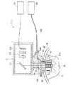
図1に示すように顕微鏡システム1は、架台2上にステージ3を有し、ステージ3の上方には、観察対象Wの正立像を比較的に広い視野で観察する双眼実体顕微鏡4が配置され、ステージ3と双眼実体顕微鏡4との間には、観察対象Wを相対的に高倍率で観察する顕微鏡(以下、マイクロ顕微鏡)5が進退自在に設けられている。The best mode for carrying out the present invention will be described in detail with reference to the drawings.
FIG. 1 shows a schematic configuration of the microscope system according to the first embodiment.
As shown in FIG. 1, the
双眼実体顕微鏡4は、対物レンズ11と接眼レンズ12とが取り付けられ、その内部に不図示のアフォーカルレンズ及び結像レンズなどが配設されている。接眼レンズ12は、左右の眼に対応して2つずつ設けられ、各々の接眼レンズ12の光軸が観察対象Wの表面で一致するように調整されている。さらに、この双眼実体顕微鏡4には、モニタ6に接続されたCCD(Charge Coupled Device)カメラ13が取り付けられている。なお、このCCDカメラ13及びモニタ6は、双眼実体顕微鏡4に必須の構成要素ではない。
このような双眼実体顕微鏡4は、多軸アーム8により支持されている。多軸アーム8は、双眼実体顕微鏡4を観察対象W(ステージ2)に対して平行移動させたり、近接又は離間させたりする。また、対物レンズ11と観察対象Wとの間にマイクロ顕微鏡5のヘッド部21を挿入するスペースが形成されている。The binocular stereomicroscope 4 has an
Such a binocular stereomicroscope 4 is supported by a multi-axis arm 8. The multi-axis arm 8 translates the binocular stereomicroscope 4 with respect to the observation target W (stage 2), and moves close to or away from the observation target W (stage 2). A space for inserting the
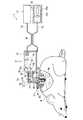
マイクロ顕微鏡5は、光学系を収容したヘッド部21が多軸の移動機構である多軸ステージ22に支持されている。ヘッド部21の下面には、対物レンズユニット23が取り付けられている。また、ヘッド部21には、光ファイバ24,25を介して光源26及び光検出器27が接続されている。各部の制御は、コントローラ28により行われ、観察像はモニタ7に表示される。さらに、対物レンズユニット23の先端を挿入して固定する対物レンズ挿入具51が、観察対象Wに取り付けられている。 In the
光源26には、例えば、アルゴンイオンレーザ、ヘリウムネオンレーザなどのレーザ発振器29aが用いられる。図2に示すように、光源26から発振するレーザビームの光路上には、集光レンズ29bと光ファイバ24の一端が、順番に配置され、集光レンズ29bで集光されたレーザビームを光ファイバ24に導入するようになっている。 As the
光ファイバ24の一端は、光源26に接続されて、他端は、ヘッド部21に接続されている。なお、この光ファイバ24は、一端から他端に至るまでの間に、光検出器27に接続された光ファイバ25と光ファイバカプラ30で接続されており、光ファイバ24を通る光を光ファイバ25に分波するようになっている。この光ファイバ25の一端は、光検出器27に接続されている。
光検出器27には、例えば、光電子倍増管や、PD(フォトダイオード)、CCDなど用いられている。この光検出器27に入力される光は、光源26から観察対象Wに照射された光の反射光又は蛍光光であって、光ファイバカプラ30から分波された光である。One end of the
For the
ヘッド部21のケース31には、光ファイバ24の他端に取り付けられたコネクタ32を固定する固定部33が設けられている。さらに、光ファイバ24から出射するレーザビームの光路上にはコリメータレンズ34と光スキャナ35が順番に配置されている。光スキャナ35は、レーザビームを2次元に走査するもので、例えば、レーザビームをX方向(観察対象Wの横方向)に走査させるガルバノミラーと、Y方向(観察対象Wの縦方向)に走査させるガルバノミラーとを組み合わせて構成されている。また、ケース31の下面で、光スキャナ35の下方に相当する位置には、レーザビームが通る窓36が設けられている。窓36の縁部は、下方に延出し、対物レンズユニット23を固定する装着部37をなしている。この装着部37には、嵌合用の溝や、ネジ溝などが形成されており、対物レンズユニット23を観察対象に固定したままで着脱できるようになっている。 The
図2及び図3に示すように、対物レンズユニット23は、枠部41内に複数の対物レンズ42を保持した構成を有している。枠部41は、その径を減少させるような段差を有し、ヘッド部21の装着部37に取り付けられる大径の枠基部43の先に、枠基部43よりも径が小さく、主に観察対象W内に挿入される枠先端部44が設けられている。なお、この段差は、枠基部43及び枠先端部44のそれぞれの外壁と、対物レンズユニット23の軸線C1(図3参照)に略直交する平面45とから構成されている。なお、この対物レンズユニット23は、枠部41の先端の被装着部46でヘッド部21に取り付けられ、観察対象Wに固定された対物レンズ挿入具51に挿入された状態で使用される。 As shown in FIGS. 2 and 3, the
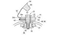
対物レンズ挿入具51は、挿入孔52に対物レンズユニット23を位置決めして固定する挿入具本体53を有している。挿入具本体53は、円形の基部54から、観察対象Wに挿入される挿入部55を延出させた構成を有し、前記挿入孔52がヘッド部21側の上面54aから、観察しようとする部位(図3に示す観察部位W1)に望む先端面55aに至るまで貫通している。この挿入孔52には、その開口径を縮小させる段差を有し、上面54a側の大径部57と、先端面55a側の小径部58とが形成されている。なお、この段差は、大径部57及び小径部58のそれぞれの内壁と、これを繋ぐ平面56とから構成されており、この平面56は、挿入孔52の軸線(図3の軸線C1)と略直交するように設けられている。 The objective
また、図2に示すように、基部54の側面54bには、挿入孔52に連通するネジ孔59が設けられており、ここにネジ60がねじ込まれている。
挿入部55は、基部54よりも縮径しており、挿入部55の先端には、係合部61が設けられている。係合部61は、挿入孔52の軸線C1(図3参照)と略直交する方向に突出している。また、係合部61の外側面には、先端面55aから基部54に向かって拡径するようなテーパが設けられている。そして、挿入部55には、先端面55a側から固定リング62が押し込まれる。
図3に示すように、固定リング62は、挿入具本体53を表皮W2、つまり観察対象Wに固定するための固定部材で、環形状をなしている。なお、固定リング62は、環形状の一部を切り欠いた形状を有しても良いし、U字形状であっても良い。As shown in FIG. 2, a
The
As shown in FIG. 3, the fixing
ここで、挿入具本体53の挿入孔52に対物レンズユニット23が挿入されると、平面45を平面56に当接させた状態では対物レンズユニット23の枠基部43が大径部57に収容され、枠先端部44が小径部58に収容される。そして、挿入孔52の平面56と枠部41の平面45とが当接し、対物レンズユニット23の高さ方向が位置決めされる。枠基部43及び枠先端部44の長さは、それぞれ大径部57及び小径部58よりも長い。したがって、枠基部43は、大径部58から上方に突出し、枠先端部44は、小径部58よりも観察部位W1側に突出する。
また、対物レンズユニット23は、観察対象Wの像を拡大する倍率に応じて、異なる対物レンズ42を組み合わせたものが複数用意されている。Here, when the
Further, a plurality of
なお、図1に示すように、マイクロ顕微鏡5のコントローラ28は、ヘッド部21(多軸ステージ22を含む)、光源26、光検出器27、及びマイクロ顕微鏡5用のモニタ7のそれぞれにケーブルで接続されている。例えば、光源26に対しては、レーザビームのON、OFFや出力の制御を行う。ヘッド部21に対しては、光スキャナ35(図2参照)をフィードバック制御する。また、光検出器27から検出信号を取得し、データ処理を行い、モニタ7に表示させる。さらに、マイクロ顕微鏡5が3次元観察を行う場合には、コリメータレンズ34を光スキャナ35に近づけたり、遠ざけたりする。
また、多軸ステージ22は、ヘッド部21を前後方向、左右方向、上下方向にそれぞれ平行移動させる電動のステージを組み合わせて構成されている。As shown in FIG. 1, the
The
次に、この顕微鏡システム1を用いて観察対象Wを観察する手順の一例について以下に説明する。
まず、図1に示すように、双眼実体顕微鏡4の視野下にあるステージ3上に、観察対象Wを置く。このとき、コントローラ28で多軸ステージ22を操作して、マイクロ顕微鏡5のヘッド部21を双眼実体顕微鏡4による観察を邪魔しない位置まで退避させておく。また、ヘッド部21が多軸ステージ22に取り付けられていない場合には、この段階でヘッド部21を多軸ステージ22に装着する。
そして、双眼実体顕微鏡4で、図3に示す観察部位W1の位置を確かめながら、観察対象Wの表皮W2を切り開く。この際、必要に応じて観察部位W1を蛍光色素で染めておく。Next, an example of a procedure for observing the observation object W using the
First, as shown in FIG. 1, the observation object W is placed on the stage 3 under the visual field of the binocular stereomicroscope 4. At this time, the
Then, the binocular stereomicroscope 4 cuts the skin W2 of the observation target W while confirming the position of the observation site W1 shown in FIG. At this time, the observation site W1 is dyed with a fluorescent dye as necessary.
観察対象Wの表皮W2を切り開いたら、観察対象Wの内部に固定リング62を挿入し、続いて挿入具本体53の挿入部55を表皮W2内に挿入する。そして、観察部位W1の上方に挿入孔52があることを確認してから、固定リング62を先端面55a側から挿入部55に押し込む。固定リング62が係合部61を越えると、固定リング62の上面と挿入本体具53の基部54の下面との間で表皮W2が挟み込まれ、対物レンズ挿入具51が表皮W2に固定される。 When the skin W2 of the observation target W is cut open, the fixing
ここまでの準備が終了したら、再びコントローラ28で多軸ステージ22を操作してマイクロ顕微鏡5のヘッド部21を観察部位の上方に移動させる。ヘッド部21、つまり対物レンズユニット23の先端の位置決めは、双眼実体顕微鏡4や、モニタ6で確認しながら行う。なお、図1には、モニタ6に表皮W2を切り開いた観察対象Wと、ヘッド部21及び対物レンズユニット23の像が表示された例が図示されている。
そして、ヘッド部21に固定されている対物レンズユニット23の枠部41の平面45が、対物レンズ挿入具51の挿入孔52の平面56に当接するまで、ヘッド部21を下降させる。When the preparation so far is completed, the
Then, the
平面45と平面56とが当接したら、対物レンズ挿入具51のネジ60を締め、ネジ60の先端を対物レンズユニット23の枠基部43に押し当て、対物レンズユニット23を対物レンズ挿入具51に固定する。これにより、対物レンズユニット23(及び対物レンズ42、以下同じ)が対物レンズ挿入具51を介して表皮W2、つまり観察対象Wに固定される。 When the
対物レンズユニット23を位置決めして観察対象Wに固定したら、コントローラ28を操作してレーザビームを出射させる。図2に示すように、レーザビームは、集光レンズ29bを通って光ファイバ24に導入され、ヘッド部21内に導かれる。ヘッド部21内では、光スキャナ35により走査され、コリメータレンズ34及び対物レンズ42で集光され、観察対象Wの所定位置に照射される。そして、観察対象Wで反射した光や、蛍光色素から発せられる蛍光は、同じ光学系を経て光ファイバ24に戻される。ここで、前述のように光ファイバ24は、その途中に光ファイバカプラ30を有するので、反射光や、蛍光は、光ファイバ25に分波し、光検出器27で検出される。そして、光検出器27は、光の強度に応じて電気信号をコントローラ28に出力する。 After the
ここで、光検出器27が出力する信号には、レーザビームが照射された領域の情報のみが含まれている。したがって、コントローラ28は、レーザビームを走査させた結果、得られる所定の面積分の情報を取り込んで画像処理を行い、モニタ7に出力する。モニタ7に表示された像は、必要に応じて紙媒体に出力されたり、磁気記録媒体に記録されたりする。
なお、レーザビームは、観察対象Wの内部に浸透しやすく、焦点深度が浅いので、コリメータレンズ34(図2参照)などでレーザビームの焦点位置を上下方向にずらすと、観察対象Wの内部の像が得られ、観察部位を3次元観察できる。Here, the signal output from the
Since the laser beam easily penetrates into the observation target W and has a shallow depth of focus, if the focal position of the laser beam is shifted in the vertical direction using a collimator lens 34 (see FIG. 2) or the like, An image is obtained, and the observation site can be observed three-dimensionally.
観察対象Wの経時変化を観察する場合には、ネジ60を緩めてからヘッド部21を引き上げて対物レンズユニット23を観察対象Wから外す。一方、対物レンズ挿入具51は、観察対象Wに固定したままにしておく。そして、再度、同じ観察部位W1を観察するときには、固定したままの対物レンズ挿入具51に対物レンズユニット23を挿入して固定し、観察を行う。 When observing a change with time of the observation target W, the
この実施の形態では、予め観察対象Wに固定した対物レンズ挿入具51を用いることで、観察対象Wに対して対物レンズユニット23を固定することができる。しかも、この対物レンズ挿入具51によれば、段差部(平面56)及びネジ60で対物レンズユニット23の深さ方向及び左右方向が位置決めされるので、観察対象Wに対する対物レンズユニット23の位置決めも可能になる。さらに、ネジ60を緩めると、対物レンズユニット23を対物レンズ挿入具51から簡単に取り外せるので、観察するとき以外には対物レンズユニット23を観察対象Wから取り外すことができる。 In this embodiment, the
また、このような対物レンズユニット23が取り付けられたマイクロ顕微鏡5は、対物レンズ42を所定位置に固定することができるので、観察対象の2次元観察や、3次元観察を精度良く行うことができるし、長期に渡る観察も可能になる。
そして、このようなマイクロ顕微鏡5を含む顕微鏡システム1は、観察位置を双眼実体顕微鏡4で確認しながら対物レンズユニット23を観察対象Wに固定することができるので、観察対象Wの2次元観察や、3次元観察を精度良く行うことができるし、長期に渡る観察も可能になる。Moreover, since the
The
なお、この実施の形態において、対物レンズ挿入具51の基部54及び挿入部55は、対物レンズユニット23の枠部41と同心円状に配置される円形状を有するが、これらは四角形状でも良いし、他の形状でも良い。また、ネジ孔59及びネジ60は、2組以上有しても良い。 In this embodiment, the
次に、本発明の第2の実施の形態について図面を参照しながら詳細に説明する。なお、前記各実施の形態と同一の構成要素には同一の符号を付している。また、前記各実施の形態と重複する説明は省略する。
この実施の形態の顕微鏡システムは、対物レンズの枠部がL字形状を有することを特徴とする。Next, a second embodiment of the present invention will be described in detail with reference to the drawings. In addition, the same code | symbol is attached | subjected to the component same as each said embodiment. Further, the description overlapping with each of the embodiments is omitted.
The microscope system according to this embodiment is characterized in that the frame portion of the objective lens has an L shape.
図4に示すように、対物レンズユニット73は、複数の対物レンズ42を保持する枠部74を有する。枠部74は、L字形状の枠基部75と、枠基部75から延びる枠先端部44とから構成されている。枠基部75は、枠先端部44に連なり、上方に延びる鉛直部76と、鉛直部76の上端付近から水平方向に延びる水平部77とから構成されている。また、水平部77の先端には、ヘッド部21に取り付ける際に用いる被装着部46が設けられている。このような対物レンズユニット73において、対物レンズ42は、枠先端部44と、鉛直部76と、水平部77とに振り分られて保持されており、さらに鉛直部76の軸線と水平部77の軸線とが交わる位置には光軸を90°折り曲げる折り曲げミラー78が保持されている。 As shown in FIG. 4, the
この対物レンズユニット73が取り付けられるヘッド部21は、ケース31の側面に窓36と装着部37とが設けられており、光ファイバ24を通じて導入されるレーザビームを集光するコンデンサレンズ34と、2つのガルバノミラー35a,35bとを備えている。2つのガルバノミラー35a,35bは、光スキャナ35を構成し、2次元に走査されたレーザビームが窓36から対物レンズユニット73に向けて出射されるように配置されている。 The
この対物レンズユニット73を用いて観察を行う際には、対物レンズ挿入具51を観察対象Wの表皮W2に固定した後に、双眼実体顕微鏡4で確認しながら対物レンズ挿入具51に対物レンズユニット73を挿入し、固定する。
そして、観察中は、水平部77の対物レンズ42を通ったレーザビームが折り曲げミラー78で下向きに折り曲げられ、鉛直部76及び枠先端部44の対物レンズ42を通り、観察対象Wの所定位置に集光させられる。When observing using the
During observation, the laser beam that has passed through the
この実施の形態によれば、対物レンズユニット73の枠部74が、ヘッド部21に装着される被装着部46から先端に至るまでの間で略直角に折り曲っているので、ヘッド部21を観察対象Wの側方に配置することができる。したがって、双眼実体顕微鏡4の視野をヘッド部21が遮ることがないので、対物レンズユニット73の挿入位置を確認し易くなる。また、前述のように、対物レンズ挿入具51を用いることにより、対物レンズユニット73及び対物レンズ42を観察対象Wに位置決めして固定できる。 According to this embodiment, since the
なお、枠部74が、L字型を有する対物レンズユニットの他の形態としては、図5に示すような対物レンズユニット83があげられる。
この対物レンズユニット83の枠部74は、前記枠基部75と枠先端部84とから構成されている。枠先端部84は、主に観察対象W内に挿入される部分である。枠先端部84の最も観察対象W側(下側)にある対物レンズ42の先には、折り曲げミラー85が設けられ、レーザビームを90°折り曲げるようになっている。さらに、枠先端部84の側面には、折り曲げミラー85で折り曲げたレーザビームを通過させる窓86が設けられている。As another form of the objective lens unit in which the
The
この対物レンズユニット83では、枠先端部84及び鉛直部76の軸線C1方向と交差する方向にある部位に光を集光させることができるので、そのような部位の観察が可能になる。折り曲げミラー85を軸線C1に対して45°傾けて保持すると水平方向にある部位を観察することができる。また、折り曲げミラー85と軸線C1のなす角を0°を越えて45°未満に設定すると、水平方向よりも下がった位置にある部位を観察できる。折り曲げミラー85と軸線C1のなす角を45°を越えて90°未満に設定すると、水平方向よりも上側にある部位を観察できる。 In the
次に、本発明の第3の実施の形態について図面を参照しながら詳細に説明する。なお、前記各実施の形態と同一の構成要素には同一の符号を付している。また、前記各実施の形態と重複する説明は省略する。
この実施の形態の顕微鏡システムは、対物レンズ挿入具に貫通孔を閉塞する蓋を設けたことを特徴とする。Next, a third embodiment of the present invention will be described in detail with reference to the drawings. In addition, the same code | symbol is attached | subjected to the component same as each said embodiment. Further, the description overlapping with each of the embodiments is omitted.
The microscope system of this embodiment is characterized in that a lid for closing the through hole is provided on the objective lens insertion tool.
図6に示すように、対物レンズ挿入具91は、挿入具本体53の基部54と固定リング62とで表皮W2に固定され、挿入孔52に対物レンズユニット23を挿入し、段差部(平面56)及びネジ60により対物レンズユニット23を位置決めして固定する構成を有している。 As shown in FIG. 6, the objective
さらに、基部54の上面54a近傍の側面54bには、細長形状で変形可能な板状部材(弾性部材)92が延出している。この板状部材92の先端には、挿入孔52の開口を閉塞する蓋93が取り付けられている。この蓋93は、板状部材92が取り付けられている基端から先端に向かって断面積を減少するようなテーパを有している。また、蓋93の基端において、板状部材92の反対側には、鍔部94が延設されており、指やピンセットで蓋93を掴み易くなっている。 Further, an elongated and deformable plate-like member (elastic member) 92 extends on the
この顕微鏡ユニット1は、前記のように双眼顕微鏡4で観察しながら、対物レンズ挿入具91を表皮W2に取り付ける。観察を行うときには、対物レンズユニット23を対物レンズ挿入具91の挿入孔52に挿入し、マイクロ顕微鏡5で2次元観察又は3次元観察を行う。そして、観察を行わないときには、対物レンズユニット23を挿入孔52から引き出し、図7に示すように、挿入孔52に蓋93を上面54a側から押し込んで挿入孔52を密閉させる。さらに、再度観察を行うときには、鍔部94などを掴んで蓋93を挿入孔52から引き抜き、対物レンズユニット23を挿入孔52に挿入する。 The
このような対物レンズ挿入具91によれば、挿入具本体53と固定リング62とで表皮W2を挟み込むことで、観察対象Wに対して対物レンズユニット23を位置決めして固定することが可能になる。さらに、対物レンズユニット23が挿入されていないときには、挿入孔52が蓋93で閉塞されるので、観察対象W内に異物が入ることを防止できる。また、このような対物レンズ挿入具91を有するマイクロ顕微鏡5や、顕微鏡システム1は、前述の第1の実施の形態と同様に、高精度の観察や、長期間の観察が可能になる。 According to such an objective
また、異物が入らないようにする蓋の他の形態としては、図8及び図9に示すような対物レンズ挿入具96があげられる。
この対物レンズ挿入具96は、挿入具本体53の挿入孔52内に蓋97が設けられている。この蓋97は、挿入孔52内に設けられた複数の弾性片98からなる。この弾性片98は、挿入孔52の大径部57の開口を塞ぐ弾性部材に、十文字の切り込み99を入れて形成されており、挿入孔52の内壁側の基部は内壁に一体に設けられている。なお、切り込み99は、一文字でも、放射状でも良い。As another form of the lid for preventing foreign matter from entering, there is an objective
The objective
対物レンズユニット23が挿入されない状態では、弾性片98の切り込み99側の周縁部が互いに接し、挿入孔52が塞がれるので、挿入孔52を通じて観察対象W内に異物が侵入することを防止できる。
図10に示すように、挿入孔52に対物レンズユニット23が挿入されると、弾性片98は、対物レンズユニット23の枠部41に押されて下方に湾曲し、弾性片98の周縁部の間が開き、対物レンズユニット23を挿入可能な開口が形成される。そして、対物レンズユニット23を挿入した状態では、変形させられた弾性片98が対物レンズユニット23の枠部41に接触するので、対物レンズユニット23をさらに確実に位置決めして固定することが可能になる。In a state where the
As shown in FIG. 10, when the
次に、本発明の第4の実施の形態について図面を参照しながら詳細に説明する。なお、前記各実施の形態と同一の構成要素には同一の符号を付している。また、前記各実施の形態と重複する説明は省略する。
この実施の形態の顕微鏡システムは、図11又は図12に示すように、対物レンズユニット23を微動させる機構を備えることを特徴とする。Next, a fourth embodiment of the present invention will be described in detail with reference to the drawings. In addition, the same code | symbol is attached | subjected to the component same as each said embodiment. Further, the description overlapping with each of the embodiments is omitted.
As shown in FIG. 11 or FIG. 12, the microscope system according to this embodiment includes a mechanism for finely moving the
図11に示すように、対物レンズ挿入具101は、観察対象Wの表皮W2を固定リング62と固定部102とで挟み込み、固定部102に対して微動可能な微動部103に対物レンズユニット23を挿入するように構成されている。
固定部102は、前記実施の形態と同様の機能を有する基部104と挿入部105とを有し、中央に微動部103を挿入する貫通孔106が形成されている。貫通孔106は、上面104aと先端面105aとにそれぞれ開口を有し、段差により上面104a側の大径部107と、先端面105a側の小径部108とが形成されている。なお、段差は、大径部107の内壁及び小径部108の内壁と、貫通孔106の軸線に略直交する平面109とから形成されている。そして、この平面109には、微動部103の底面103aが当接する。
また、基部104の側面104bからねじ込まれる微動ツマミ110の先端は、微動部103の側壁に当接している。さらに、貫通孔106の内壁であって、微動ツマミ110の先端と対向する位置には、押圧部材(コイルバネ)111の一端が固定されており、押圧部材111の他端は微動部103の側壁に固定されている。As shown in FIG. 11, the objective
The fixing
Further, the tip of
微動部103は、その内部に対物レンズユニット23を挿入する挿入孔52が形成されており、挿入孔52の平面56に対物レンズユニット23の平面45が当接する。さらに、この挿入孔52には、複数の凹部112が設けられており、その各々にコイルスプリングなどの弾性部材113によって挿入孔52の軸線に向かって付勢されたボール114が収容されている。
なお、対物レンズユニット23の枠部41には、ボール114の位置に合わせて凹形状の係合溝115が形成されている。The
A
この対物レンズ挿入具101を使用する際には、最初に、固定リング62と基部104とで表皮2を挟み込んで観察対象Wに固定する。この状態で微動部103の挿入孔52に対物レンズユニット23を挿入すると、対物レンズユニット23の枠部41の係合溝115にボール114が係合し、対物レンズユニット23が微動部103の所定位置に固定される。
対物レンズユニット23の位置を横方向、又は縦方向に微調整する場合には、微動ツマミ110を回転させる。微動ツマミ110を押し込むと、微動部103が押圧部材111を押し潰す方向に移動し、微動部103に固定されている対物レンズユニット23も同じ方向に移動する。一方、微動ツマミ110を戻すと、押圧部材111が復元し、押圧部材111が伸びる方向に微動部103が移動させられ、微動部103に固定されている対物レンズユニット23も同じ方向に移動する。
このようにして対物レンズユニット23の位置を微調整してから、前述のようにマイクロ顕微鏡5で2次元又は3次元観察を行う。When the objective
When finely adjusting the position of the
After finely adjusting the position of the
この対物レンズ挿入具101によれば、対物レンズユニット23を微動部103及び固定部102を介して観察対象Wに固定することができる。さらに、微動ツマミ110及び押圧部材111からなる微動機構で、微動部103を固定部102に対して平行移動させることで、対物レンズユニット23の位置を微調整することができる。なお、図11には、1組の微動ツマミ110及び押圧部材111のみが図示されているが、直交する位置に2組の微動ツマミ110及び押圧部材111を設けると、縦横(XY方向)に対物レンズユニット23の微調整が可能になる。
また、このような対物レンズ挿入具101を含むマイクロ顕微鏡5や、顕微鏡システム1は、前述の第1の実施の形態と同様に、高精度の観察や、長期間の観察が可能になる。According to the objective
In addition, the
さらに、図12に示す対物レンズ挿入具121のように、上下方向に対物レンズユニット23を微動させることもできる。
この対物レンズ挿入具121は、固定部102の貫通孔106に微動部103を挿入した構成を有する。貫通孔106の平面109には、押圧部材111の一端が固定され、微動部103の底面103aには、押圧部材111の他端が固定されている。さらに、固定部102の基部104の一部が、貫通孔106の軸線に向かって延出し、微動ツマミ110を回転自在に支持する支持部122が形成されている。微動ツマミ110は、微動部103を鉛直下方に押圧するもので、その先端は微動部103の上面に当接している。Further, as in the objective
The objective
この対物レンズ挿入具121において、微動ツマミ110を回転させながら押し込むと、押圧部材111が押し潰されて微動部103が下降する。一方、微動ツマミ110を回転させて戻すと、押圧部材111が微動部103を押し上げ、微動部103が上昇する。そして、対物レンズユニット23の位置を微調整した後に、前述のようにマイクロ顕微鏡5で2次元又は3次元観察を行う。 In this objective
このような対物レンズ挿入具121を用いると、対物レンズユニット23の上下方向の微調整が可能になるので、例えば、観察部位の表面にレーザビームを集光する場合や、3次元観察を行う場合などに作業が容易になる。ここで、微動ツマミ110及び押圧部材111からなる微動機構のみで対物レンズユニット23の焦点合わせをしても良いし、ヘッド部21の光学系による焦点合わせを併用しても良い。対物レンズ挿入具121の微動機構のみを用いる場合には、ヘッド部21の構成を簡略化できる。
なお、図11に示すような水平方向の微動機構と、図12に示すような上下方向の微動機構とを組み合わせると、縦横及び上下に対物レンズユニット23を微調整できるようになる。When such an objective
When the fine movement mechanism in the horizontal direction as shown in FIG. 11 and the fine movement mechanism in the vertical direction as shown in FIG. 12 are combined, the
なお、対物レンズユニット23と観察対象Wとの間に水などの液体を注入し、液体の量を増減させて光の焦点調整を行っても良い。例えば、図3に示すような対物レンズ挿入具51の場合に、挿入部54を対物レンズユニット23の先端よりも観察部位W1側に突出する長さにする。さらに、挿入孔52と対物レンズユニット23との間に、液体が通流可能な隙間を形成しておく。そして、この隙間には、液体を給排するポンプ(注射器でも良い)に接続されたチューブが挿入される。
観察時には、挿入部54を観察部位W1の周囲に密着させてから表皮W2に対物レンズ挿入具を固定する。観察部位W1は、挿入孔52と対物レンズユニット23とで形成される空間により密閉されるので、この空間に液体を注入すると、空気と液体の密度の違いから焦点位置が対物レンズユニット23側に変化する。そこで、モニタ7に表示される像を確認しながら、液体の量を増加したり、減少させたりして焦点位置を変化させる。
このような対物レンズ挿入具によれば、対物レンズを観察部位に位置決めして固定することができると共に、その焦点位置を調整することができる。なお、挿入部の先端からの液体の漏洩を抑制するために、挿入部の先端に液蜜性のパッキンなどを取り付けると良い。Note that liquid focus adjustment may be performed by injecting a liquid such as water between the
At the time of observation, the
According to such an objective lens insertion tool, the objective lens can be positioned and fixed at the observation site, and the focal position can be adjusted. In addition, in order to suppress the leakage of the liquid from the tip of the insertion portion, it is preferable to attach a liquid-tight packing or the like to the tip of the insertion portion.
次に、本発明の第5の実施の形態について図面を参照しながら詳細に説明する。なお、前記各実施の形態と同一の構成要素には同一の符号を付している。また、前記各実施の形態と重複する説明は省略する。
この実施の形態の顕微鏡システムは、対物レンズなどを挿入可能な孔を2つ以上有することを特徴とする。Next, a fifth embodiment of the present invention will be described in detail with reference to the drawings. In addition, the same code | symbol is attached | subjected to the component same as each said embodiment. Further, the description overlapping with each of the embodiments is omitted.
The microscope system of this embodiment has two or more holes into which an objective lens or the like can be inserted.
図13に示すように、対物レンズ挿入具131は、固定リング62と挿入具本体53とから構成され、挿入具本体53に第1挿入孔132と第2挿入孔133とが平行に設けられている。
第1挿入孔132及び第2挿入孔133は、挿入具本体53の高さ方向に沿った中心軸C2から外れた位置に設けられ、挿入具本体53の基部54及び挿入部55を貫通し、互いに平行な軸線を有している。さらに、第1挿入孔132と第2挿入孔133とは、それぞれ大径部57及び小径部58を有している。
基部54には、側面から第1挿入孔132まで貫通するネジ孔59が穿設されており、ここに第1挿入孔132内の対物レンズユニット23を固定するためのネジ60がねじ込まれている。同様に、基部54の側面から第2挿入孔133まで貫通するネジ孔59が穿設されており、このネジ孔59には第2挿入孔133内の対物レンズユニット23を固定するためのネジ60がねじ込まれている。
なお、挿入孔の数は、2つに限定されず、3つ以上でも良い。この場合には、挿入孔の数に応じてネジ孔59及びネジ60が設けられる。ネジ孔59及びネジ60は、1つの挿入孔132,133に対して複数設けられても良い。As shown in FIG. 13, the objective
The first insertion hole 132 and the
A
The number of insertion holes is not limited to two and may be three or more. In this case, screw holes 59 and screws 60 are provided according to the number of insertion holes. A plurality of screw holes 59 and screws 60 may be provided for one
観察対象Wを観察する際には、最初に、対物レンズ挿入具131を観察対象Wに位置決めして固定する。この際に、2つの挿入孔132,133が観察しようとする部位の上方に位置するように、双眼実体顕微鏡4で確認する。さらに、各挿入孔132,133に対物レンズユニット23を挿入し、それぞれをネジ60で固定する。観察が終了したり、対物レンズユニット23を交換したりする際には、ネジ60を緩めて挿入孔132,133に挿入されている対物レンズユニット23を対物レンズ挿入具131から取り外す。各挿入孔132,133に挿入される対物レンズユニット23は、異なる倍率のものでも、同じ倍率のものでも良い。 When observing the observation target W, first, the objective
この対物レンズ挿入具131によれば、観察しようとする部位が近接する場合に、1つの対物レンズ挿入具131で、対物レンズユニット23を位置決めをして固定することができる。観察対象Wが、小動物などのように、複数の対物レンズ挿入具を取り付けることが困難な場合でも、精度の良い観察が可能になる。 According to the objective
なお、各挿入孔132,133に、図6に示すような蓋93を設けると、挿入孔132,133から対物レンズユニット23を取り外しても、挿入孔132,133から観察対象W内部に異物が侵入することを防止できる。ここで、蓋93は一方の挿入孔132,133のみに設けても良い。 In addition, if a
次に、本発明の第6の実施の形態について図面を参照しながら詳細に説明する。なお、前記各実施の形態と同一の構成要素には同一の符号を付している。また、前記各実施の形態と重複する説明は省略する。
この実施の形態の顕微鏡システムは、対物レンズなどを挿入する挿入孔の他に、対物レンズの挿入以外に用いる孔が設けられていることを特徴とする。Next, a sixth embodiment of the present invention will be described in detail with reference to the drawings. In addition, the same code | symbol is attached | subjected to the component same as each said embodiment. Further, the description overlapping with each of the embodiments is omitted.
The microscope system according to this embodiment is characterized in that, in addition to an insertion hole for inserting an objective lens or the like, a hole used other than the insertion of the objective lens is provided.
図14に示すように、対物レンズ挿入具141の挿入孔52は、大径部57及び小径部58を有し、平面56とネジ60により対物レンズユニット23を固定するように構成されている。処置孔142は、中心軸C2と平行な軸線に沿って基部54及び先端部55を貫通し、その内径は略均一である。処置孔142の上側の開口143の周縁は、基部54が中心軸C2に沿って上方に突出し、環状凸部144になっている。この環状凸部144は、処置具の固定や、ガイドに用いられる。また、基部54の上面54a近傍の側面には屈曲自在な板状部材92が一体的に設けられ、この板状部材92の先端には、環状凸部144に嵌合し、開口143を密閉する蓋93が一体的に取り付けられている。なお、環状凸部144の外側面に、周方向に沿って凹溝や、凸溝を設け、処置具を固定し易くしても良い。 As shown in FIG. 14, the
この顕微鏡システム1では、対物レンズ挿入具141を位置決めしてから観察対象Wに固定する。さらに、挿入孔52に対物レンズユニット23を挿入して固定し、環状凸部144に嵌合している蓋93を外す。観察部位W1が、他の臓器などで隠れている場合には、処置孔142からバスケットを挿入し、観察対象W内部でバスケットを開かせて観察対象W内部を押し開き、観察部位W1を対物レンズユニット23で観察可能に露出させる。
また、図15に示すように、環状凸部144にシース145を装着し、観察対象W内部に空気を供給すると、空気により観察部位W1の周囲を広げることができる。また、シース145から薬剤を送ると、観察部位W1やその周囲の炎症などを防止できる。
このように、処置孔142を利用することで、観察部位W1の観察が確実に行えるようになる。また、観察部位W1や、その周囲に必要な処置を施すことが可能になる。なお、処置孔142に装着又は挿入される処置具は、前述のものに限定されずに、カテーテルや、鉗子などでも良い。In this
Further, as shown in FIG. 15, when the
Thus, by using the
次に、本発明の第7の実施の形態について図面を参照しながら詳細に説明する。なお、前記各実施の形態と同一の構成要素には同一の符号を付している。また、前記各実施の形態と重複する説明は省略する。
図16に示すように、顕微鏡システム1のマイクロ顕微鏡5は、観察部位W1を照らす光源26を有し、対物レンズユニット23が取り付けられるヘッド部21には、折り曲げミラー151と、結像光学系152と、CCD153とが配置されている。CCD153は、コントローラ28に接続されており、CCD153に取り込まれた観察部位W1の像がモニタ7(図1参照)に出力される。ここで、光源26には、光ファイバ束からなるライトガイド150が接続されている。Next, a seventh embodiment of the present invention will be described in detail with reference to the drawings. In addition, the same code | symbol is attached | subjected to the component same as each said embodiment. Further, the description overlapping with each of the embodiments is omitted.
As shown in FIG. 16, the
対物レンズ挿入具154は、挿入具本体53と固定リング62とからなる。挿入具本体53の中心には、上下方向の軸線に沿って挿入孔52が形成され、ここに対物レンズユニット23が挿入される。さらに、挿入具本体53において、ネジ孔59が形成されている部位と反対側の部位には、挿入具本体53の中心軸(つまり対物レンズユニット23の光軸)に対してライトガイド150の先端を挿入するライトガイド孔155が設けられている。ライトガイド孔155の開口は、基部54の上面54aと、挿入部55の先端面55aで、かつ挿入孔52の開口の近傍の位置とに設けられている。なお、ライトガイド孔155は、観察部位W1側(下側)が挿入具本体53の中心軸に向かうように傾斜していても良い。 The objective
このような対物レンズ挿入具154を用いると、対物レンズユニット23を観察対象Wに位置決めして固定することができる。さらに、観察部位W1の近傍に、ライトガイド150の先端を配置できるので、観察部位W1を明るく照らし、鮮明な観察像を得ることができる。
なお、基部54の上面54aに、ライトガイド孔155の開口を設ける代わりに、基部54の側面にライトガイド孔155の開口を設けても良い。さらに、ライトガイド孔155は、緩やかな湾曲を有しても良いし、直線形状でも良い。When such an objective
Instead of providing the opening of the
また、図17に示すように、対物レンズユニット161の枠部162に、ライトガイド孔155を設けても良い。枠部162は、複数の対物レンズ42を保持する孔163と、ライトガイド167を挿通させるライトガイド孔155aとを有し、これらの孔155a,163は共に枠部162の長さ方向の軸線に平行に設けられている。
一方、マイクロ顕微鏡5のヘッド部21の側面には、ライトガイド150の外径に等しい孔165が設けられている。また、ヘッド部21の装着部37の内側には、窓36に近接した位置にライトガイド150の外径に等しい孔166が設けられている。マイクロ顕微鏡5の光源26に接続されたライトガイド150は、孔165からヘッド部21内に引き込まれ、孔166内に挿入される。孔166は、ライトガイド150の光がヘッド部21の内部に漏れないように固定する。In addition, as illustrated in FIG. 17, a
On the other hand, a
この顕微鏡システム1は、ヘッド部21に対物レンズユニット161を取り付ける際には、孔166とライトガイド孔155aとが連通するように固定する。そして、観察対象Wに位置決めして固定された対物レンズ挿入具51の挿入孔52に対物レンズユニット161を挿入し、平面56とネジ60とで固定する。観察の際には、光源26からの光がライトガイド150を通じ、孔166からライトガイド孔155aに導かれる。そして、ライトガイド孔155a内のライトガイド167の先端の開口から観察対象W1に向けて照射される。
なお、ライトガイド150をライトガイド孔155a内に引き入れ、ライトガイド150で直接に観察部位W1を照らすようにしても良い。この場合には、ライトガイド150を予め孔166から引き出しておき、ライトガイド孔155a内に入れてから対物レンズユニット161をヘッド部21に固定する。
この実施の形態によれば、対物レンズユニット161の対物レンズ42の近傍から光を照射できるので、影などができ難く、観察部位W1を確実に照らすことができる。When attaching the
The
According to this embodiment, since light can be irradiated from the vicinity of the
なお、本発明は前記の各実施の形態に限定されずに広く応用することができる。
例えば、実施の形態のマイクロ顕微鏡5は、共焦点レーザ走査型顕微鏡として説明したが、ライトガイドで観察部位を照明し観察対象Wの像をCCDで撮るタイプの顕微鏡であっても良く、前述と同様の作用及び効果が得られる。
また、各実施の形態を組み合わせても良い。例えば、図11、図12に示すような、微動部103を有する対物レンズ挿入具101,121や、図16の示すような、ライトガイド孔155を有する対物レンズ挿入具154に、蓋93(図6参照)や、蓋97(図8)参照を設けても良い。The present invention is not limited to the above embodiments and can be widely applied.
For example, although the
Moreover, you may combine each embodiment. For example, as shown in FIGS. 11 and 12, the objective
1 顕微鏡システム
2 ステージ
4 双眼実体顕微鏡(実体顕微鏡)
5 マイクロ顕微鏡(顕微鏡)
23,73,83,161 対物レンズユニット
26 光源
27 光検出器
42 対物レンズ
51,91,96,101,121,131,141,154 対物レンズ挿入具
52,132,133,163 挿入孔
53 挿入具本体(本体)
54 挿入部
62 固定リング(固定部材)
92 板状部材(弾性部材)
93,97 蓋
99 切り込み
103 微動部
142 挿入孔
155,155a ライトガイド孔
W 観察対象
W2 表皮
1
5 Microscope (microscope)
23, 73, 83, 161
54
92 Plate member (elastic member)
93,97
Claims (12)
Translated fromJapanese前記挿入部に嵌合可能で、前記基部との間で前記表皮を挟み込む固定部材と、
を有することを特徴とする対物レンズ挿入具。An insertion portion that is inserted into the observation target is extended from a base that abuts the epidermis of the observation target, and an insertion hole that can be inserted by positioning an objective lens used for observing the inside of the observation target is provided. The body,
A fixing member that can be fitted to the insertion portion and sandwiches the skin between the base portion,
An objective lens insertion tool characterized by comprising:
The microscope according to any one of claims 9 to 11 is attached to a multi-axis moving mechanism, and configured to be movable forward and backward with respect to a stage on which the observation target is placed, and an entity above the stage. A microscope system characterized by arranging a microscope.
Priority Applications (5)
| Application Number | Priority Date | Filing Date | Title |
|---|---|---|---|
| JP2003357577AJP2005121947A (en) | 2003-10-17 | 2003-10-17 | Object lens insertion fixture, microscope and microscope system |
| EP04024276AEP1524542B1 (en) | 2003-10-17 | 2004-10-12 | Objective lens insertion tool & objective optical system attachment device |
| DE602004014697TDE602004014697D1 (en) | 2003-10-17 | 2004-10-12 | Objective insertion device, fastening device for a lens system |
| US10/964,866US20050094260A1 (en) | 2003-10-17 | 2004-10-14 | Objective lens unit, objective lens insertion tool, microscope, objective optical system fixing device, and microscope system |
| US11/642,436US20070097494A1 (en) | 2003-10-17 | 2006-12-20 | Objective lens unit, objective lens insertion tool, microscope, objective optical system fixing device, and microscope system |
Applications Claiming Priority (1)
| Application Number | Priority Date | Filing Date | Title |
|---|---|---|---|
| JP2003357577AJP2005121947A (en) | 2003-10-17 | 2003-10-17 | Object lens insertion fixture, microscope and microscope system |
Publications (1)
| Publication Number | Publication Date |
|---|---|
| JP2005121947Atrue JP2005121947A (en) | 2005-05-12 |
Family
ID=34614431
Family Applications (1)
| Application Number | Title | Priority Date | Filing Date |
|---|---|---|---|
| JP2003357577APendingJP2005121947A (en) | 2003-10-17 | 2003-10-17 | Object lens insertion fixture, microscope and microscope system |
Country Status (1)
| Country | Link |
|---|---|
| JP (1) | JP2005121947A (en) |
Cited By (58)
| Publication number | Priority date | Publication date | Assignee | Title |
|---|---|---|---|---|
| WO2008044492A1 (en)* | 2006-10-13 | 2008-04-17 | Olympus Corporation | Method of microscopically observing the inside of small animal's body |
| WO2009058967A1 (en)* | 2007-10-31 | 2009-05-07 | Ethicon Endo-Surgery, Inc | Detachable distal overtube section and methods for forming a sealable opening in the wall of an organ |
| US7655004B2 (en) | 2007-02-15 | 2010-02-02 | Ethicon Endo-Surgery, Inc. | Electroporation ablation apparatus, system, and method |
| US7699477B2 (en) | 2006-08-25 | 2010-04-20 | Olympus Corporation | Alignment method, alignment apparatus, and alignment screen for objective-lens guiding device |
| US7787178B2 (en) | 2006-08-25 | 2010-08-31 | Olympus Corporation | Objective-lens guiding device and objective lens unit |
| US7815662B2 (en) | 2007-03-08 | 2010-10-19 | Ethicon Endo-Surgery, Inc. | Surgical suture anchors and deployment device |
| US8037591B2 (en) | 2009-02-02 | 2011-10-18 | Ethicon Endo-Surgery, Inc. | Surgical scissors |
| US8070759B2 (en) | 2008-05-30 | 2011-12-06 | Ethicon Endo-Surgery, Inc. | Surgical fastening device |
| US8075572B2 (en) | 2007-04-26 | 2011-12-13 | Ethicon Endo-Surgery, Inc. | Surgical suturing apparatus |
| US8100922B2 (en) | 2007-04-27 | 2012-01-24 | Ethicon Endo-Surgery, Inc. | Curved needle suturing tool |
| US8114072B2 (en) | 2008-05-30 | 2012-02-14 | Ethicon Endo-Surgery, Inc. | Electrical ablation device |
| US8114119B2 (en) | 2008-09-09 | 2012-02-14 | Ethicon Endo-Surgery, Inc. | Surgical grasping device |
| US8157834B2 (en) | 2008-11-25 | 2012-04-17 | Ethicon Endo-Surgery, Inc. | Rotational coupling device for surgical instrument with flexible actuators |
| US8172772B2 (en) | 2008-12-11 | 2012-05-08 | Ethicon Endo-Surgery, Inc. | Specimen retrieval device |
| US8211125B2 (en) | 2008-08-15 | 2012-07-03 | Ethicon Endo-Surgery, Inc. | Sterile appliance delivery device for endoscopic procedures |
| US8241204B2 (en) | 2008-08-29 | 2012-08-14 | Ethicon Endo-Surgery, Inc. | Articulating end cap |
| US8252057B2 (en) | 2009-01-30 | 2012-08-28 | Ethicon Endo-Surgery, Inc. | Surgical access device |
| US8262655B2 (en) | 2007-11-21 | 2012-09-11 | Ethicon Endo-Surgery, Inc. | Bipolar forceps |
| US8262680B2 (en) | 2008-03-10 | 2012-09-11 | Ethicon Endo-Surgery, Inc. | Anastomotic device |
| US8262563B2 (en) | 2008-07-14 | 2012-09-11 | Ethicon Endo-Surgery, Inc. | Endoscopic translumenal articulatable steerable overtube |
| US8317806B2 (en) | 2008-05-30 | 2012-11-27 | Ethicon Endo-Surgery, Inc. | Endoscopic suturing tension controlling and indication devices |
| US8337394B2 (en) | 2008-10-01 | 2012-12-25 | Ethicon Endo-Surgery, Inc. | Overtube with expandable tip |
| US8353487B2 (en) | 2009-12-17 | 2013-01-15 | Ethicon Endo-Surgery, Inc. | User interface support devices for endoscopic surgical instruments |
| US8361066B2 (en) | 2009-01-12 | 2013-01-29 | Ethicon Endo-Surgery, Inc. | Electrical ablation devices |
| US8361112B2 (en) | 2008-06-27 | 2013-01-29 | Ethicon Endo-Surgery, Inc. | Surgical suture arrangement |
| US8403926B2 (en) | 2008-06-05 | 2013-03-26 | Ethicon Endo-Surgery, Inc. | Manually articulating devices |
| US8409200B2 (en) | 2008-09-03 | 2013-04-02 | Ethicon Endo-Surgery, Inc. | Surgical grasping device |
| US8480689B2 (en) | 2008-09-02 | 2013-07-09 | Ethicon Endo-Surgery, Inc. | Suturing device |
| US8496574B2 (en) | 2009-12-17 | 2013-07-30 | Ethicon Endo-Surgery, Inc. | Selectively positionable camera for surgical guide tube assembly |
| US8506564B2 (en) | 2009-12-18 | 2013-08-13 | Ethicon Endo-Surgery, Inc. | Surgical instrument comprising an electrode |
| US8529563B2 (en) | 2008-08-25 | 2013-09-10 | Ethicon Endo-Surgery, Inc. | Electrical ablation devices |
| US8568410B2 (en) | 2007-08-31 | 2013-10-29 | Ethicon Endo-Surgery, Inc. | Electrical ablation surgical instruments |
| US8579897B2 (en) | 2007-11-21 | 2013-11-12 | Ethicon Endo-Surgery, Inc. | Bipolar forceps |
| US8608652B2 (en) | 2009-11-05 | 2013-12-17 | Ethicon Endo-Surgery, Inc. | Vaginal entry surgical devices, kit, system, and method |
| US8652150B2 (en) | 2008-05-30 | 2014-02-18 | Ethicon Endo-Surgery, Inc. | Multifunction surgical device |
| US8679003B2 (en) | 2008-05-30 | 2014-03-25 | Ethicon Endo-Surgery, Inc. | Surgical device and endoscope including same |
| US8771260B2 (en) | 2008-05-30 | 2014-07-08 | Ethicon Endo-Surgery, Inc. | Actuating and articulating surgical device |
| US8828031B2 (en) | 2009-01-12 | 2014-09-09 | Ethicon Endo-Surgery, Inc. | Apparatus for forming an anastomosis |
| US8888792B2 (en) | 2008-07-14 | 2014-11-18 | Ethicon Endo-Surgery, Inc. | Tissue apposition clip application devices and methods |
| US8906035B2 (en) | 2008-06-04 | 2014-12-09 | Ethicon Endo-Surgery, Inc. | Endoscopic drop off bag |
| US8939897B2 (en) | 2007-10-31 | 2015-01-27 | Ethicon Endo-Surgery, Inc. | Methods for closing a gastrotomy |
| US8986199B2 (en) | 2012-02-17 | 2015-03-24 | Ethicon Endo-Surgery, Inc. | Apparatus and methods for cleaning the lens of an endoscope |
| US9005198B2 (en) | 2010-01-29 | 2015-04-14 | Ethicon Endo-Surgery, Inc. | Surgical instrument comprising an electrode |
| US9028483B2 (en) | 2009-12-18 | 2015-05-12 | Ethicon Endo-Surgery, Inc. | Surgical instrument comprising an electrode |
| US9049987B2 (en) | 2011-03-17 | 2015-06-09 | Ethicon Endo-Surgery, Inc. | Hand held surgical device for manipulating an internal magnet assembly within a patient |
| US9078662B2 (en) | 2012-07-03 | 2015-07-14 | Ethicon Endo-Surgery, Inc. | Endoscopic cap electrode and method for using the same |
| US9226772B2 (en) | 2009-01-30 | 2016-01-05 | Ethicon Endo-Surgery, Inc. | Surgical device |
| US9233241B2 (en) | 2011-02-28 | 2016-01-12 | Ethicon Endo-Surgery, Inc. | Electrical ablation devices and methods |
| US9254169B2 (en) | 2011-02-28 | 2016-02-09 | Ethicon Endo-Surgery, Inc. | Electrical ablation devices and methods |
| US9277957B2 (en) | 2012-08-15 | 2016-03-08 | Ethicon Endo-Surgery, Inc. | Electrosurgical devices and methods |
| US9314620B2 (en) | 2011-02-28 | 2016-04-19 | Ethicon Endo-Surgery, Inc. | Electrical ablation devices and methods |
| US9427255B2 (en) | 2012-05-14 | 2016-08-30 | Ethicon Endo-Surgery, Inc. | Apparatus for introducing a steerable camera assembly into a patient |
| US9545290B2 (en) | 2012-07-30 | 2017-01-17 | Ethicon Endo-Surgery, Inc. | Needle probe guide |
| US9572623B2 (en) | 2012-08-02 | 2017-02-21 | Ethicon Endo-Surgery, Inc. | Reusable electrode and disposable sheath |
| US10092291B2 (en) | 2011-01-25 | 2018-10-09 | Ethicon Endo-Surgery, Inc. | Surgical instrument with selectively rigidizable features |
| US10098527B2 (en) | 2013-02-27 | 2018-10-16 | Ethidcon Endo-Surgery, Inc. | System for performing a minimally invasive surgical procedure |
| US10314649B2 (en) | 2012-08-02 | 2019-06-11 | Ethicon Endo-Surgery, Inc. | Flexible expandable electrode and method of intraluminal delivery of pulsed power |
| US10779882B2 (en) | 2009-10-28 | 2020-09-22 | Ethicon Endo-Surgery, Inc. | Electrical ablation devices |
Citations (10)
| Publication number | Priority date | Publication date | Assignee | Title |
|---|---|---|---|---|
| JPS58115749U (en)* | 1982-01-29 | 1983-08-08 | 株式会社リコー | imaging device |
| JPH04107411A (en)* | 1990-08-28 | 1992-04-08 | Scala Kk | Enlarging observation device |
| JPH07163577A (en)* | 1993-12-10 | 1995-06-27 | Olympus Optical Co Ltd | Tracheal |
| JPH07275252A (en)* | 1992-06-30 | 1995-10-24 | Ethicon Inc | Port for flexible endoscope operation |
| JPH08117181A (en)* | 1994-08-29 | 1996-05-14 | Olympus Optical Co Ltd | Sheath for endoscope |
| JPH1147081A (en)* | 1997-08-05 | 1999-02-23 | Olympus Optical Co Ltd | Sheath for endoscope |
| JP2000510362A (en)* | 1996-05-03 | 2000-08-15 | エス. グリーン、フィリップ | System and method for endoscopic imaging and endoscopic surgery |
| JP2001231786A (en)* | 2000-02-22 | 2001-08-28 | Olympus Optical Co Ltd | Trocar mantle tube |
| JP2002224129A (en)* | 2001-02-02 | 2002-08-13 | Hakko Medical:Kk | Trocar fixing tool |
| JP2003116874A (en)* | 2001-10-10 | 2003-04-22 | Olympus Optical Co Ltd | Surgical microscope system |
- 2003
- 2003-10-17JPJP2003357577Apatent/JP2005121947A/enactivePending
Patent Citations (10)
| Publication number | Priority date | Publication date | Assignee | Title |
|---|---|---|---|---|
| JPS58115749U (en)* | 1982-01-29 | 1983-08-08 | 株式会社リコー | imaging device |
| JPH04107411A (en)* | 1990-08-28 | 1992-04-08 | Scala Kk | Enlarging observation device |
| JPH07275252A (en)* | 1992-06-30 | 1995-10-24 | Ethicon Inc | Port for flexible endoscope operation |
| JPH07163577A (en)* | 1993-12-10 | 1995-06-27 | Olympus Optical Co Ltd | Tracheal |
| JPH08117181A (en)* | 1994-08-29 | 1996-05-14 | Olympus Optical Co Ltd | Sheath for endoscope |
| JP2000510362A (en)* | 1996-05-03 | 2000-08-15 | エス. グリーン、フィリップ | System and method for endoscopic imaging and endoscopic surgery |
| JPH1147081A (en)* | 1997-08-05 | 1999-02-23 | Olympus Optical Co Ltd | Sheath for endoscope |
| JP2001231786A (en)* | 2000-02-22 | 2001-08-28 | Olympus Optical Co Ltd | Trocar mantle tube |
| JP2002224129A (en)* | 2001-02-02 | 2002-08-13 | Hakko Medical:Kk | Trocar fixing tool |
| JP2003116874A (en)* | 2001-10-10 | 2003-04-22 | Olympus Optical Co Ltd | Surgical microscope system |
Cited By (82)
| Publication number | Priority date | Publication date | Assignee | Title |
|---|---|---|---|---|
| US7699477B2 (en) | 2006-08-25 | 2010-04-20 | Olympus Corporation | Alignment method, alignment apparatus, and alignment screen for objective-lens guiding device |
| US7787178B2 (en) | 2006-08-25 | 2010-08-31 | Olympus Corporation | Objective-lens guiding device and objective lens unit |
| WO2008044492A1 (en)* | 2006-10-13 | 2008-04-17 | Olympus Corporation | Method of microscopically observing the inside of small animal's body |
| JPWO2008044492A1 (en)* | 2006-10-13 | 2010-02-12 | オリンパス株式会社 | Microscopic observation method for small animals |
| US7655004B2 (en) | 2007-02-15 | 2010-02-02 | Ethicon Endo-Surgery, Inc. | Electroporation ablation apparatus, system, and method |
| US8029504B2 (en) | 2007-02-15 | 2011-10-04 | Ethicon Endo-Surgery, Inc. | Electroporation ablation apparatus, system, and method |
| US8425505B2 (en) | 2007-02-15 | 2013-04-23 | Ethicon Endo-Surgery, Inc. | Electroporation ablation apparatus, system, and method |
| US10478248B2 (en) | 2007-02-15 | 2019-11-19 | Ethicon Llc | Electroporation ablation apparatus, system, and method |
| US9375268B2 (en) | 2007-02-15 | 2016-06-28 | Ethicon Endo-Surgery, Inc. | Electroporation ablation apparatus, system, and method |
| US8449538B2 (en) | 2007-02-15 | 2013-05-28 | Ethicon Endo-Surgery, Inc. | Electroporation ablation apparatus, system, and method |
| US7815662B2 (en) | 2007-03-08 | 2010-10-19 | Ethicon Endo-Surgery, Inc. | Surgical suture anchors and deployment device |
| US8075572B2 (en) | 2007-04-26 | 2011-12-13 | Ethicon Endo-Surgery, Inc. | Surgical suturing apparatus |
| US8100922B2 (en) | 2007-04-27 | 2012-01-24 | Ethicon Endo-Surgery, Inc. | Curved needle suturing tool |
| US8568410B2 (en) | 2007-08-31 | 2013-10-29 | Ethicon Endo-Surgery, Inc. | Electrical ablation surgical instruments |
| US8939897B2 (en) | 2007-10-31 | 2015-01-27 | Ethicon Endo-Surgery, Inc. | Methods for closing a gastrotomy |
| US8480657B2 (en) | 2007-10-31 | 2013-07-09 | Ethicon Endo-Surgery, Inc. | Detachable distal overtube section and methods for forming a sealable opening in the wall of an organ |
| WO2009058967A1 (en)* | 2007-10-31 | 2009-05-07 | Ethicon Endo-Surgery, Inc | Detachable distal overtube section and methods for forming a sealable opening in the wall of an organ |
| US8579897B2 (en) | 2007-11-21 | 2013-11-12 | Ethicon Endo-Surgery, Inc. | Bipolar forceps |
| US8262655B2 (en) | 2007-11-21 | 2012-09-11 | Ethicon Endo-Surgery, Inc. | Bipolar forceps |
| US8262680B2 (en) | 2008-03-10 | 2012-09-11 | Ethicon Endo-Surgery, Inc. | Anastomotic device |
| US8679003B2 (en) | 2008-05-30 | 2014-03-25 | Ethicon Endo-Surgery, Inc. | Surgical device and endoscope including same |
| US8114072B2 (en) | 2008-05-30 | 2012-02-14 | Ethicon Endo-Surgery, Inc. | Electrical ablation device |
| US8317806B2 (en) | 2008-05-30 | 2012-11-27 | Ethicon Endo-Surgery, Inc. | Endoscopic suturing tension controlling and indication devices |
| US8070759B2 (en) | 2008-05-30 | 2011-12-06 | Ethicon Endo-Surgery, Inc. | Surgical fastening device |
| US8652150B2 (en) | 2008-05-30 | 2014-02-18 | Ethicon Endo-Surgery, Inc. | Multifunction surgical device |
| US8771260B2 (en) | 2008-05-30 | 2014-07-08 | Ethicon Endo-Surgery, Inc. | Actuating and articulating surgical device |
| US8906035B2 (en) | 2008-06-04 | 2014-12-09 | Ethicon Endo-Surgery, Inc. | Endoscopic drop off bag |
| US8403926B2 (en) | 2008-06-05 | 2013-03-26 | Ethicon Endo-Surgery, Inc. | Manually articulating devices |
| US8361112B2 (en) | 2008-06-27 | 2013-01-29 | Ethicon Endo-Surgery, Inc. | Surgical suture arrangement |
| US11399834B2 (en) | 2008-07-14 | 2022-08-02 | Cilag Gmbh International | Tissue apposition clip application methods |
| US8888792B2 (en) | 2008-07-14 | 2014-11-18 | Ethicon Endo-Surgery, Inc. | Tissue apposition clip application devices and methods |
| US10105141B2 (en) | 2008-07-14 | 2018-10-23 | Ethicon Endo-Surgery, Inc. | Tissue apposition clip application methods |
| US8262563B2 (en) | 2008-07-14 | 2012-09-11 | Ethicon Endo-Surgery, Inc. | Endoscopic translumenal articulatable steerable overtube |
| US8211125B2 (en) | 2008-08-15 | 2012-07-03 | Ethicon Endo-Surgery, Inc. | Sterile appliance delivery device for endoscopic procedures |
| US8529563B2 (en) | 2008-08-25 | 2013-09-10 | Ethicon Endo-Surgery, Inc. | Electrical ablation devices |
| US8241204B2 (en) | 2008-08-29 | 2012-08-14 | Ethicon Endo-Surgery, Inc. | Articulating end cap |
| US8480689B2 (en) | 2008-09-02 | 2013-07-09 | Ethicon Endo-Surgery, Inc. | Suturing device |
| US8409200B2 (en) | 2008-09-03 | 2013-04-02 | Ethicon Endo-Surgery, Inc. | Surgical grasping device |
| US8114119B2 (en) | 2008-09-09 | 2012-02-14 | Ethicon Endo-Surgery, Inc. | Surgical grasping device |
| US8337394B2 (en) | 2008-10-01 | 2012-12-25 | Ethicon Endo-Surgery, Inc. | Overtube with expandable tip |
| US8157834B2 (en) | 2008-11-25 | 2012-04-17 | Ethicon Endo-Surgery, Inc. | Rotational coupling device for surgical instrument with flexible actuators |
| US9220526B2 (en) | 2008-11-25 | 2015-12-29 | Ethicon Endo-Surgery, Inc. | Rotational coupling device for surgical instrument with flexible actuators |
| US10314603B2 (en) | 2008-11-25 | 2019-06-11 | Ethicon Llc | Rotational coupling device for surgical instrument with flexible actuators |
| US8172772B2 (en) | 2008-12-11 | 2012-05-08 | Ethicon Endo-Surgery, Inc. | Specimen retrieval device |
| US8828031B2 (en) | 2009-01-12 | 2014-09-09 | Ethicon Endo-Surgery, Inc. | Apparatus for forming an anastomosis |
| US10004558B2 (en) | 2009-01-12 | 2018-06-26 | Ethicon Endo-Surgery, Inc. | Electrical ablation devices |
| US9011431B2 (en) | 2009-01-12 | 2015-04-21 | Ethicon Endo-Surgery, Inc. | Electrical ablation devices |
| US8361066B2 (en) | 2009-01-12 | 2013-01-29 | Ethicon Endo-Surgery, Inc. | Electrical ablation devices |
| US8252057B2 (en) | 2009-01-30 | 2012-08-28 | Ethicon Endo-Surgery, Inc. | Surgical access device |
| US9226772B2 (en) | 2009-01-30 | 2016-01-05 | Ethicon Endo-Surgery, Inc. | Surgical device |
| US8037591B2 (en) | 2009-02-02 | 2011-10-18 | Ethicon Endo-Surgery, Inc. | Surgical scissors |
| US10779882B2 (en) | 2009-10-28 | 2020-09-22 | Ethicon Endo-Surgery, Inc. | Electrical ablation devices |
| US8608652B2 (en) | 2009-11-05 | 2013-12-17 | Ethicon Endo-Surgery, Inc. | Vaginal entry surgical devices, kit, system, and method |
| US8496574B2 (en) | 2009-12-17 | 2013-07-30 | Ethicon Endo-Surgery, Inc. | Selectively positionable camera for surgical guide tube assembly |
| US8353487B2 (en) | 2009-12-17 | 2013-01-15 | Ethicon Endo-Surgery, Inc. | User interface support devices for endoscopic surgical instruments |
| US9028483B2 (en) | 2009-12-18 | 2015-05-12 | Ethicon Endo-Surgery, Inc. | Surgical instrument comprising an electrode |
| US8506564B2 (en) | 2009-12-18 | 2013-08-13 | Ethicon Endo-Surgery, Inc. | Surgical instrument comprising an electrode |
| US10098691B2 (en) | 2009-12-18 | 2018-10-16 | Ethicon Endo-Surgery, Inc. | Surgical instrument comprising an electrode |
| US9005198B2 (en) | 2010-01-29 | 2015-04-14 | Ethicon Endo-Surgery, Inc. | Surgical instrument comprising an electrode |
| US10092291B2 (en) | 2011-01-25 | 2018-10-09 | Ethicon Endo-Surgery, Inc. | Surgical instrument with selectively rigidizable features |
| US9254169B2 (en) | 2011-02-28 | 2016-02-09 | Ethicon Endo-Surgery, Inc. | Electrical ablation devices and methods |
| US9233241B2 (en) | 2011-02-28 | 2016-01-12 | Ethicon Endo-Surgery, Inc. | Electrical ablation devices and methods |
| US10278761B2 (en) | 2011-02-28 | 2019-05-07 | Ethicon Llc | Electrical ablation devices and methods |
| US9314620B2 (en) | 2011-02-28 | 2016-04-19 | Ethicon Endo-Surgery, Inc. | Electrical ablation devices and methods |
| US10258406B2 (en) | 2011-02-28 | 2019-04-16 | Ethicon Llc | Electrical ablation devices and methods |
| US9049987B2 (en) | 2011-03-17 | 2015-06-09 | Ethicon Endo-Surgery, Inc. | Hand held surgical device for manipulating an internal magnet assembly within a patient |
| US9883910B2 (en) | 2011-03-17 | 2018-02-06 | Eticon Endo-Surgery, Inc. | Hand held surgical device for manipulating an internal magnet assembly within a patient |
| US8986199B2 (en) | 2012-02-17 | 2015-03-24 | Ethicon Endo-Surgery, Inc. | Apparatus and methods for cleaning the lens of an endoscope |
| US10206709B2 (en) | 2012-05-14 | 2019-02-19 | Ethicon Llc | Apparatus for introducing an object into a patient |
| US9427255B2 (en) | 2012-05-14 | 2016-08-30 | Ethicon Endo-Surgery, Inc. | Apparatus for introducing a steerable camera assembly into a patient |
| US11284918B2 (en) | 2012-05-14 | 2022-03-29 | Cilag GmbH Inlernational | Apparatus for introducing a steerable camera assembly into a patient |
| US9788888B2 (en) | 2012-07-03 | 2017-10-17 | Ethicon Endo-Surgery, Inc. | Endoscopic cap electrode and method for using the same |
| US9078662B2 (en) | 2012-07-03 | 2015-07-14 | Ethicon Endo-Surgery, Inc. | Endoscopic cap electrode and method for using the same |
| US10492880B2 (en) | 2012-07-30 | 2019-12-03 | Ethicon Llc | Needle probe guide |
| US9545290B2 (en) | 2012-07-30 | 2017-01-17 | Ethicon Endo-Surgery, Inc. | Needle probe guide |
| US9572623B2 (en) | 2012-08-02 | 2017-02-21 | Ethicon Endo-Surgery, Inc. | Reusable electrode and disposable sheath |
| US10314649B2 (en) | 2012-08-02 | 2019-06-11 | Ethicon Endo-Surgery, Inc. | Flexible expandable electrode and method of intraluminal delivery of pulsed power |
| US10342598B2 (en) | 2012-08-15 | 2019-07-09 | Ethicon Llc | Electrosurgical system for delivering a biphasic waveform |
| US9788885B2 (en) | 2012-08-15 | 2017-10-17 | Ethicon Endo-Surgery, Inc. | Electrosurgical system energy source |
| US9277957B2 (en) | 2012-08-15 | 2016-03-08 | Ethicon Endo-Surgery, Inc. | Electrosurgical devices and methods |
| US10098527B2 (en) | 2013-02-27 | 2018-10-16 | Ethidcon Endo-Surgery, Inc. | System for performing a minimally invasive surgical procedure |
| US11484191B2 (en) | 2013-02-27 | 2022-11-01 | Cilag Gmbh International | System for performing a minimally invasive surgical procedure |
Similar Documents
| Publication | Publication Date | Title |
|---|---|---|
| JP2005121947A (en) | Object lens insertion fixture, microscope and microscope system | |
| US20070097494A1 (en) | Objective lens unit, objective lens insertion tool, microscope, objective optical system fixing device, and microscope system | |
| US7903327B2 (en) | Fluorescence microscope apparatus | |
| US7436562B2 (en) | Scanning examination apparatus, lens unit, and objective-lens adaptor | |
| US7852551B2 (en) | Optical-scanning microscope examination apparatus | |
| JP2008100057A (en) | Method and apparatus for high-resolution microscopic imaging or cutting in laser endoscopy | |
| US10595770B2 (en) | Imaging platform based on nonlinear optical microscopy for rapid scanning large areas of tissue | |
| JP4648638B2 (en) | Endoscope | |
| US20210231942A1 (en) | System for in vivo microscopic imaging of deep tissue, and microscopic imaging method | |
| US20040223213A1 (en) | Microscopic observing apparatus and probe microscope | |
| EP1811328B1 (en) | In-vivo examination apparatus | |
| CN109758098B (en) | Variable focal length type cavity endoscope detection device and laser scanning cavity endoscope | |
| EP2753967B1 (en) | Optical microscopy probe for scanning microscopy of an associated object | |
| JP4745632B2 (en) | Endoscope insertion tube flexible tube and endoscope | |
| JP4043991B2 (en) | Microscope observation apparatus and probe type microscope | |
| EP1708005B1 (en) | Objective lens unit for an in-vivo examination apparatus, comprising a lens barrel with indentations in an end surface | |
| JP2005128240A (en) | Objective lens unit, microscope, and microscope system | |
| US11906720B1 (en) | Devices for ex vivo microscopic analysis of samples and in vivo microscopic analysis of the skin | |
| JP2008012213A (en) | Magnifying endoscope | |
| JP2002209830A (en) | Endoscope and microscope probe |
Legal Events
| Date | Code | Title | Description |
|---|---|---|---|
| A621 | Written request for application examination | Free format text:JAPANESE INTERMEDIATE CODE: A621 Effective date:20060728 | |
| A977 | Report on retrieval | Free format text:JAPANESE INTERMEDIATE CODE: A971007 Effective date:20091028 | |
| A131 | Notification of reasons for refusal | Free format text:JAPANESE INTERMEDIATE CODE: A131 Effective date:20091104 | |
| A02 | Decision of refusal | Free format text:JAPANESE INTERMEDIATE CODE: A02 Effective date:20100330 |