JP2005118571A - Stent design having stent segment which uncouple upon deployment - Google Patents
Stent design having stent segment which uncouple upon deploymentDownload PDFInfo
- Publication number
- JP2005118571A JP2005118571AJP2004301992AJP2004301992AJP2005118571AJP 2005118571 AJP2005118571 AJP 2005118571AJP 2004301992 AJP2004301992 AJP 2004301992AJP 2004301992 AJP2004301992 AJP 2004301992AJP 2005118571 AJP2005118571 AJP 2005118571A
- Authority
- JP
- Japan
- Prior art keywords
- stent
- marker
- certain
- bridging
- bridge
- Prior art date
- Legal status (The legal status is an assumption and is not a legal conclusion. Google has not performed a legal analysis and makes no representation as to the accuracy of the status listed.)
- Pending
Links
- 238000013461designMethods0.000titleabstractdescription41
- 238000009826distributionMethods0.000claimsdescription4
- 239000003550markerSubstances0.000description121
- 239000000463materialSubstances0.000description48
- 238000000034methodMethods0.000description28
- 229910001000nickel titaniumInorganic materials0.000description24
- 229910000734martensiteInorganic materials0.000description23
- 229910045601alloyInorganic materials0.000description20
- 239000000956alloySubstances0.000description20
- 229910001566austeniteInorganic materials0.000description19
- HLXZNVUGXRDIFK-UHFFFAOYSA-Nnickel titaniumChemical compound[Ti].[Ti].[Ti].[Ti].[Ti].[Ti].[Ti].[Ti].[Ti].[Ti].[Ti].[Ni].[Ni].[Ni].[Ni].[Ni].[Ni].[Ni].[Ni].[Ni].[Ni].[Ni].[Ni].[Ni].[Ni]HLXZNVUGXRDIFK-UHFFFAOYSA-N0.000description18
- 230000008569processEffects0.000description15
- 230000007704transitionEffects0.000description15
- 238000007906compressionMethods0.000description13
- 230000006835compressionEffects0.000description13
- 238000004132cross linkingMethods0.000description12
- 230000001976improved effectEffects0.000description12
- 238000005452bendingMethods0.000description11
- 230000000694effectsEffects0.000description11
- 229910052751metalInorganic materials0.000description11
- 239000002184metalSubstances0.000description11
- 229910052715tantalumInorganic materials0.000description11
- GUVRBAGPIYLISA-UHFFFAOYSA-Ntantalum atomChemical compound[Ta]GUVRBAGPIYLISA-UHFFFAOYSA-N0.000description11
- 229940079593drugDrugs0.000description10
- 239000003814drugSubstances0.000description10
- PXHVJJICTQNCMI-UHFFFAOYSA-NNickelChemical compound[Ni]PXHVJJICTQNCMI-UHFFFAOYSA-N0.000description9
- 230000003902lesionEffects0.000description9
- 230000001965increasing effectEffects0.000description8
- 239000010410layerSubstances0.000description8
- 230000008901benefitEffects0.000description7
- 230000036760body temperatureEffects0.000description7
- 229910001220stainless steelInorganic materials0.000description7
- 239000010935stainless steelSubstances0.000description7
- 230000007797corrosionEffects0.000description6
- 238000005260corrosionMethods0.000description6
- 238000004519manufacturing processMethods0.000description6
- 230000036961partial effectEffects0.000description6
- BASFCYQUMIYNBI-UHFFFAOYSA-NplatinumChemical compound[Pt]BASFCYQUMIYNBI-UHFFFAOYSA-N0.000description6
- 230000009467reductionEffects0.000description6
- RTAQQCXQSZGOHL-UHFFFAOYSA-NTitaniumChemical compound[Ti]RTAQQCXQSZGOHL-UHFFFAOYSA-N0.000description5
- 230000005540biological transmissionEffects0.000description5
- 210000004204blood vesselAnatomy0.000description5
- 239000003795chemical substances by applicationSubstances0.000description5
- 230000003073embolic effectEffects0.000description5
- 238000002594fluoroscopyMethods0.000description5
- 230000002829reductive effectEffects0.000description5
- 230000002792vascularEffects0.000description5
- 238000002399angioplastyMethods0.000description4
- 238000005520cutting processMethods0.000description4
- KHYBPSFKEHXSLX-UHFFFAOYSA-NiminotitaniumChemical compound[Ti]=NKHYBPSFKEHXSLX-UHFFFAOYSA-N0.000description4
- 239000000203mixtureSubstances0.000description4
- 229910052759nickelInorganic materials0.000description4
- 239000010936titaniumSubstances0.000description4
- 210000001367arteryAnatomy0.000description3
- 210000001715carotid arteryAnatomy0.000description3
- 239000002131composite materialSubstances0.000description3
- 238000009472formulationMethods0.000description3
- 230000006870functionEffects0.000description3
- PCHJSUWPFVWCPO-UHFFFAOYSA-NgoldChemical compound[Au]PCHJSUWPFVWCPO-UHFFFAOYSA-N0.000description3
- 239000010931goldSubstances0.000description3
- 229910052737goldInorganic materials0.000description3
- 238000001727in vivoMethods0.000description3
- 230000001788irregularEffects0.000description3
- 229910052697platinumInorganic materials0.000description3
- 238000004080punchingMethods0.000description3
- 230000003014reinforcing effectEffects0.000description3
- 229910052719titaniumInorganic materials0.000description3
- HTTJABKRGRZYRN-UHFFFAOYSA-NHeparinChemical compoundOC1C(NC(=O)C)C(O)OC(COS(O)(=O)=O)C1OC1C(OS(O)(=O)=O)C(O)C(OC2C(C(OS(O)(=O)=O)C(OC3C(C(O)C(O)C(O3)C(O)=O)OS(O)(=O)=O)C(CO)O2)NS(O)(=O)=O)C(C(O)=O)O1HTTJABKRGRZYRN-UHFFFAOYSA-N0.000description2
- 206010061218InflammationDiseases0.000description2
- HZEWFHLRYVTOIW-UHFFFAOYSA-N[Ti].[Ni]Chemical compound[Ti].[Ni]HZEWFHLRYVTOIW-UHFFFAOYSA-N0.000description2
- 230000009471actionEffects0.000description2
- 230000017531blood circulationEffects0.000description2
- 230000008859changeEffects0.000description2
- 230000015271coagulationEffects0.000description2
- 238000005345coagulationMethods0.000description2
- 238000000576coating methodMethods0.000description2
- 125000004122cyclic groupChemical group0.000description2
- 230000006378damageEffects0.000description2
- 238000010438heat treatmentMethods0.000description2
- 229960002897heparinDrugs0.000description2
- 229920000669heparinPolymers0.000description2
- 230000004054inflammatory processEffects0.000description2
- 238000003780insertionMethods0.000description2
- 230000037431insertionEffects0.000description2
- 238000003698laser cuttingMethods0.000description2
- 229920000642polymerPolymers0.000description2
- 239000013047polymeric layerSubstances0.000description2
- ZAHRKKWIAAJSAO-UHFFFAOYSA-NrapamycinNatural productsCOCC(O)C(=C/C(C)C(=O)CC(OC(=O)C1CCCCN1C(=O)C(=O)C2(O)OC(CC(OC)C(=CC=CC=CC(C)CC(C)C(=O)C)C)CCC2C)C(C)CC3CCC(O)C(C3)OC)CZAHRKKWIAAJSAO-UHFFFAOYSA-N0.000description2
- 208000037803restenosisDiseases0.000description2
- 229910001285shape-memory alloyInorganic materials0.000description2
- 238000007493shaping processMethods0.000description2
- 238000004904shorteningMethods0.000description2
- 229960002930sirolimusDrugs0.000description2
- QFJCIRLUMZQUOT-HPLJOQBZSA-NsirolimusChemical compoundC1C[C@@H](O)[C@H](OC)C[C@@H]1C[C@@H](C)[C@H]1OC(=O)[C@@H]2CCCCN2C(=O)C(=O)[C@](O)(O2)[C@H](C)CC[C@H]2C[C@H](OC)/C(C)=C/C=C/C=C/[C@@H](C)C[C@@H](C)C(=O)[C@H](OC)[C@H](O)/C(C)=C/[C@@H](C)C(=O)C1QFJCIRLUMZQUOT-HPLJOQBZSA-N0.000description2
- 229920002614Polyether block amidePolymers0.000description1
- 239000004698PolyethyleneSubstances0.000description1
- 239000004642PolyimideSubstances0.000description1
- 229920006099Vestamid®Polymers0.000description1
- 208000027418Wounds and injuryDiseases0.000description1
- 230000001154acute effectEffects0.000description1
- 230000002411adverseEffects0.000description1
- 210000003484anatomyAnatomy0.000description1
- 230000009286beneficial effectEffects0.000description1
- 210000000013bile ductAnatomy0.000description1
- 239000000560biocompatible materialSubstances0.000description1
- 230000015572biosynthetic processEffects0.000description1
- 239000011248coating agentSubstances0.000description1
- 150000001875compoundsChemical class0.000description1
- 230000001010compromised effectEffects0.000description1
- 230000001186cumulative effectEffects0.000description1
- 238000012377drug deliveryMethods0.000description1
- 230000009977dual effectEffects0.000description1
- 239000013013elastic materialSubstances0.000description1
- 238000010828elutionMethods0.000description1
- 230000003628erosive effectEffects0.000description1
- 239000000835fiberSubstances0.000description1
- 230000036541healthEffects0.000description1
- 238000002513implantationMethods0.000description1
- 230000001939inductive effectEffects0.000description1
- 208000014674injuryDiseases0.000description1
- 230000000670limiting effectEffects0.000description1
- 230000007774longtermEffects0.000description1
- 238000012423maintenanceMethods0.000description1
- 230000007246mechanismEffects0.000description1
- 238000012986modificationMethods0.000description1
- 230000004048modificationEffects0.000description1
- 229910052758niobiumInorganic materials0.000description1
- 239000010955niobiumSubstances0.000description1
- GUCVJGMIXFAOAE-UHFFFAOYSA-Nniobium atomChemical compound[Nb]GUCVJGMIXFAOAE-UHFFFAOYSA-N0.000description1
- 210000000056organAnatomy0.000description1
- 239000008188pelletSubstances0.000description1
- 230000000737periodic effectEffects0.000description1
- 238000007747platingMethods0.000description1
- -1polyethylenePolymers0.000description1
- 229920000573polyethylenePolymers0.000description1
- 229920001721polyimidePolymers0.000description1
- 230000002028prematureEffects0.000description1
- 238000011084recoveryMethods0.000description1
- 230000004043responsivenessEffects0.000description1
- 230000000717retained effectEffects0.000description1
- 239000007787solidSubstances0.000description1
- 239000000126substanceSubstances0.000description1
- 239000000758substrateSubstances0.000description1
- 230000008093supporting effectEffects0.000description1
- 238000001356surgical procedureMethods0.000description1
- 238000003786synthesis reactionMethods0.000description1
- 230000001225therapeutic effectEffects0.000description1
- 230000000451tissue damageEffects0.000description1
- 231100000827tissue damageToxicity0.000description1
- WFKWXMTUELFFGS-UHFFFAOYSA-NtungstenChemical compound[W]WFKWXMTUELFFGS-UHFFFAOYSA-N0.000description1
- 229910052721tungstenInorganic materials0.000description1
- 239000010937tungstenSubstances0.000description1
- 238000009827uniform distributionMethods0.000description1
- 238000012800visualizationMethods0.000description1
Images


Classifications
- A—HUMAN NECESSITIES
- A61—MEDICAL OR VETERINARY SCIENCE; HYGIENE
- A61F—FILTERS IMPLANTABLE INTO BLOOD VESSELS; PROSTHESES; DEVICES PROVIDING PATENCY TO, OR PREVENTING COLLAPSING OF, TUBULAR STRUCTURES OF THE BODY, e.g. STENTS; ORTHOPAEDIC, NURSING OR CONTRACEPTIVE DEVICES; FOMENTATION; TREATMENT OR PROTECTION OF EYES OR EARS; BANDAGES, DRESSINGS OR ABSORBENT PADS; FIRST-AID KITS
- A61F2/00—Filters implantable into blood vessels; Prostheses, i.e. artificial substitutes or replacements for parts of the body; Appliances for connecting them with the body; Devices providing patency to, or preventing collapsing of, tubular structures of the body, e.g. stents
- A61F2/82—Devices providing patency to, or preventing collapsing of, tubular structures of the body, e.g. stents
- A61F2/86—Stents in a form characterised by the wire-like elements; Stents in the form characterised by a net-like or mesh-like structure
- A61F2/90—Stents in a form characterised by the wire-like elements; Stents in the form characterised by a net-like or mesh-like structure characterised by a net-like or mesh-like structure
- A61F2/91—Stents in a form characterised by the wire-like elements; Stents in the form characterised by a net-like or mesh-like structure characterised by a net-like or mesh-like structure made from perforated sheets or tubes, e.g. perforated by laser cuts or etched holes
- A61F2/915—Stents in a form characterised by the wire-like elements; Stents in the form characterised by a net-like or mesh-like structure characterised by a net-like or mesh-like structure made from perforated sheets or tubes, e.g. perforated by laser cuts or etched holes with bands having a meander structure, adjacent bands being connected to each other
- A—HUMAN NECESSITIES
- A61—MEDICAL OR VETERINARY SCIENCE; HYGIENE
- A61F—FILTERS IMPLANTABLE INTO BLOOD VESSELS; PROSTHESES; DEVICES PROVIDING PATENCY TO, OR PREVENTING COLLAPSING OF, TUBULAR STRUCTURES OF THE BODY, e.g. STENTS; ORTHOPAEDIC, NURSING OR CONTRACEPTIVE DEVICES; FOMENTATION; TREATMENT OR PROTECTION OF EYES OR EARS; BANDAGES, DRESSINGS OR ABSORBENT PADS; FIRST-AID KITS
- A61F2/00—Filters implantable into blood vessels; Prostheses, i.e. artificial substitutes or replacements for parts of the body; Appliances for connecting them with the body; Devices providing patency to, or preventing collapsing of, tubular structures of the body, e.g. stents
- A61F2/82—Devices providing patency to, or preventing collapsing of, tubular structures of the body, e.g. stents
- A61F2/86—Stents in a form characterised by the wire-like elements; Stents in the form characterised by a net-like or mesh-like structure
- A61F2/89—Stents in a form characterised by the wire-like elements; Stents in the form characterised by a net-like or mesh-like structure the wire-like elements comprising two or more adjacent rings flexibly connected by separate members
- A—HUMAN NECESSITIES
- A61—MEDICAL OR VETERINARY SCIENCE; HYGIENE
- A61F—FILTERS IMPLANTABLE INTO BLOOD VESSELS; PROSTHESES; DEVICES PROVIDING PATENCY TO, OR PREVENTING COLLAPSING OF, TUBULAR STRUCTURES OF THE BODY, e.g. STENTS; ORTHOPAEDIC, NURSING OR CONTRACEPTIVE DEVICES; FOMENTATION; TREATMENT OR PROTECTION OF EYES OR EARS; BANDAGES, DRESSINGS OR ABSORBENT PADS; FIRST-AID KITS
- A61F2/00—Filters implantable into blood vessels; Prostheses, i.e. artificial substitutes or replacements for parts of the body; Appliances for connecting them with the body; Devices providing patency to, or preventing collapsing of, tubular structures of the body, e.g. stents
- A61F2/82—Devices providing patency to, or preventing collapsing of, tubular structures of the body, e.g. stents
- A61F2/86—Stents in a form characterised by the wire-like elements; Stents in the form characterised by a net-like or mesh-like structure
- A61F2/90—Stents in a form characterised by the wire-like elements; Stents in the form characterised by a net-like or mesh-like structure characterised by a net-like or mesh-like structure
- A61F2/91—Stents in a form characterised by the wire-like elements; Stents in the form characterised by a net-like or mesh-like structure characterised by a net-like or mesh-like structure made from perforated sheets or tubes, e.g. perforated by laser cuts or etched holes
- A—HUMAN NECESSITIES
- A61—MEDICAL OR VETERINARY SCIENCE; HYGIENE
- A61F—FILTERS IMPLANTABLE INTO BLOOD VESSELS; PROSTHESES; DEVICES PROVIDING PATENCY TO, OR PREVENTING COLLAPSING OF, TUBULAR STRUCTURES OF THE BODY, e.g. STENTS; ORTHOPAEDIC, NURSING OR CONTRACEPTIVE DEVICES; FOMENTATION; TREATMENT OR PROTECTION OF EYES OR EARS; BANDAGES, DRESSINGS OR ABSORBENT PADS; FIRST-AID KITS
- A61F2/00—Filters implantable into blood vessels; Prostheses, i.e. artificial substitutes or replacements for parts of the body; Appliances for connecting them with the body; Devices providing patency to, or preventing collapsing of, tubular structures of the body, e.g. stents
- A61F2/82—Devices providing patency to, or preventing collapsing of, tubular structures of the body, e.g. stents
- A61F2/852—Two or more distinct overlapping stents
- A—HUMAN NECESSITIES
- A61—MEDICAL OR VETERINARY SCIENCE; HYGIENE
- A61F—FILTERS IMPLANTABLE INTO BLOOD VESSELS; PROSTHESES; DEVICES PROVIDING PATENCY TO, OR PREVENTING COLLAPSING OF, TUBULAR STRUCTURES OF THE BODY, e.g. STENTS; ORTHOPAEDIC, NURSING OR CONTRACEPTIVE DEVICES; FOMENTATION; TREATMENT OR PROTECTION OF EYES OR EARS; BANDAGES, DRESSINGS OR ABSORBENT PADS; FIRST-AID KITS
- A61F2/00—Filters implantable into blood vessels; Prostheses, i.e. artificial substitutes or replacements for parts of the body; Appliances for connecting them with the body; Devices providing patency to, or preventing collapsing of, tubular structures of the body, e.g. stents
- A61F2/82—Devices providing patency to, or preventing collapsing of, tubular structures of the body, e.g. stents
- A61F2002/826—Devices providing patency to, or preventing collapsing of, tubular structures of the body, e.g. stents more than one stent being applied sequentially
- A—HUMAN NECESSITIES
- A61—MEDICAL OR VETERINARY SCIENCE; HYGIENE
- A61F—FILTERS IMPLANTABLE INTO BLOOD VESSELS; PROSTHESES; DEVICES PROVIDING PATENCY TO, OR PREVENTING COLLAPSING OF, TUBULAR STRUCTURES OF THE BODY, e.g. STENTS; ORTHOPAEDIC, NURSING OR CONTRACEPTIVE DEVICES; FOMENTATION; TREATMENT OR PROTECTION OF EYES OR EARS; BANDAGES, DRESSINGS OR ABSORBENT PADS; FIRST-AID KITS
- A61F2/00—Filters implantable into blood vessels; Prostheses, i.e. artificial substitutes or replacements for parts of the body; Appliances for connecting them with the body; Devices providing patency to, or preventing collapsing of, tubular structures of the body, e.g. stents
- A61F2/82—Devices providing patency to, or preventing collapsing of, tubular structures of the body, e.g. stents
- A61F2/86—Stents in a form characterised by the wire-like elements; Stents in the form characterised by a net-like or mesh-like structure
- A61F2/90—Stents in a form characterised by the wire-like elements; Stents in the form characterised by a net-like or mesh-like structure characterised by a net-like or mesh-like structure
- A61F2/91—Stents in a form characterised by the wire-like elements; Stents in the form characterised by a net-like or mesh-like structure characterised by a net-like or mesh-like structure made from perforated sheets or tubes, e.g. perforated by laser cuts or etched holes
- A61F2/915—Stents in a form characterised by the wire-like elements; Stents in the form characterised by a net-like or mesh-like structure characterised by a net-like or mesh-like structure made from perforated sheets or tubes, e.g. perforated by laser cuts or etched holes with bands having a meander structure, adjacent bands being connected to each other
- A61F2002/91516—Stents in a form characterised by the wire-like elements; Stents in the form characterised by a net-like or mesh-like structure characterised by a net-like or mesh-like structure made from perforated sheets or tubes, e.g. perforated by laser cuts or etched holes with bands having a meander structure, adjacent bands being connected to each other the meander having a change in frequency along the band
- A—HUMAN NECESSITIES
- A61—MEDICAL OR VETERINARY SCIENCE; HYGIENE
- A61F—FILTERS IMPLANTABLE INTO BLOOD VESSELS; PROSTHESES; DEVICES PROVIDING PATENCY TO, OR PREVENTING COLLAPSING OF, TUBULAR STRUCTURES OF THE BODY, e.g. STENTS; ORTHOPAEDIC, NURSING OR CONTRACEPTIVE DEVICES; FOMENTATION; TREATMENT OR PROTECTION OF EYES OR EARS; BANDAGES, DRESSINGS OR ABSORBENT PADS; FIRST-AID KITS
- A61F2/00—Filters implantable into blood vessels; Prostheses, i.e. artificial substitutes or replacements for parts of the body; Appliances for connecting them with the body; Devices providing patency to, or preventing collapsing of, tubular structures of the body, e.g. stents
- A61F2/82—Devices providing patency to, or preventing collapsing of, tubular structures of the body, e.g. stents
- A61F2/86—Stents in a form characterised by the wire-like elements; Stents in the form characterised by a net-like or mesh-like structure
- A61F2/90—Stents in a form characterised by the wire-like elements; Stents in the form characterised by a net-like or mesh-like structure characterised by a net-like or mesh-like structure
- A61F2/91—Stents in a form characterised by the wire-like elements; Stents in the form characterised by a net-like or mesh-like structure characterised by a net-like or mesh-like structure made from perforated sheets or tubes, e.g. perforated by laser cuts or etched holes
- A61F2/915—Stents in a form characterised by the wire-like elements; Stents in the form characterised by a net-like or mesh-like structure characterised by a net-like or mesh-like structure made from perforated sheets or tubes, e.g. perforated by laser cuts or etched holes with bands having a meander structure, adjacent bands being connected to each other
- A61F2002/91533—Stents in a form characterised by the wire-like elements; Stents in the form characterised by a net-like or mesh-like structure characterised by a net-like or mesh-like structure made from perforated sheets or tubes, e.g. perforated by laser cuts or etched holes with bands having a meander structure, adjacent bands being connected to each other characterised by the phase between adjacent bands
- A—HUMAN NECESSITIES
- A61—MEDICAL OR VETERINARY SCIENCE; HYGIENE
- A61F—FILTERS IMPLANTABLE INTO BLOOD VESSELS; PROSTHESES; DEVICES PROVIDING PATENCY TO, OR PREVENTING COLLAPSING OF, TUBULAR STRUCTURES OF THE BODY, e.g. STENTS; ORTHOPAEDIC, NURSING OR CONTRACEPTIVE DEVICES; FOMENTATION; TREATMENT OR PROTECTION OF EYES OR EARS; BANDAGES, DRESSINGS OR ABSORBENT PADS; FIRST-AID KITS
- A61F2/00—Filters implantable into blood vessels; Prostheses, i.e. artificial substitutes or replacements for parts of the body; Appliances for connecting them with the body; Devices providing patency to, or preventing collapsing of, tubular structures of the body, e.g. stents
- A61F2/82—Devices providing patency to, or preventing collapsing of, tubular structures of the body, e.g. stents
- A61F2/86—Stents in a form characterised by the wire-like elements; Stents in the form characterised by a net-like or mesh-like structure
- A61F2/90—Stents in a form characterised by the wire-like elements; Stents in the form characterised by a net-like or mesh-like structure characterised by a net-like or mesh-like structure
- A61F2/91—Stents in a form characterised by the wire-like elements; Stents in the form characterised by a net-like or mesh-like structure characterised by a net-like or mesh-like structure made from perforated sheets or tubes, e.g. perforated by laser cuts or etched holes
- A61F2/915—Stents in a form characterised by the wire-like elements; Stents in the form characterised by a net-like or mesh-like structure characterised by a net-like or mesh-like structure made from perforated sheets or tubes, e.g. perforated by laser cuts or etched holes with bands having a meander structure, adjacent bands being connected to each other
- A61F2002/9155—Adjacent bands being connected to each other
- A61F2002/91558—Adjacent bands being connected to each other connected peak to peak
- A—HUMAN NECESSITIES
- A61—MEDICAL OR VETERINARY SCIENCE; HYGIENE
- A61F—FILTERS IMPLANTABLE INTO BLOOD VESSELS; PROSTHESES; DEVICES PROVIDING PATENCY TO, OR PREVENTING COLLAPSING OF, TUBULAR STRUCTURES OF THE BODY, e.g. STENTS; ORTHOPAEDIC, NURSING OR CONTRACEPTIVE DEVICES; FOMENTATION; TREATMENT OR PROTECTION OF EYES OR EARS; BANDAGES, DRESSINGS OR ABSORBENT PADS; FIRST-AID KITS
- A61F2/00—Filters implantable into blood vessels; Prostheses, i.e. artificial substitutes or replacements for parts of the body; Appliances for connecting them with the body; Devices providing patency to, or preventing collapsing of, tubular structures of the body, e.g. stents
- A61F2/82—Devices providing patency to, or preventing collapsing of, tubular structures of the body, e.g. stents
- A61F2/86—Stents in a form characterised by the wire-like elements; Stents in the form characterised by a net-like or mesh-like structure
- A61F2/90—Stents in a form characterised by the wire-like elements; Stents in the form characterised by a net-like or mesh-like structure characterised by a net-like or mesh-like structure
- A61F2/91—Stents in a form characterised by the wire-like elements; Stents in the form characterised by a net-like or mesh-like structure characterised by a net-like or mesh-like structure made from perforated sheets or tubes, e.g. perforated by laser cuts or etched holes
- A61F2/915—Stents in a form characterised by the wire-like elements; Stents in the form characterised by a net-like or mesh-like structure characterised by a net-like or mesh-like structure made from perforated sheets or tubes, e.g. perforated by laser cuts or etched holes with bands having a meander structure, adjacent bands being connected to each other
- A61F2002/9155—Adjacent bands being connected to each other
- A61F2002/91591—Locking connectors, e.g. using male-female connections
- A—HUMAN NECESSITIES
- A61—MEDICAL OR VETERINARY SCIENCE; HYGIENE
- A61F—FILTERS IMPLANTABLE INTO BLOOD VESSELS; PROSTHESES; DEVICES PROVIDING PATENCY TO, OR PREVENTING COLLAPSING OF, TUBULAR STRUCTURES OF THE BODY, e.g. STENTS; ORTHOPAEDIC, NURSING OR CONTRACEPTIVE DEVICES; FOMENTATION; TREATMENT OR PROTECTION OF EYES OR EARS; BANDAGES, DRESSINGS OR ABSORBENT PADS; FIRST-AID KITS
- A61F2230/00—Geometry of prostheses classified in groups A61F2/00 - A61F2/26 or A61F2/82 or A61F9/00 or A61F11/00 or subgroups thereof
- A61F2230/0002—Two-dimensional shapes, e.g. cross-sections
- A61F2230/0028—Shapes in the form of latin or greek characters
- A61F2230/0054—V-shaped
- A—HUMAN NECESSITIES
- A61—MEDICAL OR VETERINARY SCIENCE; HYGIENE
- A61F—FILTERS IMPLANTABLE INTO BLOOD VESSELS; PROSTHESES; DEVICES PROVIDING PATENCY TO, OR PREVENTING COLLAPSING OF, TUBULAR STRUCTURES OF THE BODY, e.g. STENTS; ORTHOPAEDIC, NURSING OR CONTRACEPTIVE DEVICES; FOMENTATION; TREATMENT OR PROTECTION OF EYES OR EARS; BANDAGES, DRESSINGS OR ABSORBENT PADS; FIRST-AID KITS
- A61F2250/00—Special features of prostheses classified in groups A61F2/00 - A61F2/26 or A61F2/82 or A61F9/00 or A61F11/00 or subgroups thereof
- A61F2250/0058—Additional features; Implant or prostheses properties not otherwise provided for
- A61F2250/006—Additional features; Implant or prostheses properties not otherwise provided for modular
- A61F2250/0063—Nested prosthetic parts
- A—HUMAN NECESSITIES
- A61—MEDICAL OR VETERINARY SCIENCE; HYGIENE
- A61F—FILTERS IMPLANTABLE INTO BLOOD VESSELS; PROSTHESES; DEVICES PROVIDING PATENCY TO, OR PREVENTING COLLAPSING OF, TUBULAR STRUCTURES OF THE BODY, e.g. STENTS; ORTHOPAEDIC, NURSING OR CONTRACEPTIVE DEVICES; FOMENTATION; TREATMENT OR PROTECTION OF EYES OR EARS; BANDAGES, DRESSINGS OR ABSORBENT PADS; FIRST-AID KITS
- A61F2250/00—Special features of prostheses classified in groups A61F2/00 - A61F2/26 or A61F2/82 or A61F9/00 or A61F11/00 or subgroups thereof
- A61F2250/0058—Additional features; Implant or prostheses properties not otherwise provided for
- A61F2250/0096—Markers and sensors for detecting a position or changes of a position of an implant, e.g. RF sensors, ultrasound markers
- A61F2250/0098—Markers and sensors for detecting a position or changes of a position of an implant, e.g. RF sensors, ultrasound markers radio-opaque, e.g. radio-opaque markers
Landscapes
- Health & Medical Sciences (AREA)
- Engineering & Computer Science (AREA)
- Biomedical Technology (AREA)
- Cardiology (AREA)
- Oral & Maxillofacial Surgery (AREA)
- Transplantation (AREA)
- Heart & Thoracic Surgery (AREA)
- Vascular Medicine (AREA)
- Life Sciences & Earth Sciences (AREA)
- Animal Behavior & Ethology (AREA)
- General Health & Medical Sciences (AREA)
- Public Health (AREA)
- Veterinary Medicine (AREA)
- Physics & Mathematics (AREA)
- Optics & Photonics (AREA)
- Media Introduction/Drainage Providing Device (AREA)
- Prostheses (AREA)
- Materials For Medical Uses (AREA)
Abstract
Description
Translated fromJapanese本発明は一定の改良された架橋部の設計を有するステントに関連しており、特に、一定のアンビル型架橋部の設計を有するステントに関連している。加えて、本発明は内腔内装置に関連しており、特に、放射線不透過性を高めるための一体のマーカーを含む、ステント等のような、種々の内腔内装置に関連している。また、本発明は配備された後に分離する独立していて相互連結している種々のステント・セグメントにより構成されている種々のステント構造に関連している。 The present invention relates to stents having certain improved bridging designs, and in particular to stents having certain anvil-type bridging designs. In addition, the present invention relates to intraluminal devices, and in particular, to various intraluminal devices, such as stents, including integral markers for increasing radiopacity. The present invention also relates to various stent structures composed of various independently and interconnected stent segments that separate after deployment.
経皮経内腔的血管形成術(PTA)は一定の動脈の中を通る血流を増加するために用いられている一定の治療用の医療処置である。この処置において、血管形成バルーンが狭窄した血管または一定の体内通路の中において膨張されて、その血管壁部の種々の構成要素が剪断または破壊されて一定の拡張された内腔が得られる。動脈の種々の狭窄した病巣の場合に、比較的に非圧縮性のプラークが無変化の状態で残り、その体内通路における比較的に弾性の物質および外膜層がそのプラークの周囲に広がる。この過程において、その体内通路の壁部の層の切開、または分割および断裂が生じて、その動脈または体内通路の脈管内膜の内表面部が裂ける。さらに、この切開部分はその下層組織の一定の「皮弁(flap)」を形成し、この皮弁はその内腔の中を通る血流を減少し、さらに、その内腔を完全に遮断する可能性がある。一般的に、体内通路内において拡張している内腔内の圧力が分裂した層または皮弁をその場所に保持する可能性がある。しかしながら、上記のバルーン膨張処置により形成される脈管内膜の皮弁がその拡張された脈管内膜に対して保持されなければ、その脈管内膜の皮弁はその内腔の中に折り返るかその内腔を閉じる可能性があり、あるいは、離脱してその体内通路の中に入ることも有り得る。さらに、この脈管内膜の皮弁が体内通路を閉じる場合には、その問題に対処するために迅速な手術が必要になる。 Percutaneous transluminal angioplasty (PTA) is a therapeutic medical procedure used to increase blood flow through certain arteries. In this procedure, an angioplasty balloon is inflated in a constricted blood vessel or certain body passageway, and various components of the vessel wall are sheared or destroyed to provide a certain expanded lumen. In the case of various narrowed lesions of the arteries, relatively incompressible plaques remain unchanged and relatively elastic material and adventitial layers in their body passages extend around the plaque. In this process, incision or splitting and tearing of the layer of the body passage wall results in tearing of the inner surface of the intima of the artery or body passage. In addition, the incision forms a constant “flap” of the underlying tissue that reduces blood flow through the lumen and further completely blocks the lumen. there is a possibility. Generally, pressure within the lumen that is expanding within the body passageway may hold a split layer or flap in place. However, if the intimal flap formed by the balloon inflation procedure described above is not retained against the expanded intima, the intimal flap will enter the lumen. It may fold or close its lumen, or it may break away and enter its body passage. In addition, if the endovascular flap closes the body passage, rapid surgery is required to address the problem.
最近において、種々の経内腔式のプロテーゼが種々の血管、胆管、またはその他の生体における類似の器官の中への移植のために医療業界において広く用いられている。これらのプロテーゼは一般にステントと呼ばれており、種々の管状構造を維持、開口、または拡張するために用いられている。このような一般的に用いられているステントの一例がパルマズ(Palmaz)に発行されている米国特許第4,733,665号において記載されている。このステントはバルーン拡張式ステントとして呼ばれる場合が多い。一般的に、ステントはステンレス・スチールの一定の中実チューブにより作成される。その後、一連の切除部分がそのステントの壁部に作成される。このステントは第1の比較的に小さな直径を有しており、この比較的に小さな直径はこのステントが一定のバルーン・カテーテル上においてけん縮された状態になることにより人間の脈管の中を通して配給されることを可能にする。さらに、上記のステントは、その管状の形状の部材の内側から、バルーン・カテーテルにより一定の半径方向に外側に向いている力を加えられる時に、第2の拡張された直径を有する。 Recently, various transluminal prostheses have been widely used in the medical industry for implantation into various blood vessels, bile ducts, or other similar organs in the body. These prostheses are commonly referred to as stents and are used to maintain, open, or expand various tubular structures. An example of such a commonly used stent is described in US Pat. No. 4,733,665 issued to Palmaz. This stent is often referred to as a balloon expandable stent. Generally, a stent is made of a solid tube of stainless steel. A series of excised portions is then created in the stent wall. The stent has a first relatively small diameter that passes through the human vessel by allowing the stent to become crimped on a balloon catheter. Allows to be distributed. In addition, the stent has a second expanded diameter when applied by a balloon catheter from the inside of the tubular shaped member to a radially outwardly directed force.
しかしながら、上記のようなステントに対する関心事はこれらのステントが頸動脈等のような一部の血管における使用において実用的でない場合があることである。この頸動脈は人体の外部から容易に接触可能であり、皮膚の表面に近い。このような頸動脈の中に配置されているステンレス・スチール等により作成されている一定のバルーン拡張式のステントを伴う患者は日々の活動を通して深刻な傷害を受ける可能性が高い。すなわち、このような患者の頸部に一定の十分な力が加えられると、ステントが崩壊して、その患者に傷害が生じる可能性がある。そこで、このことを防ぐために、上記のような血管内において使用するために種々の自己拡張式のステントがこれまでに提案されている。これらの自己拡張式のステントはばねのように動作し、つぶされた後にそれぞれの拡張した移植状態の構造に復帰する。 However, a concern with stents such as those described above is that they may not be practical for use in some blood vessels such as the carotid artery. This carotid artery is easily accessible from outside the human body and is close to the surface of the skin. Patients with certain balloon expandable stents made of stainless steel or the like placed in the carotid artery are likely to be seriously injured through their daily activities. That is, if a certain sufficient force is applied to such a patient's neck, the stent can collapse and cause injury to the patient. In order to prevent this, various self-expanding stents have been proposed so far for use in blood vessels as described above. These self-expanding stents behave like springs and return to their expanded, implanted structure after being crushed.
上記自己拡張式のステントの一種が米国特許第4,655,771号において記載されている。この米国特許第4,655,771号において記載されているステントは一定の半径方向および軸方向に柔軟で弾性の管状の本体部分を有しており、この本体部分は当該本体部分の両端部の互いに対する軸方向の移動において可変である所定の直径を有しており、一定の半径方向に自己拡張性の螺旋構造を定めている複数の個々に剛性であるが柔軟で弾性の糸要素により構成されている。この種のステントは当業界において「編組型ステント(braided stent)」として知られており、本明細書においてそのように示されている。このようなステントの一定の体内血管内への配置はそのステントを先端部において保持するための一定の外側のカテーテル、およびステントがその配置の位置にある時にそのステントを前方に押し出す一定の内側のピストンを備えている一定の装置により達成できる。 One type of self-expanding stent is described in US Pat. No. 4,655,771. The stent described in U.S. Pat. No. 4,655,771 has a tubular body portion that is both flexible and elastic in a certain radial and axial direction, the body portion being at the ends of the body portion. Consists of a plurality of individually rigid but flexible and elastic thread elements having a predetermined diameter that is variable in axial movement relative to each other and defining a self-expanding helical structure in a constant radial direction Has been. This type of stent is known in the art as a “braided stent” and is designated as such herein. The placement of such a stent within a body vessel is a certain outer catheter for holding the stent at the tip, and a certain inner catheter that pushes the stent forward when the stent is in its position. This can be achieved by a certain device equipped with a piston.
しかしながら、上記の編組型ステントは多くの不都合点を有している。すなわち、これらは一般的に一定の病気の状態の血管を開口状態に効果的に保持するために必要な半径方向の強度を有していない。加えて、このようなステントを作成するために用いる複数のワイヤまたはファイバーはそのステントの本体部分から分離される場合に危険になる可能性があり、この場合に、これらはその血管に孔を開ける可能性がある。それゆえ、多くの市場において入手可能なバルーン拡張式のステントに対応する一般的な製造方法である一定の金属チューブから切り出す一定の自己拡張式のステントを有するための要望が存在している。このように一定のチューブから切り出された自己拡張式のステントを製造するためには、使用する合金は体温において超弾性または擬似弾性の特性を示して、回復可能につぶれることが好ましいと考えられる。 However, the above braided stent has a number of disadvantages. That is, they generally do not have the radial strength necessary to effectively keep certain diseased blood vessels open. In addition, the multiple wires or fibers used to make such a stent can be dangerous when separated from the body portion of the stent, in which case they puncture the vessel there is a possibility. Therefore, there is a need to have a self-expanding stent that cuts from a metal tube, which is a common manufacturing method for balloon expandable stents available in many markets. In order to produce a self-expanding stent cut from a certain tube in this way, it is considered preferable that the alloy used exhibits superelastic or pseudoelastic properties at body temperature and collapses recoverably.
従来技術は一定の患者の体内に挿入するように設計されている種々の医療装置において、形状記憶および/または超弾性の特性を有している、ニチノール(Nitinol)(Ni−Ti合金)等のような種々の合金の使用に言及している。この形状記憶特性は上記の装置を変形して一定の体内腔またはキャビティの中にこれらを挿入した後に、その体内において加熱されてその装置がその元の形状に戻ることを可能にする。一方、超弾性特性は一般に金属を変形してその変形した状態に拘束することによりその金属を含有する医療装置の一定の患者の体内への挿入を容易にすることを可能にし、このような変形は相転移を生じる。さらに、体内腔の中に入ると、上記の超弾性部材による拘束は解除されて、これにより、その内部における応力が減少して、その超弾性部材はその元の相に戻る転移よりその元の変形されていない形状に戻ることができる。 The prior art is in various medical devices designed to be inserted into the body of a patient, such as Nitinol (Ni-Ti alloy), which has shape memory and / or superelastic properties. Mentions the use of various alloys. This shape memory property allows the device to return to its original shape after being deformed and inserted into a body cavity or cavity after being heated in the body. Superelastic properties, on the other hand, generally allow a medical device containing the metal to be easily inserted into the body of a patient by deforming the metal and constraining the deformed state. Causes a phase transition. Further, when entering the body cavity, the restraint by the superelastic member is released, thereby reducing the stress in the interior, and the superelastic member is returned to its original phase from the transition back to its original phase. It is possible to return to an undeformed shape.
上記の形状記憶/超弾性の特性を有する合金は一般に少なくとも2個の相を有している。これらの相は比較的に低い引張強度を有していて比較的に低い温度で安定である一定のマルテンサイト相、および比較的に高い引張強度を有していてマルテンサイト相よりも高い温度において安定である一定のオーステナイト相を含む。 Alloys having the above shape memory / superelastic properties generally have at least two phases. These phases have a certain martensite phase that has a relatively low tensile strength and is stable at relatively low temperatures, and a relatively high tensile strength that is at a higher temperature than the martensite phase. Contains a certain austenitic phase that is stable.
形状記憶特性は一定の合金をそのマルテンサイト相からオーステナイト相への転移が完全になる温度よりも高い一定の温度、すなわち、そのオーステナイト相が安定である温度よりも高い一定の温度(Af温度)において加熱することによりその合金に賦与される。すなわち、この加熱処理中における金属の形状が「記憶された(remembered)」形状である。その後、この加熱処理した金属はそのマルテンサイト相が安定である一定の温度に冷却されて、そのオーステナイト相がマルテンサイト相に転移する。さらに、このマルテンサイト相の金属は、例えば、一定の患者の体内への挿入を容易にするために、可塑的に変形される。その後、この変形したマルテンサイト相をそのマルテンサイト相からオーステナイト相への転移温度よりも高い一定の温度に加熱することにより、その変形したマルテンサイト相がオーステナイト相に転移し、この相転移中に、その金属は、拘束されていなければ、その元の形状に復帰する。一方、拘束されていれば、その金属はその拘束が解除されるまでマルテンサイト相に維持される。 The shape memory characteristic is a constant temperature higher than the temperature at which the transition from the martensite phase to the austenite phase becomes complete, that is, a constant temperature higher than the temperature at which the austenite phase is stable (Af temperature). It is imparted to the alloy by heating at. That is, the shape of the metal during this heat treatment is a “remembered” shape. Thereafter, the heat-treated metal is cooled to a constant temperature at which the martensite phase is stable, and the austenite phase is transformed into the martensite phase. Further, the martensitic phase metal is plastically deformed, for example, to facilitate insertion into the body of certain patients. Thereafter, the deformed martensite phase is heated to a constant temperature higher than the transition temperature from the martensite phase to the austenite phase, so that the deformed martensite phase is transformed into the austenite phase, and during this phase transition, If the metal is not constrained, it will return to its original shape. On the other hand, if constrained, the metal remains in the martensite phase until the restraint is removed.
一定の患者の体内に配置することを目的としている種々の医療装置において上記のような合金の形状記憶特性を用いる方法は種々の手術の困難さを有している。例えば、体温よりも低い一定の安定なマルテンサイト相の温度を有する形状記憶合金を用いる場合に、その装置を一定の患者の体内に挿入する際にそのマルテンサイト相のオーステナイト相への転移を防ぐために体温よりも十分に低くそのような合金を含有している医療装置の温度を維持することが困難である場合が多い。また、体温よりも十分に高いマルテンサイト相からオーステナイト相への転移温度を有する形状記憶合金により形成されている種々の脈管内装置を用いる場合には、これらの装置はほとんどまたは全く問題を伴わずに一定の患者の体内に導入できるが、これらは多くの場合に組織の損傷を生じる程度に十分に高いマルテンサイト相からオーステナイト相への転移温度に加熱されなければならない。 Methods using the shape memory characteristics of the alloys as described above in various medical devices intended for placement in a patient have various surgical difficulties. For example, when using a shape memory alloy with a constant stable martensite phase temperature below body temperature, the transition of the martensite phase to the austenite phase is prevented when the device is inserted into a patient's body. Therefore, it is often difficult to maintain the temperature of a medical device containing such an alloy that is well below body temperature. In addition, when using various intravascular devices formed of shape memory alloys having a transition temperature from martensite phase to austenite phase that is sufficiently higher than body temperature, these devices have little or no problem. However, they must be heated to a transition temperature from the martensite phase to the austenite phase that is often high enough to cause tissue damage.
オーステナイト相が安定である温度よりも高い一定の温度(すなわち、マルテンサイト相からオーステナイト相への転移が完全になる温度)において超弾性を示すニチノール等のような一定の金属による一定の試料に応力を加えると、この試料はその合金がそのオーステナイト相からマルテンサイト相への一定の応力誘発型の相転移を生じる特定の応力レベルに到達するまで弾性的に変形する。この相転移が進行するのに従って、上記の合金は歪において有意義な増加を生じるが、応力においてこれに相当する増加をほとんどまたは全く示さない。すなわち、そのオーステナイト相からマルテンサイト相への転移が完全になるまで、歪は増加するが応力は実質的に一定に保たれる。その後、応力におけるさらなる増加がさらなる変形を生じるために必要になる。すなわち、このマルテンサイト相の金属は付加的な応力の賦与により最初に弾性的に変形した後に、永久残留変形を伴って可塑的に変形する。 Stress on a certain sample with a certain metal such as Nitinol, which exhibits superelasticity at a certain temperature higher than the temperature at which the austenite phase is stable (ie, the temperature at which the transition from the martensite phase to the austenite phase is complete) , The sample elastically deforms until the alloy reaches a specific stress level that causes a constant stress-induced phase transition from the austenite phase to the martensite phase. As this phase transition proceeds, the alloys described above produce a significant increase in strain, but show little or no corresponding increase in stress. That is, the strain increases but the stress remains substantially constant until the transition from the austenite phase to the martensite phase is complete. Thereafter, further increases in stress are required to cause further deformation. That is, the martensitic phase metal is first elastically deformed by the application of additional stress and then plastically deformed with permanent residual deformation.
上記の試料における負荷を何らかの永久変形が生じる前に除去すれば、そのマルテンサイト相の試料は弾性的に回復してオーステナイト相に変形して戻る。この応力の減少は最初に一定の歪における減少を生じる。このストレスの減少がそのマルテンサイト相がオーステナイト相に変形して戻るレベルに到達すると、その試料のストレスのレベルがそのオーステナイト相に戻る転移が完全になるまで実質的に一定に保たれる(しかし、上記のオーステナイト相がマルテンサイト相に転移する一定の応力レベルより実質的に低い)。すなわち、対応する応力の無視できる減少のみを伴って歪における有意義な回復段階が存在する。その後、オーステナイト相に戻る転移が完了すると、その後の応力の減少は弾性的な歪の減少を生じる。このような一定の負荷の供給時に比較的に一定の応力において有意義な歪を受けて、その負荷の除去時にその変形から復帰する能力が一般的に超弾性または擬似弾性と呼ばれている。このような材料の特性がチューブ切出型の自己拡張式ステントの製造においてその材料を有用にしている。 If the load on the sample is removed before any permanent deformation occurs, the sample in the martensite phase recovers elastically and deforms back to the austenite phase. This reduction in stress initially results in a reduction in constant strain. When this reduction in stress reaches a level where the martensite phase transforms back into the austenite phase, the stress level of the sample remains substantially constant until the transition back to the austenite phase is complete (but The austenite phase is substantially lower than the constant stress level at which it transforms into the martensite phase). That is, there is a significant recovery stage in strain with only a negligible decrease in the corresponding stress. Thereafter, upon completion of the transition back to the austenite phase, subsequent stress reduction results in elastic strain reduction. The ability to receive a significant strain at a relatively constant stress when a constant load is supplied and to recover from the deformation when the load is removed is generally called superelasticity or pseudoelasticity. Such material properties make it useful in the manufacture of tube-cut self-expanding stents.
自己拡張式ステントに伴う一定の関心事はそのステントの装填およびステントの配備に伴う圧縮力である。周期的に位置決めされている架橋部を有するステント設計において、これにより生じる不連続状態の各ループの間の隙間が、特に一定のステント配給システム内への装填中およびその後の一定のステント配備システムからの配備中に、不都合になる可能性がある。すなわち、これらの装填および配備の両方の状況において、上記ステントは一定の小さな直径に拘束されて高い軸方向の圧縮力を受ける。さらに、これらの力はそれぞれの接続している架橋部によりそのステントを通して軸方向に伝達されて、各ループが架橋部により接続していない領域内の隣接している各フープの望ましくない捩れや圧縮を生じる可能性がある。 One concern with self-expanding stents is the compressive force associated with loading and deploying the stent. In stent designs having bridges that are periodically positioned, the resulting gap between each discontinuous loop can be reduced, especially during loading into and subsequent to certain stent delivery systems. Can be inconvenient during the deployment of. That is, in both these loading and deployment situations, the stent is constrained to a constant small diameter and subjected to a high axial compressive force. In addition, these forces are transmitted axially through the stent by the respective connecting bridges, causing undesirable twisting and compression of adjacent hoops in the region where each loop is not connected by the bridges. May occur.
さらに、種々のステントおよび種々の超弾性材料により形成されているその他の医療装置に対する一定の関心事はこれらがX線透視下において低下した放射線不透過性を示す可能性があることである。この問題を解消するために、ステントに高度に放射線不透過性の材料により作成されている種々のマーカーまたは標識を取り付けること、あるいは、めっき処理または被覆処理において放射線不透過性の材料を使用することが一般的に実用的である。なお、このような材料は一般的に金、プラチナ、またはタンタルを含む。従来技術はボートマン(Boatman)他に発行されている米国特許第5,632,771号、イムラン(Imran)に発行されている米国特許第6,022,374号、フランツェン(Frantzen)に発行されている米国特許第5,741,327号、ラム(Lam)他に発行されている米国特許第5,725,572号、およびアンダーソン(Anderson)他に発行されている米国特許第5,800,526号における上記ようなマーカーまたは方法に言及している。しかしながら、これらのマーカーの大きさおよびガルバニ・シリーズ(galvanic series)におけるステントの基材の位置に対するガルバニ・シリーズにおける各マーカーを形成している材料の相対位置により、特定の解消すべき課題、すなわち、電蝕の問題が存在している。さらに、各マーカーの大きさはステントの全体の外形を増大する。加えて、一般的なマーカーはステントに一体ではなく、それゆえ、そのステントの全体的な性能に影響を及ぼす可能性があり、そのステントから移動する可能性もある。また、一般的なマーカーは内腔内の相対的な位置を示すために用いられており、装置が配備状態または無配備状態の位置にあるか否かを示すためには用いられていない。 Furthermore, a particular concern for various medical devices made of various stents and various superelastic materials is that they may exhibit reduced radiopacity under fluoroscopy. To eliminate this problem, attach various markers or markers made of highly radiopaque materials to the stent, or use radiopaque materials in the plating or coating process Is generally practical. Such materials typically include gold, platinum, or tantalum. Prior art issued to US Pat. No. 5,632,771 issued to Boatman et al., US Pat. No. 6,022,374 issued to Imran, issued to Frantzen U.S. Pat. No. 5,741,327, U.S. Pat. No. 5,725,572 issued to Lam et al., And U.S. Pat. No. 5,800 issued to Anderson et al. , 526, to such markers or methods. However, due to the size of these markers and the relative position of the material forming each marker in the galvanic series relative to the position of the stent substrate in the galvanic series, a particular problem to be solved: There is a problem of galvanic corrosion. Furthermore, the size of each marker increases the overall profile of the stent. In addition, common markers are not integral to the stent, and therefore can affect the overall performance of the stent and can migrate from the stent. Also, common markers are used to indicate relative positions within the lumen and are not used to indicate whether the device is in a deployed or undeployed position.
一般にステントに対する一定の関心事は相互連結している各要素の間における力の伝達である。従来の脈管ステントは一連のリング様の半径方向に拡張可能な構造の部材を含み、これらの部材はそれぞれの架橋要素により軸方向に接続されている。一定のステントが生体内において屈曲、伸長または圧縮する場合に、そのリング様の各構造部材はこれに従ってそれら自体で分配されることにより、その構造がその脈管の周囲に一致することが可能になる。このような装填状況は上記リング様の構造部材にそれぞれの相対的な軸方向の位置を変化させている。さらに、それぞれの架橋要素が上記リング様の構造部材を拘束しており、それゆえ、これらのリング様の構造部材の間に歪を伝達している。
一定のステントを含むあらゆる装置における構造的な特性はその材料および構成の一定の機能である。このような装置の性能の特徴の多くはその構造的な特性の一定の機能である。さらに、重要な性能の特徴は、とりわけ、装置を信頼性良く再現性良く製造および組み立てるための能力、その装置を目的の部位に正確に配給すること、その装置の強度および柔軟性、およびその急性のおよび長期間の構造的完全性を含む。従って、これらの性能の特徴は装置の材料および構成により強く影響を受ける。本発明は構成を含み主としてこれに関係している材料の選択および種々の特性に関連している幾つかの態様を説明している。具体的に言えば、本発明は種々のステント、ステントのシステム、およびこれらのステントを配給するための装置の幾何学的な構成に関連している。 The structural properties in any device that includes a stent is a function of its material and configuration. Many of the performance characteristics of such devices are a function of their structural characteristics. In addition, important performance features include, among other things, the ability to manufacture and assemble the device reliably and reproducibly, accurately delivering the device to the target site, the strength and flexibility of the device, and its acute And long-term structural integrity. Therefore, these performance characteristics are strongly influenced by the material and configuration of the device. The present invention describes several aspects related to the selection of materials and various properties that are primarily related to and related to the configuration. Specifically, the present invention relates to the various stents, stent systems, and the geometric configuration of the devices for delivering these stents.
本発明は上記において簡単に説明されているようなステントの装填およびステントの配備中における望ましくない負荷の影響に伴う種々の不都合を解消している。本発明はまた種々の自己拡張式ステント、バルーン拡張式ステント、および上記において簡単に説明されているその他の医療装置により示される低下した放射線不透過性に伴う不都合点の多くを解消している。加えて、本発明は種々の構造部材の相互連結により生じる潜在的な負荷の影響に伴う不都合点も解消している。 The present invention eliminates various disadvantages associated with the effects of undesirable loading during stent loading and stent deployment as briefly described above. The present invention also eliminates many of the disadvantages associated with reduced radiopacity exhibited by various self-expanding stents, balloon expandable stents, and other medical devices as briefly described above. In addition, the present invention also eliminates the disadvantages associated with potential load effects caused by the interconnection of various structural members.
一例の態様によれば、本発明は一定の内腔内医療装置に関連している。この内腔内医療装置は多数個の独立している自己拡張式のステント・セグメントを備えており、それぞれのステント・セグメントは複数の長手方向に沿う支柱部、隣接している各支柱部を接続している複数のループ、少なくとも1個の架橋要素および少なくとも1個のレセプタクルを含み、この場合に、上記ステント・セグメントの1個以上における少なくとも1個の架橋要素が一定の隣接しているステント・セグメントにおける少なくとも1個のレセプタクルに対して放出可能に係合するように構成されている。 According to one example aspect, the present invention relates to an intraluminal medical device. This endoluminal medical device has a number of independent, self-expanding stent segments, each stent segment connecting multiple longitudinal struts and adjacent struts A plurality of loops, at least one bridging element and at least one receptacle, wherein at least one bridging element in one or more of the stent segments is an adjacent stent. It is configured to releasably engage with at least one receptacle in the segment.
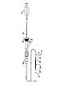
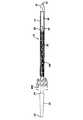
別の態様によれば、本発明は一定のセグメント化した自己拡張式ステントに対応する一定の配給システムに関連している。この一定のセグメント化した自己拡張式ステントに対応する配給システムは先端部および基端部を有する一定の細長い管状部材を含む一定の外側のシース、およびこの外側のシースの中に同軸に且つ摺動自在に配置されている一定の内側の軸部を含み、この内側の軸部は一定の先端部および一定の基端部を有しており、さらに、この軸部は上記セグメント化した自己拡張式のステントの少なくとも一部分を放出可能に固定するための係合部分を含む一定のカラーを有している。 According to another aspect, the invention relates to a delivery system that accommodates a segmented self-expanding stent. The delivery system corresponding to the segmented self-expanding stent includes an outer sheath including an elongated tubular member having a distal end and a proximal end, and coaxially and slides into the outer sheath. Including an inner shaft portion that is freely arranged, the inner shaft portion having a distal end portion and a proximal end portion; and the shaft portion is a segmented self-expanding type. And a collar including an engagement portion for releasably securing at least a portion of the stent.
種々のステント構造が多くの場合において種々の半径方向に拡張性の部材または架橋要素により接続されているフープにより構成されている。特定のステント設計において、上記の架橋要素は上記の半径方向に拡張性の部材における全ての先端部分またはループあるいはそれぞれのフープを一定の隣接している半径方向に拡張性の部材における一定の対応している先端部分またはループあるいはフープに接続できる。この種の設計は一定の比較的に低い柔軟性のステントを構成する。また、別のステント設計においては、上記架橋要素は全ての先端部分またはループの組を接続するのではなく、これらの架橋部は周期的に配置されている。これらの架橋部が周期的に離間している場合に、不連続状態の先端部分またはループの間に開口状態の隙間が存在するようになる。このような設計は柔軟性を高めることができるが、例えば、ステントのステント配備システム内への装填中またはステントの配備中において、そのステントが圧縮性の軸方向の負荷を受ける場合にそれぞれの不連続状態の先端部分またはループにおける潜在的な変形が生じる可能性がある。本発明のアンビル型架橋部の設計は上記のような先端部分またはループの間の一定の接続位置として作用することなく隣接している不連続状態の先端部分またはループの間における隙間を効果的に充填するために利用できる。従って、柔軟性の点において全く犠牲を生じない。 Different stent structures are often constructed with hoops connected by different radially expandable members or bridging elements. In a particular stent design, the bridging element corresponds to a constant in the radially expandable member that is adjacent to all the tips or loops or respective hoops in the radially expandable member. Can be connected to the tip or loop or hoop. This type of design constitutes a relatively low flexibility stent. Also, in other stent designs, the bridging elements do not connect all the tip portions or loop sets, but the bridging portions are arranged periodically. When these bridging portions are periodically separated, an open gap exists between the discontinuous tip portions or loops. Such a design can provide greater flexibility, however, for example, if the stent is subjected to a compressible axial load during loading or deployment of the stent into the stent deployment system. Potential deformation in the continuous tip or loop can occur. The anvil-type bridge design of the present invention effectively eliminates the gap between adjacent discontinuous tip portions or loops without acting as a constant connection position between the tip portions or loops as described above. Available for filling. Therefore, there is no sacrifice in terms of flexibility.
加えて、上記アンビル型架橋部の設計はそのステントの表面積を増加するために役立つ。さらに、このような増加した表面積は薬物配給のために利用可能な薬物の量を増加することにより一定の薬物放出特性を改善するために利用できる。本質的に、ステントにおける増加された表面積はその上におけるさらに多量の薬物の被覆を可能にする。 In addition, the anvil-type bridge design serves to increase the surface area of the stent. Further, such increased surface area can be used to improve certain drug release characteristics by increasing the amount of drug available for drug delivery. In essence, the increased surface area on the stent allows the coating of higher amounts of drug thereon.
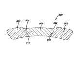
本発明の内腔内医療装置は一定の内腔内におけるこの装置の適当な位置決めを確実に行なうために高い放射線不透過性のマーカーを利用できる。これらのマーカーは上記装置自体に一体である一定のハウジングを含み、これにより、その装置の配備および操作の対する影響を確実に最少にできる。また、上記のハウジングは上記ステントの全体の外形に対する影響を最少にするように造形されている。例えば、一定の適当に造形されているハウジングは一定のステントが一定の6フレンチの配給システムの中に嵌合するために一定の7フレンチ(1フレンチ=1/3mm)の配給システムの中において利用される一定の放射線不透過性のステント・マーカーの寸法を維持することを可能にする。このマーカーはまた上記装置自体を形成している材料よりも一定の高い放射線不透過性を有する適当に寸法付けられているマーカー・インサートを含む。このマーカー・インサートは上記ハウジングの曲率に適合するように寸法付けられていて、一定の密接した無干渉性の適合を確実にしている。さらに、このマーカー・インサートは上記装置の材料に対してガルバニ・シリーズにおいて近い一定の材料により作成されていて、電蝕の影響を実質的に最少にするように寸法付けられている。 The intraluminal medical device of the present invention can utilize highly radiopaque markers to ensure proper positioning of the device within a lumen. These markers include a housing that is integral to the device itself, thereby ensuring minimal impact on the deployment and operation of the device. The housing is shaped to minimize the effect on the overall outer shape of the stent. For example, a properly shaped housing can be used in a 7 French (1 French = 1/3 mm) delivery system for a stent to fit into a 6 French delivery system. It is possible to maintain a certain radiopaque stent marker dimension. The marker also includes a suitably sized marker insert that has a certain higher radiopacity than the material forming the device itself. The marker insert is dimensioned to match the curvature of the housing to ensure a constant and incoherent fit. In addition, the marker insert is made of a constant material close to the device material in the galvanic series and is dimensioned to substantially minimize the effects of galvanic corrosion.
上記の本発明の改善された内腔内医療装置はX線透視下におけるこの装置の放射線不透過性を高めることにより一定の内腔内における比較的に正確な配置および処置後の可視化を行なう。上記のマーカー・ハウジングが装置と一体であるので、これらは一定の別の処理において取り付ける必要のあるマーカーよりも製造が簡単であり安価である。 The improved intraluminal medical device of the present invention described above provides relatively accurate placement and post-procedural visualization within a given lumen by increasing the radiopacity of the device under fluoroscopy. Because the marker housings described above are integral to the device, they are easier to manufacture and less expensive than markers that need to be installed in certain alternative processes.
上記の本発明の改善された放射線不透過性の内腔内医療装置は上記のマーカー・インサートが上記のマーカー・ハウジングの中に固定して位置決めされることを確実にする一定の方法を利用して製造されている。このマーカー・ハウジングは同一のチューブからレーザー切断されており上記装置と一体である。このようなレーザー切断処理の結果として、そのマーカー・ハウジング内における穴は半径方向において円錐形であり、その外表面部の直径はその内表面部の直径よりも大きい。このようなマーカー・ハウジングにおける円錐形状のテーパー部分の作用は上記装置が配置された後にそのマーカー・ハウジングが移動することを防ぐために上記マーカー・インサートとそのマーカー・ハウジングとの間における一定の締り嵌めを行なうことにおいて有利である。このマーカー・インサートはアニール処理したリボン素材から一定のディスク材をパンチ処理してこの材料を上記マーカー・ハウジングと同一の曲率半径を有するように造形することにより一定のけん縮状態の装置内に装填される。さらに、このディスク材が上記マーカー・ハウジングの中に装填されると、一定のコイニング処理が用いられてそのマーカーがハウジングの表面の下方に適当に支持される。このコイニング・パンチはまた上記マーカー・ハウジングと同一の曲率半径を維持するように造形されている。この結果、上記のコイニング処理はマーカー・ハウジングの材料を変形して一定の突出部分を形成し、これにより、上記のインサートまたはディスク材を内部に係止する。 The improved radiopaque intraluminal medical device of the present invention described above utilizes a method that ensures that the marker insert is fixedly positioned within the marker housing. Manufactured. The marker housing is laser cut from the same tube and is integral with the device. As a result of such a laser cutting process, the hole in the marker housing is conical in the radial direction and the outer surface diameter is larger than the inner surface diameter. The action of the conical tapered portion in such a marker housing is to provide a constant interference fit between the marker insert and the marker housing to prevent the marker housing from moving after the device is in place. Is advantageous in performing. This marker insert is loaded into a device in a certain crimped state by punching a certain disk material from annealed ribbon material and shaping this material to have the same radius of curvature as the marker housing. Is done. In addition, when the disc material is loaded into the marker housing, a coining process is used to properly support the marker below the surface of the housing. The coining punch is also shaped to maintain the same radius of curvature as the marker housing. As a result, the coining process deforms the material of the marker housing to form a constant protrusion, thereby locking the insert or disc material therein.
別の実施形態において、本発明の内腔内医療装置は多数の個々の独立している自己拡張式ステント・セグメントを備えており、これらのステント・セグメントは一定の配給シースの中に拘束されている時に相互連結して配備時に分離するように構成されている。これらの要素は独立しているので、望ましくない種々の力および/または負荷が全く伝達されない。 In another embodiment, the endoluminal medical device of the present invention comprises a number of individual independent self-expanding stent segments that are constrained within a delivery sheath. It is configured to be interconnected and separated during deployment. Because these elements are independent, no undesirable forces and / or loads are transmitted at all.
上記の独立型ステント構造の主な利点は一定の制御された様式で個々のセグメントを配備する能力である。さらに、上記の内部連結式の結合は一定の配備状態のセグメントが一定の脈管壁部に対してしっかりと対抗するまで一定の配備状態のセグメントをその配給システムから離脱させないように設計できる。このような手段が無ければ、それぞれの短い個々のセグメントがそれぞれの完全な直径まで拡張する際に一定の無制御状態の様式でその配給システムから進出する傾向が高くなる。 The main advantage of the above stand-alone stent structure is the ability to deploy individual segments in a controlled manner. In addition, the interconnected connection described above can be designed to prevent the deployed segment from leaving the delivery system until the deployed segment firmly opposes the vessel wall. Without such means, each short individual segment is more likely to advance from its distribution system in a constant uncontrolled manner as it expands to its full diameter.
本発明の別の利点は医者に標的の血管の病状に対する治療を調整するための柔軟性を賦与することを含む。具体的に言えば、支持骨格部分の長さを一定の病巣の長さに正確に適合することが可能になる。また、多数個の病巣を単一の配給装置を用いて単一の介入において治療することが可能になる。さらに、随意的に、治療部位に配備される個々のセグメントのピッチまたは間隔がその支持骨格部分の密度を増減するために変更可能になる。また、薬物溶出技法との組み合わせにおいて利用する場合に、本発明は脈管の単一の長さ当たりの薬物の投薬量を変更するために使用することも可能になる。 Another advantage of the present invention includes providing the physician with the flexibility to tailor treatment to the target vascular condition. Specifically, the length of the support skeleton can be accurately matched to a certain lesion length. It also allows multiple lesions to be treated in a single intervention using a single delivery device. Further, optionally, the pitch or spacing of individual segments deployed at the treatment site can be varied to increase or decrease the density of the support skeleton portion. Also, when utilized in combination with drug elution techniques, the present invention can also be used to alter the dosage of drug per single length of vessel.
上記の配給装置は一定範囲の場合に対応して予想される最大数の個々のセグメントにより予備装填される。従って、同一のシステムを一定の短い集中した病巣を治療するために使用することも可能であり、あるいは、一定の長い分散した病巣を治療するためにも使用できる。なお、一定の短い病巣の場合に、大部分の予備装填されたステント・セグメントは未使用になり、廃棄可能になると考えられる。 The delivery device is preloaded with the maximum number of individual segments expected for a range of cases. Thus, the same system can be used to treat certain short focused lesions, or it can be used to treat certain long dispersed lesions. It should be noted that in the case of certain short lesions, most of the preloaded stent segments are considered unused and can be discarded.
従来のステントは多くの場合においてその装置の周囲において周期的に隣接しているセグメントを連結している架橋部により接続されている拡張可能な構造の複数のセグメントにより構成されている。一方、上記のような不連続状態の独立している構造のセグメントによるシステムはその長手方向の伸び、圧縮または捩れに対して一定の無反応性を示す。本質的に、隣接している構造部材を接続するための架橋部が無ければ、これらの構造は脈管が伸びたり捩れたりする場合に引っ張られたり捩れたりしなくなる。また、このようなシステムは曲りに対しても一定の無反応性を示す。従って、上記の短い独立しているそれぞれのセグメントは容易に外形をたどり一定の曲がっている解剖学的構造に対して一致する。 Conventional stents are often composed of a plurality of segments of expandable structure connected by bridging connecting periodic adjacent segments around the device. On the other hand, a system with discrete structural segments as described above exhibits a certain unresponsiveness to its longitudinal elongation, compression or torsion. In essence, without a bridge to connect adjacent structural members, these structures will not be pulled or twisted when the vessel is stretched or twisted. Also, such a system shows a certain level of non-responsiveness to bending. Thus, each short independent segment described above easily conforms to a contoured anatomical structure.
従って、本発明によれば、従来に比して操作性および配備性において優れているステントが提供できる。 Therefore, according to the present invention, it is possible to provide a stent that is superior in operability and deployability as compared with the prior art.
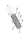
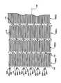
本発明はステントを含む多数の医療装置について、または、これらに関連して使用可能であるが、説明を簡単にするために、自己拡張式のニチノール・ステントに関連して本発明の一例の実施形態が以下において詳細に説明されている。図1および図2において、一定のステント100が示されており、このステント100は本発明と共に使用可能である。図1および図2はこの例示的なステント100をその未拡張状態または圧縮状態において示している。このステント100は好ましくはニチノール等のような一定の超弾性の合金により作成されている。最も好ましくは、このステント100は約50.0パーセント(%)(本明細書において用いられているように、これらのパーセント値は重量パーセント値を意味する)のニッケル(Ni)乃至約60%のNi、さらに好ましくは約55.8%のNiを含有していて、残りの部分がチタン(Ti)である一定の合金により作成されている。好ましくは、上記ステント100は体温において超弾性になるように設計されており、約24℃乃至約37℃の範囲内の一定のAf温度を有していることが好ましい。このようなステント100の超弾性の設計により、このステント100はつぶれの回復性を有するようになり、上述したように、異なる適用例における多数の脈管装置に対応する一定のステントまたはフレームとして有用になる。 Although the present invention can be used with or in connection with a number of medical devices including stents, for ease of explanation, an example implementation of the present invention in connection with a self-expanding Nitinol stent is described. The form is described in detail below. 1 and 2, a
上記ステント100は前方および後方の開口端部102および104、およびこれらの間に延在している一定の長手軸106を有する一定の管状の部材である。この管状部材は図1および図2におけるような、一定の患者の体内に挿入して種々の脈管の中を通過するための、第1の比較的に小さい直径、および図3および図4におけるような、一定の脈管の標的領域内に配備するための、第2の比較的に大きな直径を有する。さらに、この管状部材は複数の隣接しているループ108により作成されており、図1は前方および後方の端部102および104の間に延在している各フープ108(a)乃至108(d)を示している。さらに、これらのフープ108は複数の長手方向に沿う支柱部110およびこれらの隣接している支柱部を接続している複数のループ112を含み、それぞれの隣接している支柱部はそれぞれの対向している端部において接続していて一定の実質的にS字またはZ字の形状のパタンを形成している。一方、各ループ112は湾曲していて、実質的に半円形状であり、それぞれの中心部分114において対称形の部分を有している。 The
上記ステント100はさらに複数の架橋部116を含み、これらの架橋部116は隣接している各フープ108を接続しており、図5を参照することにより最良に説明することができる。すなわち、各架橋部116は2個の端部118および120を有している。さらに、これらの架橋部116は1個の支柱部および/またはループに取り付けられている1個の端部、および一定の隣接しているループにおける一定の支柱部および/またはループに取り付けられている別の端部を有している。さらに、これらの架橋部116は隣接している各支柱部をそれぞれのループ接続点122および124に対応する架橋位置において一体に接続している。例えば、架橋端部118はループ接続点122に対応する架橋位置においてループ114(a)に接続しており、架橋端部120はループ接続点124に対応する架橋位置においてループ114(b)に接続している。さらに、それぞれのループ接続点に対応する架橋位置は一定の中心部分126を有している。さらに、これらのループ接続点に対応する架橋位置は上記長手軸に対して一定の角度を成して分離している。すなわち、それぞれの接続点は互いに直接的に対向していない。本質的に、上記ステントの長手軸に対して平行になるような一定の直線をこれらの接続点の間に画くことはできない。 The
上記の幾何学的な形状は上記ステントの全体に歪を分配することに役立ち、ステントの屈曲時に金属対金属の接触を防ぎ、各支柱部、ループおよび架橋部の間の開口している大きさを最小にする。これらの支柱部、ループおよび架橋部の数の設計の性質は上記ステントの動作特性および疲労寿命特性を決定する場合に重要な因子である。すなわち、このステントの合成を改善するためにはこれらの支柱部を大きくする必要があり、それゆえ、フープ1個当たりの支柱部の数を減らす必要があることが既に分かっている。しかしながら、比較的に小形の支柱部および比較的に多数の支柱部を有するステントがそのステントの構成を実際に改善して比較的に大きな剛性を賦与することも現在において見出されている。好ましくは、それぞれのフープは24個乃至36個あるいはそれ以上の支柱部を有している。また、400を超える支柱部の長さL(インチ単位)に対するフープ1個当たりの支柱部の数の比率値を有する一定のステントが一般的に200よりも小さい一定の比率値を有する従来技術の種々のステントに優る高められた剛性を有することが確定している。なお、一定の支柱部の長さは図1において示されているようなステント100の長手軸106に対して平行にその圧縮された状態において測定されている。 The geometric shape helps distribute the strain throughout the stent, prevents metal-to-metal contact when the stent is bent, and the size of the opening between each strut, loop and bridge. To minimize. The design nature of the number of these struts, loops and bridges is an important factor in determining the operational and fatigue life characteristics of the stent. That is, it has already been found that in order to improve the synthesis of the stent, these struts need to be enlarged and therefore the number of struts per hoop needs to be reduced. However, it has now been found that a stent having a relatively small strut and a relatively large number of struts actually improves the stent configuration and provides a relatively large stiffness. Preferably, each hoop has 24 to 36 or more struts. Also, certain stents having a ratio value of the number of struts per hoop to a strut length L (in inches) of over 400 typically have a constant ratio value less than 200. It has been determined to have increased stiffness over various stents. Note that the length of the fixed struts is measured in its compressed state parallel to the
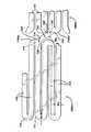
図2および図3の比較により分かるように、上記ステント100の幾何学的形状はこのステント100がその未拡張状態からその拡張状態に配備される時に極めて大きく変化する。一定のステントが直径方向の変化を生じる時に、それぞれのループおよび架橋部の中における支柱部の角度および歪のレベルが影響を受ける。この場合に、全てのステントの特徴部分がこのステントの信頼性が高まりその強度が均一になるように一定の予測可能な様式で歪むことが好ましい。加えて、ニチノールの特性が応力よりも歪により全体的に制限されるので、それぞれの支柱部、ループおよび架橋部が受ける最大の歪を最小にすることが好ましい。以下においてさらに詳細に論じられているように、上記ステントは図10および図11において示されているようにその未拡張状態において一定の配給システムの中に支持されている。その後、このステントが配備される時に、このステントは図3において示されているようなその拡張状態に向かって拡張することが可能になり、好ましくは、その標的の脈管における直径と同一であるかこれよりも大きい一定の直径を有する。さらに、ワイヤにより作成されている種々のニチノール・ステントは、レーザー切断によるステントに比して、ほとんど同一の様式で展開し、同一設計の拘束に依存している。また、種々のステンレス・スチール製のステントも種々のバルーンまたは別の装置からの力により補助される場合に幾何学的形状の変化の点において同様に展開する。 As can be seen from a comparison of FIGS. 2 and 3, the geometry of the
上記ステントの各特徴部分が受ける最大の歪を最小にする試みにおいて、本発明は歪を他の領域よりも破損し難いステントのそれぞれの領域に分配する構造的な幾何学的形状を利用している。例えば、ステントにおける一例の最も損傷しやすい領域は接続している各ループの内側の半径部分である。すなわち、これらの接続しているループはステントの全ての特徴部分における最大の変形を受ける。さらに、このループの内側の半径部分は通常においてそのステントにおける歪の最大の量を有する領域になると考えられる。この領域はそのステントにおける通常的に最小の半径部分である点においても重要である。すなわち、応力の集中は可能な限りに最大の半径を維持することにより全体的に制御または最小化される。同様に、本発明者は架橋部および架橋部の各接続点における局所的な歪の集中を最少にすることを望んでいる。このことを達成するための一例の方法は加えられる力に相当する各特徴部分の幅を維持しながら可能な限り最大の半径を利用することである。また、別の考慮点はステントにおける最大の開口面積を最小にすることである。加えて、ステントを切り出す元のチューブの効率的な利用により、そのステントの強度および塞栓性の物質を捕捉する能力を増大できる。 In an attempt to minimize the maximum strain experienced by each feature of the stent, the present invention utilizes a structural geometry that distributes the strain to each region of the stent that is less likely to break than other regions. Yes. For example, an example of the most vulnerable area in a stent is the inner radius of each connected loop. That is, these connecting loops undergo maximum deformation in all features of the stent. In addition, the inner radius of this loop is usually considered to be the region with the greatest amount of strain in the stent. This region is also important in that it is usually the smallest radius on the stent. That is, stress concentration is globally controlled or minimized by maintaining the maximum radius possible. Similarly, the present inventor wants to minimize local strain concentration at the bridge and at each connection point of the bridge. An example method for accomplishing this is to utilize the largest possible radius while maintaining the width of each feature corresponding to the applied force. Another consideration is to minimize the maximum open area in the stent. In addition, efficient utilization of the original tube from which the stent is cut can increase the strength of the stent and its ability to capture embolic material.
上記設計の目的の多くは図1,2および5において示されている本発明の一定の例示的な実施形態により達成されている。これらの図から分かるように、ループと架橋部との各接続点において最大の半径を維持する最も簡潔な設計は支柱部を接続しているループの中心線に対して非対称である。すなわち、それぞれのループと架橋部の接続点の中心126はこれらが取り付けられている各ループ112の中心114からずれている。この特徴はステントに大きな弾性歪が必要とされる極端な屈曲の必要条件を有することを求める大きな拡張の比率を有するステントにおいて特に有利である。この場合に、ニチノールは極めて多量の弾性歪による変形に耐えることができ、それゆえ、上記の特徴はこの合金により作成されている種々のステントに十分に適合する。この結果、この特徴はNi−Ti型またはその他の材料の特性を最大に利用して半径方向の強度を高めること、ステント強度の均一性を改善すること、局所的な歪の量を最少にすることにより疲労寿命を改善すること、塞栓性の物質の捕捉を促進する比較的に小さな開口領域を可能にすること、および不規則な脈管壁部の形状および湾曲部分におけるステントの並置性を改善することを可能にする。 Many of the above design objectives have been achieved by certain exemplary embodiments of the present invention shown in FIGS. As can be seen from these figures, the simplest design that maintains the maximum radius at each connection point between the loop and the bridge is asymmetric with respect to the centerline of the loop connecting the struts. That is, the
図5において示されているように、ステント100は軸106に対して平行に中心部分114において測定した場合の一定の幅W1を有する各ループ112を接続している支柱部を有しており、この幅W1は軸106自体に対して垂直に測定した場合の支柱部の幅W2よりも大きい。実際に、各ループの厚さはこれらのループがそれぞれの中心部分の近くにおいて最も厚くなるように変化していることが好ましい。すなわち、このことは支柱部における歪による変形を増大すると共に各ループの極限半径における最大歪の量を減少する。さらに、このことはステントの破損の危険性を減少して、ステントがその半径強度特性を最大にすることを可能にする。この特徴はステントに大きな弾性歪が必要とされる極端な屈曲の必要条件を有することを求める大きな拡張の比率を有するステントにおいて特に有利である。この場合に、ニチノールは極めて多量の弾性歪による変形に耐えることができ、それゆえ、上記の特徴はこの合金により作成されている種々のステントに十分に適合する。この結果、この特徴はNi−Ti型またはその他の材料の特性を最大に利用して半径方向の強度を高めること、ステント強度の均一性を改善すること、局所的な歪の量を最少にすることにより疲労寿命を改善すること、塞栓性の物質の捕捉を促進する比較的に小さな開口領域を可能にすること、および不規則な脈管壁部の形状および湾曲部分におけるステントの並置性を改善することを可能にする。 As shown in FIG. 5, the
上述したように、一定のステントがその圧縮状態からその拡張状態まで展開するかその逆に変形する時に架橋部の幾何学的形状が変化する。すなわち、一定のステントが直径方向に変化すると、支柱部の角度およびループの歪が影響を受ける。さらに、各架橋部はループまたは支柱部のいずれか、またはこれらの両方に接続しているので、これらもまた影響を受ける。この場合に、ステントがそのステント配給システムの中に装填されている間におけるそのステントの一端部の他端部に対する捩れは避ける必要がある。すなわち、架橋部の両端部に配給される局所的なトルクはその架橋部の幾何学的形状をずらす。このような架橋部の設計がそのステントの周囲において繰り返されている場合には、上記のずれがその架橋部により接続されている2個のループの回転方向のずれを生じる。さらに、本発明におけるように、架橋部の設計がステント全体において繰り返されていれば、このずれはそのステントの長さに沿って生じることになる。この現象は配備時おける他端部に対する一端部の回転を考慮した場合に一定の累積的な作用と言える。以下において説明されているような一定のステント配給システムは先端部を最初に配備した後に、基端部が拡張することを可能にしている。この場合に、ステントの回転を固定した状態で保持しながら脈管壁部の中にその先端部を固定した後に、その基端部を放出することは望ましくないと考えられる。すなわち、このことはステントが脈管の中に少なくとも部分的に配備された後に平衡状態になるまでそのステントが捩れるか巻いて回転する可能性がある。さらに、このような回転の作用は脈管に対する損傷を生じる可能性がある。 As described above, the bridge geometry changes when a stent expands from its compressed state to its expanded state, or vice versa. That is, when a certain stent changes in diameter, the strut angle and loop distortion are affected. Furthermore, since each bridge is connected to either the loop or the strut or both, they are also affected. In this case, it is necessary to avoid twisting the other end of the stent while the stent is being loaded into the stent delivery system. That is, the local torque distributed to both ends of the bridging portion shifts the geometric shape of the bridging portion. If such a bridge design is repeated around the stent, the above deviation will cause a shift in the rotational direction of the two loops connected by the bridge. Furthermore, if the bridge design is repeated throughout the stent, as in the present invention, this deviation will occur along the length of the stent. This phenomenon can be said to be a certain cumulative effect when considering the rotation of one end relative to the other end during deployment. Certain stent delivery systems, as described below, allow the proximal end to expand after the initial deployment of the distal end. In this case, it may not be desirable to release the proximal end after fixing the distal end in the vessel wall while holding the rotation of the stent fixed. That is, this can cause the stent to twist or roll until it is in equilibrium after it is at least partially deployed in the vessel. Furthermore, such rotational effects can cause damage to the vessels.
しかしながら、図1および図2において示されているような本発明の一例の実施形態はステントの配備時において生じる上記のような事態の可能性を減少している。すなわち、架橋部の幾何学的形状をステントの長手方向に沿って鏡像化することにより、それぞれのZ字形の部分またはS字形の部分における回転方向のずれを交互にすることができ、配備中または拘束中の一定のステントにおける任意の2点の間の大きな回転方向の変化が最小になる。すなわち、ループ108(b)をループ108(c)に接続している各架橋部116は左から右に上方に角度付けされているが、ループ108(c)をループ108(d)に接続している各架橋部は左から右に下方に角度付けされている。さらに、この交互のパタンがステント100の長さに沿って繰り返されている。従って、これらの架橋部の傾斜の交互のパタンはそのステントの捩れ特性を改善して、任意の2個のフープにおけるステントのあらゆる捩れまたは回転を最小にする。さらに、このような交互の架橋部の傾斜はステントが生体内において捩れ始めた場合に特に有利である。すなわち、ステントが捩れると、そのステントの直径が変化する。この場合に、交互の架橋部の傾斜はこの作用を最小にする。一方、全てが同一方向に傾斜している架橋部を有する一定のステントの直径は一方向に捩れる場合に拡張する傾向があり、別の方向に捩れる場合に縮小する傾向がある。すなわち、交互の架橋部の傾斜により、この作用を最小にして局在化することができる。 However, the exemplary embodiment of the present invention as shown in FIGS. 1 and 2 reduces the likelihood of such a situation that occurs during stent deployment. That is, by mirroring the geometry of the bridge along the longitudinal direction of the stent, rotational shifts in each Z-shaped or S-shaped portion can be alternated during deployment or Large rotational changes between any two points on a restrained constant stent are minimized. That is, each bridging
好ましくは、一定のステントは小さな直径のチューブ材からレーザー切断されている。従来技術のステントの場合に、この製造方法がそれぞれ軸方向の幅W2,W1およびW3を有する支柱部、ループおよび架橋部等のような幾何学的な特徴部分を伴う設計を達成しており、これらの幅はチューブ材の壁部の厚さT(図3において示されている)よりも大きい。ステントが圧縮している時に、その屈曲の大部分がそのステントを長手方向にそって切断してこれを平坦にした場合に得られる平面内において生じている。しかしながら、それぞれの厚さよりも大きな幅を有している、個々の架橋部、ループおよび支柱部においては、平面外における屈曲に対する抵抗よりも大きな平面内における屈曲に対する抵抗が生じる。この理由により、これらの架橋部および支柱部が捩れやすくなり、ステントが全体としてさらに容易に屈曲する。さらに、この捩れは一定の曲りの状況であり、この状況は予測不能であり潜在的に高い歪を生じる可能性がある。 Preferably, certain stents are laser cut from small diameter tubing. In the case of prior art stents, this manufacturing method achieves a design with geometric features such as struts, loops and bridges having axial widths W2, W1 and W3, respectively. These widths are larger than the wall thickness T (shown in FIG. 3) of the tube material. As the stent is compressed, the majority of its bending occurs in the plane obtained when the stent is cut along its length to flatten it. However, in individual bridging sections, loops and struts having a width greater than their respective thickness, resistance to bending in the plane is greater than resistance to bending out of plane. For this reason, these bridging portions and strut portions are easily twisted, and the stent is bent more easily as a whole. Furthermore, this twist is a constant bend situation, which is unpredictable and can potentially cause high strain.
しかしながら、上記の問題は図1乃至図5において示されているような本発明の例示的な実施形態において解消されている。これらの図から分かるように、それぞれの支柱部、フープおよび架橋部の幅はそのチューブ材の壁部の厚さと同等であるかこれよりも小さい。従って、全ての屈曲、それゆえ、全ての歪が「平面外(out-of-plane)」において生じる。このことはステントの捩れを最小にして、その曲りおよび予測不能な歪の状況を最少にするか排除する。この特徴はステントに大きな弾性歪が必要とされる極端な屈曲の必要条件を有することを求める大きな拡張の比率を有するステントにおいて特に有利である。この場合に、ニチノールは極めて多量の弾性歪による変形に耐えることができ、それゆえ、上記の特徴はこの合金により作成されている種々のステントに十分に適合する。この結果、この特徴はNi−Ti型またはその他の材料の特性を最大に利用して半径方向の強度を高めること、ステント強度の均一性を改善すること、局所的な歪の量を最少にすることにより疲労寿命を改善すること、塞栓性の物質の捕捉を促進する比較的に小さな開口領域を可能にすること、および不規則な脈管壁部の形状および湾曲部分におけるステントの並置性を改善することを可能にする。 However, the above problem has been overcome in an exemplary embodiment of the invention as shown in FIGS. As can be seen from these figures, the width of each column part, hoop and bridge part is equal to or smaller than the thickness of the wall part of the tube material. Thus, all bends, and hence all distortions, occur “out-of-plane”. This minimizes the twisting of the stent and minimizes or eliminates its bending and unpredictable strain situations. This feature is particularly advantageous in stents having large expansion ratios that require the stent to have extreme bending requirements where large elastic strain is required. In this case, Nitinol can withstand deformation due to a very large amount of elastic strain, and thus the above features are well suited to various stents made with this alloy. As a result, this feature maximizes the properties of Ni-Ti type or other materials to increase radial strength, improve stent strength uniformity, and minimize the amount of local strain. Improved fatigue life, enables a relatively small opening area to facilitate the capture of embolic material, and improves stent apposition in irregular vessel wall shapes and bends Make it possible to do.
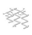
本発明と共に利用可能である一定のステントの別の例示的な実施形態が図6において示されている。図6は図1乃至図5において示されているステント100に類似しているステント200を示している。このステント200は複数の隣接しているフープ202により作成されており、図6はフープ202(a)乃至202(d)を示している。これらのフープ202はそれぞれ複数の長手方向に沿う支柱部204およびそれぞれの隣接している支柱部を接続している複数のループ206を含み、この場合に、それぞれの隣接している支柱部がその対向している端部において接続されていて一定の実質的にS字またはZ字の形状のパタンを形成している。このステント200はさらにそれぞれの隣接しているフープ202を接続している複数の架橋部208を含む。この図から分かるように、それぞれの架橋部208はそれぞれの隣接しているフープの間において非線形であり湾曲している。このような湾曲している架橋部を有することにより、それぞれの架橋部がそれぞれのループおよび支柱部の周囲において湾曲することが可能になり、これにより、それぞれのフープが互いにさらに近く配置できるようになり、このことはさらにこのステントの最大の開口面積を最小にしてその半径方向の強度を最大にしている。このことは図4を参照することにより最良に説明できる。上記のステントの幾何学的形状はそのステントの拡張時におけるそれぞれの架橋部、ループおよび支柱部の間に描くことのできる最大の円を最小にすることを目的としている。このような理論的な円の大きさを最小にすることはそのステントを大きく改善し、この理由は、このようなステントが患者の体内に挿入された後にその脈管を支持して塞栓性の物質を捕捉するための安定した支持骨格による支持を行なうことにさらに良好に適するからである。 Another exemplary embodiment of a stent that can be utilized with the present invention is shown in FIG. FIG. 6 shows a
上述したように、本発明のステントは一定の超弾性合金により作成されていることが好ましく、50.5原子百分率よりも多いニッケルおよびその残りとしてチタンを含有する一定の合金により作成されていることがさらに好ましい。このように50.5原子百分率を超えることはそのマルテンサイト相がオーステナイト相に完全に転移する温度(Af温度)が人間の体温よりも低く、好ましくは約24℃乃至約37℃であり、そのオーステナイト相が体温において唯一の安定な相である一定の合金を可能にする。 As mentioned above, the stent of the present invention is preferably made of a superelastic alloy, preferably made of a nickel-containing alloy with more than 50.5 atomic percent and titanium as its remainder. Is more preferable. Thus, exceeding 50.5 atomic percent means that the temperature at which the martensite phase completely transitions to the austenite phase (Af temperature) is lower than the human body temperature, preferably about 24 ° C. to about 37 ° C., The austenite phase allows for certain alloys where it is the only stable phase at body temperature.
ニチノール・ステントの製造において、この材料は最初に一定のチューブの形態である。このニチノールのチューブ材はカリホルニア州フレモントのニチノール・デバイスイズ・アンド・コンポーネンツ社(Nitinol Devices and Components)を含む多数の供給元から市場において入手可能である。その後、この管状の部材は一定の装置の中に装填されて、上述されていて各図面において示されているような、ステントの所定のパタンがこのチューブに切り込まれる。このような種々のステントまたはこれに類似の装置を作成するために種々の管状の装置にパタンを切り込むための装置は当該技術分野における通常の熟練者において周知であり市場において入手可能である。また、これらの装置は一般的に一定の切断用のレーザーが好ましくはマイクロプロセッサによる制御下において上記のパタンを切断している間に上記のチューブ材をその両方の開口端部の間において保持している。これらのパタンの寸法および様式、レーザーの位置決めの必要条件、およびその他の情報は一定のマイクロプロセッサの中にプログラムされていて、このマイクロプロセッサがその処理の全ての態様を制御する。上記ステントのパタンを切り出した後に、このステントは当該技術分野における熟練者において周知の多数の方法またはこれらの方法の組み合わせにより処理されて研磨される。その後、このステントはこのステントが完全にマルテンサイト相になり、その未拡張状態の直径に収縮するまで冷却されてから、その配給装置のシースの中に装填される。 In the manufacture of Nitinol stents, this material is initially in the form of a tube. This Nitinol tubing is commercially available from a number of sources including Nitinol Devices and Components of Fremont, California. The tubular member is then loaded into a device and a predetermined pattern of the stent, as described above and shown in the figures, is cut into the tube. Devices for cutting patterns in various tubular devices to make such various stents or similar devices are well known to those skilled in the art and are commercially available. These devices also generally hold the tubing between both open ends while a cutting laser is cutting the pattern, preferably under the control of a microprocessor. ing. The size and style of these patterns, laser positioning requirements, and other information are programmed into a microprocessor, which controls all aspects of the process. After cutting out the stent pattern, the stent is processed and polished by a number of methods or combinations of methods well known to those skilled in the art. The stent is then cooled until the stent is fully martensitic and contracts to its unexpanded diameter before being loaded into the delivery device sheath.
図15はニチノールにより形成されている一定の自己拡張式のステント1500の代替的で例示的な実施形態を示している。この例示的な実施形態において、複数の分割型の架橋部が架橋されていない各ループの間における一定の構造的な接続部分として作用することなくこれらのループの間における隙間を充填するために利用されている。本明細書において説明されているような、周期的に配置されている架橋部を特徴とする種々のステント設計において、その結果として生じる接続していないそれぞれのループの間の隙間は、特に、そのステントの一定のステント配給システム内への装填中およびその後のステント配給システムからの配備中において、不都合になる可能性がある。これらの装填および配備の状況の両方において、ステントは一定の小さな直径に拘束されて高い圧縮性の軸方向の力を受ける。さらに、これらの力は接続しているそれぞれの架橋部によりそのステントの中に軸方向に伝達されて、それぞれのループが架橋部により接続されていない領域内の隣接している各フープの望ましくない曲がりまたは圧縮を生じる可能性がある。一定の分割型架橋部は拘束された軸方向の圧縮の状況下における上記のような望ましくない変形を実質的に最小にするために利用できる。本質的に、分割型架橋部を有する一定のステントが拘束されて軸方向の圧縮を受けると、その分割型架橋部における隣接している端部の幅広の平坦な表面部分が、以下において詳述されているように、速やかに接触してそのステント構造の望ましくない変形を生じることなくその圧縮性の軸方向の負荷を伝達する。このような分割型架橋部の設計はステントの配備後において標準的な架橋部により生じる柔軟性の損失を伴うことなくステントの装填中および配備中における圧縮性の軸方向の負荷の伝達を可能にする点において特に有利である。 FIG. 15 illustrates an alternative exemplary embodiment of a self-expanding
上記分割型架橋部を含む一定のステントの有用性を説明するために一定の単純な例が利用できる。一般的に120度づつ離間している3個の架橋部を含む一定の拘束状態のステントはこれら3種類の架橋部を通してステントの装填および配備に伴う全体の圧縮性の負荷を伝達する必要がある。この場合に、その120度の円弧または間隔の中において接続していない各ループは不所望に変形して、潜在的にその面から外れる可能性があり、これにより、その全体のステント構造の圧縮が生じて潜在的にその装填または配備の特性に悪影響を及ぼす可能性がある。しかしながら、3個の標準的な架橋部および3個の分割型架橋部を有する一定のステントはその軸方向の圧縮性の負荷をさらに良く分配すると考えられ、その負荷の半分が、この場合に60度づつ離間している、それぞれの架橋部に加えられる。この結果、その60度の円弧または間隔の中に存在する接続していないループの数がさらに少なくなり、これらのループはその構造が圧縮性の軸方向の負荷を受ける時に不所望に変形する傾向が少なくなると考えられる。本質的に、圧縮性の軸方向の負荷の効率的な伝達を可能にすることにより、その分割型架橋部は拘束状態のステントにおける望ましくない圧縮または変形を防ぎ、あるいは、このような圧縮または変形により生じる可能性のある装填または配備の困難さを防ぐために役立つ。このことはこれ以外の場合には実用的でなくなると考えられる種々のステント設計における装填および配給を容易にする可能性がある。 Certain simple examples can be used to illustrate the usefulness of certain stents that include the above split bridges. A constrained stent that typically includes three bridges that are spaced 120 degrees apart must transmit the overall compressive load associated with stent loading and deployment through these three bridges. . In this case, each loop that is not connected within its 120 degree arc or spacing can undesirably deform and potentially dislodge from its face, thereby compressing its entire stent structure. Can potentially adversely affect its loading or deployment characteristics. However, certain stents with three standard bridges and three split bridges are believed to better distribute their axial compressive load, with half of that load being 60 in this case. Added to each bridging section, spaced apart by degrees. This results in a further reduction in the number of disconnected loops present in the 60 degree arc or spacing, and these loops tend to deform undesirably when the structure is subjected to a compressible axial load. Is expected to decrease. In essence, by allowing efficient transmission of compressible axial loads, the split bridge prevents unwanted compression or deformation in the constrained stent, or such compression or deformation. To help prevent loading or deployment difficulties that may arise. This can facilitate loading and delivery in various stent designs that would otherwise be impractical.
なお、各架橋部の対称形の装填および対称形の配置は好ましいが必ずしも必要ではないことに注意することが重要である。 It is important to note that symmetrical loading and symmetrical placement of each bridge is preferred but not necessary.
上記の分割型架橋部の設計は多数のステント設計において利用可能であるが、説明を容易にするために、この分割型架橋部の設計は図15において示されている例示的なステントに関連して説明されている。図示のように、このステント1500は複数の隣接しているフープ1502を含む。さらに、これらのフープ1502は複数の長手方向に沿う支柱部1504および隣接しているそれぞれの支柱部を接続している複数のループ1506を含み、この場合に、これらの隣接している支柱部1504はそれぞれの対向している端部において接続していて一定のS字またはZ字の形状のパタンを形成している。各ループ1506は湾曲状であり、それぞれの中心部分1508に対して対称形の部分を伴う実質的に半円形である。上記ステント1500はさらに隣接しているそれぞれのフープ1502を接続している複数の架橋部1510を含む。これらの架橋部1510は図5において示されていて上記において説明されている架橋部と同等である。すなわち、上記において説明されているように、この架橋部の配向はフープごとに変化していて、ステントの配備中または拘束中における一定のステントの任意の2点の間における回転方向の変化を最小にしている。さらに、上述したように、これらの支柱部、ループおよび架橋部の数および設計の性質はそのステントの動作特性および疲労寿命特性を決定する場合に重要な因子である。 Although the split bridge design described above can be used in many stent designs, for ease of explanation, this split bridge design is associated with the exemplary stent shown in FIG. Explained. As shown, the
上記ステント1500はまた複数の分割型架橋部1512も含む。この分割型架橋部1512は任意の適当な構成を含むことができ、上記架橋部1510の間において任意の適当なパタンで配置できる。図15において示されている例示的な実施形態において、これらの分割型架橋部1512は各架橋部1510の配向と反対の一定の方向に配向されていて、それぞれの架橋部1510および分割型架橋部1512の一定の対称形の構成が形成されている。なお、上述したように、このような対称形の構成は必ずしも必要ではないが、好ましいと考えられる。上記架橋部1510の設計とは異なり、分割型架橋部1512はこの分割型架橋部1512の隣接している各部分の間において接触するための表面積を最大にするように設計されている。このような分割型架橋部の設計はその隣接している各部分の接触を可能にすることにより、隣接しているフープ1502が幾分不整合状態になる場合に力を伝達することができる。これらの分割型架橋部1512の幅または太さは好ましくは標準的な架橋部1510の幅または太さよりも大きく、当接式の接触のための付加的な表面積を与えている。さらに、各架橋部1510と同様に、それぞれの分割型架橋部1512は1個のループ1506に取り付けられている一方の独立している部分における一端部および一定の隣接しているフープ1502における一定のループ1506に取り付けられている一方の独立している部分における別の端部を有している。本質的に、それぞれの分割型架橋部1512は第1および第2の独立している部分を含み、これらはステント1500が圧縮性の軸方向の負荷を受けている場合に接触して、ステント1500が配備されている時には接触しない。 The
上記の分割型架橋部は標準的な架橋部により占有され得ない種々の隙間を充たす目的を果たす多数の形態を採ることができる。加えて、上記分割型架橋部の数および配列は事実上無制限である。 The above-described split-type cross-linking portion can take many forms that serve the purpose of filling various gaps that cannot be occupied by standard cross-linking portions. In addition, the number and arrangement of the split bridges is virtually unlimited.
上記の性質により、上記分割型架橋部はそれぞれの分割型架橋部における上記の各部分が少なくとも部分的に当接するので拘束状態の時に圧縮性の負荷の伝達を好都合に可能にする。しかしながら、従来の架橋部とは異なり、拡張状態の構造体が延伸、圧縮または屈曲する時にその張力または圧縮性の歪を伝達しない。すなわち、図16において示されているように、分割型架橋部はその構造体の拡張後において整合していない。従って、この分割型架橋部は外形の保全性および疲労の耐久性において従来の架橋部よりも有利であることが立証できる。 By virtue of the above properties, the split-type bridges advantageously allow the transmission of compressive loads when constrained, since the respective parts of the respective split-type bridges at least partially abut. However, unlike conventional bridging portions, the expanded structure does not transmit its tension or compressive strain when stretched, compressed or bent. That is, as shown in FIG. 16, the split-type bridging portions are not aligned after the structure is expanded. Therefore, it can be proved that this divided type cross-linking portion is more advantageous than the conventional cross-linking portion in the maintenance of the outer shape and the durability of fatigue.
種々の薬物、薬剤または配合物が種々のステント等のような医療装置を介して局所的に配給できる。例えば、ラパマイシンおよび/またはヘパリンが再狭窄、炎症および凝固を減少するために一定のステントにより配給できる。これらのステントにおける一例の可能性のある制限性の要因は種々の薬物、薬剤および/または配合物に対応してステントにおいて利用可能な表面積である。従って、上記の利点に加えて、上記分割型架橋部は種々の薬物、薬剤および/または配合物を固定できる付加的な表面積を提供している。 Different drugs, agents or compounds can be delivered locally via different medical devices such as different stents. For example, rapamycin and / or heparin can be delivered by certain stents to reduce restenosis, inflammation and coagulation. One possible limiting factor in these stents is the surface area available on the stent for various drugs, agents and / or formulations. Thus, in addition to the advantages described above, the split bridge provides additional surface area that can immobilize various drugs, agents and / or formulations.
本特許出願の前の部分において述べられているように、上記超弾性の合金の放射線不透過性よりも高い放射線不透過性を有する種々のマーカーが上記ステントの脈管内における比較的に正確な配置を容易にするために利用できる。加えて、種々のマーカーがステントが完全に配備された時およびその如何を決定するために利用できる。例えば、これらのマーカーの間の間隔を決定することにより、その配備状態のステントがその最大の直径を達成しているか、あるいは、一定の粘着処理により追随して調節されているかを決定することができる。図7はそれぞれの端部に少なくとも1個のマーカーを有している図1乃至図5において示されているステント100の一定の例示的な実施形態を示している。一定の好ましい実施形態において、フープ1個当たりに36個の支柱部を有する一定のステントが6個のマーカー800に適合可能である。それぞれのマーカー800は一定のマーカー・ハウジング802および一定のマーカー・インサート804を含む。さらに、このマーカー・インサート804はX線透視下において一定の高い放射線不透過性を有する任意の適当な生体適合性の材料により形成できる。換言すれば、これらのマーカー・インサート804はステント100を構成している材料の放射線不透過性よりも高い一定の放射線不透過性を有していることが当然に好ましい。また、上記マーカー・ハウジング802のステントに対する付加はそのステントの端部における疲労寿命を伸ばすためにそのステント100のそれぞれの端部における最後の2個のフープにおける各支柱部の長さをそのステントの本体部分における支柱部の長さよりも大きくすることを必要とする。これらのマーカー・ハウジング802は好ましくは上記において簡単に説明されているようなステントと同一のチューブにより切り出されている。従って、これらのハウジング802はステント100に一体である。このように、これらのハウジング802をステント100と一体にすることはそれぞれのマーカー800がそのステントの動作に影響を及ぼさないことを確実にするために役立つ。 As stated in the previous part of this patent application, various markers having radiopacity higher than that of the superelastic alloy are relatively accurately positioned within the stent vessel. Available to facilitate. In addition, various markers are available to determine when and how the stent is fully deployed. For example, by determining the spacing between these markers, it can be determined whether the deployed stent has achieved its maximum diameter, or is being adjusted following a certain sticking process. it can. FIG. 7 shows an exemplary embodiment of the
図8は一定のマーカー・ハウジング802の断面図である。このハウジング802は図7において示されているように外表面部から見た場合に楕円形であると言える。レーザー切断処理の結果として、マーカー・ハウジング802における穴806は半径方向において円錐形であり、図8において示されているように、外表面部808は内表面部810の直径よりも大きな直径を有している。このマーカー・ハウジング802における円錐形のテーパー部分はマーカー・インサート804とマーカー・ハウジング802との間に締り嵌めを行なってステント100を配備した後にマーカー・インサート804が移動することを防ぐことに役立つ。以下に、このマーカー・インサート804をマーカー・ハウジング802に係止する方法が詳細に説明されている。 FIG. 8 is a cross-sectional view of a
上述したように、マーカー・インサート804は上記のステントまたはその他の医療装置を形成している超弾性材料よりも高い一定の放射線不透過性を有する任意の適当な材料により作成できる。例えば、このマーカー・インサート804はニオビウム、タングステン、金、プラチナまたはタンタルにより形成することができる。好ましい実施形態において、タンタルがそのガルバニ・シリーズにおいてニッケル−チタンに近いために電蝕を最少にすると考えられるので利用されている。加えて、ニッケル−チタンに対するタンタルのマーカー・インサート804の表面積の比率は、その電蝕の可能性を最小にしながら、観察しやすくするために、その最大の可能なタンタルのマーカー・インサートを作成するために最適化される。例えば、0.010インチ(0.254ミリメートル)の一定の直径を有する9個までのマーカー・インサート804がステント100の端部に配置可能であることが既に確定されているが、これらのマーカー・インサート804はX線透視下において可視性が低くなると考えられる。一方、0.025インチ(0.635ミリメートル)の一定の直径を有する3個乃至4個のマーカー・インサートがステント100に適合可能であるが、電蝕の抵抗力が損なわれるようになる。従って、好ましい実施形態において、0.020インチ(0.508ミリメートル)の一定の直径を有する6個のタンタルのマーカーがステント100のそれぞれの端部において利用されていて、合計で12個のマーカー800が存在している。 As noted above, the
上記タンタル・マーカー804は種々の既知の技法により製造されて上記ハウジングの中に装填できる。上記の例示的な実施形態において、これらのタンタル・マーカー804は一定のアニール処理したリボン素材からパンチ処理されて、図8において示されているようなマーカー・ハウジング802の半径と同一の曲率を有するように造形されている。このタンタルのマーカー・インサート804がマーカー・ハウジング802の中に装填さされると、そのマーカー・インサート804をハウジング802の表面の下方に適当に支持するために一定のコイニング処理が用いられる。このコイニング用のパンチもまたマーカー・ハウジング802と同一の曲率半径を維持するように造形されている。図8において示されているように、上記のコイニング処理はマーカー・インサート804を内部に係止するためにマーカー・ハウジング802の材料を変形している。 The
上述したように、上記マーカー・ハウジング802における穴806は半径方向において円錐形であり、その外表面部808は図8において示されているように内表面部810の直径よりも大きな一定の直径を有している。なお、内径および外径はステントを切り出すチューブ材の半径に応じて変化する。上記マーカー・インサート804は、上述したように、アニール処理したリボン素材から一定のタンタル・ディスク材をパンチ処理して打ち出し、この材料をマーカー・ハウジング802と同一の曲率半径を有するように造形することにより形成されている。なお、これらのマーカー・インサート804は、そのマーカー・ハウジング804の中における位置決めの前に、直線状のエッジ部分を有していることに注目することが重要である。換言すれば、これらは上記の穴806に適合するために角度付けされていない。すなわち、このマーカー・インサート804の直径はマーカー・ハウジング802の内径と外径との中間の大きさである。その後、このマーカー・インサート804がマーカー・ハウジング802の中に装填されると、このマーカー・インサート804をそのマーカー・ハウジング802の表面の下方に適当に支持するために一定のコイニング処理が用いられる。好ましい実施形態において、このマーカー・インサート804の厚さは上記チューブ材の厚さ、すなわち、上記穴806の厚さまたは高さよりも小さいかこれと同等である。従って、上記のコイニング処理中に適当な圧力を加えてマーカー・インサート804よりも大きな一定のコイニング工具を用いることにより、そのマーカー・インサート804は一定の半径方向に配向されている突出部分812によりその位置が係止される様式でマーカー・ハウジング802の中に支持できる。本質的に、上記の加えられる圧力、および上記コイニング工具の寸法および形状によりマーカー・インサート804が押し出されて上記マーカー・ハウジング802の中に突出部分812が形成される。このコイニング工具もまたマーカー・ハウジング802と同一の曲率半径を維持するように造形されている。図8において示されているように、上記突出部分812はマーカー・インサート804がマーカー・ハウジング802から移動することを防ぐ。 As described above, the
なお、上記マーカー・インサート804がステント100がその未拡張状態にある時に上記マーカー・ハウジング802の中に位置決めされて係止されていることに注目することが重要である。このことは上記チューブ材の自然な曲率を利用することが望ましいと言う事実による。一方、このステントがその拡張状態にあれば、上記のコイニング処理はそのコイニング工具により加えられる圧力または力により上記の曲率を変化する可能性がある。 It is important to note that the
図9において示されているように、各マーカー・インサート804はX線透視装置により見た場合にステント配給システムの中におけるステントの両端部を明瞭に定めている一定の実質的に連続した線を形成する。さらに、このステント100がそのステント配給システムから配備される時に、それぞれのマーカー800が互いに分離して移動して、ステント100が図7において示されているように拡張するのに従って開く。このようなマーカー群における変化により、医者またはその他の健康管理提供者はステント100がそのステント配給システムから完全に配備された時を決定する能力を得る。 As shown in FIG. 9, each
なお、上記の各マーカー800が上記ステント100における別の場所に配置可能であることに注目することが重要である。 It is important to note that each of the
図13は一定の放射線不透過性のマーカー900の別の代替的で例示的な実施形態を示している。この例示的な実施形態において、マーカー・ハウジング902は平坦な面部914および916を有している。これらの平坦な面部914および916は多数の機能を果たす。第1に、これらの平坦な面部914および916はX線透視下におけるステント100の放射線不透過性を低下することなくこのステント100の全体の外形を最小にしている。本質的に、これらの平坦な面部914および916はそれぞれのマーカー・ハウジング902がステント100が配給のためにけん縮状態になる時に比較的に密接して一体に適合することを可能にする。従って、このマーカー・ハウジング902における平坦な面部914および916は比較的に大形のステントがそのステントの比較的に小形の配給システム内への適合を可能にしながら高い放射線不透過性のマーカーを利用することを可能にしている。例えば、上記の大きさの放射線不透過性のマーカー(すなわち、適当に寸法付けられているマーカー)900における平坦な面部914および916は一定のステントが一定の6フレンチの配給システムの中に嵌合するために一定の7フレンチ(1フレンチ=1/3mm)の配給システムの中において利用される一定の放射線不透過性のステント・マーカーの寸法を維持することを可能にする。第2に、上記の平坦な面部914および916は放射線不透過性のマーカーの材料に対するニチノールのタブの比率を最大にすることにより、上記のような何らかの電蝕の作用を減少する。また、マーカー・インサート904およびマーカー穴906は同一の材料により形成されていて、図1乃至図12に関連して説明されている形状と同一の形状を有している。さらに、これらのマーカー900も上記と同一のコイニング処理により構成されている。 FIG. 13 shows another alternative exemplary embodiment of a
図14は一定の放射線不透過性のマーカー1000のさらに別の代替的で例示的な実施形態を示している。この例示的な実施形態は上記の実施形態と同一の利点を有しており、放射線不透過性を低下することなく外形を減少して、電蝕の作用も減少している。この例示的な実施形態において、放射線不透過性のマーカー1000は上記の各マーカー900,800の面積と実質的に同一の合計の面積を有しているが、一定の円形の形状または平坦な面部を伴う円形の形状とは異なる一定の卵形の形状を有している。図示のように、このマーカー1000は一定の実質的に卵形の形状のマーカー・ハウジング1002および一定の実質的に卵形の形状のマーカー・インサート1004を含む。本質的に、この例示的な実施形態において、マーカー1000は軸方向において比較的に長く半径方向において比較的に短くなっていて、上述したように一定の比較的に大形のステントが一定の比較的に小形のステント配給システムの中に適合することを可能にしている。さらに、上記の例示的な実施形態と同様に、放射線不透過性のマーカーの材料に対するニチノールのタブの比率が改善されている。加えて、上記の実質的に卵形の形状はマーカー・インサート1004の周囲に比較的に一定のマーカー・ハウジング1002の厚さを与えている。さらに、この場合においても、マーカー1000は上記と同一の材料により作成されていて、同一のコイニング処理により構成されている。 FIG. 14 shows yet another alternative exemplary embodiment of a
本発明において記載されているいずれのマーカーも例示されているそれぞれのステント設計ならびに改善された放射線不透過性を必要とする任意の別のステントにおいて利用可能である。 Any of the markers described in the present invention can be utilized in the respective stent designs illustrated as well as any other stents that require improved radiopacity.
本発明の利点の多くが図10および図11において示されているようなステントに対応する一定の配給装置の簡単な説明によりさらに良好に理解することができると考えられる。図10および図11は本発明に従って作成されている一定のステントに対応する一定の自己拡張式のステント配給装置10を示している。この装置10は内側および外側の同軸のチューブを含む。この内側チューブは軸部12と呼び、外側チューブはシース14と呼ぶ。この軸部12は基端部および先端部を有している。この軸部12の基端部は一定のルア・ロック・ハブ16を含む。好ましくは、この軸部12はステンレス・スチール、ニチノール、または任意のその他の適当な材料を含む比較的に剛性の材料により作成されている一定の基端側部分18、およびポリエチレン、ポリイミド、ペレタン、ペバックス、ベスタミド、クリスタミド、グリラミドまたは当該技術分野における通常の熟練者において知られている任意の別の適当な材料により作成可能な一定の先端側部分20を有している。さらに、これら2個の部分は当該技術分野における通常の熟練者により知られている多数の手段により一体に連結されている。この場合に、上記ステンレス・スチール製の基端部は上記軸部にステントを効果的に押し出すために必要とする剛性または硬さを与え、高分子製の先端側部分は曲がりくねった種々の脈管において操縦するために必要な柔軟性を与える。 It is believed that many of the advantages of the present invention can be better understood with a brief description of certain delivery devices corresponding to stents as shown in FIGS. FIGS. 10 and 11 illustrate a self-expanding
上記軸部12の先端側部分20はこれに取り付けられている一定の先端部分22を有している。この先端部分22は一定の基端部24を有しており、この基端部24の直径はシース14の外形と実質的に同一である。さらに、上記先端部分22はその基端部からその先端部まで一定の比較的に小さな直径にテーパー状になっており、この場合に、この先端部分22の先端部26はシース14の内径よりも小さい一定の直径を有している。さらに、上記軸部12の先端側部分20には、上記先端部分22よりも基端側にある一定の停止部材28が取り付けられている。この停止部材28はステンレス・スチールを含む当業界において知られている多数の材料により作成可能であり、さらに好ましくは、プラチナ、金またはタンタル等のような一定の高度に放射線不透過性の材料により作成されている。また、この停止部材28の直径はシース14の内径と実質的に同一であり、このシースの内表面部に対して摩擦を伴う接触を実際に行なうことができる。この結果、この停止部材28は配備中にステントをシースから押し出すことに役立ち、ステントがシース14の中に基端側に移動することを阻止することに役立つ。 The
一定のステント・ベッド30が上記の先端部分22と停止部材28との間の軸部の部分として定められている。このステント・ベッド30およびステント100は同軸であり、このステント・ベッド30を含む軸部12の先端側部分20がステント100の内孔部の中に配置されるようになっている。しかしながら、このステント・ベッド30はステント100自体には全く接触しない。さらに、軸部12はその基端部からその長さに沿って延在していてその先端側部分の中に存在している一定のガイドワイヤ内孔部32を有している。このことは軸部12が一定の通常のバルーン式血管形成カテーテルが一定のガイドワイヤを受容する様式とほとんど同一の様式で一定のガイドワイヤを受容することを可能にしている。このようなガイドワイヤは当業界において周知であり、種々のカテーテルおよびその他の医療装置を体内の脈管の中を通して案内することに役立つ。 A fixed
上記シース14は好ましくは一定の高分子カテーテルであり、一定のシース・ハブ40を端部に含む一定の基端部を有している。このシース14はまたステントがこれらの図において示されているような完全に無配備状態の位置にある時に軸部12の先端部分22の基端部24に到達している一定の先端部を有している。このシース14の先端部はその外表面部に沿って配置されている一定の放射線不透過性のマーカー帯34を含む。以下において説明されているように、このステントは上記マーカー帯34が停止部材28に並ぶ時にその配給装置から完全に配備され、これにより、医者に装置10を身体から安全に除去できることが示される。シース14は好ましくは一定の外側の高分子の層および一定の内側の高分子の層を含む。さらに、この外側層と内側層との間に一定の編組型の補強層が配置されている。この編組型の補強層は好ましくはステンレス・スチールにより作成されている。さらに、このような編組型の補強層の別の種類の医療装置における使用が1971年6月22日にスティーブンス(Stevens)に発行されている米国特許第3,585,707号、1991年9月3日にカスティロ(Castillo)他に発行されている米国特許第5,045,072号、および1993年10月19日にソルテス(Soltesz)に発行されている米国特許第5,254,107号において参照できる。 The
図10および図11はステント100をその完全に無配備状態の位置にあるものとして示している。この位置は上記装置10が脈管の中に挿入されて一定の目的の部位に向かって操縦されている時におけるステントの位置である。この場合に、ステント100は上記シース14の先端部におけるステント・ベッド30の周囲に配置されている。また、上記軸部12の先端部分22はシース14の先端部よりも先端側にあり、この軸部12の基端部はシース14の基端部よりも基端側にある。さらに、ステント100は一定の圧縮状態にあり、シース14の内表面部36に対して摩擦を伴って接触している。 10 and 11 show the
一定の患者の体内に挿入される時に、上記シース14および軸部12は一定のツオヒー・ボースト(Tuohy Borst)バルブ38によりそれぞれの基端部において一体に係止される。このことにより、ステント100の時期尚早の配備または部分的な配備を生じる可能性のあるこれらの軸部とシースとの間のあらゆる滑動が阻止される。その後、ステント100がその目的の部位に到達してその配備が準備できると、上記のツオヒー・ボースト・バルブ38が開いて、シース14と軸部12との一体の係止が解除される。 When inserted into a patient's body, the
上記装置10がステント100を配備する方法は容易に明らかである。先ず、放射線不透過性のマーカー800(先端部102および後端部104、図7を参照されたい)がそれぞれ標的の病巣の基端側および先端側になるまで装置10が一定の脈管の中に挿入される。このことが行なわれた後に、医者はツオヒー・ボースト・バルブ38を開く。その後、その医者は軸部12のハブ16を保持するために掴む。次に、その医者はシース14の基端部を掴み、このシース14を軸部12に対して基端側に摺動させる。この場合に、停止部材28がシース14と共にステント100が後退することを阻止するので、シース14が後方に移動すると、ステント100がこのシース14の先端部から押し出される。このようにして、シース14の先端部から出た後に、ステント100が配備されている間に、放射線不透過性のステント・マーカー800が分離して移動する。このステントの配備は外側シース14におけるマーカー34が内側軸部12における停止部材28を通過した時に完了する。この時点において、上記装置10はステント100から引き抜かれて患者から除去可能になる。 The manner in which the
図12は部分的に配備されて展開している状態のステント100を示している。図示のように、このステント100が配給装置10から拡張する時に、それぞれのマーカー800は互いに分離して一定の花が開く様式で拡張する。 FIG. 12 shows the
図17はニチノールにより形成されている一定の自己拡張式のステント1700のさらに別の代替的で例示的な実施形態を示している。この例示的な実施形態において、複数のアンビル型架橋部が架橋されていないループの間における一定の構造的な接続部分として作用することなくこれらのループの間の隙間を充たすために利用されている。一方、上記の分割型架橋部の実施形態はそれぞれの隣接しているフープにおける隣接しているループから延出している一対の構造的な要素を有している。これらの対の構造的な要素はステントが軸方向の圧縮状態で配置される時に接触して、そのステント構造の望ましくない変形を伴わずに軸方向の負荷を伝達するか各フープの間の隙間を閉鎖することによりその拘束された構造の圧縮を生じるための一定の手段を構成している。しかしながら、上記アンビル型架橋部の実施形態は一方のループから延出していて、軸方向の圧縮下において、一定の隣接しているフープにおける少なくとも1個のループの一定の平坦化された領域に対して係合または当接する単一の要素のみを有している。 FIG. 17 illustrates yet another alternative exemplary embodiment of a self-expanding
図示のように、このアンビル架橋部型のステント1700は複数の隣接しているフープ1702を含む。さらに、これらのフープ1702は複数の長手方向に沿う支柱部1704およびそれぞれの隣接している支柱部1704を接続している複数のループ1706を含み、この場合に、それぞれの隣接している支柱部1704は対向している端部において接続していて一定の実質的にS字またはZ字の形状のパタンを形成している。また、それぞれのループ1706は湾曲状であり、それぞれの中心部分1708に対して対称形の部分を伴う実質的に半円形である。さらに、上記ステント1700はそれぞれの隣接しているフープ1702を接続している複数の架橋部1710を含む。これらの架橋部1710は図5および図15において示されていて上記において説明されているそれぞれの架橋部と同等であるが、これらの架橋部1710は種々の代替的な構成を採ることができる。さらに、上述したように、この架橋部の配向を各フープ間において変化することにより拘束中または配備中における一定のステントの任意の2点の間の回転方向の変化を最小にすることができる。従って、これらの支柱部1704、ループ1706および架橋部1710は上記において詳述されているようなステントの動作特性および疲労寿命特性を決定する場合の重要な因子である。 As shown, the anvil
上記ステント1700はまた複数のアンビル型架橋部1712も含む。これらのアンビル型架橋部1712は任意の適当な構成を有することができ、上記架橋部1710の間において任意の適当なパタンで配置できる。上述したように、上記の標準型およびアンビル型の両方の架橋部の対称形の装填すなわち対称形の配置は好ましいが必ずしも必要ではない。なお、図17において示されている例示的な実施形態においては、架橋部1710およびアンビル型架橋部1712の一定の対称形の構成が得られるようにそれぞれのアンビル型架橋部1712がそれぞれの架橋部1710の中心に配置されている。また、上記の分割型架橋部とは異なり、このアンビル型架橋部1712は一定のワンピース型または一部材片型の構造を有しており、この構造はステントが軸方向の圧縮性の負荷を受けている場合に1個のフープ1702における1個のループ1706から一定の隣接しているフープ1702における2個のループ1706において形成されている一定の平坦面部1714に向かって延出している。なお、この平坦面部1714は好ましいが、必ずしも必要ではない。上記のようなアンビル型架橋部のワンピース型構造1712は単一のループ1706から延出していて、一定の平坦なアンビル様の表面部分を形成するまで一定の増大している外形を有している。従って、このようなアンビル型の設計は別の設計よりも大きな接触の表面積を構成している。このことはその設計が拘束状態における直径の変化および負荷による変形により生じる種々の不整合に対して比較的に大きな許容性を有することを可能にする。また、このアンビル型の設計は比較的に大きな接触の表面積を生じるので、その隣接しているフープ1702における接触の表面積はその平坦面部1714が2個の長手方向に沿って隣接しているループ1706により形成されていることを必要とする。なお、この場合においても同様に、平坦な面部1714が好ましいが、必ずしも必要ではないことに注目することが重要である。加えて、上記の接触の表面積は1個のループ、または上述のような2個のループ、あるいは、3個以上のループのいずれを含むことも可能である。本質的に、上記アンビル型架橋部はそれ自体が接触の表面積を最大にするように設計されており、これに対応する隣接している先端部分の各表面は同一の理由で平坦化されている。さらに、上記アンビル型架橋部1712は1個のループ1706から延出しているが、これに対応する接触面部1714は2個のループ1706を含む。これらの要因の全てが種々の負荷の力を一定の比較的に広い領域に分布することを可能にしている。さらに、このことは拘束状態の上記の構造に軸方向の圧縮が加えられる際のその構造全体における負荷の力の比較的に均一な分布、安定性の改善および望ましくない変形の可能性の減少を可能にする。 The
上記アンビル型架橋部の幾何学的な形状は標準的な種々の架橋部により占有することのできない種々の隙間を充たすと言う目的を果たす多数の形態を採ることができる。加えて、これらの軸方向の架橋部の数および配列は事実上無制限である。 The geometric shape of the anvil-type bridge can take many forms that serve the purpose of filling various gaps that cannot be occupied by various standard bridges. In addition, the number and arrangement of these axial bridges is virtually unlimited.
上記の例示的な実施形態において、それぞれのマーカー800、標準的な架橋部1710およびアンビル型架橋部1712の配列はステント1700の構造を通して純然たる軸方向の負荷の伝達を促進するために慎重に選択されている。上記アンビル型架橋部は、その性質により、そのアンビル型の部分が上記の接触面部1714に対して当接して少なくとも部分的に接触するので拘束された状態の時に圧縮の負荷の伝達を好都合に可能にする。しかしながら、一定の従来型の架橋部と異なり、上記のアンビル型架橋部は拡張状態の構造が延伸、圧縮または屈曲する時に張力または圧縮性の歪を伝達しない。すなわち、図18において示されているように、上記のアンビル型架橋部はステント1700が拡張した後には整合していない。従って、上記のアンビル型架橋部は外形を保持する能力および疲労の耐久性において従来の架橋部に優る利点を提供することができる。 In the exemplary embodiment described above, the arrangement of each
上述したように、種々の薬物、薬剤または配合物がステント等のような種々の医療装置を介して局所的に配給できる。例えば、ラパマイシンおよび/またはヘパリンが再狭窄、炎症および凝固を減少するために一定のステントにより配給可能である。上記のアンビル型架橋部により与えられる付加的なステントの表面積は一定の付加的な量の薬物、薬剤、および/または配合物が特定の投薬、放出プロファイル等において必要とされる場合に有益的になると考えられる。 As described above, various drugs, agents or blends can be delivered locally via various medical devices such as stents. For example, rapamycin and / or heparin can be delivered by certain stents to reduce restenosis, inflammation and coagulation. The additional stent surface area provided by the anvil-type bridge described above is beneficial when a certain additional amount of drug, agent, and / or formulation is required at a particular dosage, release profile, etc. It is considered to be.
従来の脈管ステントは一般に本明細書において説明されているような架橋要素により軸方向に沿って接続している一連のリング様の半径方向に拡張可能な構造部材を含む。一定のステントが生体内において屈曲、延伸または圧縮を生じる場合に、その成分のそれぞれのリング様の部材がこれに従って分散して、そのステント構造がその脈管の周囲に一致することを可能にする。これらのステント構造における負荷の状況によりそれぞれの隣接しているリング様の構造部材(フープ)がそれぞれの相対的な軸方向の位置を変化する。この場合に、これらのリング様の構造部材は局所的な負荷の状況に応じて互いに引き離すか一体に密接して押し合うようになる。さらに、架橋要素が隣接しているリング様の部材を拘束するように作用して、これらの部材の間に一定の幾何学的な構造の接続を構成する。この結果、これらの架橋要素はそれぞれの隣接しているリング様の部材の間において歪を伝達する。 Conventional vascular stents generally include a series of ring-like radially expandable structural members that are connected along an axial direction by bridging elements as described herein. When a stent undergoes bending, stretching or compression in vivo, the respective ring-like members of its components are distributed accordingly, allowing the stent structure to conform to the circumference of the vessel . Depending on the loading conditions in these stent structures, each adjacent ring-like structural member (hoop) changes its relative axial position. In this case, these ring-like structural members are separated from each other or pressed closely together in accordance with local load conditions. In addition, the bridging elements act to constrain adjacent ring-like members, providing a geometric connection between these members. As a result, these bridging elements transmit strain between their respective adjacent ring-like members.
別の例示的な実施形態において、一定のステントが配備前に結合していて配備時に分離する複数の個々のステント・セグメントにより構成することができる。換言すれば、この例示的な実施形態においては、その脈管の支持骨格またはステント構造は個々の独立している自己拡張式のステント・セグメントを含み、これらのステント・セグメントは一定のステント配給シース内において拘束されている時に相互連結して配備においてその配給シースが後退する時に分離するように設計されている。 In another exemplary embodiment, a stent can be composed of a plurality of individual stent segments that are joined prior to deployment and separated during deployment. In other words, in this exemplary embodiment, the vascular support skeleton or stent structure includes individual, independent, self-expanding stent segments, which are a stent delivery sheath. It is designed to interconnect when constrained within and separate when the delivery sheath retracts during deployment.
この代替的で例示的なステント設計は架橋要素を減少するか排除することにより隣接しているそれぞれのリング様の構造部材を互いに独立させるための一定の手段を提供している。すなわち、この例示的な設計は一定の複合的なステント構造を含む一連の軸方向に独立しているリング様の部材を構成している。このような構成によれば、それぞれのリング様の部材がその全体的な構造において歪を誘発することなく互いに対して移動可能になる。この結果、この複合的なステント構造は軸方向の圧縮、延伸、屈曲、または捩れに関連して周期的な歪を生じることなくこれらの周期的な変形のモードを生じることが可能になる。 This alternative exemplary stent design provides a means for making each adjacent ring-like structural member independent of one another by reducing or eliminating bridging elements. That is, this exemplary design constitutes a series of axially independent ring-like members that include a composite stent structure. Such a configuration allows each ring-like member to move relative to each other without inducing strain in its overall structure. As a result, this composite stent structure can produce these modes of cyclic deformation without the cyclic strain associated with axial compression, stretching, bending, or twisting.
図19はニチノールにより形成されている一定の自己拡張式の複合的なステント構造1900の一定の例示的な実施形態を示している。しかしながら、このステントが多数の適当な材料により構成できることに注目することが重要である。上記の種々の例示的な実施形態におけるのと同様に、このステント構造におけるそれぞれのステント・セグメント1902は複数の長手方向に沿う支柱部1906およびそれぞれの隣接している長手方向に沿う支柱部1906を接続している複数のループ1908により形成されている一定のフープ1904を含み、この場合に、それぞれの隣接している長手方向に沿う支柱部1906はそれぞれの対向している端部において接続していて一定の実質的に「S」字または「Z」字の形状のパタンを形成している。図示のように、個々のステント・セグメント1902は単純な「S」字または「Z」字の形状の構造として構成されているが、別の例示的な実施形態において、これらの個々のセグメント1902は種々の従来型ステントの短いセグメントまたはこれらに類似の混成状態の設計を含む多数の設計の変形例を含むことができる。 FIG. 19 illustrates an exemplary embodiment of a self-expanding
さらに、それぞれの個々のステント・セグメント1902は多数の架橋要素1910および多数のレセプタクル1912を含む。これらの架橋要素1910は隣接しているそれぞれのステント・セグメント1902におけるレセプタクル1912に対して整合して係合するように設計されている。また、上記の架橋要素1910はそれぞれのステント・セグメント1902における所定数のループ1908から突出している。これらの架橋要素1910の数はステント1900の半径方向の寸法を含む多数の要因に応じて決まる。また、上記のレセプタクル1912は隣接している長手方向の支柱部1906と拡張用の特定のループとの間に付加的な空間を形成することにより形成されている。さらに、それぞれの架橋要素1910は一定の突出部分1914を含み、この突出部分1914は個々のステント・セグメント1902が適当に一体に組み込まれて拘束される時にそれぞれのレセプタクル1912における一定のキャビティ1916の中に嵌合する。また、この例示的なステントに対応する配給システムはその最も基端側のステント・セグメント1902における架橋要素1910が後においてさらに詳細に説明されているような各レセプタクル1912におけるキャビティ1916に類似しているキャビティを有する一定のカラーに対して整合するように設計されている。さらに、この例示的な実施形態において、それぞれの突出部分1914および対応しているキャビティ1916は一定の実質的に卵形の形状を有している。しかしながら、別の例示的な実施形態においては、任意の形状を利用できる。 Further, each
多くのステント設計の変形例が利用可能であることに注目することが重要である。図19において示されている設計において、ステント・セグメント1902は互いに組み込まれていない。換言すれば、1個のステント・セグメント1902における長手方向に沿う支柱部1906が一定の隣接しているステント・セグメント1902における長手方向に沿う支柱部の中に嵌合していない。しかしながら、架橋要素1910を短縮することにより、あるいは一部の別の配列により、これらのステント・セグメント1902を互いに組み込むことができる。基本的に、それぞれの架橋要素1910を短縮することはそれぞれのステント・セグメント1902を互いに組み込むことを可能にし、これらの組み込まれたセグメントはさらに良好な被覆率を可能にする。しかしながら、比較的に長い架橋要素1910は比較的に良好な配備の安定性を可能にする。 It is important to note that many stent design variations are available. In the design shown in FIG. 19, the
図20はシース2000の後退時に分離する個々のステント・セグメント1902の展開状態を示している。このシース2000が後退すると、個々のステント・セグメント1902はその配給システムから外に出てそれぞれの完全な直径まで拡張し始める。一定のセグメント1902がシース2000から外に出る時に、このセグメントは符号2002において示されているようにその基端側に隣接しているセグメント1902に対して連結している状態に維持されている。その後、シース2000がさらに後退すると、そのステント・セグメント1902は符号2004において示されているように脈管の壁部に対向するようになり、次のステント・セグメント1902がシース2000から展開し始めて、その架橋要素1910が放出される。その後、完全に展開すると、個々のステント・セグメント1902はそれぞれの隣接しているセグメントから完全に独立する。さらに、それぞれの架橋要素1910は留まっているが、もはや連結していない。 FIG. 20 shows the deployed state of
上記の例示的なステントの有意義な利点は一定の制御された様式で個々のステント・セグメントを展開する能力である。さらに、上記の相互連結している結合状態は一定の展開状態のセグメントが脈管の壁部に対してしっかりと対向するまでその配給システムからそのセグメントを離脱させないように設計できる。このような機構がなければ、短い個々のセグメントはそれぞれの完全な直径に拡張する時に一定の無制御状態の様式でその配給システムから自然に進み出る可能性がある。 A significant advantage of the above exemplary stent is the ability to deploy individual stent segments in a controlled manner. Furthermore, the interconnected state described above can be designed so that a segment in a deployed state does not leave the segment from the delivery system until it is firmly opposed to the vessel wall. Without such a mechanism, short individual segments can naturally leave the delivery system in a constant and uncontrolled manner when expanded to their full diameter.
図21は本発明による一定の例示的な配給装置を示している。この例示的な配給装置は本明細書において説明されていて図10および図11において示されている配給装置と実質的に同一である。この例示的な実施形態において、軸部12は一定のカラーまたは一定の改良されている停止部材28を含むことができる。図示のように、この改良された停止部材/カラー28は係合用の開口部29を含み、これらの開口部29は上記のステント・セグメント1902におけるキャビティ1916(図19)に対して形状において対応している。これらの係合用の開口部29の数は上記架橋要素1910(図19)の数に応じて決まる。加えて、この配給装置は任意数のステント・セグメントを配備するために利用可能であり、これにより、医者が種々の大きさの病巣および/または多数個の病巣を治療することを可能にしている。 FIG. 21 illustrates an exemplary distribution device according to the present invention. This exemplary dispensing device is substantially the same as the dispensing device described herein and shown in FIGS. In the exemplary embodiment,
さらに別の代替的で例示的な実施形態において、本明細書において開示されている放射線不透過性のマーカーを個々のステント・セグメントの設計の中に組み込むことができる。例えば、図7,8および9において示されているそれぞれのマーカーを上記架橋要素1910の中に組み込むことができる。この架橋要素1910の端部における一定の単純な突出部分1914の代わりに、一定のマーカー・ハウジングおよびマーカー・インサートを利用できる。従って、これらのマーカーは二重の目的を果たすことになる。あるいは、両端部のセグメントがそれぞれ上述したようなマーカーを含むことも可能である。 In yet another alternative exemplary embodiment, the radiopaque markers disclosed herein can be incorporated into individual stent segment designs. For example, the respective markers shown in FIGS. 7, 8 and 9 can be incorporated into the
上記において図示および説明されている内容は最も実用的で好ましい実施形態であると考えられる事例であるが、これらの説明および図示されている特定の設計および方法からの変形例が当該技術分野における熟練者において自然に考え出すことができ、本発明の趣旨および範囲から逸脱することなく使用できることは明らかである。本発明は上記において説明および図示されている特定の各構成に限定されず、添付の特許請求の範囲に含まれると考えられる全ての変更例に対して一貫するように構成されていると考えるべきである。 While what has been illustrated and described above is a case considered to be the most practical and preferred embodiment, variations from these descriptions and the specific designs and methods illustrated are skilled in the art. It will be apparent to those skilled in the art that the invention can be used naturally and can be used without departing from the spirit and scope of the invention. The present invention should not be limited to the specific configurations described and illustrated above, but should be construed to be consistent with all modifications that are considered to fall within the scope of the appended claims. It is.
本発明は種々のステント、ステントのシステム、およびこれらのステントを配給するための装置の幾何学的な構成に適用可能であり、ステントの装填およびステントの配備中における望ましくない負荷の影響に伴う種々の不都合を解消し、さらに、種々の自己拡張式ステント、バルーン拡張式ステント、およびその他の医療装置における低い放射線不透過性に伴う不都合点の多くを解消する。さらに、本発明は種々の構造部材の相互連結により生じる潜在的な負荷の影響に伴う不都合点も解消する。 The present invention is applicable to various stents, stent systems, and geometric configurations of devices for delivering these stents, and is subject to the effects of undesirable loading during stent loading and stent deployment. In addition, many of the disadvantages associated with low radiopacity in various self-expanding stents, balloon expandable stents, and other medical devices are eliminated. Furthermore, the present invention also eliminates the disadvantages associated with potential load effects caused by the interconnection of various structural members.
本発明の具体的な実施態様は以下のとおりである。
(1)前記少なくとも1個の架橋要素が前記複数のループの内の1個から延出していて一定の係合用の突出部分を伴う一定の自由端部を有している一定の細長い部材を含む請求項1に記載の内腔内医療装置。
(2)前記少なくとも1個のレセプタクルが隣接している長手方向に沿う各支柱部の間における一定の空間部分として構成されていて前記細長い部材および係合用の突出部分に対応する一定のキャビティを定めている実施態様(1)に記載の内腔内医療装置。
(3)前記キャビティおよび係合用の突出部分が一定の実質的に卵形の形状を有している実施態様(2)に記載の内腔内医療装置。
(4)前記自己拡張式のステント・セグメントが一定の超弾性の合金を含む実施態様(3)に記載の内腔内医療装置。
(5)前記超弾性の合金が約50%乃至約60%のニッケルおよびその残りとしてのチタンを含有している実施態様(4)に記載の内腔内医療装置。
(6)前記複数の支柱部および複数のループが一定の実質的にS字形状の構成を形成している請求項1に記載の内腔内医療装置。
(7)さらに、1個以上の放射線不透過性のマーカーを備えている請求項1に記載の内腔内医療装置。
(8)前記1個以上のマーカーが前記係合用の突出部分の中に組み込まれている実施態様(7)に記載の内腔内医療装置。Specific embodiments of the present invention are as follows.
(1) The at least one bridging element includes an elongate member extending from one of the plurality of loops and having a free end with an engaging projection. The intraluminal medical device according to claim 1.
(2) The at least one receptacle is configured as a constant space portion between adjacent struts along the longitudinal direction, and defines a constant cavity corresponding to the elongated member and the protruding portion for engagement. The intraluminal medical device according to embodiment (1).
(3) The intraluminal medical device according to the embodiment (2), wherein the cavity and the protruding portion for engagement have a certain substantially oval shape.
(4) The intraluminal medical device according to embodiment (3), wherein the self-expanding stent segment comprises a superelastic alloy.
(5) The intraluminal medical device according to embodiment (4), wherein the superelastic alloy contains about 50% to about 60% nickel and the remainder titanium.
(6) The intraluminal medical device according to claim 1, wherein the plurality of struts and the plurality of loops form a certain substantially S-shaped configuration.
(7) The intraluminal medical device according to claim 1, further comprising one or more radiopaque markers.
(8) The intraluminal medical device according to the embodiment (7), wherein the one or more markers are incorporated in the engaging protruding portion.
本発明の上記およびその他の態様は以下の添付図面と共に本発明の詳細な説明を参照することにより最良に認識される。
10 ステント配給装置
12 軸部
14 シース
16 ルア・ロック・ハブ
20 軸部の先端側部分
28 停止部材
29 係合用開口部
30 ステント・ベッド
32 ガイドワイヤ内孔部
34 マーカー帯
36 シースの内表面部
38 ツオヒー・ボースト・バルブ
40 シース・ハブ
100 ステント
102,104 開口端部
106 長手軸
108 フープ
110 支柱部
112 ループ
114 ループの中心部分
116 架橋部
118,120 架橋部の端部
122,124 ループ接続点
126 ループ接続点の中心部分
200 ステント
202 フープ
204 支柱部
206 ループ
208 架橋部
800 マーカー
802 マーカー・ハウジング
804 マーカー・インサート
900 マーカー
902 マーカー・ハウジング
904 マーカー・インサート
914,916 平坦な面部
1000 マーカー
1002 マーカー・ハウジング
1004 マーカー・インサート
1500 ステント
1502 フープ
1504 支柱部
1506 ループ
1510 架橋部
1512 分割型架橋部
1700 ステント
1702 フープ
1704 支柱部
1706 ループ
1710 架橋部
1712 アンビル型架橋部
1900 ステント構造
1902 ステント・セグメント
1904 フープ
1906 支柱部
1908 ループ
1910 架橋要素
1912 レセプタクル
2000 シース
L 長さ
T 厚さ
W1,W2,W3 幅DESCRIPTION OF
Claims (2)
Translated fromJapanese先端部および基端部を有する一定の細長い管状部材を含む一定の外側シース、および
前記外側シースに対して同軸に且つその中に摺動自在に配置されている一定の内側軸部を備えており、この内側軸部が一定の先端部および一定の基端部を有しており、さらにこの軸部が前記セグメント化した自己拡張式のステントの少なくとも一部分を放出可能に固定するための係合用の部分を含む一定のカラーを有している配給システム。In a delivery system for a certain segmented self-expanding stent,
An outer sheath including an elongated tubular member having a distal end and a proximal end; and an inner shaft disposed coaxially with respect to the outer sheath and slidably disposed therein. The inner shaft has a distal end and a proximal end, and the shaft further engages for releasably securing at least a portion of the segmented self-expanding stent. A distribution system that has a certain color including parts.
Applications Claiming Priority (1)
| Application Number | Priority Date | Filing Date | Title |
|---|---|---|---|
| US10/687,143US7175654B2 (en) | 2003-10-16 | 2003-10-16 | Stent design having stent segments which uncouple upon deployment |
Publications (1)
| Publication Number | Publication Date |
|---|---|
| JP2005118571Atrue JP2005118571A (en) | 2005-05-12 |
Family
ID=34377654
Family Applications (1)
| Application Number | Title | Priority Date | Filing Date |
|---|---|---|---|
| JP2004301992APendingJP2005118571A (en) | 2003-10-16 | 2004-10-15 | Stent design having stent segment which uncouple upon deployment |
Country Status (6)
| Country | Link |
|---|---|
| US (1) | US7175654B2 (en) |
| EP (1) | EP1523960B1 (en) |
| JP (1) | JP2005118571A (en) |
| AT (1) | ATE416721T1 (en) |
| CA (1) | CA2484828C (en) |
| DE (1) | DE602004018245D1 (en) |
Cited By (4)
| Publication number | Priority date | Publication date | Assignee | Title |
|---|---|---|---|---|
| JP2009502307A (en)* | 2005-07-25 | 2009-01-29 | インヴァテック エス.アール.エル. | Lumen prosthesis with bioabsorbable site |
| JP2013509259A (en)* | 2009-10-30 | 2013-03-14 | コーディス・コーポレイション | Intraluminal device with improved flexibility and durability |
| KR101244159B1 (en)* | 2011-02-23 | 2013-03-25 | 주식회사 엘티에스 | Stent |
| WO2014181713A1 (en)* | 2013-05-07 | 2014-11-13 | 株式会社カネカ | Stent, method for producing same and device for producing same |
Families Citing this family (171)
| Publication number | Priority date | Publication date | Assignee | Title |
|---|---|---|---|---|
| GB0020491D0 (en) | 2000-08-18 | 2000-10-11 | Angiomed Ag | Stent with attached element and method of making such a stent |
| EP1309289A2 (en) | 2000-08-18 | 2003-05-14 | Atritech, Inc. | Expandable implant devices for filtering blood flow from atrial appendages |
| US7842083B2 (en) | 2001-08-20 | 2010-11-30 | Innovational Holdings, Llc. | Expandable medical device with improved spatial distribution |
| GB0121980D0 (en)* | 2001-09-11 | 2001-10-31 | Cathnet Science Holding As | Expandable stent |
| US7147656B2 (en) | 2001-12-03 | 2006-12-12 | Xtent, Inc. | Apparatus and methods for delivery of braided prostheses |
| US7351255B2 (en)* | 2001-12-03 | 2008-04-01 | Xtent, Inc. | Stent delivery apparatus and method |
| US7294146B2 (en) | 2001-12-03 | 2007-11-13 | Xtent, Inc. | Apparatus and methods for delivery of variable length stents |
| US20040186551A1 (en) | 2003-01-17 | 2004-09-23 | Xtent, Inc. | Multiple independent nested stent structures and methods for their preparation and deployment |
| US7137993B2 (en)* | 2001-12-03 | 2006-11-21 | Xtent, Inc. | Apparatus and methods for delivery of multiple distributed stents |
| US7182779B2 (en)* | 2001-12-03 | 2007-02-27 | Xtent, Inc. | Apparatus and methods for positioning prostheses for deployment from a catheter |
| US7892273B2 (en) | 2001-12-03 | 2011-02-22 | Xtent, Inc. | Custom length stent apparatus |
| US8080048B2 (en) | 2001-12-03 | 2011-12-20 | Xtent, Inc. | Stent delivery for bifurcated vessels |
| US20030135266A1 (en) | 2001-12-03 | 2003-07-17 | Xtent, Inc. | Apparatus and methods for delivery of multiple distributed stents |
| US7309350B2 (en) | 2001-12-03 | 2007-12-18 | Xtent, Inc. | Apparatus and methods for deployment of vascular prostheses |
| US7241308B2 (en) | 2003-06-09 | 2007-07-10 | Xtent, Inc. | Stent deployment systems and methods |
| US7553324B2 (en) | 2003-10-14 | 2009-06-30 | Xtent, Inc. | Fixed stent delivery devices and methods |
| US20050085897A1 (en)* | 2003-10-17 | 2005-04-21 | Craig Bonsignore | Stent design having independent stent segments which uncouple upon deployment |
| US7445631B2 (en)* | 2003-12-23 | 2008-11-04 | Sadra Medical, Inc. | Methods and apparatus for endovascularly replacing a patient's heart valve |
| US9526609B2 (en) | 2003-12-23 | 2016-12-27 | Boston Scientific Scimed, Inc. | Methods and apparatus for endovascularly replacing a patient's heart valve |
| US7381219B2 (en) | 2003-12-23 | 2008-06-03 | Sadra Medical, Inc. | Low profile heart valve and delivery system |
| US8579962B2 (en)* | 2003-12-23 | 2013-11-12 | Sadra Medical, Inc. | Methods and apparatus for performing valvuloplasty |
| US20070156225A1 (en)* | 2003-12-23 | 2007-07-05 | Xtent, Inc. | Automated control mechanisms and methods for custom length stent apparatus |
| US7329279B2 (en)* | 2003-12-23 | 2008-02-12 | Sadra Medical, Inc. | Methods and apparatus for endovascularly replacing a patient's heart valve |
| US8343213B2 (en) | 2003-12-23 | 2013-01-01 | Sadra Medical, Inc. | Leaflet engagement elements and methods for use thereof |
| US20050137687A1 (en) | 2003-12-23 | 2005-06-23 | Sadra Medical | Heart valve anchor and method |
| US8840663B2 (en)* | 2003-12-23 | 2014-09-23 | Sadra Medical, Inc. | Repositionable heart valve method |
| US7959666B2 (en)* | 2003-12-23 | 2011-06-14 | Sadra Medical, Inc. | Methods and apparatus for endovascularly replacing a heart valve |
| US8182528B2 (en) | 2003-12-23 | 2012-05-22 | Sadra Medical, Inc. | Locking heart valve anchor |
| US8603160B2 (en) | 2003-12-23 | 2013-12-10 | Sadra Medical, Inc. | Method of using a retrievable heart valve anchor with a sheath |
| US8287584B2 (en)* | 2005-11-14 | 2012-10-16 | Sadra Medical, Inc. | Medical implant deployment tool |
| US7326236B2 (en)* | 2003-12-23 | 2008-02-05 | Xtent, Inc. | Devices and methods for controlling and indicating the length of an interventional element |
| US7824443B2 (en)* | 2003-12-23 | 2010-11-02 | Sadra Medical, Inc. | Medical implant delivery and deployment tool |
| US20120041550A1 (en) | 2003-12-23 | 2012-02-16 | Sadra Medical, Inc. | Methods and Apparatus for Endovascular Heart Valve Replacement Comprising Tissue Grasping Elements |
| US7780725B2 (en) | 2004-06-16 | 2010-08-24 | Sadra Medical, Inc. | Everting heart valve |
| US7824442B2 (en)* | 2003-12-23 | 2010-11-02 | Sadra Medical, Inc. | Methods and apparatus for endovascularly replacing a heart valve |
| US20050137694A1 (en) | 2003-12-23 | 2005-06-23 | Haug Ulrich R. | Methods and apparatus for endovascularly replacing a patient's heart valve |
| US7748389B2 (en)* | 2003-12-23 | 2010-07-06 | Sadra Medical, Inc. | Leaflet engagement elements and methods for use thereof |
| EP2529699B1 (en)* | 2003-12-23 | 2014-01-29 | Sadra Medical, Inc. | Repositionable heart valve |
| US11278398B2 (en) | 2003-12-23 | 2022-03-22 | Boston Scientific Scimed, Inc. | Methods and apparatus for endovascular heart valve replacement comprising tissue grasping elements |
| US8828078B2 (en)* | 2003-12-23 | 2014-09-09 | Sadra Medical, Inc. | Methods and apparatus for endovascular heart valve replacement comprising tissue grasping elements |
| US9005273B2 (en) | 2003-12-23 | 2015-04-14 | Sadra Medical, Inc. | Assessing the location and performance of replacement heart valves |
| US7323006B2 (en)* | 2004-03-30 | 2008-01-29 | Xtent, Inc. | Rapid exchange interventional devices and methods |
| US20050288766A1 (en)* | 2004-06-28 | 2005-12-29 | Xtent, Inc. | Devices and methods for controlling expandable prostheses during deployment |
| US8317859B2 (en)* | 2004-06-28 | 2012-11-27 | J.W. Medical Systems Ltd. | Devices and methods for controlling expandable prostheses during deployment |
| US8337543B2 (en)* | 2004-11-05 | 2012-12-25 | Boston Scientific Scimed, Inc. | Prosthesis anchoring and deploying device |
| US8287583B2 (en)* | 2005-01-10 | 2012-10-16 | Taheri Laduca Llc | Apparatus and method for deploying an implantable device within the body |
| US20070150051A1 (en)* | 2005-01-10 | 2007-06-28 | Duke Fiduciary, Llc | Vascular implants and methods of fabricating the same |
| DE102005003632A1 (en) | 2005-01-20 | 2006-08-17 | Fraunhofer-Gesellschaft zur Förderung der angewandten Forschung e.V. | Catheter for the transvascular implantation of heart valve prostheses |
| US7402168B2 (en) | 2005-04-11 | 2008-07-22 | Xtent, Inc. | Custom-length stent delivery system with independently operable expansion elements |
| US7962208B2 (en) | 2005-04-25 | 2011-06-14 | Cardiac Pacemakers, Inc. | Method and apparatus for pacing during revascularization |
| US8961585B2 (en)* | 2005-04-25 | 2015-02-24 | Covidien Lp | Controlled fracture connections for stents |
| US7712606B2 (en)* | 2005-09-13 | 2010-05-11 | Sadra Medical, Inc. | Two-part package for medical implant |
| US8562666B2 (en)* | 2005-09-28 | 2013-10-22 | Nitinol Development Corporation | Intraluminal medical device with nested interlocking segments |
| US20070100431A1 (en)* | 2005-11-03 | 2007-05-03 | Craig Bonsignore | Intraluminal medical device with strain concentrating bridge |
| US20070112420A1 (en)* | 2005-11-14 | 2007-05-17 | Duke Fiduciary Llc | Detachable therapeutic tube |
| US20070213813A1 (en) | 2005-12-22 | 2007-09-13 | Symetis Sa | Stent-valves for valve replacement and associated methods and systems for surgery |
| EP1988851A2 (en) | 2006-02-14 | 2008-11-12 | Sadra Medical, Inc. | Systems and methods for delivering a medical implant |
| WO2007109621A2 (en) | 2006-03-20 | 2007-09-27 | Xtent, Inc. | Apparatus and methods for deployment of linked prosthetic segments |
| US8652192B2 (en)* | 2006-03-31 | 2014-02-18 | St. Jude Medical, Cardiology Division, Inc. | Stent and system and method for deploying a stent |
| GB0609841D0 (en) | 2006-05-17 | 2006-06-28 | Angiomed Ag | Bend-capable tubular prosthesis |
| GB0609911D0 (en) | 2006-05-18 | 2006-06-28 | Angiomed Ag | Bend-capable stent prosthesis |
| US20080097620A1 (en)* | 2006-05-26 | 2008-04-24 | Nanyang Technological University | Implantable article, method of forming same and method for reducing thrombogenicity |
| US20070281117A1 (en)* | 2006-06-02 | 2007-12-06 | Xtent, Inc. | Use of plasma in formation of biodegradable stent coating |
| GB0616729D0 (en)* | 2006-08-23 | 2006-10-04 | Angiomed Ag | Method of welding a component to a shape memory alloy workpiece |
| GB0616999D0 (en)* | 2006-08-29 | 2006-10-04 | Angiomed Ag | Annular mesh |
| EP2063824B1 (en)* | 2006-09-07 | 2020-10-28 | Angiomed GmbH & Co. Medizintechnik KG | Helical implant having different ends |
| GB0622465D0 (en) | 2006-11-10 | 2006-12-20 | Angiomed Ag | Stent |
| GB0624419D0 (en)* | 2006-12-06 | 2007-01-17 | Angiomed Ag | Stenting ring with marker |
| JP2010517703A (en)* | 2007-02-09 | 2010-05-27 | タヘリ ラドュカ エルエルシー | Vascular graft and method for processing the same |
| US20080199510A1 (en) | 2007-02-20 | 2008-08-21 | Xtent, Inc. | Thermo-mechanically controlled implants and methods of use |
| GB0703379D0 (en)* | 2007-02-21 | 2007-03-28 | Angiomed Ag | Stent with radiopaque marker |
| US8486132B2 (en) | 2007-03-22 | 2013-07-16 | J.W. Medical Systems Ltd. | Devices and methods for controlling expandable prostheses during deployment |
| GB0706499D0 (en) | 2007-04-03 | 2007-05-09 | Angiomed Ag | Bendable stent |
| US7896915B2 (en) | 2007-04-13 | 2011-03-01 | Jenavalve Technology, Inc. | Medical device for treating a heart valve insufficiency |
| WO2009002819A2 (en)* | 2007-06-22 | 2008-12-31 | Cr Bard Inc. | Locked segments pushable stent-graft |
| DE102007030753A1 (en)* | 2007-07-02 | 2009-01-08 | Acandis Gmbh & Co. Kg | stent |
| GB0717481D0 (en) | 2007-09-07 | 2007-10-17 | Angiomed Ag | Self-expansible stent with radiopaque markers |
| US8128677B2 (en) | 2007-12-12 | 2012-03-06 | Intact Vascular LLC | Device and method for tacking plaque to a blood vessel wall |
| US8091455B2 (en) | 2008-01-30 | 2012-01-10 | Cummins Filtration Ip, Inc. | Apparatus, system, and method for cutting tubes |
| BR112012021347A2 (en) | 2008-02-26 | 2019-09-24 | Jenavalve Tecnology Inc | stent for positioning and anchoring a valve prosthesis at an implantation site in a patient's heart |
| US9044318B2 (en) | 2008-02-26 | 2015-06-02 | Jenavalve Technology Gmbh | Stent for the positioning and anchoring of a valvular prosthesis |
| US9101503B2 (en)* | 2008-03-06 | 2015-08-11 | J.W. Medical Systems Ltd. | Apparatus having variable strut length and methods of use |
| US20110152997A1 (en)* | 2008-06-05 | 2011-06-23 | Daniel John Kelly | Delivery system for multiple stents |
| US10898620B2 (en) | 2008-06-20 | 2021-01-26 | Razmodics Llc | Composite stent having multi-axial flexibility and method of manufacture thereof |
| US8206635B2 (en) | 2008-06-20 | 2012-06-26 | Amaranth Medical Pte. | Stent fabrication via tubular casting processes |
| US8206636B2 (en) | 2008-06-20 | 2012-06-26 | Amaranth Medical Pte. | Stent fabrication via tubular casting processes |
| US9060892B2 (en)* | 2008-09-15 | 2015-06-23 | Abbott Laboratories Vascular Enterprises Limited | Stent with independent stent rings and transitional attachments |
| US12076258B2 (en) | 2008-09-25 | 2024-09-03 | Advanced Bifurcation Systems Inc. | Selective stent crimping |
| US8821562B2 (en) | 2008-09-25 | 2014-09-02 | Advanced Bifurcation Systems, Inc. | Partially crimped stent |
| US11298252B2 (en) | 2008-09-25 | 2022-04-12 | Advanced Bifurcation Systems Inc. | Stent alignment during treatment of a bifurcation |
| JP5635515B2 (en) | 2008-09-25 | 2014-12-03 | アドバンスド バイファケーション システムズ, インコーポレイテッド | Partially crimped stent |
| US12324756B2 (en) | 2008-09-25 | 2025-06-10 | Advanced Bifurcation Systems Inc. | System and methods for treating a bifurcation |
| US8828071B2 (en) | 2008-09-25 | 2014-09-09 | Advanced Bifurcation Systems, Inc. | Methods and systems for ostial stenting of a bifurcation |
| EP3238661B1 (en) | 2008-10-10 | 2019-05-22 | Boston Scientific Scimed, Inc. | Medical devices and delivery systems for delivering medical devices |
| KR101063418B1 (en)* | 2009-03-18 | 2011-09-07 | 신경민 | Stent |
| GB2469296B (en)* | 2009-04-07 | 2011-03-09 | Cook Inc | Modular stent assembly |
| CN103037815B (en) | 2010-03-24 | 2015-05-13 | 高级分支系统股份有限公司 | Method and system for treating furcations by temporarily opening side branches |
| EP2549951B1 (en) | 2010-03-24 | 2017-05-10 | Advanced Bifurcation Systems, Inc. | Stent alignment during treatment of a bifurcation |
| AU2011232362B2 (en) | 2010-03-24 | 2015-12-10 | Advanced Bifurcation Systems Inc. | System and methods for treating a bifurcation |
| US10856978B2 (en) | 2010-05-20 | 2020-12-08 | Jenavalve Technology, Inc. | Catheter system |
| WO2011147849A1 (en) | 2010-05-25 | 2011-12-01 | Jenavalve Technology Inc. | Prosthetic heart valve and transcatheter delivered endoprosthesis comprising a prosthetic heart valve and a stent |
| US9387077B2 (en) | 2010-05-27 | 2016-07-12 | Medtronic Vascular Galway | Catheter assembly with prosthesis crimping and prosthesis retaining accessories |
| AU2011300644B2 (en) | 2010-09-10 | 2015-08-20 | Symetis Sa | Valve replacement devices and a system comprising the valve replacement device and a delivery device therefor |
| EP4424283A3 (en) | 2011-02-08 | 2024-12-25 | Advanced Bifurcation Systems Inc. | System and methods for treating a bifurcation with a fully crimped stent |
| WO2012109382A2 (en) | 2011-02-08 | 2012-08-16 | Advanced Bifurcation Systems, Inc. | Multi-stent and multi-balloon apparatus for treating bifurcations and methods of use |
| EP2688516B1 (en) | 2011-03-21 | 2022-08-17 | Cephea Valve Technologies, Inc. | Disk-based valve apparatus |
| EP2520251A1 (en) | 2011-05-05 | 2012-11-07 | Symetis SA | Method and Apparatus for Compressing Stent-Valves |
| US8998976B2 (en) | 2011-07-12 | 2015-04-07 | Boston Scientific Scimed, Inc. | Coupling system for medical devices |
| US9131926B2 (en) | 2011-11-10 | 2015-09-15 | Boston Scientific Scimed, Inc. | Direct connect flush system |
| US8940014B2 (en) | 2011-11-15 | 2015-01-27 | Boston Scientific Scimed, Inc. | Bond between components of a medical device |
| US8951243B2 (en) | 2011-12-03 | 2015-02-10 | Boston Scientific Scimed, Inc. | Medical device handle |
| US9510945B2 (en) | 2011-12-20 | 2016-12-06 | Boston Scientific Scimed Inc. | Medical device handle |
| US9277993B2 (en) | 2011-12-20 | 2016-03-08 | Boston Scientific Scimed, Inc. | Medical device delivery systems |
| WO2013112547A1 (en) | 2012-01-25 | 2013-08-01 | Boston Scientific Scimed, Inc. | Valve assembly with a bioabsorbable gasket and a replaceable valve implant |
| US9233015B2 (en) | 2012-06-15 | 2016-01-12 | Trivascular, Inc. | Endovascular delivery system with an improved radiopaque marker scheme |
| US9883941B2 (en) | 2012-06-19 | 2018-02-06 | Boston Scientific Scimed, Inc. | Replacement heart valve |
| US8834556B2 (en)* | 2012-08-13 | 2014-09-16 | Abbott Cardiovascular Systems Inc. | Segmented scaffold designs |
| US20140114434A1 (en)* | 2012-10-22 | 2014-04-24 | Orbusneich Medical, Inc. | Medical device for implantation into luminal structures |
| US8870948B1 (en) | 2013-07-17 | 2014-10-28 | Cephea Valve Technologies, Inc. | System and method for cardiac valve repair and replacement |
| CN105491978A (en) | 2013-08-30 | 2016-04-13 | 耶拿阀门科技股份有限公司 | Radially collapsible frame for a prosthetic valve and method for manufacturing such a frame |
| US9980835B2 (en) | 2013-10-22 | 2018-05-29 | Orbusneich Medical Inc. | Medical device for implantation into luminal structures incorporating corrugated structural elements |
| EP3188698A1 (en)* | 2014-09-04 | 2017-07-12 | Boston Scientific Scimed, Inc. | Bioerodible polymeric stent scaffolding pattern |
| US9901445B2 (en) | 2014-11-21 | 2018-02-27 | Boston Scientific Scimed, Inc. | Valve locking mechanism |
| WO2016093877A1 (en) | 2014-12-09 | 2016-06-16 | Cephea Valve Technologies, Inc. | Replacement cardiac valves and methods of use and manufacture |
| WO2016115375A1 (en) | 2015-01-16 | 2016-07-21 | Boston Scientific Scimed, Inc. | Displacement based lock and release mechanism |
| US9861477B2 (en) | 2015-01-26 | 2018-01-09 | Boston Scientific Scimed Inc. | Prosthetic heart valve square leaflet-leaflet stitch |
| US9375336B1 (en) | 2015-01-29 | 2016-06-28 | Intact Vascular, Inc. | Delivery device and method of delivery |
| US9433520B2 (en) | 2015-01-29 | 2016-09-06 | Intact Vascular, Inc. | Delivery device and method of delivery |
| WO2016126524A1 (en) | 2015-02-03 | 2016-08-11 | Boston Scientific Scimed, Inc. | Prosthetic heart valve having tubular seal |
| US9788942B2 (en) | 2015-02-03 | 2017-10-17 | Boston Scientific Scimed Inc. | Prosthetic heart valve having tubular seal |
| US10285809B2 (en) | 2015-03-06 | 2019-05-14 | Boston Scientific Scimed Inc. | TAVI anchoring assist device |
| US10426617B2 (en) | 2015-03-06 | 2019-10-01 | Boston Scientific Scimed, Inc. | Low profile valve locking mechanism and commissure assembly |
| US10080652B2 (en) | 2015-03-13 | 2018-09-25 | Boston Scientific Scimed, Inc. | Prosthetic heart valve having an improved tubular seal |
| EP3270825B1 (en) | 2015-03-20 | 2020-04-22 | JenaValve Technology, Inc. | Heart valve prosthesis delivery system |
| US10709555B2 (en) | 2015-05-01 | 2020-07-14 | Jenavalve Technology, Inc. | Device and method with reduced pacemaker rate in heart valve replacement |
| AU2016262564B2 (en) | 2015-05-14 | 2020-11-05 | Cephea Valve Technologies, Inc. | Replacement mitral valves |
| EP3294220B1 (en) | 2015-05-14 | 2023-12-06 | Cephea Valve Technologies, Inc. | Cardiac valve delivery devices and systems |
| WO2018136959A1 (en) | 2017-01-23 | 2018-07-26 | Cephea Valve Technologies, Inc. | Replacement mitral valves |
| US9700443B2 (en) | 2015-06-12 | 2017-07-11 | Abbott Cardiovascular Systems Inc. | Methods for attaching a radiopaque marker to a scaffold |
| US10195392B2 (en) | 2015-07-02 | 2019-02-05 | Boston Scientific Scimed, Inc. | Clip-on catheter |
| WO2017004377A1 (en) | 2015-07-02 | 2017-01-05 | Boston Scientific Scimed, Inc. | Adjustable nosecone |
| US10136991B2 (en) | 2015-08-12 | 2018-11-27 | Boston Scientific Scimed Inc. | Replacement heart valve implant |
| US10179041B2 (en) | 2015-08-12 | 2019-01-15 | Boston Scientific Scimed Icn. | Pinless release mechanism |
| US10779940B2 (en) | 2015-09-03 | 2020-09-22 | Boston Scientific Scimed, Inc. | Medical device handle |
| US20170105856A1 (en)* | 2015-10-16 | 2017-04-20 | Abbott Cardiovascular Systems Inc. | Non-circular radiopaque markers and methods for attaching a marker to a scaffold |
| US10993824B2 (en) | 2016-01-01 | 2021-05-04 | Intact Vascular, Inc. | Delivery device and method of delivery |
| US10342660B2 (en) | 2016-02-02 | 2019-07-09 | Boston Scientific Inc. | Tensioned sheathing aids |
| US10245136B2 (en) | 2016-05-13 | 2019-04-02 | Boston Scientific Scimed Inc. | Containment vessel with implant sheathing guide |
| US10583005B2 (en) | 2016-05-13 | 2020-03-10 | Boston Scientific Scimed, Inc. | Medical device handle |
| WO2017195125A1 (en) | 2016-05-13 | 2017-11-16 | Jenavalve Technology, Inc. | Heart valve prosthesis delivery system and method for delivery of heart valve prosthesis with introducer sheath and loading system |
| US11622872B2 (en)* | 2016-05-16 | 2023-04-11 | Elixir Medical Corporation | Uncaging stent |
| US10201416B2 (en) | 2016-05-16 | 2019-02-12 | Boston Scientific Scimed, Inc. | Replacement heart valve implant with invertible leaflets |
| WO2017218877A1 (en) | 2016-06-17 | 2017-12-21 | Cephea Valve Technologies, Inc. | Cardiac valve delivery devices and systems |
| AU2018203053B2 (en) | 2017-01-23 | 2020-03-05 | Cephea Valve Technologies, Inc. | Replacement mitral valves |
| WO2018138658A1 (en) | 2017-01-27 | 2018-08-02 | Jenavalve Technology, Inc. | Heart valve mimicry |
| US10828154B2 (en) | 2017-06-08 | 2020-11-10 | Boston Scientific Scimed, Inc. | Heart valve implant commissure support structure |
| US11660218B2 (en) | 2017-07-26 | 2023-05-30 | Intact Vascular, Inc. | Delivery device and method of delivery |
| EP3661458A1 (en) | 2017-08-01 | 2020-06-10 | Boston Scientific Scimed, Inc. | Medical implant locking mechanism |
| US10939996B2 (en) | 2017-08-16 | 2021-03-09 | Boston Scientific Scimed, Inc. | Replacement heart valve commissure assembly |
| US11246625B2 (en) | 2018-01-19 | 2022-02-15 | Boston Scientific Scimed, Inc. | Medical device delivery system with feedback loop |
| EP3740160A2 (en) | 2018-01-19 | 2020-11-25 | Boston Scientific Scimed Inc. | Inductance mode deployment sensors for transcatheter valve system |
| EP3749252A1 (en) | 2018-02-07 | 2020-12-16 | Boston Scientific Scimed, Inc. | Medical device delivery system with alignment feature |
| EP3758651B1 (en) | 2018-02-26 | 2022-12-07 | Boston Scientific Scimed, Inc. | Embedded radiopaque marker in adaptive seal |
| CN112399836B (en) | 2018-05-15 | 2024-10-15 | 波士顿科学国际有限公司 | Replacement heart valve commissure assembly |
| US11241310B2 (en) | 2018-06-13 | 2022-02-08 | Boston Scientific Scimed, Inc. | Replacement heart valve delivery device |
| US11241312B2 (en) | 2018-12-10 | 2022-02-08 | Boston Scientific Scimed, Inc. | Medical device delivery system including a resistance member |
| US11439504B2 (en) | 2019-05-10 | 2022-09-13 | Boston Scientific Scimed, Inc. | Replacement heart valve with improved cusp washout and reduced loading |
| EP4498944A1 (en) | 2022-03-28 | 2025-02-05 | Elixir Medical Corporation | Aspiration catheters with expandable distal tip |
| WO2024019909A1 (en)* | 2022-07-19 | 2024-01-25 | Edwards Lifesciences Corporation | Devices and systems for docking a prosthetic valve |
| CN115670740A (en)* | 2022-10-10 | 2023-02-03 | 上海腾复医疗科技有限公司 | Vascular net rack structure |
| WO2024102411A1 (en) | 2022-11-09 | 2024-05-16 | Jenavalve Technology, Inc. | Catheter system for sequential deployment of an expandable implant |
Citations (9)
| Publication number | Priority date | Publication date | Assignee | Title |
|---|---|---|---|---|
| JPH07531A (en)* | 1993-04-23 | 1995-01-06 | Advanced Cardeovascular Syst Inc | Stent in the pipe cavity |
| US6033434A (en)* | 1995-06-08 | 2000-03-07 | Ave Galway Limited | Bifurcated endovascular stent and methods for forming and placing |
| WO2000015151A1 (en)* | 1998-09-16 | 2000-03-23 | Isostent, Inc. | Linkage stent |
| US6251134B1 (en)* | 1999-02-28 | 2001-06-26 | Inflow Dynamics Inc. | Stent with high longitudinal flexibility |
| JP2002102357A (en)* | 2000-08-02 | 2002-04-09 | Cordis Corp | Feeder for self-expanding stent |
| US20020143386A1 (en)* | 2001-03-29 | 2002-10-03 | Davila Luis A. | Radiopacity intraluminal medical device |
| JP2003508153A (en)* | 1999-09-07 | 2003-03-04 | アンギオメット ゲゼルシャフト ミット ベシュレンクテル ハフツング ウント コムパニー メディツィンテヒニク コマンデイトゲゼルシャフト | Stent delivery device |
| US20030135266A1 (en)* | 2001-12-03 | 2003-07-17 | Xtent, Inc. | Apparatus and methods for delivery of multiple distributed stents |
| WO2003075797A2 (en)* | 2002-03-14 | 2003-09-18 | Angiomed Gmbh & Co. Medizintechnik Kg | Mri compatible stent and method of manufacturing the same_______ |
Family Cites Families (17)
| Publication number | Priority date | Publication date | Assignee | Title |
|---|---|---|---|---|
| US3585707A (en) | 1966-04-13 | 1971-06-22 | Cordis Corp | Method of making tubular products |
| US3858707A (en)* | 1973-11-07 | 1975-01-07 | Rockford Automation | Conveyor system |
| SE445884B (en)* | 1982-04-30 | 1986-07-28 | Medinvent Sa | DEVICE FOR IMPLANTATION OF A RODFORM PROTECTION |
| US4733665C2 (en)* | 1985-11-07 | 2002-01-29 | Expandable Grafts Partnership | Expandable intraluminal graft and method and apparatus for implanting an expandable intraluminal graft |
| CA1322628C (en)* | 1988-10-04 | 1993-10-05 | Richard A. Schatz | Expandable intraluminal graft |
| US5045072A (en)* | 1989-06-13 | 1991-09-03 | Cordis Corporation | Catheter having highly radiopaque, flexible tip |
| US5254107A (en)* | 1991-03-06 | 1993-10-19 | Cordis Corporation | Catheter having extended braid reinforced transitional tip |
| DE69330132T2 (en)* | 1993-07-23 | 2001-11-15 | Cook Inc., Bloomington | FLEXIBLE STENT WITH A CONFIGURATION MOLDED FROM A MATERIAL SHEET |
| JP2825452B2 (en)* | 1994-04-25 | 1998-11-18 | アドヴァンスド カーディオヴァスキュラー システムズ インコーポレーテッド | Radiopak stent marker |
| CA2171896C (en)* | 1995-03-17 | 2007-05-15 | Scott C. Anderson | Multi-anchor stent |
| US8728143B2 (en)* | 1996-06-06 | 2014-05-20 | Biosensors International Group, Ltd. | Endoprosthesis deployment system for treating vascular bifurcations |
| US6143016A (en)* | 1997-04-21 | 2000-11-07 | Advanced Cardiovascular Systems, Inc. | Sheath and method of use for a stent delivery system |
| US5741327A (en)* | 1997-05-06 | 1998-04-21 | Global Therapeutics, Inc. | Surgical stent featuring radiopaque markers |
| US6022374A (en)* | 1997-12-16 | 2000-02-08 | Cardiovasc, Inc. | Expandable stent having radiopaque marker and method |
| US6375676B1 (en)* | 1999-05-17 | 2002-04-23 | Advanced Cardiovascular Systems, Inc. | Self-expanding stent with enhanced delivery precision and stent delivery system |
| US6623518B2 (en)* | 2001-02-26 | 2003-09-23 | Ev3 Peripheral, Inc. | Implant delivery system with interlock |
| US6599314B2 (en)* | 2001-06-08 | 2003-07-29 | Cordis Corporation | Apparatus and method for stenting a vessel using balloon-actuated stent with interlocking elements |
- 2003
- 2003-10-16USUS10/687,143patent/US7175654B2/ennot_activeExpired - Lifetime
- 2004
- 2004-10-14ATAT04256319Tpatent/ATE416721T1/ennot_activeIP Right Cessation
- 2004-10-14DEDE602004018245Tpatent/DE602004018245D1/ennot_activeExpired - Lifetime
- 2004-10-14EPEP04256319Apatent/EP1523960B1/ennot_activeExpired - Lifetime
- 2004-10-15CACA2484828Apatent/CA2484828C/ennot_activeExpired - Fee Related
- 2004-10-15JPJP2004301992Apatent/JP2005118571A/enactivePending
Patent Citations (10)
| Publication number | Priority date | Publication date | Assignee | Title |
|---|---|---|---|---|
| JPH07531A (en)* | 1993-04-23 | 1995-01-06 | Advanced Cardeovascular Syst Inc | Stent in the pipe cavity |
| US6033434A (en)* | 1995-06-08 | 2000-03-07 | Ave Galway Limited | Bifurcated endovascular stent and methods for forming and placing |
| WO2000015151A1 (en)* | 1998-09-16 | 2000-03-23 | Isostent, Inc. | Linkage stent |
| US6251134B1 (en)* | 1999-02-28 | 2001-06-26 | Inflow Dynamics Inc. | Stent with high longitudinal flexibility |
| JP2003508153A (en)* | 1999-09-07 | 2003-03-04 | アンギオメット ゲゼルシャフト ミット ベシュレンクテル ハフツング ウント コムパニー メディツィンテヒニク コマンデイトゲゼルシャフト | Stent delivery device |
| JP2002102357A (en)* | 2000-08-02 | 2002-04-09 | Cordis Corp | Feeder for self-expanding stent |
| US20020143386A1 (en)* | 2001-03-29 | 2002-10-03 | Davila Luis A. | Radiopacity intraluminal medical device |
| US20030135266A1 (en)* | 2001-12-03 | 2003-07-17 | Xtent, Inc. | Apparatus and methods for delivery of multiple distributed stents |
| JP2005511149A (en)* | 2001-12-03 | 2005-04-28 | エクステント・インコーポレーテッド | Apparatus and method for delivering multiple distributed stents |
| WO2003075797A2 (en)* | 2002-03-14 | 2003-09-18 | Angiomed Gmbh & Co. Medizintechnik Kg | Mri compatible stent and method of manufacturing the same_______ |
Cited By (9)
| Publication number | Priority date | Publication date | Assignee | Title |
|---|---|---|---|---|
| JP2009502307A (en)* | 2005-07-25 | 2009-01-29 | インヴァテック エス.アール.エル. | Lumen prosthesis with bioabsorbable site |
| JP2013509259A (en)* | 2009-10-30 | 2013-03-14 | コーディス・コーポレイション | Intraluminal device with improved flexibility and durability |
| KR101846034B1 (en)* | 2009-10-30 | 2018-04-05 | 코디스 코포레이션 | Intraluminal device with improved flexibility and durability |
| US11399971B2 (en) | 2009-10-30 | 2022-08-02 | CARDINAL HEALTH SWITZERLAND 515 GmbH | Intraluminal device with improved flexibility and durability |
| KR101244159B1 (en)* | 2011-02-23 | 2013-03-25 | 주식회사 엘티에스 | Stent |
| WO2014181713A1 (en)* | 2013-05-07 | 2014-11-13 | 株式会社カネカ | Stent, method for producing same and device for producing same |
| CN105188617A (en)* | 2013-05-07 | 2015-12-23 | 株式会社钟化 | Stent, method for producing same and device for producing same |
| CN105188617B (en)* | 2013-05-07 | 2017-03-08 | 株式会社钟化 | Bracket, its manufacturing method and manufacturing device |
| US10292845B2 (en) | 2013-05-07 | 2019-05-21 | Kaneka Corporation | Stent, method for producing same and device for producing same |
Also Published As
| Publication number | Publication date |
|---|---|
| EP1523960A3 (en) | 2005-06-29 |
| US20050085896A1 (en) | 2005-04-21 |
| DE602004018245D1 (en) | 2009-01-22 |
| CA2484828A1 (en) | 2005-04-16 |
| US7175654B2 (en) | 2007-02-13 |
| CA2484828C (en) | 2010-05-11 |
| ATE416721T1 (en) | 2008-12-15 |
| EP1523960B1 (en) | 2008-12-10 |
| EP1523960A2 (en) | 2005-04-20 |
Similar Documents
| Publication | Publication Date | Title |
|---|---|---|
| US7175654B2 (en) | Stent design having stent segments which uncouple upon deployment | |
| JP2005118572A (en) | Stent design having independent stent segment which uncouple upon deployment | |
| JP4429623B2 (en) | Low profile radiopaque endovascular medical device | |
| JP4187966B2 (en) | Intravascular device with improved radiopacity | |
| US6863685B2 (en) | Radiopacity intraluminal medical device | |
| JP4703798B2 (en) | Intrapulse stent with improved strut shape | |
| JP2004358242A (en) | Improved radiopacity intraluminal medical device | |
| AU2002303157A1 (en) | Radiopaque intraluminal medical device | |
| JP2009022779A (en) | Intravascular stent having curved bridges for connecting adjacent hoop | |
| US7264633B2 (en) | Anvil bridge stent design | |
| KR101846034B1 (en) | Intraluminal device with improved flexibility and durability | |
| US7214240B2 (en) | Split-bridge stent design |
Legal Events
| Date | Code | Title | Description |
|---|---|---|---|
| A621 | Written request for application examination | Free format text:JAPANESE INTERMEDIATE CODE: A621 Effective date:20071011 | |
| RD04 | Notification of resignation of power of attorney | Free format text:JAPANESE INTERMEDIATE CODE: A7424 Effective date:20071128 | |
| RD04 | Notification of resignation of power of attorney | Free format text:JAPANESE INTERMEDIATE CODE: A7424 Effective date:20080911 | |
| A977 | Report on retrieval | Free format text:JAPANESE INTERMEDIATE CODE: A971007 Effective date:20100303 | |
| A131 | Notification of reasons for refusal | Free format text:JAPANESE INTERMEDIATE CODE: A131 Effective date:20100309 | |
| A521 | Request for written amendment filed | Free format text:JAPANESE INTERMEDIATE CODE: A523 Effective date:20100422 | |
| A02 | Decision of refusal | Free format text:JAPANESE INTERMEDIATE CODE: A02 Effective date:20100622 | |
| A521 | Request for written amendment filed | Free format text:JAPANESE INTERMEDIATE CODE: A523 Effective date:20100819 | |
| A911 | Transfer to examiner for re-examination before appeal (zenchi) | Free format text:JAPANESE INTERMEDIATE CODE: A911 Effective date:20101118 | |
| A912 | Re-examination (zenchi) completed and case transferred to appeal board | Free format text:JAPANESE INTERMEDIATE CODE: A912 Effective date:20110121 |