JP2005118325A - Laser therapeutic equipment - Google Patents
Laser therapeutic equipmentDownload PDFInfo
- Publication number
- JP2005118325A JP2005118325AJP2003357054AJP2003357054AJP2005118325AJP 2005118325 AJP2005118325 AJP 2005118325AJP 2003357054 AJP2003357054 AJP 2003357054AJP 2003357054 AJP2003357054 AJP 2003357054AJP 2005118325 AJP2005118325 AJP 2005118325A
- Authority
- JP
- Japan
- Prior art keywords
- skin
- handpiece
- laser
- distance
- irradiation
- Prior art date
- Legal status (The legal status is an assumption and is not a legal conclusion. Google has not performed a legal analysis and makes no representation as to the accuracy of the status listed.)
- Granted
Links
Images

Landscapes
- Laser Surgery Devices (AREA)
- Radiation-Therapy Devices (AREA)
Abstract
Description
Translated fromJapanese本発明は、治療部位に治療レーザ光を照射して治療を行うレーザ治療装置に関する。 The present invention relates to a laser treatment apparatus that performs treatment by irradiating a treatment site with treatment laser light.
患者の治療部位にレーザ光を照射することにより治療を行うレーザ治療装置としては、レーザメスや患者のシワ、アザ、シミ、ホクロ等を除去するために、赤外域に波長を持つCO2 レーザ(炭酸ガスレーザ)を使用したレーザ治療装置等が知られている。 As a laser treatment apparatus that performs treatment by irradiating a treatment site of a patient with laser light, a CO2 laser (carbon dioxide laser having a wavelength in the infrared region is used to remove a laser knife, a wrinkle, aza, a stain, a mole, etc. of a patient. ) Is known.
この種の装置では一般にハンドピースが用いられ、ハンドピースにはレーザ光を患部に導光する集光レンズ等の照射光学系が組み込まれている。また、ハンドピースの皮膚側にはチップと呼ばれるディスタンスガイド部材が固定的に設けられており、そのチップの先端を皮膚に当接させたときに、照射光学系からのレーザ光のスポット径が照射面で所定の径になるように、チップの長さが定められている(例えば、特許文献1参照。)。
しかしながら、ハンドピースのチップを皮膚に押し当てて治療を行うと、押し当て具合によって照射光学系から照射面までの照射距離が短くなってしまい、スポット径が変化してしまうという問題があった。特に、レーザメスの様にスポット径がφ0.1mmと小さい場合は焦点深度が浅いため、照射距離が数mm変化するだけで、スポット径が大きく変化してしまい、切れ味が悪く、皮膚の切開した断面が汚くなるという問題があった。また特に、眼瞼下垂の治療のように、瞼のようなやわらかい皮膚にチップを押し当てるとチップが皮膚に沈み込んでしまうので、照射距離を適正に保つには術者に熟練を要するという問題があった。 However, when the treatment is performed by pressing the tip of the handpiece against the skin, there is a problem that the irradiation distance from the irradiation optical system to the irradiation surface is shortened due to the pressing condition, and the spot diameter is changed. In particular, when the spot diameter is as small as φ0.1 mm as in a laser knife, the depth of focus is shallow, so the spot diameter changes greatly only by changing the irradiation distance by a few millimeters, the sharpness is poor, and the cut section of the skin is cut. There was a problem of getting dirty. In particular, as in the treatment of drooping eyelids, the tip sinks into the skin when pressed against soft skin such as the eyelid, so there is a problem that the operator needs skill to keep the irradiation distance appropriate. there were.
本発明は、上記従来装置の欠点に鑑み、照射光学系から治療部位までの照射距離を適正に保ち、適切なスポット径でレーザ照射することができるレーザ治療装置を提供することを技術課題とする。 In view of the drawbacks of the above-described conventional apparatus, it is an object of the present invention to provide a laser treatment apparatus capable of appropriately irradiating a laser with an appropriate spot diameter while maintaining an appropriate irradiation distance from an irradiation optical system to a treatment site. .
上記課題を解決するために、本発明は以下のような構成を備えることを特徴とする。 In order to solve the above problems, the present invention is characterized by having the following configuration.
(1) 治療用レーザ光源からのレーザ光を皮膚に照射するレーザ治療装置において、所期する位置にレーザ光を照射するための照射光学系を持つハンドピースと、該ハンドピースに設けられ、ハンドピースから治療部位までの距離を定めるために皮膚に当接させる第1のディスタンスガイド部材と、前記照射光学系から治療部位までの距離を定めるために皮膚に当接する第2のディスタンスガイド部材であって、皮膚に当接させた際に皮膚からの反力により前記照射光学系と共にその光軸方向に移動可能に前記ハンドピースに設けられた第2のディスタンスガイド部材と、を備えることを特徴とする。 (1) In a laser treatment apparatus that irradiates the skin with laser light from a therapeutic laser light source, a handpiece having an irradiation optical system for irradiating laser light to a predetermined position, and a handpiece provided on the handpiece A first distance guide member that contacts the skin to determine the distance from the piece to the treatment site, and a second distance guide member that contacts the skin to determine the distance from the irradiation optical system to the treatment site. And a second distance guide member provided on the handpiece so as to be movable in the optical axis direction together with the irradiation optical system by a reaction force from the skin when being brought into contact with the skin. To do.
(2) (1)のレーザ治療装置において、前記前記照射光学系及び第2のディスタンスガイド部材を皮膚側に付勢する不正手段が前記ハンドピースに設けられていることを特徴とする。 (2) The laser treatment device according to (1), wherein the handpiece is provided with fraudulent means for urging the irradiation optical system and the second distance guide member toward the skin side.
(3) 治療用レーザ光源からのレーザ光を皮膚に照射するレーザ治療装置において、所期する位置にレーザ光を照射するための照射光学系を持つハンドピースと、前記照射光学系から治療部位までの距離を定めるために皮膚に当接させるディスタンスガイド部材とを備え、前記ディスタンスガイドは皮膚に当接させた際に皮膚からの反力により前記照射光学系と共にその光軸方向に移動可能に前記ハンドピースに保持されており、ディスタンスガイド部材及び照射光学系とを皮膚側に付勢する付勢手段が前記ハンドピースに設けられていることを特徴とする。 (3) In a laser treatment apparatus that irradiates the skin with laser light from a therapeutic laser light source, a handpiece having an irradiation optical system for irradiating the intended position with the laser light, and from the irradiation optical system to the treatment site A distance guide member that abuts against the skin to determine the distance, and the distance guide is movable in the optical axis direction together with the irradiation optical system by a reaction force from the skin when abutting against the skin. The handpiece is provided with a biasing means that is held by the handpiece and biases the distance guide member and the irradiation optical system toward the skin.
本発明によれば、ハンドピースを押し当てる力に左右されずに、照射光学系から治療部位までの照射距離を適正に保ち、適切なスポット径でレーザ照射することができる。 According to the present invention, the irradiation distance from the irradiation optical system to the treatment site can be appropriately maintained and laser irradiation can be performed with an appropriate spot diameter without being influenced by the force of pressing the handpiece.
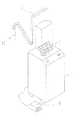
以下、図面に基づいて本発明の実施形態を説明する。図1はレーザメスによる切開手術等を行うレーザ治療装置の外観略図を示したものであり、図2は装置の制御系及び光学系の要部図を示したものである。 Hereinafter, embodiments of the present invention will be described with reference to the drawings. FIG. 1 is a schematic external view of a laser treatment apparatus that performs an incision operation or the like using a laser knife, and FIG. 2 is a principal view of the control system and optical system of the apparatus.
1はレーザ装置本体であり、レーザ装置本体1内には治療用レーザ光源51、エイミング光源52、エイミング光源52からのレーザ光を平行光にするコリメーティングレンズ53、制御部50等が収納されている。本実施形態の装置では、治療用レーザ光源51には赤外のパルスレーザ光を出射するCO2レーザ光源を、エイミング光源52には赤色光を出射する半導体レーザを使用している。2は多関節アーム部、10はハンドピースユニット、7はレーザ照射条件等の各種設定条件を入力するためのコントロールパネル、8はトリガ信号を発信させるためのフットスイッチである。
多関節アーム部2は数本の剛体管が駆動可能なように関節部によって連結されており、術者はハンドピースユニット10を自由に移動させることができる。多関節アーム部2の各関節部にはミラーが配置されており、レーザ装置本体1から出射された治療用レーザ光及びエイミング光を多関節アーム部2内を通過させてハンドピースユニット10まで導光する。尚、レーザ光源51からの治療用レーザ光は平行光であり、エイミング光はコリメーティングレンズ53により平行光にされているので、多関節アーム部2内も平行光で導光されている。 The
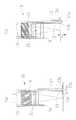
図3はハンドピースユニット10下部の断面図を示したものである。ハンドピースユニット10は、ハンドピース本体11と、皮膚に当接させてハンドピース本体11を治療部位上で支持すると共に、ハンドピース本体11から治療部位までの距離を定めるためのディスタンスガイド部材としての軸状のチップ12を備える。チップ12の外径は本実施形態では1.5mmはであるが、これに限定されるものではない。チップ12の先端部12aは、皮膚上でスムーズに移動するように、曲面上に面取りされている。 FIG. 3 shows a sectional view of the lower part of the
ハンドピース本体11にはレーザ光を治療部位に照射するための照射光学系としての集光レンズ15が設けられている。13は、レーザ光を集光する集光レンズ15を保持し、チップ12の先端部12aを皮膚に押し付けた際に皮膚からの反力により、集光レンズ15と共にその光軸方向に移動する移動支基(第2のディスタンスガイド部材)である。移動支基13は軽量にするため、ナイロン等の樹脂で作られている。また、移動支基13の先端部13aは、皮膚との接触面が大きくなるようにフランジ状に曲げられている。チップ12で皮膚を押さえた時に皮膚の凹凸の影響を受けないように、先端部13aのフランジ部の直径Dは7mm以上あることが好ましく、本実施の形態では、直径Dは8mmとしている。フランジ部の形状を本実施の形態では円形としたが、円形に限らず、楕円形状等の他の形状であってもよい。移動支基13の先端部13aを治療部位周辺(近傍)上に当接することにより、集光レンズ15と治療部位との距離を略一定に保つことができる。これにより集光レンズ15によって集光されるレーザ光の焦点位置を治療部位上に置くことができ、レーザ光は治療部位上で所定のスポット径とされる。多関節アーム部2から集光レンズ15までは平行光で導光されているので、集光レンズ15の位置が変化しても、集光レンズ15の焦点位置に照射スポットを集光することが可能である。 The handpiece
また、チップ12の先端部12aを治療部位周辺に当てることでハンドピースユニット10のぐらつきを軽減し、安定した状態にて治療用レーザ光を照射することが可能である。 Further, the wobbling of the
また、ハンドピース本体11と移動支基13の間には圧縮バネ14が入れられており、移動支基13をレーザ光の照射方向(集光レンズ15の光軸方向)の治療面側に付勢している。圧縮バネ14により移動支基13は治療面側に付勢されているが、その付勢力は皮膚を押し付けても皮膚が沈み込まない程度の弱い力で押さえられている。付勢力はバネの変形量により異なるが、最大でも50g以下であることが好ましい。本実施の形態では、最大でも付勢力が30g以下となるバネが用いられている。尚、圧縮バネ14の付勢力で移動支基13がハンドピース本体11から抜け落ちないように、ハンドピース本体11には留め金具16が固定されている。この留め金具16により、移動支基13の先端部13aが皮膚側に移動可能な位置は、チップ12の先端部12aと同じ位置とされている。 Further, a
次に、以上のような構成を備えるレーザ治療装置において、その動作について図2の制御系ブロック図を使用して説明する。 Next, the operation of the laser treatment apparatus having the above configuration will be described using the control system block diagram of FIG.
術者は、レーザ出力や照射スポット径の大きさ、照射密度等の照射条件をコントロールパネル7上の各スイッチで設定する。ハンドピースユニット10のスポット径の異なるものが複数あり、スポット径の異なるハンドピースユニットを使用する場合は、その照射スポット径はスイッチ7aで設定することができる。 The surgeon sets the irradiation conditions such as the laser output, the size of the irradiation spot diameter, and the irradiation density with the switches on the
必要な条件設定が完了したら、従者はハンドピースユニット10を持ち、図3(a)の様にチップ12の先端部12a及び移動支基13の先端部13aを切開したい治療部位近くの皮膚に当接させる。皮膚に押し付けると、皮膚からの反力が先端部13aに加わり、図3(b)に示す様に、移動支基13及び集光レンズ15は、皮膚と反対方向に移動し(図3(b)におけるチップ12の沈み込み高さhだけ移動する)、皮膚と集光レンズ15の距離が略一定に保たれる。移動支基13の先端部13aは、フランジ状になっているので、先端部13aがチップ9の先端部12aと共に皮膚に沈み込むことはない。 When the necessary condition setting is completed, the attendant holds the
術者の所望する力でチップ12を皮膚に押し当てることができるので、ハンドピースユニット10のぐらつきをなくし、安定して治療を行うことができる。また、集光レンズ15によって集光されるレーザ光の焦点位置を治療部位上に置くことができるので、レーザ光は治療部位上で所望するのスポット径とすることができる。特に、スポット径がφ0.1mmと小さいレーザメスの使用の場合は焦点深度が浅くなり、照射距離の変化がスポット径の変化に顕著に現れるので、特にスポット径を一定に保つ点で有効である。スポット径を一定に保つことにより、レーザメスの切れ味を良くして皮膚を切開した断面を良好にすることができる。また眼瞼下垂の治療のように、瞼のようなやわらかい皮膚にチップ12を押し当て、皮膚が沈み込んでも、移動支基13と共に移動する集光レンズ15によって集光されるレーザ光の焦点位置を常に治療部位上に置くことができるので、安定して治療することができる。 Since the
また、ハンドピース本体11と移動支基13の間には圧縮バネ14が入れられているので、ハンドピース本体11を垂直方向に立てて使用しなくてもよく、垂直方向から水平方向の範囲において使用することができる。 Further, since the
上記で述べたように、本発明によれば、患部の皮膚の硬さによらず、一定のスポット径で照射を行うことができる。また、ハンドピースを押し当てる力に左右されず、術者の個人差に左右されないで、レーザ照射を行うことができる。 As described above, according to the present invention, irradiation can be performed with a constant spot diameter regardless of the skin hardness of the affected area. Further, laser irradiation can be performed without being influenced by the force of pressing the handpiece and without being influenced by individual differences of the operator.
ハンドピースユニット3からはエイミング光源52によるエイミング光が照射されるので、術者はエイミング光の照射位置を確認し、切開したい部位に照準合わせをする。照準合わせができたら、コントロールパネル7のスイッチ7bによりレーザ光源51の発振状態をスタンバイモードからレディモードに切替え、レーザ照射指示を行うためにフットスイッチ8によりトリガ信号を発振させる。トリガ信号を受けた制御部50は、レーザ光源51を駆動制御して治療用レーザ光を出射させる。レーザ光源51を出射した治療用レーザ光は、ミラー54、ダイクロイックミラー55によって反射された後、エイミング光源52より出射されているエイミング光と同軸にされ、多関節アーム部2に入射する。多関節アーム部2内に入射した治療用レーザ光(及びエイミング光)は各間接部に設けられたミラーによって反射されながらハンドピースユニット10に導光され、集光レンズ15により所期するスポット径で切開部位に照射される。術者は、ハンドピースユニット10を患者の皮膚に接触させながら切開したい方向に移動し治療を行う。 Since the aiming light from the aiming
上記の実施形態ではディスタンスガイド部材としてのチップ12をハンドピース本体11に設けた構成で説明したが、これは無くても良く、集光レンズ15と共にその光軸方向に移動可能なディスタンスガイド部材である移動支基13のみで構成しても良い。 In the above-described embodiment, the
1 レーザ装置本体
2 多関節アーム部
10 ハンドピースユニット
12 チップ
12a 先端部
13 移動支基
13a 先端部
14 圧縮バネ
15 集光レンズ
51 治療用レーザ光源
DESCRIPTION OF
Claims (3)
Translated fromJapaneseIn a laser treatment apparatus that irradiates the skin with laser light from a therapeutic laser light source, a handpiece having an irradiation optical system for irradiating laser light to a predetermined position, and a distance from the irradiation optical system to the treatment site A distance guide member that abuts against the skin to determine, and the distance guide is movable along the optical axis along with the irradiation optical system by the reaction force from the skin when abutting against the skin. A laser treatment apparatus, wherein the handpiece is provided with urging means that is held and urges the distance guide member and the irradiation optical system toward the skin.
Priority Applications (1)
| Application Number | Priority Date | Filing Date | Title |
|---|---|---|---|
| JP2003357054AJP4421259B2 (en) | 2003-10-16 | 2003-10-16 | Laser therapy device |
Applications Claiming Priority (1)
| Application Number | Priority Date | Filing Date | Title |
|---|---|---|---|
| JP2003357054AJP4421259B2 (en) | 2003-10-16 | 2003-10-16 | Laser therapy device |
Publications (2)
| Publication Number | Publication Date |
|---|---|
| JP2005118325Atrue JP2005118325A (en) | 2005-05-12 |
| JP4421259B2 JP4421259B2 (en) | 2010-02-24 |
Family
ID=34614053
Family Applications (1)
| Application Number | Title | Priority Date | Filing Date |
|---|---|---|---|
| JP2003357054AExpired - Fee RelatedJP4421259B2 (en) | 2003-10-16 | 2003-10-16 | Laser therapy device |
Country Status (1)
| Country | Link |
|---|---|
| JP (1) | JP4421259B2 (en) |
Cited By (9)
| Publication number | Priority date | Publication date | Assignee | Title |
|---|---|---|---|---|
| JP2007319475A (en)* | 2006-06-01 | 2007-12-13 | Shibuya Kogyo Co Ltd | Laser treatment apparatus |
| WO2008102428A1 (en)* | 2007-02-19 | 2008-08-28 | The Graduate School For The Creation Of New Photonics Industries | Skull cut-off device |
| JP2011512914A (en)* | 2008-02-29 | 2011-04-28 | ルメラ レーザー ゲーエムベーハー | Laser processing equipment for processing biological tissue |
| WO2016154408A1 (en)* | 2015-03-25 | 2016-09-29 | East Carolina University | A laser safety adaptor for use in laser based imaging systems and related devices |
| US10058256B2 (en) | 2015-03-20 | 2018-08-28 | East Carolina University | Multi-spectral laser imaging (MSLI) methods and systems for blood flow and perfusion imaging and quantification |
| US10390718B2 (en) | 2015-03-20 | 2019-08-27 | East Carolina University | Multi-spectral physiologic visualization (MSPV) using laser imaging methods and systems for blood flow and perfusion imaging and quantification in an endoscopic design |
| US10722173B2 (en) | 2014-10-14 | 2020-07-28 | East Carolina University | Methods, systems and computer program products for visualizing anatomical structures and blood flow and perfusion physiology using imaging techniques |
| US10792492B2 (en) | 2014-10-14 | 2020-10-06 | East Carolina University | Methods, systems and computer program products for determining physiologic status parameters using signals derived from multispectral blood flow and perfusion imaging |
| US11553844B2 (en) | 2014-10-14 | 2023-01-17 | East Carolina University | Methods, systems and computer program products for calculating MetaKG signals for regions having multiple sets of optical characteristics |
Families Citing this family (1)
| Publication number | Priority date | Publication date | Assignee | Title |
|---|---|---|---|---|
| KR101940155B1 (en) | 2017-08-30 | 2019-01-18 | 주식회사 이루다 | Laser treatment device assembled with grinder |
- 2003
- 2003-10-16JPJP2003357054Apatent/JP4421259B2/ennot_activeExpired - Fee Related
Cited By (12)
| Publication number | Priority date | Publication date | Assignee | Title |
|---|---|---|---|---|
| JP2007319475A (en)* | 2006-06-01 | 2007-12-13 | Shibuya Kogyo Co Ltd | Laser treatment apparatus |
| WO2008102428A1 (en)* | 2007-02-19 | 2008-08-28 | The Graduate School For The Creation Of New Photonics Industries | Skull cut-off device |
| JP5193178B2 (en)* | 2007-02-19 | 2013-05-08 | 学校法人光産業創成大学院大学 | Skull cutting device |
| US8790333B2 (en) | 2007-02-19 | 2014-07-29 | The Graduate for the Creation of New Photonics Industries | Skull cutting device |
| JP2011512914A (en)* | 2008-02-29 | 2011-04-28 | ルメラ レーザー ゲーエムベーハー | Laser processing equipment for processing biological tissue |
| US10722173B2 (en) | 2014-10-14 | 2020-07-28 | East Carolina University | Methods, systems and computer program products for visualizing anatomical structures and blood flow and perfusion physiology using imaging techniques |
| US10792492B2 (en) | 2014-10-14 | 2020-10-06 | East Carolina University | Methods, systems and computer program products for determining physiologic status parameters using signals derived from multispectral blood flow and perfusion imaging |
| US11553844B2 (en) | 2014-10-14 | 2023-01-17 | East Carolina University | Methods, systems and computer program products for calculating MetaKG signals for regions having multiple sets of optical characteristics |
| US10058256B2 (en) | 2015-03-20 | 2018-08-28 | East Carolina University | Multi-spectral laser imaging (MSLI) methods and systems for blood flow and perfusion imaging and quantification |
| US10390718B2 (en) | 2015-03-20 | 2019-08-27 | East Carolina University | Multi-spectral physiologic visualization (MSPV) using laser imaging methods and systems for blood flow and perfusion imaging and quantification in an endoscopic design |
| WO2016154408A1 (en)* | 2015-03-25 | 2016-09-29 | East Carolina University | A laser safety adaptor for use in laser based imaging systems and related devices |
| CN107438927A (en)* | 2015-03-25 | 2017-12-05 | 东卡罗莱娜大学 | For the laser safety adapter used in the imaging system based on laser and related device |
Also Published As
| Publication number | Publication date |
|---|---|
| JP4421259B2 (en) | 2010-02-24 |
Similar Documents
| Publication | Publication Date | Title |
|---|---|---|
| US10092445B2 (en) | Ophthalmologic device for breaking down eye tissue | |
| JP4034941B2 (en) | Laser therapy device | |
| US9427822B2 (en) | Laser treatment device | |
| CN115666434A (en) | Active alignment system for improving optical coupling of multiplexer of laser-driven intravascular lithotripsy device | |
| JP4421259B2 (en) | Laser therapy device | |
| JP2006051101A (en) | Corneal surgery apparatus | |
| JPH11514246A (en) | Handheld laser scanner | |
| CN211213643U (en) | Oral cavity laser treatment equipment capable of automatically focusing and adjusting spot size | |
| JP2015500049A (en) | Laser method and apparatus for ophthalmology | |
| JP4492845B2 (en) | Laser treatment device | |
| JP2003164534A (en) | Laser therapeutic instrument | |
| JP2001259877A (en) | Optical system for laser beam emission and method of laser machining | |
| JP7232755B2 (en) | laser sternotomy | |
| JP2603504B2 (en) | Medical laser device | |
| JPH0738189A (en) | Laser apparatus | |
| JP2007319475A (en) | Laser treatment apparatus | |
| JP2002200180A5 (en) | ||
| JP2003319947A (en) | Laser therapeutic apparatus | |
| JP2003000613A (en) | Laser therapeutic device | |
| KR102517435B1 (en) | The fractional laser for the skin beauty | |
| JPS6033929Y2 (en) | Laser scalpel attachment | |
| JP2004113609A (en) | Laser therapeutic apparatus | |
| JP2000152954A5 (en) | ||
| JP2003339890A (en) | Laser therapy equipment | |
| JPH03111040A (en) | Laser medical treatment device |
Legal Events
| Date | Code | Title | Description |
|---|---|---|---|
| A621 | Written request for application examination | Free format text:JAPANESE INTERMEDIATE CODE: A621 Effective date:20060812 | |
| A131 | Notification of reasons for refusal | Free format text:JAPANESE INTERMEDIATE CODE: A131 Effective date:20090811 | |
| A521 | Written amendment | Free format text:JAPANESE INTERMEDIATE CODE: A523 Effective date:20091013 | |
| TRDD | Decision of grant or rejection written | ||
| A01 | Written decision to grant a patent or to grant a registration (utility model) | Free format text:JAPANESE INTERMEDIATE CODE: A01 Effective date:20091106 | |
| A01 | Written decision to grant a patent or to grant a registration (utility model) | Free format text:JAPANESE INTERMEDIATE CODE: A01 | |
| A61 | First payment of annual fees (during grant procedure) | Free format text:JAPANESE INTERMEDIATE CODE: A61 Effective date:20091202 | |
| FPAY | Renewal fee payment (event date is renewal date of database) | Free format text:PAYMENT UNTIL: 20121211 Year of fee payment:3 | |
| R150 | Certificate of patent or registration of utility model | Free format text:JAPANESE INTERMEDIATE CODE: R150 | |
| LAPS | Cancellation because of no payment of annual fees |