JP2005114860A - Ferrule for optical connector and method of assembling optical connector - Google Patents
Ferrule for optical connector and method of assembling optical connectorDownload PDFInfo
- Publication number
- JP2005114860A JP2005114860AJP2003346220AJP2003346220AJP2005114860AJP 2005114860 AJP2005114860 AJP 2005114860AJP 2003346220 AJP2003346220 AJP 2003346220AJP 2003346220 AJP2003346220 AJP 2003346220AJP 2005114860 AJP2005114860 AJP 2005114860A
- Authority
- JP
- Japan
- Prior art keywords
- ferrule
- optical fiber
- pressing member
- optical
- fiber core
- Prior art date
- Legal status (The legal status is an assumption and is not a legal conclusion. Google has not performed a legal analysis and makes no representation as to the accuracy of the status listed.)
- Pending
Links
- 230000003287optical effectEffects0.000titleclaimsabstractdescription89
- 238000000034methodMethods0.000titleclaimsabstractdescription17
- 239000013307optical fiberSubstances0.000claimsabstractdescription136
- 238000003825pressingMethods0.000claimsabstractdescription74
- 238000003780insertionMethods0.000claimsdescription54
- 230000037431insertionEffects0.000claimsdescription54
- 239000003795chemical substances by applicationSubstances0.000claimsdescription14
- 238000002347injectionMethods0.000claimsdescription6
- 239000007924injectionSubstances0.000claimsdescription6
- 230000000149penetrating effectEffects0.000claims1
- 239000000835fiberSubstances0.000description4
- 229920005989resinPolymers0.000description3
- 239000011347resinSubstances0.000description3
- MCMNRKCIXSYSNV-UHFFFAOYSA-NZirconium dioxideChemical compoundO=[Zr]=OMCMNRKCIXSYSNV-UHFFFAOYSA-N0.000description2
- 229910052782aluminiumInorganic materials0.000description2
- XAGFODPZIPBFFR-UHFFFAOYSA-NaluminiumChemical compound[Al]XAGFODPZIPBFFR-UHFFFAOYSA-N0.000description2
- 239000000463materialSubstances0.000description2
- 229910052751metalInorganic materials0.000description2
- 239000002184metalSubstances0.000description2
- 239000000853adhesiveSubstances0.000description1
- 230000001070adhesive effectEffects0.000description1
- 230000002411adverseEffects0.000description1
- 238000005452bendingMethods0.000description1
- 239000000919ceramicSubstances0.000description1
- 210000000078clawAnatomy0.000description1
- 230000008878couplingEffects0.000description1
- 238000010168coupling processMethods0.000description1
- 238000005859coupling reactionMethods0.000description1
- 239000003822epoxy resinSubstances0.000description1
- 238000009434installationMethods0.000description1
- 230000002093peripheral effectEffects0.000description1
- 239000004033plasticSubstances0.000description1
- 229920000647polyepoxidePolymers0.000description1
- 238000002360preparation methodMethods0.000description1
- 230000001105regulatory effectEffects0.000description1
- 229920001187thermosetting polymerPolymers0.000description1
Images


Landscapes
- Mechanical Coupling Of Light Guides (AREA)
Abstract
Translated fromJapaneseDescription
Translated fromJapanese本発明は、光ケーブル同士や光送受信装置などの光接続を可能にしている光コネクタの内部で利用されるフェルール及び、このフェルールがハウジング内に組み込まれた光コネクタを組み立てる方法に関するものである。 The present invention relates to a ferrule used inside an optical connector that enables optical connection between optical cables and an optical transceiver, and a method of assembling an optical connector in which the ferrule is incorporated in a housing.
従来から一般的に採用されている光コネクタとしては、特開平10−170756号公報、特開平11−160563号公報がある。この公報に記載された光コネクタは、いわゆる「メカニカルスプライス」と呼ばれており、敷設現場などで簡易にかつ短時間で組み立てが完了することに配慮されている。このような現地組立て式光コネクタでは、円筒状のフェルールの後端にメカニカルスプライス部が連結されており、このメカニカルスプライス部は、断面V字状の光ファイバ挿入溝が設けられたベース部材と、光ファイバ挿入溝を塞ぐようにベース部材に押し当てられるカバー部材と、ベース部材及びカバー部材を挟み込むバネ性のクランプ部材とからなる。 As optical connectors that have been generally employed, there are JP-A-10-170756 and JP-A-11-160563. The optical connector described in this publication is called a so-called “mechanical splice”, and it is considered that the assembly can be completed easily and in a short time at an installation site or the like. In such a field assembly type optical connector, a mechanical splice portion is connected to the rear end of the cylindrical ferrule, and the mechanical splice portion includes a base member provided with an optical fiber insertion groove having a V-shaped cross section, The cover member is pressed against the base member so as to close the optical fiber insertion groove, and the spring-like clamp member sandwiches the base member and the cover member.
このような光コネクタを現場で組み立てる際、先ず、クサビ部材をメカニカルスプライス部に差し込んで、ベース部材とカバー部材との分割部分を拡張し、光ファイバ挿入溝を開放させる。その後、光ファイバ挿入溝の後端側から光ケーブルの光ファイバ心線を差し込んで、この光ファイバ心線の先端をフェルール内の光ファイバ心線の後端に突き当てる。その後、クサビ部材を引き抜くことにより、ベース部材とカバー部材とで各光ファイバ心線が挟み込まれ、フェルール側の光ファイバ心線と光ケーブル側の光ファイバ心線とがメカニカルスプライス部において結合される。その後、フェルール及びメカニカルスプライス部を覆うようにプラスチック製のハウジングを装着し、光コネクタの組立ては完了する。 When assembling such an optical connector in the field, first, the wedge member is inserted into the mechanical splice part, the divided part of the base member and the cover member is expanded, and the optical fiber insertion groove is opened. Thereafter, the optical fiber core of the optical cable is inserted from the rear end side of the optical fiber insertion groove, and the tip of the optical fiber core is abutted against the rear end of the optical fiber core in the ferrule. Then, by pulling out the wedge member, each optical fiber core wire is sandwiched between the base member and the cover member, and the optical fiber core wire on the ferrule side and the optical fiber core wire on the optical cable side are coupled at the mechanical splice portion. Thereafter, a plastic housing is mounted so as to cover the ferrule and the mechanical splice, and the assembly of the optical connector is completed.
このようなメカニカルスプライス式の光コネクタを屋内の光コンセントやローゼットなどで利用する場合、規格などによって光コネクタの全長が規制される場合がある。しかしながら、従来の光コネクタでは、フェルールの後方にメカニカルスプライス部を有しているので、光コネクタの全長が長くなってしまうので、寸法的な制限が多い屋内で利用し難いといった問題点があった。 When such a mechanical splice type optical connector is used in an indoor optical outlet or a rosette, the total length of the optical connector may be regulated by standards or the like. However, since the conventional optical connector has a mechanical splice portion behind the ferrule, the total length of the optical connector becomes long, so that there is a problem that it is difficult to use indoors with many dimensional restrictions. .
本発明は、部品点数の削減による小型化を可能にした光コネクタ用フェルール及びこのようなフェルールを利用した光コネクタ組立方法を提供することを目的とする。 An object of the present invention is to provide a ferrule for an optical connector that can be miniaturized by reducing the number of parts, and an optical connector assembling method using such a ferrule.
本発明に係る光コネクタ用フェルールは、内部に光ファイバ心線が内蔵された光コネクタ用フェルールにおいて、光ファイバ心線の後端から後方に向けて延在する第1の光ファイバ挿入溝を有すると共に、第1の光ファイバ挿入溝の位置に設けられた切欠き部を有するフェルール本体と、第1の光ファイバ挿入溝を覆うように切欠き部に装填される押さえ部材と、フェルール本体の長手方向に沿って前後方向に摺動すると共に、フェルール本体に押さえ部材を載置させた状態で、前進時においてフェルール本体に押さえ部材を圧着させ、後退時においてフェルール本体から押さえ部材を解放させるリング部材とを備えたことを特徴とする。 The ferrule for optical connectors according to the present invention has a first optical fiber insertion groove extending rearward from the rear end of the optical fiber core wire in the ferrule for optical connector in which the optical fiber core wire is incorporated. In addition, a ferrule body having a notch provided at the position of the first optical fiber insertion groove, a pressing member loaded in the notch so as to cover the first optical fiber insertion groove, and a longitudinal direction of the ferrule body A ring member that slides in the front-rear direction along the direction, presses the pressing member against the ferrule body when moving forward, and releases the pressing member from the ferrule body when moving backward while the pressing member is placed on the ferrule body. It is characterized by comprising.
本発明に係る光コネクタ用フェルールでは、その内部に光ファイバ心線の接続点が設けられ、フェルール自体にメカニカルスプライス部分を搭載しているので、フェルールの小型化を可能にする。このフェルールには、フェルール本体の長手方向に沿って進退するリング部材が設けらており、このリング部材をフェルール本体に沿って前進させると、フェルール本体に押さえ部材が圧着される。従って、フェルール本体と押さえ部材との間に光ケーブル側の光ファイバ心線を配置させた状態で、リング部材を前進させることで、フェルール本体と押さえ部材とで光ファイバ心線を挟み込むことができる。これに対し、リング部材を後退させることで、フェルール本体から押さえ部材が解放され、光ケーブル側の光ファイバ心線をフェルールから抜き出すことができる。このように、フェルール本体に沿って摺動するリング部材をフェルール自体が有することで、フェルールに対して光ケーブルの着脱をワンタッチで行うことができ、作業性が極めて良好になる。 In the ferrule for an optical connector according to the present invention, the connection point of the optical fiber core wire is provided therein, and the mechanical splice portion is mounted on the ferrule itself, so that the ferrule can be miniaturized. The ferrule is provided with a ring member that advances and retreats along the longitudinal direction of the ferrule body. When the ring member is advanced along the ferrule body, a pressing member is pressure-bonded to the ferrule body. Therefore, the optical fiber core wire can be sandwiched between the ferrule main body and the pressing member by advancing the ring member in a state where the optical fiber core wire on the optical cable side is disposed between the ferrule main body and the pressing member. On the other hand, by retracting the ring member, the pressing member is released from the ferrule body, and the optical fiber core on the optical cable side can be extracted from the ferrule. Thus, since the ferrule itself has a ring member that slides along the ferrule body, the optical cable can be attached to and detached from the ferrule with one touch, and the workability is extremely good.
また、フェルール本体と押さえ部材との間に形成された分割部分において、押さえ部材に設けられた分割面には、変形可能な脚部が設けられていると好適である。変形可能な脚部の採用により、フェルール本体と押さえ部材との間の分割部分に予め所定の隙間をもたせておくことができ、分割部分に光ファイバ心線を容易に装填することができる。また、脚部ゆえに、リング部材を介して押さえ部材に印加された荷重によって変形が容易である。 Further, in the divided portion formed between the ferrule body and the pressing member, it is preferable that a deformable leg portion is provided on the divided surface provided on the pressing member. By adopting the deformable leg portion, a predetermined gap can be provided in advance in the divided portion between the ferrule body and the pressing member, and the optical fiber core wire can be easily loaded in the divided portion. Further, because of the leg portion, the deformation is easy due to the load applied to the pressing member via the ring member.
また、押さえ部材の後端部において、押さえ部材の外面には、押さえ部材の後端から前方に向けて延在する上り勾配をもって形成されたテーパ面が設けられ、リング部材の前進時にリング部材の前端は、テーパ面に乗り上げながら押さえ部材をフェルール本体に圧着させると好適である。テーパ面の採用により、リング部材をフェルール本体から押さえ部材へスムーズに移行させることができる。 Further, at the rear end portion of the pressing member, the outer surface of the pressing member is provided with a tapered surface formed with an upward slope extending forward from the rear end of the pressing member, and when the ring member moves forward, The front end is preferably formed by pressing the pressing member onto the ferrule body while riding on the tapered surface. By adopting the tapered surface, the ring member can be smoothly transferred from the ferrule body to the pressing member.
また、テーパ面は、第1の光ファイバ挿入溝に対して3〜20度の角度をもって延在すると好適である。このようなテーパ面の採用により、押さえ部材に徐々に荷重を加えることができるので、光ファイバ心線に悪影響を及ぼす急激な力の印加を防止することができる。 Further, it is preferable that the tapered surface extends with an angle of 3 to 20 degrees with respect to the first optical fiber insertion groove. By adopting such a tapered surface, it is possible to gradually apply a load to the pressing member, so that it is possible to prevent a sudden force from being exerted on the optical fiber core wire.
また、テーパ面の前端の位置は、光ファイバ心線の後端に対応する位置より後方であると好適である。これは、フェルール内における光ファイバ心線の接続点で光ファイバ心線同士を確実に結合させることを考慮した発明である。 Moreover, it is preferable that the position of the front end of the tapered surface is behind the position corresponding to the rear end of the optical fiber core wire. This is an invention in consideration of reliably coupling optical fiber cores at a connection point of optical fiber cores in a ferrule.
また、第1の光ファイバ挿入溝に対して直交する方向で光ファイバ心線の後端に向けて延在すると共に、外部から第1の光ファイバ挿入溝まで貫通する屈折率整合剤注入孔を更に備えると好適である。このような構成は、フェルールの内部へ屈折率整合剤の注入を可能にしているので、光ケーブルの再接続を可能にする。 Further, a refractive index matching agent injection hole extending from the outside to the first optical fiber insertion groove and extending toward the rear end of the optical fiber core wire in a direction orthogonal to the first optical fiber insertion groove. It is preferable to further provide. Such a configuration allows the refractive index matching agent to be injected into the interior of the ferrule, thus allowing the optical cable to be reconnected.
また、押さえ部材の分割面には、第1の光ファイバ挿入溝に対向するように延在する断面V字状の第2の光ファイバ挿入溝が形成されていると好適である。断面V字状の第2の光ファイバ挿入溝を採用することによって、フェルール内で光ケーブル側の光ファイバ心線を確実に保持することができる。 Further, it is preferable that a second optical fiber insertion groove having a V-shaped cross section extending so as to face the first optical fiber insertion groove is formed on the split surface of the pressing member. By adopting the second optical fiber insertion groove having a V-shaped cross section, the optical fiber core on the optical cable side can be reliably held in the ferrule.
光コネクタ組立方法においては、請求項1記載のフェルールがハウジング内に組み込まれた光コネクタを組み立てる方法であって、光ケーブルの先端の外被を除去して光ファイバ心線を露出させる工程と、フェルール本体に設けられた第1の光ファイバ挿入溝に沿ってフェルールの後端から光ファイバ心線を挿入して、フェルール内に予め内蔵されている光ファイバ心線の後端に光ファイバ心線を当接させる工程と、リング部材を前進させてフェルール本体に押さえ部材を圧着させる工程とを備えたことを特徴とする。この方法は、光コネクタの初回の組立てに利用される。 An optical connector assembling method is a method of assembling an optical connector in which the ferrule according to
光コネクタ組立方法においては、請求項1記載のフェルールがハウジング内に組み込まれた光コネクタを組み立てる方法であって、フェルール本体から押さえ部材を解放させるためにリング部材を後退させる工程と、光ケーブルの光ファイバ心線をフェルールの後端から抜き出す工程と、フェルール内に予め内蔵されている光ファイバ心線の後端に屈折率整合剤を付着させる工程と、光ケーブルの光ファイバ心線の先端を切断する工程と、フェルール本体に設けられた第1の光ファイバ挿入溝に沿ってフェルールの後端から光ファイバ心線を挿入して、フェルール内に予め内蔵されている光ファイバ心線の後端に光ファイバ心線を当接させる工程と、リング部材を前進させてフェルール本体に押さえ部材を圧着させる工程とを備えたことを特徴とする。この方法は、光コネクタの再度の組立てに利用される。 An optical connector assembling method is a method for assembling an optical connector in which the ferrule according to
本発明に係るフェルールは小型化を可能にしている。本発明に係る光コネクタ組立方法によれば、フェルールの小型化に伴ってハウジングの小型化を可能にし、小型化された光コネクタに光ケーブル側の光ファイバ心線を装着することができる。 The ferrule according to the present invention enables miniaturization. According to the optical connector assembling method of the present invention, the housing can be miniaturized as the ferrule is miniaturized, and the optical fiber core on the optical cable side can be attached to the miniaturized optical connector.
以下、図面を参照しつつ本発明に係る光コネクタ用フェルール及び光コネクタ組立方法の好適な実施形態について詳細に説明する。 DESCRIPTION OF EMBODIMENTS Hereinafter, preferred embodiments of an optical connector ferrule and an optical connector assembling method according to the present invention will be described in detail with reference to the drawings.
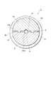
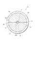
図1及び図2に示すように、光コネクタ用フェルール1は、単心用として利用されると共に、ジルコニアセラミックからなる直径2.5mm程度の円筒状のフェルール本体2を有している。このフェルール本体2の中央部には半円柱状に切り欠かれた切欠き部4が形成され、フェルール本体2の後部には円筒状のガイド部3が形成されている。そして、フェルール本体2の外周面にはリング状のフランジ部5が圧入によって固定されている。 As shown in FIGS. 1 and 2, an
さらに、フェルール本体2の中心には、前端面2aから内部に向かって延在する光ファイバ装填孔6が形成され、この光ファイバ装填孔6内には、接着剤を介して光ファイバ心線7が固定されている。また、切欠き部4によってフェルール本体2の後部に形成された第1の分割面2bには、光ファイバ装填孔6に対して一直線上に整列させた断面半円状の第1の光ファイバ挿入溝8が形成され、ガイド部3には、第1の光ファイバ挿入溝8に対して一直線上に整列させた光ファイバ挿入孔9が形成されている。そして、光ファイバ心線7の後端は、第1の光ファイバ挿入溝8内に挿入され、これによって、光ファイバ心線7の後端から後方に向けて第1の光ファイバ挿入溝8が延在することになる。なお、フェルール本体2の前端面2aから突出した光ファイバ心線7の余剰部分は、前端面2aの研磨加工の際に除去される。 Further, an optical
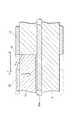
さらに、フェルール1は、第1の光ファイバ挿入溝8を覆うように切欠き部4に装填される半円柱状の押さえ部材10を有している。この押さえ部材10の第2の分割面10aには、第1の光ファイバ挿入溝8に対向するように断面V字状の第2の光ファイバ挿入溝11が形成され、第2の光ファイバ挿入溝11を断面V字状に形成することで、後述する光ファイバ心線20aの位置決め及び保持が確実に達成される。そして、断面半円状の第1の光ファイバ挿入溝8と断面V字状の第2の光ファイバ挿入溝11と断面円形の光ファイバ挿入孔9との協働で光ファイバ挿入路13が形成される。 Further, the
さらに、押さえ部材10をフェルール本体2の切欠き部4に装填させると、フェルール本体2側の第1の分割面2bと押さえ部材10側の第2の分割面10aとの協働で分割部分Sが形成され、この分割部分Sは、図4に示すように、押さえ部材10側の第2の分割面10aに設けられた2本の脚部14によって確保され、一対の脚部14は、互いに平行であると共に、押さえ部材10に一体的に形成されている。脚部14による分割部分Sの高さが確保されることで、光ケーブル20(図3参照)側の光ファイバ心線20aは、光ファイバ挿入路13を通ってフェルール1内に容易に挿入することができる。 Further, when the
これに対し、図5に示すように、押さえ部材10の加圧によって、脚部14が押し潰された場合には、光ファイバ心線20aは、1の光ファイバ挿入溝8と断面V字状の第2の光ファイバ挿入溝11とで挟み込まれる。この加圧を達成するため、フェルール1は、フェルール本体2のガイド部3の長手方向に沿って前後方向に摺動可能である金属製のリング部材12を有し、このリング部材12は、押さえ部材10をフェルール本体2に押圧する。そこで、フェルール本体2に押さえ部材10を載置させた状態で、リング部材12をガイド部3から押さえ部材10に向けて前進させると、フェルール本体2に押さえ部材10が圧着され、リング部材12を押さえ部材10からガイド部3に向けて後退させると、フェルール本体2から押さえ部材10が解放される。従って、リング部材12の採用により、フェルール1に対して光ケーブル20の着脱をワンタッチで行うことができ、作業性が極めて良好になる。そして、このようなリング部材12と押さえ部材10とでメカニカルスプライス部分Mが構成される。 On the other hand, as shown in FIG. 5, when the
メカニカルスプライス部分Mに利用される押さえ部材10には、塑性変形可能で且つ弾性変形可能な部材としてアルミニウムが利用される。また、押さえ部材10を熱硬化型エポキシ樹脂で形成すると、フェルール本体2と押さえ部材10とで挟み込まれた光ファイバ心線20a(図3参照)に発生し易いクリープ現象を抑制することができる。変形可能な脚部14の採用により、フェルール本体2と押さえ部材10との間の分割部分Sに予め所定の隙間を維持させておくことができるので、分割部分Sに光ファイバ心線20aを容易に挿入することができる(図4参照)。また、脚部14は長手方向に細長い形状ゆえに、リング部材12を介して押さえ部材10に加えられた荷重によって容易に変形することができる(図5参照)。 For the pressing
さらに、図6に示すように、押さえ部材10をリング部材12によって適切に加圧する必要がある。そこで、押さえ部材10の後端部において、押さえ部材10の外面には、押さえ部材10の後端から前方に向けて延在する上り勾配をもって形成されたテーパ面16が設けられている。従って、リング部材12の前進時において、リング部材12の前端は、テーパ面16に乗り上げながら押さえ部材10をフェルール本体2に圧着させることができる。このとき、押さえ部材10はフェルール本体2に向けて所定量だけ押し下げられ、このことによって、脚部14が潰されることになる。このようなテーパ面16の採用により、リング部材12をフェルール本体2から押さえ部材10へスムーズに移行させることができる。 Furthermore, as shown in FIG. 6, it is necessary to appropriately press the pressing
さらに、テーパ面16は、第1の光ファイバ挿入溝8に対して3〜20度の角度αをもって延在する。このようなテーパ面16の採用により、リング部材12をフェルール本体2から押さえ部材10へスムーズに移行させる際、押さえ部材10に対し徐々に荷重を加えることができるので、光ファイバ心線20aに悪影響を及ぼすような急激な力の印加を防止することができる。また、光ファイバ心線7と光ファイバ心線20aとを確実に結合させることを考慮して、テーパ面16の前端の位置は、光ファイバ心線7の後端に対応する位置より後方であると好適である。 Further, the tapered
さらに、光ファイバ挿入路13の後端にはロート状のガイド部19が形成され、組立て作業時において、光ケーブル20(図3参照)の光ファイバ心線20aを光ファイバ挿入路13へ導き易くしている。そして、フェルール1の後端には、光ケーブル20の曲がりを適切に規制するために、ゴム又は弾性樹脂からなるブーツ部21が装着されている。 Further, a funnel-shaped
さらに、組立て作業の失敗等による光ケーブル20(図3参照)の再接続を考慮して、フェルール1には、屈折率整合剤Pの注入を可能にする屈折率整合剤注入孔22が設けられている。この屈折率整合剤注入孔22は、分割部分Sの位置において、第1及び第2の光ファイバ挿入溝8,11に対して直交する方向で光ファイバ心線7の後端に向けて延在すると共に、外部から第1及び第2の光ファイバ挿入溝8,11まで貫通する。 Further, in consideration of reconnection of the optical cable 20 (see FIG. 3) due to failure in assembly work or the like, the
次に、前述したフェルール1に光ケーブル20の光ファイバ心線20aを装着する手順について説明する。 Next, a procedure for attaching the optical
図2に示すように、作業現場において、先ず、押さえ部材10をフェルール本体2の切欠き部4内に装填し、フェルール本体2に後方からリング部材12を装着する。その後、外被除去用工具いわゆるリムーバ(図示せず)を利用して、光ケーブル20の先端の外被を除去し、所定長の光ファイバ心線20aを露出させる。その後、フェルール本体2に設けられた第1及び第2の光ファイバ挿入溝8,11に沿ってフェルール1の後端から光ケーブル20の光ファイバ心線20aを挿入し、フェルール本体2内に予め内蔵されている光ファイバ心線7の後端に、光ケーブル20側の光ファイバ心線20aを当接させる(図3参照)。 As shown in FIG. 2, at the work site, first, the pressing
このとき、フェルール1内において、光ファイバ心線7の後端には、工場出荷時において屈折率整合剤P(図2参照)が予め付着させられているので、この屈折率整合剤Pを介してフェルール1側の光ファイバ心線7と光ケーブル20側の光ファイバ心線20aとがフェルール1内で適切に光接続されることになる。その後、リング部材12を前進させてフェルール本体2に押さえ部材10の脚部14を圧着させることで、第1の光ファイバ挿入溝8と第2の光ファイバ挿入溝11とで光ファイバ心線20aが挟み込まれ、フェルール1に光ケーブル20がメカニカルに固定される。 At this time, since the refractive index matching agent P (see FIG. 2) is attached in advance to the rear end of the optical
以上の説明は、初回の組立てに関するものであるが、組立て作業の失敗によって再度の組立て作業を行う場合、先ず、フェルール本体2から押さえ部材10を解放させるためにリング部材12を後退させる。その後、光ケーブル20の光ファイバ心線20aをフェルール1の後端から抜き出す。その後、フェルール1に設けられた屈折率整合剤注入孔22から屈折率整合剤Pを注入して、フェルール1内に予め内蔵されている光ファイバ心線7の後端に屈折率整合剤Pを付着させる。 The above description relates to the initial assembly. When the assembly work is performed again due to the failure of the assembly work, first, the
その後、外被除去用工具いわゆるリムーバ(図示せず)を利用して、光ケーブル20の先端の外被を除去し、光ファイバ心線20aを所定の長さに切断する。その後、フェルール本体2に設けられた第1の光ファイバ挿入溝8に沿ってフェルール1の後端から光ケーブル20側の光ファイバ心線20aを挿入して、フェルール1内に予め内蔵されている光ファイバ心線7の後端に光ファイバ心線20aを当接させる。その後、リング部材12を前進させてフェルール本体2に押さえ部材10の脚部14を再圧着させ、フェルール1に光ケーブル20がメカニカルに固定される。この場合、脚部14に弾性復元力がある素材を利用すると再接続を容易にする。従って、前述したアルミニウムは有効な素材と言える。 Thereafter, the outer sheath at the tip of the
次に、図7に示すような光コネクタ30の組立て方法について説明する。 Next, a method for assembling the
フェルール1に光ケーブル20側の光ファイバ心線20aを固定する前述した作業に先立って、光ケーブル20を、樹脂製のアウターハウジング31、金属製のバネ32及びゴム製のブーツ部21の内部に突き通しておく。つまり、光ケーブル20側にアウターハウジング31、バネ32及びブーツ部21を保持させた状態しておく、このような準備ができた後に、前述した手順にしたがって、フェルール1に光ケーブル20をメカニカルに固定する。その後、ブーツ部21をフェルール1の後端に装着し、アウターハウジング31及びバネ32をフェルール1の位置まで移動させる。 Prior to the above-described operation of fixing the
その後、アウターハウジング31の前端の開口部からインナーハウジング33を押し込んで、アウターハウジング31の係止爪31aをインナーハウジング33の係止穴33a内に嵌め込み、光コネクタ30の組立て作業が完了する。なお、内部の視認性を良好にするために、アウターハウジング31とインナーハウジング33とからなるハウジングHを透明な樹脂で形成することも可能である。 Thereafter, the
本発明は、前述した実施形態に限定されるものではない。例えば、本発明を、複数本の光ファイバ心線7を並設した多心フェルールへ適用することも可能である。本発明に係るフェルール1では、第1の光ファイバ挿入溝8と第2の光ファイバ挿入溝11とが両方存在する場合に限られず、第1の光ファイバ挿入溝8のみであってもよい。 The present invention is not limited to the embodiment described above. For example, the present invention can be applied to a multi-fiber ferrule in which a plurality of optical
1…光コネクタ用フェルール、2…フェルール本体、4…切欠き部、7…フェルール側の光ファイバ心線、8…第1の光ファイバ挿入溝、10…押さえ部材、11…第2の光ファイバ挿入溝、12…リング部材、14…脚部、16…テーパ面、20…光ケーブル、20a…光ケーブル側の光ファイバ心線、22…屈折率整合剤注入孔、30…光コネクタ、H…ハウジング、S…分割部分、P…屈折率整合剤、M…メカニカルスプライス部分。 DESCRIPTION OF
Claims (9)
Translated fromJapanese前記光ファイバ心線の後端から後方に向けて延在する第1の光ファイバ挿入溝を有すると共に、前記第1の光ファイバ挿入溝の位置に設けられた切欠き部を有するフェルール本体と、
前記第1の光ファイバ挿入溝を覆うように前記切欠き部に装填される押さえ部材と、
前記フェルール本体の長手方向に沿って前後方向に摺動すると共に、前記フェルール本体に前記押さえ部材を載置させた状態で、前進時において前記フェルール本体に前記押さえ部材を圧着させ、後退時において前記フェルール本体から前記押さえ部材を解放させるリング部材とを備えたことを特徴とする光コネクタ用フェルール。In the ferrule for optical connectors with built-in optical fiber core,
A ferrule body having a first optical fiber insertion groove extending rearward from a rear end of the optical fiber core wire and having a notch provided at a position of the first optical fiber insertion groove;
A pressing member loaded in the notch so as to cover the first optical fiber insertion groove;
While sliding in the front-rear direction along the longitudinal direction of the ferrule body, the pressing member is pressure-bonded to the ferrule body when moving forward while the pressing member is placed on the ferrule body, and when moving backward, An optical connector ferrule, comprising: a ring member that releases the pressing member from the ferrule body.
光ケーブルの先端の外被を除去して光ファイバ心線を露出させる工程と、
前記フェルール本体に設けられた前記第1の光ファイバ挿入溝に沿って前記フェルールの後端から前記光ファイバ心線を挿入して、前記フェルール内に予め内蔵されている光ファイバ心線の後端に前記光ファイバ心線を当接させる工程と、
前記リング部材を前進させて前記フェルール本体に前記押さえ部材を圧着させる工程とを備えたことを特徴とする光コネクタ組立方法。A method of assembling an optical connector in which the ferrule according to claim 1 is incorporated in a housing,
Removing the outer sheath of the tip of the optical cable to expose the optical fiber core; and
Inserting the optical fiber core wire from the rear end of the ferrule along the first optical fiber insertion groove provided in the ferrule body, and rear end of the optical fiber core wire built in the ferrule in advance Contacting the optical fiber core with
And a step of advancing the ring member to crimp the pressing member onto the ferrule body.
前記フェルール本体から前記押さえ部材を解放させるために前記リング部材を後退させる工程と、
光ケーブルの光ファイバ心線を前記フェルールの後端から抜き出す工程と、
前記フェルール内に予め内蔵されている光ファイバ心線の後端に屈折率整合剤を付着させる工程と、
前記光ケーブルの前記光ファイバ心線の先端を切断する工程と、
前記フェルール本体に設けられた前記第1の光ファイバ挿入溝に沿って前記フェルールの前記後端から前記光ファイバ心線を挿入して、前記フェルール内に予め内蔵されている光ファイバ心線の後端に前記光ファイバ心線を当接させる工程と、
前記リング部材を前進させて前記フェルール本体に前記押さえ部材を圧着させる工程とを備えたことを特徴とする光コネクタ組立方法。A method of assembling an optical connector in which the ferrule according to claim 1 is incorporated in a housing,
Retreating the ring member to release the pressing member from the ferrule body;
Extracting the optical fiber core of the optical cable from the rear end of the ferrule;
Attaching a refractive index matching agent to a rear end of an optical fiber core wire previously incorporated in the ferrule;
Cutting the tip of the optical fiber core of the optical cable;
After inserting the optical fiber core wire from the rear end of the ferrule along the first optical fiber insertion groove provided in the ferrule body, the optical fiber core wire previously built in the ferrule is inserted. Contacting the optical fiber core wire with an end; and
And a step of advancing the ring member to crimp the pressing member onto the ferrule body.
Priority Applications (1)
| Application Number | Priority Date | Filing Date | Title |
|---|---|---|---|
| JP2003346220AJP2005114860A (en) | 2003-10-03 | 2003-10-03 | Ferrule for optical connector and method of assembling optical connector |
Applications Claiming Priority (1)
| Application Number | Priority Date | Filing Date | Title |
|---|---|---|---|
| JP2003346220AJP2005114860A (en) | 2003-10-03 | 2003-10-03 | Ferrule for optical connector and method of assembling optical connector |
Publications (1)
| Publication Number | Publication Date |
|---|---|
| JP2005114860Atrue JP2005114860A (en) | 2005-04-28 |
Family
ID=34539248
Family Applications (1)
| Application Number | Title | Priority Date | Filing Date |
|---|---|---|---|
| JP2003346220APendingJP2005114860A (en) | 2003-10-03 | 2003-10-03 | Ferrule for optical connector and method of assembling optical connector |
Country Status (1)
| Country | Link |
|---|---|
| JP (1) | JP2005114860A (en) |
Cited By (30)
| Publication number | Priority date | Publication date | Assignee | Title |
|---|---|---|---|---|
| JP2008003117A (en)* | 2006-06-20 | 2008-01-10 | Molex Inc | Optical ferrule assembly |
| US7467896B2 (en) | 2000-05-26 | 2008-12-23 | Corning Cable Systems Llc | Fiber optic drop cables and preconnectorized assemblies |
| WO2009066542A1 (en)* | 2007-11-20 | 2009-05-28 | Sumitomo Electric Industries, Ltd. | Optical connector, method for attaching optical connector to coated optical fiber, and optical connection member |
| US7572065B2 (en) | 2007-01-24 | 2009-08-11 | Adc Telecommunications, Inc. | Hardened fiber optic connector |
| US7591595B2 (en) | 2007-01-24 | 2009-09-22 | Adc Telelcommunications, Inc. | Hardened fiber optic adapter |
| JP2010008900A (en)* | 2008-06-30 | 2010-01-14 | Osaka Prefecture Univ | Long-period fiber grating device |
| US7744286B2 (en) | 2007-12-11 | 2010-06-29 | Adc Telecommunications, Inc. | Hardened fiber optic connection system with multiple configurations |
| US7785015B2 (en) | 2000-05-26 | 2010-08-31 | Corning Cable Systems Llc | Fiber optic drop cables and preconnectorized assemblies |
| USRE42522E1 (en) | 2003-09-08 | 2011-07-05 | Adc Telecommunications, Inc. | Ruggedized fiber optic connection |
| JP2014501943A (en)* | 2011-11-04 | 2014-01-23 | 潮州三環(集団)股▲ふん▼有限公司 | High performance fiber optic quick connect module |
| WO2014043858A1 (en)* | 2012-09-19 | 2014-03-27 | 一诺仪器(威海)有限公司 | Optical fiber connecting assembly and optical fiber connector comprising the same |
| EP2933666A1 (en)* | 2014-04-17 | 2015-10-21 | Reichle & De-Massari AG | Connector device |
| EP2933668A1 (en)* | 2014-04-17 | 2015-10-21 | Reichle & De-Massari AG | Connector device |
| US9239441B2 (en) | 2000-05-26 | 2016-01-19 | Corning Cable Systems Llc | Fiber optic drop cables and preconnectorized assemblies having toning portions |
| JP2016224346A (en)* | 2015-06-02 | 2016-12-28 | 富士通コンポーネント株式会社 | Optical connector |
| US10359577B2 (en) | 2017-06-28 | 2019-07-23 | Corning Research & Development Corporation | Multiports and optical connectors with rotationally discrete locking and keying features |
| US10379298B2 (en) | 2017-06-28 | 2019-08-13 | Corning Research & Development Corporation | Fiber optic connectors and multiport assemblies including retention features |
| US10444443B2 (en) | 2013-06-27 | 2019-10-15 | CommScope Connectivity Belgium BVBA | Fiber optic cable anchoring device for use with fiber optic connectors and methods of using the same |
| US11187859B2 (en) | 2017-06-28 | 2021-11-30 | Corning Research & Development Corporation | Fiber optic connectors and methods of making the same |
| US11294133B2 (en) | 2019-07-31 | 2022-04-05 | Corning Research & Development Corporation | Fiber optic networks using multiports and cable assemblies with cable-to-connector orientation |
| KR20220157700A (en)* | 2021-05-21 | 2022-11-29 | (주)와이비텍 | Optic fiber connector device for field connection |
| US11536921B2 (en) | 2020-02-11 | 2022-12-27 | Corning Research & Development Corporation | Fiber optic terminals having one or more loopback assemblies |
| US11604320B2 (en) | 2020-09-30 | 2023-03-14 | Corning Research & Development Corporation | Connector assemblies for telecommunication enclosures |
| US11686913B2 (en) | 2020-11-30 | 2023-06-27 | Corning Research & Development Corporation | Fiber optic cable assemblies and connector assemblies having a crimp ring and crimp body and methods of fabricating the same |
| US11880076B2 (en) | 2020-11-30 | 2024-01-23 | Corning Research & Development Corporation | Fiber optic adapter assemblies including a conversion housing and a release housing |
| US11927810B2 (en) | 2020-11-30 | 2024-03-12 | Corning Research & Development Corporation | Fiber optic adapter assemblies including a conversion housing and a release member |
| US11994722B2 (en) | 2020-11-30 | 2024-05-28 | Corning Research & Development Corporation | Fiber optic adapter assemblies including an adapter housing and a locking housing |
| US12019279B2 (en) | 2019-05-31 | 2024-06-25 | Corning Research & Development Corporation | Multiports and other devices having optical connection ports with sliding actuators and methods of making the same |
| US12271040B2 (en) | 2017-06-28 | 2025-04-08 | Corning Research & Development Corporation | Fiber optic extender ports, assemblies and methods of making the same |
| US12372727B2 (en) | 2020-10-30 | 2025-07-29 | Corning Research & Development Corporation | Female fiber optic connectors having a rocker latch arm and methods of making the same |
- 2003
- 2003-10-03JPJP2003346220Apatent/JP2005114860A/enactivePending
Cited By (92)
| Publication number | Priority date | Publication date | Assignee | Title |
|---|---|---|---|---|
| US7467896B2 (en) | 2000-05-26 | 2008-12-23 | Corning Cable Systems Llc | Fiber optic drop cables and preconnectorized assemblies |
| US7785015B2 (en) | 2000-05-26 | 2010-08-31 | Corning Cable Systems Llc | Fiber optic drop cables and preconnectorized assemblies |
| US7881576B2 (en) | 2000-05-26 | 2011-02-01 | Corning Cable Systems Llc | Fiber optic drop cables and preconnectorized assemblies |
| US9239441B2 (en) | 2000-05-26 | 2016-01-19 | Corning Cable Systems Llc | Fiber optic drop cables and preconnectorized assemblies having toning portions |
| US10114176B2 (en) | 2000-05-26 | 2018-10-30 | Corning Optical Communications LLC | Fiber optic drop cables and preconnectorized assemblies |
| US7918609B2 (en) | 2000-05-26 | 2011-04-05 | Corning Cable Systems Llc | Fiber optic drop cables and preconnectorized assemblies |
| USRE42522E1 (en) | 2003-09-08 | 2011-07-05 | Adc Telecommunications, Inc. | Ruggedized fiber optic connection |
| WO2009030982A3 (en)* | 2006-06-20 | 2009-06-04 | Molex Inc | Optical ferrule assembly |
| JP2008003117A (en)* | 2006-06-20 | 2008-01-10 | Molex Inc | Optical ferrule assembly |
| US7591595B2 (en) | 2007-01-24 | 2009-09-22 | Adc Telelcommunications, Inc. | Hardened fiber optic adapter |
| US10877224B2 (en) | 2007-01-24 | 2020-12-29 | Commscope Technologies Llc | Fiber optic adapter |
| US11409057B2 (en) | 2007-01-24 | 2022-08-09 | Commscope Technologies Llc | Hardened fiber optic connector |
| US12111502B2 (en) | 2007-01-24 | 2024-10-08 | Commscope Technologies Llc | Hardened fiber optic connector |
| US7572065B2 (en) | 2007-01-24 | 2009-08-11 | Adc Telecommunications, Inc. | Hardened fiber optic connector |
| US8770862B2 (en) | 2007-01-24 | 2014-07-08 | Adc Telecommunications, Inc. | Hardened fiber optic connector |
| US9664862B2 (en) | 2007-01-24 | 2017-05-30 | Commscope Technologies Llc | Hardened fiber optic connector |
| WO2009066542A1 (en)* | 2007-11-20 | 2009-05-28 | Sumitomo Electric Industries, Ltd. | Optical connector, method for attaching optical connector to coated optical fiber, and optical connection member |
| US8480311B2 (en) | 2007-11-20 | 2013-07-09 | Sumitomo Electric Industries, Ltd. | Optical connector, method of attaching the optical connector to coated optical fiber, and optical connection member |
| EP2187249A4 (en)* | 2007-11-20 | 2013-09-04 | Sumitomo Electric Industries | OPTICAL CONNECTOR, METHOD FOR ATTACHING AN OPTICAL CONNECTOR TO A GAINED OPTICAL FIBER, AND OPTICAL CONNECTION MEMBER |
| US7744288B2 (en) | 2007-12-11 | 2010-06-29 | Adc Telecommunications, Inc. | Hardened fiber optic connector compatible with hardened and non-hardened fiber optic adapters |
| US7959361B2 (en) | 2007-12-11 | 2011-06-14 | Adc Telecommunications, Inc. | Hardened fiber optic connection system |
| US11275220B2 (en) | 2007-12-11 | 2022-03-15 | Commscope Technologies Llc | Hardened fiber optic connector compatible with hardened and non-hardened fiber optic adapters |
| US7744286B2 (en) | 2007-12-11 | 2010-06-29 | Adc Telecommunications, Inc. | Hardened fiber optic connection system with multiple configurations |
| US10746939B2 (en) | 2007-12-11 | 2020-08-18 | Commscope Technologies Llc | Hardened fiber optic connector compatible with hardened and non-hardened fiber optic adapters |
| US7762726B2 (en) | 2007-12-11 | 2010-07-27 | Adc Telecommunications, Inc. | Hardened fiber optic connection system |
| US8414196B2 (en) | 2007-12-11 | 2013-04-09 | Adc Telecommunications, Inc. | Optical fiber connection system with locking member |
| US9482829B2 (en) | 2007-12-11 | 2016-11-01 | Commscope Technologies Llc | Hardened fiber optic connector compatible with hardened and non-hardened fiber optic adapters |
| US11867950B2 (en) | 2007-12-11 | 2024-01-09 | Commscope Technologies Llc | Hardened fiber optic connector compatible with hardened and non-hardened fiber optic adapters |
| US8202008B2 (en) | 2007-12-11 | 2012-06-19 | Adc Telecommunications, Inc. | Hardened fiber optic connection system with multiple configurations |
| US10101538B2 (en) | 2007-12-11 | 2018-10-16 | Commscope Technologies Llc | Hardened fiber optic connector compatible with hardened and non-hardened fiber optic adapters |
| US7942590B2 (en) | 2007-12-11 | 2011-05-17 | Adc Telecommunications, Inc. | Hardened fiber optic connector and cable assembly with multiple configurations |
| US12181718B2 (en) | 2007-12-11 | 2024-12-31 | Commscope Technologies Llc | Hardened fiber optic connector compatible with hardened and non-hardened fiber optic adapters |
| JP2010008900A (en)* | 2008-06-30 | 2010-01-14 | Osaka Prefecture Univ | Long-period fiber grating device |
| JP2014501943A (en)* | 2011-11-04 | 2014-01-23 | 潮州三環(集団)股▲ふん▼有限公司 | High performance fiber optic quick connect module |
| WO2014043858A1 (en)* | 2012-09-19 | 2014-03-27 | 一诺仪器(威海)有限公司 | Optical fiber connecting assembly and optical fiber connector comprising the same |
| US12117658B2 (en) | 2013-06-27 | 2024-10-15 | CommScope Connectivity Belgium BVBA | Fiber optic cable anchoring device for use with fiber optic connectors and methods of using the same |
| US10444443B2 (en) | 2013-06-27 | 2019-10-15 | CommScope Connectivity Belgium BVBA | Fiber optic cable anchoring device for use with fiber optic connectors and methods of using the same |
| EP2933668A1 (en)* | 2014-04-17 | 2015-10-21 | Reichle & De-Massari AG | Connector device |
| EP2933666A1 (en)* | 2014-04-17 | 2015-10-21 | Reichle & De-Massari AG | Connector device |
| JP2016224346A (en)* | 2015-06-02 | 2016-12-28 | 富士通コンポーネント株式会社 | Optical connector |
| US11287581B2 (en) | 2017-06-28 | 2022-03-29 | Corning Research & Development Corporation | Compact fiber optic connectors, cable assemblies and methods of making the same |
| US11886017B2 (en) | 2017-06-28 | 2024-01-30 | Corning Research & Development Corporation | Multiports and other devices having connection ports with securing features and methods of making the same |
| US11215768B2 (en) | 2017-06-28 | 2022-01-04 | Corning Research & Development Corporation | Fiber optic connectors and connectorization employing adhesive admitting adapters |
| US11262509B2 (en) | 2017-06-28 | 2022-03-01 | Corning Research & Development Corporation | Compact fiber optic connectors having multiple connector footprints, along with cable assemblies and methods of making the same |
| US10809463B2 (en) | 2017-06-28 | 2020-10-20 | Corning Research & Development Corporation | Multiports and optical connectors with rotationally discrete locking and keying features |
| US11287582B2 (en) | 2017-06-28 | 2022-03-29 | Corning Research & Development Corporation | Compact fiber optic connectors, cable assemblies and methods of making the same |
| US10802228B2 (en) | 2017-06-28 | 2020-10-13 | Corning Research & Development Corporation | Fiber optic connectors and multiport assemblies including retention features |
| US12429655B2 (en) | 2017-06-28 | 2025-09-30 | Corning Optical Communications LLC | Multiports having connection ports with associated securing features and methods of making the same |
| US11300735B2 (en) | 2017-06-28 | 2022-04-12 | Corning Research & Development Corporation | Compact fiber optic connectors having multiple connector footprints, along with cable assemblies and methods of making the same |
| US11307364B2 (en) | 2017-06-28 | 2022-04-19 | Corning Research & Development Corporation | Compact fiber optic connectors having multiple connector footprints, along with cable assemblies and methods of making the same |
| US10605998B2 (en) | 2017-06-28 | 2020-03-31 | Corning Research & Development Corporation | Fiber optic connectors and connectorization employing adhesive admitting adapters |
| US11460646B2 (en) | 2017-06-28 | 2022-10-04 | Corning Research & Development Corporation | Fiber optic connectors and multiport assemblies including retention features |
| US11493700B2 (en) | 2017-06-28 | 2022-11-08 | Corning Research & Development Corporation | Compact fiber optic connectors, cable assemblies and methods of making the same |
| US11493699B2 (en) | 2017-06-28 | 2022-11-08 | Corning Research & Development Corporation | Multifiber fiber optic connectors, cable assemblies and methods of making the same |
| US12379551B2 (en) | 2017-06-28 | 2025-08-05 | Corning Optical Communications LLC | Multiports having connection ports formed in the shell and associated securing features |
| US11531168B2 (en) | 2017-06-28 | 2022-12-20 | Corning Research & Development Corporation | Fiber optic connectors having a keying structure and methods of making the same |
| US11536913B2 (en) | 2017-06-28 | 2022-12-27 | Corning Research & Development Corporation | Fiber optic connectors and connectorization employing adhesive admitting adapters |
| US12379552B2 (en) | 2017-06-28 | 2025-08-05 | Corning Research & Development Corporation | Compact fiber optic connectors, cable assemblies and methods of making the same |
| US11543600B2 (en) | 2017-06-28 | 2023-01-03 | Corning Research & Development Corporation | Compact fiber optic connectors having multiple connector footprints, along with cable assemblies and methods of making the same |
| US12353024B2 (en) | 2017-06-28 | 2025-07-08 | Corning Research & Development Corporation | Multiports and optical connectors with rotationally discrete locking and keying features |
| US11579377B2 (en) | 2017-06-28 | 2023-02-14 | Corning Research & Development Corporation | Compact fiber optic connectors, cable assemblies and methods of making the same with alignment elements |
| US12353025B2 (en) | 2017-06-28 | 2025-07-08 | Corning Optical Communications LLC | Multiports having a connection port insert and methods of making the same |
| US12298568B2 (en) | 2017-06-28 | 2025-05-13 | Corning Research & Development Corporation | Fiber optic connectors and multiport assemblies including retention features |
| US11703646B2 (en) | 2017-06-28 | 2023-07-18 | Corning Research & Development Corporation | Multiports and optical connectors with rotationally discrete locking and keying features |
| US10429593B2 (en) | 2017-06-28 | 2019-10-01 | Corning Research & Development Corporation | Fiber optic connectors and connectorization employing adapter extensions and/or flexures |
| US12276846B2 (en) | 2017-06-28 | 2025-04-15 | Corning Research & Development Corporation | Compact fiber optic connectors, cable assemblies and methods of making the same |
| US11187859B2 (en) | 2017-06-28 | 2021-11-30 | Corning Research & Development Corporation | Fiber optic connectors and methods of making the same |
| US11906792B2 (en) | 2017-06-28 | 2024-02-20 | Corning Research & Development Corporation | Compact fiber optic connectors having multiple connector footprints, along with cable assemblies and methods of making the same |
| US11914198B2 (en) | 2017-06-28 | 2024-02-27 | Corning Research & Development Corporation | Compact fiber optic connectors having multiple connector footprints, along with cable assemblies and methods of making the same |
| US11914197B2 (en) | 2017-06-28 | 2024-02-27 | Corning Research & Development Corporation | Compact fiber optic connectors having multiple connector footprints, along with cable assemblies and methods of making the same |
| US12271040B2 (en) | 2017-06-28 | 2025-04-08 | Corning Research & Development Corporation | Fiber optic extender ports, assemblies and methods of making the same |
| US11940656B2 (en) | 2017-06-28 | 2024-03-26 | Corning Research & Development Corporation | Compact fiber optic connectors, cable assemblies and methods of making the same |
| US11966089B2 (en) | 2017-06-28 | 2024-04-23 | Corning Optical Communications, Llc | Multiports having connection ports formed in the shell and associated securing features |
| US10359577B2 (en) | 2017-06-28 | 2019-07-23 | Corning Research & Development Corporation | Multiports and optical connectors with rotationally discrete locking and keying features |
| US12013578B2 (en) | 2017-06-28 | 2024-06-18 | Corning Research & Development Corporation | Multifiber fiber optic connectors, cable assemblies and methods of making the same |
| US12174432B2 (en) | 2017-06-28 | 2024-12-24 | Corning Research & Development Corporation | Fiber optic connectors and connectorization employing adhesive admitting adapters |
| US10379298B2 (en) | 2017-06-28 | 2019-08-13 | Corning Research & Development Corporation | Fiber optic connectors and multiport assemblies including retention features |
| US12092878B2 (en) | 2017-06-28 | 2024-09-17 | Corning Research & Development Corporation | Fiber optic connectors having a keying structure and methods of making the same |
| US10386584B2 (en) | 2017-06-28 | 2019-08-20 | Corning Research & Development Corporation | Optical connectors with locking and keying features for interfacing with multiports |
| US12019279B2 (en) | 2019-05-31 | 2024-06-25 | Corning Research & Development Corporation | Multiports and other devices having optical connection ports with sliding actuators and methods of making the same |
| US11294133B2 (en) | 2019-07-31 | 2022-04-05 | Corning Research & Development Corporation | Fiber optic networks using multiports and cable assemblies with cable-to-connector orientation |
| US11536921B2 (en) | 2020-02-11 | 2022-12-27 | Corning Research & Development Corporation | Fiber optic terminals having one or more loopback assemblies |
| US11604320B2 (en) | 2020-09-30 | 2023-03-14 | Corning Research & Development Corporation | Connector assemblies for telecommunication enclosures |
| US12019285B2 (en) | 2020-09-30 | 2024-06-25 | Corning Research & Development Corporation | Connector assemblies for telecommunication enclosures |
| US12372727B2 (en) | 2020-10-30 | 2025-07-29 | Corning Research & Development Corporation | Female fiber optic connectors having a rocker latch arm and methods of making the same |
| US11927810B2 (en) | 2020-11-30 | 2024-03-12 | Corning Research & Development Corporation | Fiber optic adapter assemblies including a conversion housing and a release member |
| US12345927B2 (en) | 2020-11-30 | 2025-07-01 | Corning Research & Development Corporation | Fiber optic adapter assemblies including a conversion housing and a release housing |
| US11686913B2 (en) | 2020-11-30 | 2023-06-27 | Corning Research & Development Corporation | Fiber optic cable assemblies and connector assemblies having a crimp ring and crimp body and methods of fabricating the same |
| US11880076B2 (en) | 2020-11-30 | 2024-01-23 | Corning Research & Development Corporation | Fiber optic adapter assemblies including a conversion housing and a release housing |
| US11994722B2 (en) | 2020-11-30 | 2024-05-28 | Corning Research & Development Corporation | Fiber optic adapter assemblies including an adapter housing and a locking housing |
| KR102499069B1 (en) | 2021-05-21 | 2023-02-10 | (주)와이비텍 | Optic fiber connector device for field connection |
| KR20220157700A (en)* | 2021-05-21 | 2022-11-29 | (주)와이비텍 | Optic fiber connector device for field connection |
Similar Documents
| Publication | Publication Date | Title |
|---|---|---|
| JP2005114860A (en) | Ferrule for optical connector and method of assembling optical connector | |
| US10185102B2 (en) | Optical fiber connector with integrated installation tools | |
| US7712974B2 (en) | Method of assembling an optical connector and an optical connector | |
| CN100480758C (en) | Small form factor and field-installable connector | |
| US8500340B2 (en) | Optical ferrule assembly | |
| US6848837B2 (en) | Fibre-optic connector | |
| JP4131687B2 (en) | Optical connector and optical connector box | |
| KR100713430B1 (en) | Optical connector plug, manufacturing method and assembly tool | |
| JPH10319271A (en) | Structure for connecting connector to ribbon cord | |
| JP5244732B2 (en) | Optical connector, optical connector coupling structure | |
| JP2009186574A (en) | Device and method for holding optical fiber cord and optical fiber connecting device | |
| JP2008070675A (en) | Female ferrule | |
| JP5695774B1 (en) | Method for retaining optical connector and protective tube | |
| JP4191168B2 (en) | Mechanical connection type optical connector | |
| JP2010049147A (en) | Optical cable connector | |
| TWI266913B (en) | Optical plug and mounting method thereof | |
| JP2000137141A (en) | Quick connection optical fiber connector | |
| JP2005114863A (en) | Ferrule for optical connector and method of assembling optical connector | |
| JP3306410B2 (en) | Optical connector plug, method of manufacturing the same, and assembly tool | |
| JP2003014983A (en) | Optical connector plug | |
| JP2008262245A (en) | Optical connector assembly tool | |
| JP2005114770A (en) | Optical connector | |
| JP2006267130A (en) | Optical fiber connector assembly method | |
| JP2005345753A (en) | Optical connector and method for assembling the same | |
| JP2002156549A (en) | Optical connector |