JP2005111085A - Operation supporting system - Google Patents
Operation supporting systemDownload PDFInfo
- Publication number
- JP2005111085A JP2005111085AJP2003351227AJP2003351227AJP2005111085AJP 2005111085 AJP2005111085 AJP 2005111085AJP 2003351227 AJP2003351227 AJP 2003351227AJP 2003351227 AJP2003351227 AJP 2003351227AJP 2005111085 AJP2005111085 AJP 2005111085A
- Authority
- JP
- Japan
- Prior art keywords
- data
- support
- transmitting
- controller
- transmission target
- Prior art date
- Legal status (The legal status is an assumption and is not a legal conclusion. Google has not performed a legal analysis and makes no representation as to the accuracy of the status listed.)
- Pending
Links
- 230000005540biological transmissionEffects0.000claimsabstractdescription34
- 238000004891communicationMethods0.000claimsdescription27
- 238000001356surgical procedureMethods0.000claimsdescription11
- 238000000034methodMethods0.000claimsdescription8
- 238000013500data storageMethods0.000claimsdescription4
- 230000008054signal transmissionEffects0.000abstractdescription24
- 238000012806monitoring deviceMethods0.000abstractdescription11
- 238000012544monitoring processMethods0.000abstractdescription4
- 238000010586diagramMethods0.000description8
- 238000002674endoscopic surgeryMethods0.000description8
- 238000003384imaging methodMethods0.000description6
- 230000002093peripheral effectEffects0.000description6
- 238000011282treatmentMethods0.000description6
- 238000003780insertionMethods0.000description5
- 230000037431insertionEffects0.000description5
- 230000003287optical effectEffects0.000description5
- 238000012545processingMethods0.000description5
- 238000005286illuminationMethods0.000description4
- 238000012986modificationMethods0.000description3
- 230000004048modificationEffects0.000description3
- 238000009210therapy by ultrasoundMethods0.000description3
- 230000015271coagulationEffects0.000description2
- 238000005345coagulationMethods0.000description2
- 210000000056organAnatomy0.000description2
- 210000001015abdomenAnatomy0.000description1
- 210000000683abdominal cavityAnatomy0.000description1
- 239000003795chemical substances by applicationSubstances0.000description1
- 230000000694effectsEffects0.000description1
- 238000005259measurementMethods0.000description1
- 239000013307optical fiberSubstances0.000description1
Images


Classifications
- A—HUMAN NECESSITIES
- A61—MEDICAL OR VETERINARY SCIENCE; HYGIENE
- A61B—DIAGNOSIS; SURGERY; IDENTIFICATION
- A61B90/00—Instruments, implements or accessories specially adapted for surgery or diagnosis and not covered by any of the groups A61B1/00 - A61B50/00, e.g. for luxation treatment or for protecting wound edges
- G—PHYSICS
- G16—INFORMATION AND COMMUNICATION TECHNOLOGY [ICT] SPECIALLY ADAPTED FOR SPECIFIC APPLICATION FIELDS
- G16H—HEALTHCARE INFORMATICS, i.e. INFORMATION AND COMMUNICATION TECHNOLOGY [ICT] SPECIALLY ADAPTED FOR THE HANDLING OR PROCESSING OF MEDICAL OR HEALTHCARE DATA
- G16H20/00—ICT specially adapted for therapies or health-improving plans, e.g. for handling prescriptions, for steering therapy or for monitoring patient compliance
- G16H20/40—ICT specially adapted for therapies or health-improving plans, e.g. for handling prescriptions, for steering therapy or for monitoring patient compliance relating to mechanical, radiation or invasive therapies, e.g. surgery, laser therapy, dialysis or acupuncture
- G—PHYSICS
- G16—INFORMATION AND COMMUNICATION TECHNOLOGY [ICT] SPECIALLY ADAPTED FOR SPECIFIC APPLICATION FIELDS
- G16H—HEALTHCARE INFORMATICS, i.e. INFORMATION AND COMMUNICATION TECHNOLOGY [ICT] SPECIALLY ADAPTED FOR THE HANDLING OR PROCESSING OF MEDICAL OR HEALTHCARE DATA
- G16H40/00—ICT specially adapted for the management or administration of healthcare resources or facilities; ICT specially adapted for the management or operation of medical equipment or devices
- G16H40/60—ICT specially adapted for the management or administration of healthcare resources or facilities; ICT specially adapted for the management or operation of medical equipment or devices for the operation of medical equipment or devices
- G16H40/67—ICT specially adapted for the management or administration of healthcare resources or facilities; ICT specially adapted for the management or operation of medical equipment or devices for the operation of medical equipment or devices for remote operation
- A—HUMAN NECESSITIES
- A61—MEDICAL OR VETERINARY SCIENCE; HYGIENE
- A61B—DIAGNOSIS; SURGERY; IDENTIFICATION
- A61B90/00—Instruments, implements or accessories specially adapted for surgery or diagnosis and not covered by any of the groups A61B1/00 - A61B50/00, e.g. for luxation treatment or for protecting wound edges
- A61B90/30—Devices for illuminating a surgical field, the devices having an interrelation with other surgical devices or with a surgical procedure
- A—HUMAN NECESSITIES
- A61—MEDICAL OR VETERINARY SCIENCE; HYGIENE
- A61B—DIAGNOSIS; SURGERY; IDENTIFICATION
- A61B90/00—Instruments, implements or accessories specially adapted for surgery or diagnosis and not covered by any of the groups A61B1/00 - A61B50/00, e.g. for luxation treatment or for protecting wound edges
- A61B90/36—Image-producing devices or illumination devices not otherwise provided for
- A61B90/361—Image-producing devices, e.g. surgical cameras
Landscapes
- Health & Medical Sciences (AREA)
- Engineering & Computer Science (AREA)
- Surgery (AREA)
- Public Health (AREA)
- Biomedical Technology (AREA)
- Life Sciences & Earth Sciences (AREA)
- General Health & Medical Sciences (AREA)
- Medical Informatics (AREA)
- Nuclear Medicine, Radiotherapy & Molecular Imaging (AREA)
- Molecular Biology (AREA)
- Epidemiology (AREA)
- Veterinary Medicine (AREA)
- Primary Health Care (AREA)
- Oral & Maxillofacial Surgery (AREA)
- Pathology (AREA)
- Animal Behavior & Ethology (AREA)
- Heart & Thoracic Surgery (AREA)
- Urology & Nephrology (AREA)
- Business, Economics & Management (AREA)
- General Business, Economics & Management (AREA)
- Endoscopes (AREA)
- Measuring And Recording Apparatus For Diagnosis (AREA)
- Communication Control (AREA)
Abstract
Description
Translated fromJapanese本発明は、支援室と手術室とを通信回線で接続して手術を行う場合の手術支援システムに関する。 The present invention relates to a surgical operation support system in a case where surgery is performed by connecting a support room and an operating room via a communication line.
通常、手術は手術室の術者が患者に対して手術を行うが、例えば手術室の術者が過去に経験が少ない手術を行うことが必要となる場合には、その手術に詳しい遠隔地にいる術者(遠隔支援術者)と公衆回線で接続して、手術中に遠隔支援術者による切除する部分の指示等を受けられるような遠隔支援のもとに手術室の術者が手術を行うようにすることにより、手術室の患者に対して適切な手術を行うことができるように支援するシステムが考えられる。 Surgery is usually performed by a surgeon in the operating room on the patient. For example, if it is necessary for a surgeon in the operating room to perform an operation that has little experience in the past, it is necessary to visit a remote place familiar with the operation. The surgeon in the operating room performs an operation under remote support so that the remote support surgeon can receive instructions on the part to be removed by the remote support surgeon during surgery. By doing so, a system that assists in performing an appropriate operation on a patient in the operating room can be considered.
このように遠隔的に手術を支援するシステムの先行技術として特開2000−270318号公報がある。
しかしながら、従来の支援装置では、手術室側と支援側とのデータの送受は公衆回線等を用いているため、大量のデータを送受すると回線のトラフィックが混むといった問題があるが、データ送受に何ら規制がないため、リアルタイムの情報交換に支障がでるといった虞がある。 However, in the conventional support apparatus, since data transmission / reception between the operating room side and the support side uses a public line or the like, there is a problem that traffic on the line is congested when a large amount of data is transmitted / received. Since there are no restrictions, real-time information exchange may be hindered.
本発明は、上記事情に鑑みてなされたものであり、データ送受を行う回線のトラフィックを最適に保持した状態で、リアルタイムに支援情報の送受を行うことのできる手術支援システムを提供することを目的としている。 The present invention has been made in view of the above circumstances, and an object of the present invention is to provide a surgical operation support system capable of transmitting and receiving support information in real time while optimally holding traffic on a line for transmitting and receiving data. It is said.
本発明の手術支援システムは、複数の医療装置及び該医療装置を制御する制御装置と、
前記制御装置と通信回線を介してデータの送受を行う支援装置とを備え、前記制御装置が、前記複数の医療装置の制御データのうち所定のデータを送信対象データとして記憶するする送信対象データ記憶手段と、前記支援装置の前記通信回線上のアドレスを記憶するアドレス記憶手段と前記制御データを監視し前記送信対象データに変化が生じた際に、前記アドレス記憶手段より前記アドレスを読み出し、変化が生じた前記送信対象データを前記支援装置に前記通信回線を介して送信するデータ送信制御手段とを備えて構成される。The surgical operation support system of the present invention includes a plurality of medical devices and a control device that controls the medical devices;
A transmission target data storage that includes the control device and a support device that transmits and receives data via a communication line, and in which the control device stores predetermined data among the control data of the plurality of medical devices as transmission target data Means, address storage means for storing the address on the communication line of the support device, and when the control data is monitored and the transmission target data is changed, the address is read from the address storage means, and the change Data transmission control means for transmitting the generated transmission target data to the support apparatus via the communication line is configured.
本発明の手術支援システムによれば、データ送受を行う回線のトラフィックを最適に保持した状態で、リアルタイムに支援情報の送受を行うことができるという効果がある。 According to the surgical operation support system of the present invention, there is an effect that support information can be transmitted and received in real time in a state where traffic on a line for transmitting and receiving data is optimally held.
以下、図面を参照しながら本発明の実施例について述べる。 Embodiments of the present invention will be described below with reference to the drawings.
図1ないし図6は本発明の実施例1に係わり、図1は内視鏡手術システムの全体の概略の構成図、図2は図1の内視鏡手術システムのより詳細な構成図、図3は図2の(第1の)システムコントローラの構成を示すブロック図、図4は図3の(第1の)システムコントローラの処理の流れを示すフローチャート、図5は図4のRAMに記憶されるデータテーブルを示す図、図6は図1の内視鏡手術システムの変形例の全体の概略の構成図である。 1 to 6 relate to the first embodiment of the present invention, FIG. 1 is a schematic configuration diagram of the entire endoscopic surgery system, and FIG. 2 is a more detailed configuration diagram of the endoscopic surgery system of FIG. 3 is a block diagram showing the configuration of the (first) system controller of FIG. 2, FIG. 4 is a flowchart showing the processing flow of the (first) system controller of FIG. 3, and FIG. 5 is stored in the RAM of FIG. FIG. 6 is a schematic configuration diagram of a whole modification of the endoscopic surgery system of FIG.
図1或いは図2に示すように、本実施例の内視鏡手術システム1は、内視鏡観察の下で手術を行う内視鏡手術装置部(以下、単に手術装置部と略記)2と、この手術装置部2に対して遠隔的地にある支援装置部3とがインターネット通信回線4で接続して構成されており、手術装置部2及び支援装置部3はそれぞれ手術室5と支援室6に配置されている。 As shown in FIG. 1 or FIG. 2, an
なお、図1及び図2においては説明の簡略化のためインターネット通信回線4に接続されている手術室5と支援室6は1つづつとなっているが、インターネット通信回線4に複数の手術室5と支援室6が接続可能であることは言うまでもない。 In FIG. 1 and FIG. 2, for simplicity of explanation, there is one
手術室5内に配置された手術装置部2は患者7の体腔内を観察する内視鏡撮像装置10と、内視鏡撮像装置10の観察下で患者7に対する治療のための手術を行う複数の手術装置20と、患者7の生体情報(バイタルサインデータ)を計測する患者モニタリング装置50とを有する。 The
より具体的には、図2に示すように患者7の例えば腹部には治療の手術を行う手術装置20の処置具と、この手術装置20の処置具による手術の状態等を観察するための光学式の内視鏡9とが刺入される。 More specifically, as shown in FIG. 2, for example, on the abdomen of the
手術装置20は、例えば電気メスによる切開或いは凝固等の処置等を行う電気メス装置20a、腹腔内を拡張する気腹器20bあるいは超音波により結石等を粉砕する超音波処置装置20cである。 The
また、内視鏡9は例えば硬性の挿入部12を有する硬性内視鏡で、挿入部12の後端側に設けられた接眼部13には撮像素子として例えば電荷結合素子(CCDと略記)14を内蔵したテレビカメラ15が装着されており、内視鏡画像を撮像する手段を形成している。 The endoscope 9 is, for example, a rigid endoscope having a
内視鏡9のライトガイドケーブル16は光源装置17に接続され、光源装置17内部の図示しないランプの照明光をライトガイドケーブル16内のライトガイド及び内視鏡9内のライトガイドを介して伝送し、挿入部12の先端側の照明窓に固定されたライトガイド先端面から伝送した照明光を出射し、体腔内臓器等の被写体側を照明する。 The
照明窓に隣接する観察窓には図示しない対物レンズが取り付けられ、被写体の光学像を結像する。この光学像は挿入部12内に配置された光学像伝送手段としての例えばリレーレンズ系により後方側に伝送され、接眼部13の図示しない接眼レンズを介して拡大観察することができる。 An objective lens (not shown) is attached to the observation window adjacent to the illumination window, and forms an optical image of the subject. This optical image is transmitted to the rear side by, for example, a relay lens system as an optical image transmission means disposed in the
この接眼部13に着脱自在で装着されるテレビカメラ15の結像レンズ18を介してCCD14に伝送された光学像が結像される。このCCD14は信号ケーブル19を介してカメラコントロールユニット(以下、CCUと略記)21と接続され、CCD14で光電変換された信号に対して信号処理を行い標準的な映像信号を生成する内視鏡撮像装置20を構成している。 An optical image transmitted to the
このCCU14から映像信号が第1モニタ22及びVTR23に出力され、CCD14で撮像した体腔内臓器及びこれを手術する手術装置20の処置具先端側等の内視鏡画像を表示し、VTR23に内視鏡画像を録画する。 A video signal is output from the
また、CCU21及び手術装置20はこれらの制御等を行う(第1の)コントローラ24と接続されている。コントローラ24と、光源装置17、VTR23、CCU21及び各手術装置20とのデータの送受は、一般的なシリアル通信プロトコル、例えばRS−232C,IEEE1394等により、コントローラ24に設けられたコネクタに手術装置20からのそれぞれのケーブルを接続することで行われる。 The CCU 21 and the
このコントローラ24は制御の指示入力を行う例えばタッチパネル25と、患者データの入力等を行う例えばRF−IDチップあるいは磁気カードを読み込むIDリーダ26とも接続されている。コントローラ24とタッチパネル25及びIDリーダ26とのデータの送受は例えばUSBプロトコルにより行われる。 The
そして、例えばタッチパネル25を操作してコントローラ24を介してCCU21による色調の変更等の制御を行うことができるし、手術装置20の出力制御等も行うことができる。手術装置20が例えば電気メス20aの場合には電気メスによる切開、凝固等を行う出力レベルの設定制御を行うことができる。また、手術装置20が例えば気腹器20bの場合には設定圧等の値を可変設定制御することができる。手術装置20が例えば超音波処置装置20cの場合には超音波出力レベルの設定制御を行うことができる。 For example, by operating the
また、IDリーダ26によりRF−IDチップあるいは磁気カードに記録された患者データを読みとり、患者データをコントローラ24に入力し、このコントローラ24を介してCCU21に出力し、内視鏡画像に患者データの重畳表示を行う選択をすると、内視鏡画像に患者データの重畳表示することもできるようにしている。さらにコントローラ24は患者モニタリング装置50からの患者7の生体情報(バイタルサインデータ)を読み出すことができ、読み出した患者7の生体情報(バイタルサインデータ)を内視鏡画像に重畳表示することが可能となっている。コントローラ24と患者モニタリング装置50とのデータの送受は、一般的なシリアル通信プロトコル、例えばRS−232C等により、コントローラ24に設けられたコネクタに患者モニタリング装置50からのケーブルを接続することで行われる。 The patient data recorded on the RF-ID chip or the magnetic card is read by the
また、CCU21及び手術室5内に設けたコントローラ24は信号伝送装置27と接続されている。そして、CCU21から出力され、モニタ22に表示される内視鏡画像の映像信号をコントローラ24を介して信号伝送装置27に出力し、信号伝送装置27によりインターネット通信回線4により伝送可能な信号に変換して該インターネット通信回線4を経て支援室6側の信号伝送装置28に伝送することができるようにしている。インターネット通信回線4の通信プロトコルは、例えばTCP/IPであって大規模通信容量の専用の回線(光ファイバ回線)により通信を行う。 The
また、支援室6側の信号伝送装置28からインターネット通信回線4を経て信号伝送装置27に送られた信号を映像信号に変換し、この信号伝送装置27に接続された第2モニタ29に出力し、信号伝送装置28側からの画像情報等を第2モニタ29に表示できるようにしている。 Further, the signal transmitted from the
また、コントローラ24からの制御信号或いは患者データ等を信号伝送装置27によりインターネット通信回線4により伝送可能な信号に変換して該インターネット通信回線4を経て支援室6側の信号伝送装置28に伝送することもできる。
なお、コントローラ24には図示しないキーボード等も接続され、キーボードからコントローラ24を介して信号伝送装置28側の遠隔支援術者側に文字情報等を送信できるようにしている。さらに、コントローラ24は、図示はしないが、術者の頭部に装着可能なハンズフリーにより音声入力する音声入力機器からの音声信号を音声認識機能によりデータとして取り込むことが出来るようになっている。Further, the control signal from the
Note that a keyboard or the like (not shown) is also connected to the
一方、支援室6内の支援装置部3では信号伝送装置28に第3モニタ31が接続されており、この第3モニタ31には手術室5側の例えばCCU21から送られた内視鏡画像が表示される。 On the other hand, in the support device section 3 in the support room 6, a
また、この信号伝送装置28は(第2の)コントローラ32と接続され、このコントローラ32には第4モニタ33が接続されている。また、このコントローラ32には、例えばタッチパネル、或いはキーボード等の入力装置34が接続されている。また、図示しないマウス等のポインティングデバイスも接続されている。 The
このコントローラ32は手術室5側のCCU21から信号伝送装置27、28を介して送られる内視鏡画像を静止画として取り込む(キャプチャする)と共に、コントローラ24から信号伝送装置27、28を介して送られる患者情報等が入力され、これらをスーパインポーズ等して第4モニタ33で表示すると共に、入力装置34で例えば手術室5側の術者に対し、手術する際の指示情報等の支援情報を提供するために例えば切除すべき位置のマーキングによる表示、切除の際に気を付けるべき動脈の位置等の表示入力を行い、この表示入力の画像を第4モニタ33にオーバレイ表示する。 The
また、第4モニタ33にオーバレイ表示される画像情報等は信号伝送装置28、27を介して手術室5内の第2モニタ29に送信され、この第2モニタ29の表示面にその内容が表示されるようにする。そして、手術室5の術者は支援室6の支援術者による支援情報が表示された第2モニタ29に表示される画像を観察して、手術を行うことことにより、適切な手術を行うことができるようにしている。 The image information and the like displayed on the
コントローラ24は、図3に示すように、制御プログラム等を格納しているROM51と、ROM51の制御プログラムを実行するデータ送信制御手段であるCPU52と、CPU52による制御の際に使用される各種データのリード・ライトを行う送信対象データ記憶手段であるRAM53と、タッチパネル25とデータの送受を行うタッチパネルI/F部54と、患者モニタリング装置50とデータの送受を行うモニタリングI/F部55と、信号伝送装置27とデータの送受を行う信号伝送I/F部56と、IDリーダ26とデータの送受を行うIDリーダI/F部57と、手術装置20とデータの送受を行う手術装置I/F部58と、信号伝送装置27を介してデータを送信する送信先である複数の支援室6の信号伝送装置28のIPアドレスを記憶しているアドレス記憶手段であるIPアドレス記憶部59とを有して構成される。 As shown in FIG. 3, the
このように構成された本実施例の作用について説明する。コントローラ24は、図4に示すように、ステップS1において内部タイマのカウントを開始し時間計測を行い、ステップS2において所定時間の経過を待ち、その後、ステップS3において周辺機器(手術装置20)のデータ群が更新されたかどうか判断する。 The operation of this embodiment configured as described above will be described. As shown in FIG. 4, the
コントローラ24では、所定時間の経過毎に、周辺機器(手術装置20)として手術に使用されている電気メス装置20a、気腹器20b、超音波処置装置20cの各種設定データや計測データを手術具I/F部58を入手すると共に、患者7の生体情報(バイタルサインデータ)をモニタリングI/F部55を介して患者モニタリング装置50より入手する。 In the
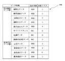
周辺機器(手術装置20)のデータ群及び患者7の生体情報(バイタルサインデータ)のデータ群は、図5に示すように、RAM53にテーブルデータ100として格納されており、変更があると所定時間の経過毎に更新される。これらデータ群の各データには更新フラグが設けられており、データに変更があると更新フラグが立てられ(フラグ=1)、この更新フラグを参照することでデータの更新処理を実行するようになっている。 The data group of the peripheral device (surgical device 20) and the data group of the vital information (vital sign data) of the
また、テーブルデータ100には、データ群の各データのうちデータが更新された際に支援室6に送信すべきデータが予め送信対象データとして登録されている。 In the
したがって、コントローラ24では、所定時間毎のデータ更新状態を更新フラグにより認識し、送信対象データの更新フラグが1となっているデータを支援室6に送信する処理を行う。 Therefore, the
詳細には、周辺機器(手術装置20)のデータ群が更新されたと判断すると、ステップS4において周辺機器(手術装置20)のデータ群の更新されたデータの更新フラグを1とし、ステップS5に進み、ステップS3で周辺機器(手術装置20)のデータ群が更新されていない判断するとそのままステップS5に進む。 Specifically, if it is determined that the data group of the peripheral device (surgical device 20) has been updated, the updated data update flag of the data group of the peripheral device (surgical device 20) is set to 1 in step S4, and the process proceeds to step S5. If it is determined in step S3 that the data group of the peripheral device (surgical device 20) has not been updated, the process proceeds directly to step S5.
ステップS5においては、患者7の生体情報(バイタルサインデータ)のデータ群が更新されたかどうか判断する。生体情報(バイタルサインデータ)のデータ群が更新されたと判断すると、ステップS6において生体情報(バイタルサインデータ)のデータ群の更新されたデータの更新フラグを1とし、ステップS7に進み、ステップS5で生体情報(バイタルサインデータ)のデータ群が更新されていない判断するとそのままステップS7に進む。 In step S5, it is determined whether the data group of the biological information (vital sign data) of the
そして、ステップS7において更新されたデータの表示を変更し、ステップS8において送信対象データのうち更新フラグが1のデータがあるかどうか判断し、更新フラグが1の送信対象データがある場合には、ステップS9においてIPアドレス記憶部59より支援室6の信号伝送装置28のIPアドレスを読み出し、該IPアドレスに更新フラグが1の送信対象データにIDリーダ26により得た患者データを付加し信号伝送I/F部56を介して送信し、ステップS10において手技が終了するまでステップS2からの処理を繰り返す。 Then, the display of the updated data is changed in step S7. In step S8, it is determined whether there is data with the
このように本実施例では、手術室に設けられている手術装置のデータ群及び生体情報(バイタルサインデータ)のデータ群をコントローラ24が一元的に管理すると共に、これらデータ群のうち予め登録した送信対象データに変化が生じた際に、該送信対象データのみをIPアドレス記憶部59に格納されているIPアドレス先の支援室6に伝送するので、インターネット通信回線4のトラフィックを最適に保持した状態で、支援室6に手術の支援に必要な情報を提供できるので、支援室6からの支援を効率的に行うことが可能となる。 As described above, in this embodiment, the
なお、上記実施例では、タイマによる所定時間間隔でデータ群の更新状態を監視し、更新がなされたときに送信対象データを送信するとしたが、これに限らず、各手術装置20からデータ更新のイベントが発生した場合に、割り込み処理を行い更新状態を監視し、更新がなされたときに送信対象データを送信するようにしてもよい。 In the above-described embodiment, the update state of the data group is monitored at predetermined time intervals by the timer, and the transmission target data is transmitted when the update is performed. However, the present invention is not limited to this. When an event occurs, interrupt processing may be performed to monitor the update state, and transmission target data may be transmitted when an update is made.
また、本実施例では、上述したように患者モニタリング装置50、光源装置17、VTR23、CCU21及び手術装置20が一般的なそれぞれのシリアル通信によりコントローラ24とデータの送受を行うとしたが、これに限らず、患者モニタリング装置50、光源装置17、VTR23、CCU21及び手術装置20とコントローラ24とをイーサネット(R)(Ethernet(R))により接続することで、図6に示すようにハブ200を介して患者モニタリング装置50、CCU21及び手術装置20とコントローラ24とを接続することが可能であり、コントローラ24に1つのイーサネット(R)コネクタを設けるだけで各装置とのデータの送受が可能となり、手術室5内の接続環境を大幅に改善することは可能となる。 In the present embodiment, as described above, the
[付記]
(付記項1) 前記複数の医療装置は、共通のネットワークプロトコルにて前記制御装置に接続される
ことを特徴とする請求項1に記載の手術支援システム。[Appendix]
(Additional Item 1) The surgical support system according to
(付記項2) 共通のネットワークプロトコルはイーサネット(R)プロトコルである
ことを特徴とする付記項1に記載の手術支援システム。(Additional Item 2) The surgery support system according to
(付記項3) 前記通信回線のプロトコルはインターネットプロトコルである
ことを特徴とする請求項1、付記項1または付記項2のいずれかに記載の手術支援システム。(Additional Item 3) The surgical operation support system according to any one of
本発明は、上述した実施例に限定されるものではなく、本発明の要旨を変えない範囲において、種々の変更、改変等が可能である。 The present invention is not limited to the above-described embodiments, and various changes and modifications can be made without departing from the scope of the present invention.
1…遠隔支援内視鏡システム
2…手術装置部
3…遠隔支援装置部
4…公衆回線
5…手術室
6…遠隔支援装置室
7…患者
8…手術具本体
9…内視鏡
10…内視鏡撮像装置
12…挿入部
14…CCD
15…テレビカメラ
17…光源装置
20…手術装置
21…CCU
22…第1モニタ
24…(第1の)コントローラ
25…タッチパネル
26…IDリーダ
27…(第1の)信号伝送装置
28…(第2の)信号伝送装置
29…第2モニタ
31…第3モニタ
32…(第2の)コントローラ
33…第4モニタ
34…入力装置
50…患者モニタリング装置
51…ROM
52…CPU
53…RAM
54…タッチパネルI/F部
55…モニタリングI/F部
56…信号伝送I/F部
57…IDリーダI/F部
58…手術装置I/F部
59…IPアドレス記憶部
100…テーブルデータ
200…ハブ
代理人 弁理士 伊藤 進DESCRIPTION OF
15 ... TV camera 17 ...
DESCRIPTION OF
52 ... CPU
53 ... RAM
54 ... Touch panel I / F unit 55 ... Monitoring I /
Claims (2)
Translated fromJapanese前記制御装置と通信回線を介してデータの送受を行う支援装置と
を備え、
前記制御装置は、
前記複数の医療装置の制御データのうち所定のデータを送信対象データとして記憶するする送信対象データ記憶手段と、
前記支援装置の前記通信回線上のアドレスを記憶するアドレス記憶手段と
前記制御データを監視し前記送信対象データに変化が生じた際に、前記アドレス記憶手段より前記アドレスを読み出し、変化が生じた前記送信対象データを前記支援装置に前記通信回線を介して送信するデータ送信制御手段と
を備えたことを特徴とする手術支援システム。A plurality of medical devices and a control device for controlling the medical devices;
A support device that transmits and receives data via a communication line with the control device,
The control device includes:
Transmission target data storage means for storing predetermined data among the control data of the plurality of medical devices as transmission target data;
Address storage means for storing the address on the communication line of the support device and when the control data is monitored and a change occurs in the transmission target data, the address is read from the address storage means, and the change has occurred A surgery support system comprising: data transmission control means for transmitting transmission target data to the support device via the communication line.
前記複数の医療装置の制御データのうち所定のデータを送信対象データとして前記制御装置の記憶部に記憶するする送信対象データ記憶ステップと、
前記支援装置の前記通信回線上のアドレスを前記記憶部に記憶するアドレス記憶ステップと
前記制御データを監視し前記送信対象データに変化が生じた際に、前記記憶部より前記アドレスを読み出し、変化が生じた前記送信対象データを前記制御装置から前記支援装置に前記通信回線を介して送信するデータ送信制御ステップと
を備えたことを特徴とする手術支援システムの手術支援方法。In a surgical support method of a surgical support system, comprising a plurality of medical devices, a control device that controls the medical devices, and a support device that transmits and receives data via the control device and a communication line,
A transmission target data storage step of storing predetermined data among the control data of the plurality of medical devices as transmission target data in a storage unit of the control device;
An address storing step of storing the address on the communication line of the support device in the storage unit; and when the control data is monitored and a change occurs in the transmission target data, the address is read from the storage unit, And a data transmission control step of transmitting the generated transmission target data from the control device to the support device via the communication line.
Priority Applications (2)
| Application Number | Priority Date | Filing Date | Title |
|---|---|---|---|
| JP2003351227AJP2005111085A (en) | 2003-10-09 | 2003-10-09 | Operation supporting system |
| US10/961,987US20050149001A1 (en) | 2003-10-09 | 2004-10-08 | Operation support system and support method of operation support system |
Applications Claiming Priority (1)
| Application Number | Priority Date | Filing Date | Title |
|---|---|---|---|
| JP2003351227AJP2005111085A (en) | 2003-10-09 | 2003-10-09 | Operation supporting system |
Publications (1)
| Publication Number | Publication Date |
|---|---|
| JP2005111085Atrue JP2005111085A (en) | 2005-04-28 |
Family
ID=34542556
Family Applications (1)
| Application Number | Title | Priority Date | Filing Date |
|---|---|---|---|
| JP2003351227APendingJP2005111085A (en) | 2003-10-09 | 2003-10-09 | Operation supporting system |
Country Status (2)
| Country | Link |
|---|---|
| US (1) | US20050149001A1 (en) |
| JP (1) | JP2005111085A (en) |
Cited By (6)
| Publication number | Priority date | Publication date | Assignee | Title |
|---|---|---|---|---|
| JP2009527268A (en)* | 2006-02-20 | 2009-07-30 | コーニンクレッカ フィリップス エレクトロニクス エヌ ヴィ | A method for extracting a graphic description of a display object specializing in a region to an external display unit in a patient monitor system |
| JP2013215258A (en)* | 2012-04-05 | 2013-10-24 | Kenta Miki | Support system |
| JP2016202940A (en)* | 2016-07-15 | 2016-12-08 | 健太 三木 | Support system |
| CN109498174A (en)* | 2018-12-26 | 2019-03-22 | 南通市第人民医院 | A kind of vascular surgery monitor and alarm system |
| JP2021037330A (en)* | 2020-11-24 | 2021-03-11 | シスメックス株式会社 | Medical robotic system, data analysis device, and monitoring method for medical robot |
| US11813733B2 (en) | 2015-12-11 | 2023-11-14 | Sysmex Corporation | Medical robot system, data analysis apparatus, and medical-robot monitoring method |
Families Citing this family (152)
| Publication number | Priority date | Publication date | Assignee | Title |
|---|---|---|---|---|
| JP2005533607A (en) | 2002-07-25 | 2005-11-10 | シャーウッド・サービシーズ・アクチェンゲゼルシャフト | Electrosurgical pencil with drag detection |
| US7244257B2 (en)* | 2002-11-05 | 2007-07-17 | Sherwood Services Ag | Electrosurgical pencil having a single button variable control |
| AU2004212990B2 (en) | 2003-02-20 | 2009-12-10 | Covidien Ag | Motion detector for controlling electrosurgical output |
| US7241294B2 (en) | 2003-11-19 | 2007-07-10 | Sherwood Services Ag | Pistol grip electrosurgical pencil with manual aspirator/irrigator and methods of using the same |
| US7503917B2 (en)* | 2003-11-20 | 2009-03-17 | Covidien Ag | Electrosurgical pencil with improved controls |
| US7879033B2 (en)* | 2003-11-20 | 2011-02-01 | Covidien Ag | Electrosurgical pencil with advanced ES controls |
| US7156844B2 (en) | 2003-11-20 | 2007-01-02 | Sherwood Services Ag | Electrosurgical pencil with improved controls |
| US7156842B2 (en) | 2003-11-20 | 2007-01-02 | Sherwood Services Ag | Electrosurgical pencil with improved controls |
| US7500974B2 (en) | 2005-06-28 | 2009-03-10 | Covidien Ag | Electrode with rotatably deployable sheath |
| US8401869B2 (en)* | 2005-08-24 | 2013-03-19 | Image Stream Medical, Inc. | Streaming video network system |
| US7828794B2 (en) | 2005-08-25 | 2010-11-09 | Covidien Ag | Handheld electrosurgical apparatus for controlling operating room equipment |
| EP1762198A1 (en)* | 2005-09-13 | 2007-03-14 | Sherwood Services AG | Handheld electrosurgical apparatus for controlling operating room equipment |
| US20070260240A1 (en) | 2006-05-05 | 2007-11-08 | Sherwood Services Ag | Soft tissue RF transection and resection device |
| US8506565B2 (en) | 2007-08-23 | 2013-08-13 | Covidien Lp | Electrosurgical device with LED adapter |
| US8235987B2 (en) | 2007-12-05 | 2012-08-07 | Tyco Healthcare Group Lp | Thermal penetration and arc length controllable electrosurgical pencil |
| US8663218B2 (en) | 2008-03-31 | 2014-03-04 | Covidien Lp | Electrosurgical pencil including improved controls |
| US8636733B2 (en) | 2008-03-31 | 2014-01-28 | Covidien Lp | Electrosurgical pencil including improved controls |
| US8597292B2 (en) | 2008-03-31 | 2013-12-03 | Covidien Lp | Electrosurgical pencil including improved controls |
| US8162937B2 (en) | 2008-06-27 | 2012-04-24 | Tyco Healthcare Group Lp | High volume fluid seal for electrosurgical handpiece |
| US8231620B2 (en) | 2009-02-10 | 2012-07-31 | Tyco Healthcare Group Lp | Extension cutting blade |
| DE102010039289A1 (en)* | 2010-08-12 | 2012-02-16 | Leica Microsystems (Schweiz) Ag | microscope system |
| US9959785B2 (en) | 2010-08-24 | 2018-05-01 | Vti Medical, Inc. | Apparatus and method for laparoscopic skills training |
| US11871901B2 (en) | 2012-05-20 | 2024-01-16 | Cilag Gmbh International | Method for situational awareness for surgical network or surgical network connected device capable of adjusting function based on a sensed situation or usage |
| US11504192B2 (en) | 2014-10-30 | 2022-11-22 | Cilag Gmbh International | Method of hub communication with surgical instrument systems |
| US11311342B2 (en) | 2017-10-30 | 2022-04-26 | Cilag Gmbh International | Method for communicating with surgical instrument systems |
| US11229436B2 (en) | 2017-10-30 | 2022-01-25 | Cilag Gmbh International | Surgical system comprising a surgical tool and a surgical hub |
| US11911045B2 (en) | 2017-10-30 | 2024-02-27 | Cllag GmbH International | Method for operating a powered articulating multi-clip applier |
| US11510741B2 (en) | 2017-10-30 | 2022-11-29 | Cilag Gmbh International | Method for producing a surgical instrument comprising a smart electrical system |
| US11291510B2 (en) | 2017-10-30 | 2022-04-05 | Cilag Gmbh International | Method of hub communication with surgical instrument systems |
| US11317919B2 (en) | 2017-10-30 | 2022-05-03 | Cilag Gmbh International | Clip applier comprising a clip crimping system |
| US11026687B2 (en) | 2017-10-30 | 2021-06-08 | Cilag Gmbh International | Clip applier comprising clip advancing systems |
| US11925373B2 (en) | 2017-10-30 | 2024-03-12 | Cilag Gmbh International | Surgical suturing instrument comprising a non-circular needle |
| US11801098B2 (en) | 2017-10-30 | 2023-10-31 | Cilag Gmbh International | Method of hub communication with surgical instrument systems |
| US11564756B2 (en) | 2017-10-30 | 2023-01-31 | Cilag Gmbh International | Method of hub communication with surgical instrument systems |
| US11132462B2 (en) | 2017-12-28 | 2021-09-28 | Cilag Gmbh International | Data stripping method to interrogate patient records and create anonymized record |
| US11096693B2 (en) | 2017-12-28 | 2021-08-24 | Cilag Gmbh International | Adjustment of staple height of at least one row of staples based on the sensed tissue thickness or force in closing |
| US11696760B2 (en) | 2017-12-28 | 2023-07-11 | Cilag Gmbh International | Safety systems for smart powered surgical stapling |
| US11179175B2 (en) | 2017-12-28 | 2021-11-23 | Cilag Gmbh International | Controlling an ultrasonic surgical instrument according to tissue location |
| US11304763B2 (en) | 2017-12-28 | 2022-04-19 | Cilag Gmbh International | Image capturing of the areas outside the abdomen to improve placement and control of a surgical device in use |
| US11464535B2 (en) | 2017-12-28 | 2022-10-11 | Cilag Gmbh International | Detection of end effector emersion in liquid |
| US10943454B2 (en) | 2017-12-28 | 2021-03-09 | Ethicon Llc | Detection and escalation of security responses of surgical instruments to increasing severity threats |
| US11234756B2 (en) | 2017-12-28 | 2022-02-01 | Cilag Gmbh International | Powered surgical tool with predefined adjustable control algorithm for controlling end effector parameter |
| US11202570B2 (en) | 2017-12-28 | 2021-12-21 | Cilag Gmbh International | Communication hub and storage device for storing parameters and status of a surgical device to be shared with cloud based analytics systems |
| US11056244B2 (en) | 2017-12-28 | 2021-07-06 | Cilag Gmbh International | Automated data scaling, alignment, and organizing based on predefined parameters within surgical networks |
| US11076921B2 (en) | 2017-12-28 | 2021-08-03 | Cilag Gmbh International | Adaptive control program updates for surgical hubs |
| US10966791B2 (en) | 2017-12-28 | 2021-04-06 | Ethicon Llc | Cloud-based medical analytics for medical facility segmented individualization of instrument function |
| US11659023B2 (en) | 2017-12-28 | 2023-05-23 | Cilag Gmbh International | Method of hub communication |
| US10755813B2 (en) | 2017-12-28 | 2020-08-25 | Ethicon Llc | Communication of smoke evacuation system parameters to hub or cloud in smoke evacuation module for interactive surgical platform |
| US11786245B2 (en) | 2017-12-28 | 2023-10-17 | Cilag Gmbh International | Surgical systems with prioritized data transmission capabilities |
| US11571234B2 (en) | 2017-12-28 | 2023-02-07 | Cilag Gmbh International | Temperature control of ultrasonic end effector and control system therefor |
| US11291495B2 (en) | 2017-12-28 | 2022-04-05 | Cilag Gmbh International | Interruption of energy due to inadvertent capacitive coupling |
| US11786251B2 (en) | 2017-12-28 | 2023-10-17 | Cilag Gmbh International | Method for adaptive control schemes for surgical network control and interaction |
| US20190201142A1 (en) | 2017-12-28 | 2019-07-04 | Ethicon Llc | Automatic tool adjustments for robot-assisted surgical platforms |
| US11051876B2 (en) | 2017-12-28 | 2021-07-06 | Cilag Gmbh International | Surgical evacuation flow paths |
| US11464559B2 (en) | 2017-12-28 | 2022-10-11 | Cilag Gmbh International | Estimating state of ultrasonic end effector and control system therefor |
| US20190206569A1 (en) | 2017-12-28 | 2019-07-04 | Ethicon Llc | Method of cloud based data analytics for use with the hub |
| US11903601B2 (en) | 2017-12-28 | 2024-02-20 | Cilag Gmbh International | Surgical instrument comprising a plurality of drive systems |
| US11529187B2 (en) | 2017-12-28 | 2022-12-20 | Cilag Gmbh International | Surgical evacuation sensor arrangements |
| US11602393B2 (en) | 2017-12-28 | 2023-03-14 | Cilag Gmbh International | Surgical evacuation sensing and generator control |
| US12127729B2 (en) | 2017-12-28 | 2024-10-29 | Cilag Gmbh International | Method for smoke evacuation for surgical hub |
| US11832899B2 (en) | 2017-12-28 | 2023-12-05 | Cilag Gmbh International | Surgical systems with autonomously adjustable control programs |
| US11069012B2 (en) | 2017-12-28 | 2021-07-20 | Cilag Gmbh International | Interactive surgical systems with condition handling of devices and data capabilities |
| US11540855B2 (en) | 2017-12-28 | 2023-01-03 | Cilag Gmbh International | Controlling activation of an ultrasonic surgical instrument according to the presence of tissue |
| US12396806B2 (en) | 2017-12-28 | 2025-08-26 | Cilag Gmbh International | Adjustment of a surgical device function based on situational awareness |
| US11273001B2 (en) | 2017-12-28 | 2022-03-15 | Cilag Gmbh International | Surgical hub and modular device response adjustment based on situational awareness |
| US11832840B2 (en) | 2017-12-28 | 2023-12-05 | Cilag Gmbh International | Surgical instrument having a flexible circuit |
| US10849697B2 (en) | 2017-12-28 | 2020-12-01 | Ethicon Llc | Cloud interface for coupled surgical devices |
| US11666331B2 (en) | 2017-12-28 | 2023-06-06 | Cilag Gmbh International | Systems for detecting proximity of surgical end effector to cancerous tissue |
| US10892995B2 (en) | 2017-12-28 | 2021-01-12 | Ethicon Llc | Surgical network determination of prioritization of communication, interaction, or processing based on system or device needs |
| US11304745B2 (en) | 2017-12-28 | 2022-04-19 | Cilag Gmbh International | Surgical evacuation sensing and display |
| US12376855B2 (en) | 2017-12-28 | 2025-08-05 | Cilag Gmbh International | Safety systems for smart powered surgical stapling |
| US11896322B2 (en) | 2017-12-28 | 2024-02-13 | Cilag Gmbh International | Sensing the patient position and contact utilizing the mono-polar return pad electrode to provide situational awareness to the hub |
| US11308075B2 (en) | 2017-12-28 | 2022-04-19 | Cilag Gmbh International | Surgical network, instrument, and cloud responses based on validation of received dataset and authentication of its source and integrity |
| US11013563B2 (en) | 2017-12-28 | 2021-05-25 | Ethicon Llc | Drive arrangements for robot-assisted surgical platforms |
| US11026751B2 (en) | 2017-12-28 | 2021-06-08 | Cilag Gmbh International | Display of alignment of staple cartridge to prior linear staple line |
| US12062442B2 (en) | 2017-12-28 | 2024-08-13 | Cilag Gmbh International | Method for operating surgical instrument systems |
| US11419630B2 (en) | 2017-12-28 | 2022-08-23 | Cilag Gmbh International | Surgical system distributed processing |
| US11266468B2 (en) | 2017-12-28 | 2022-03-08 | Cilag Gmbh International | Cooperative utilization of data derived from secondary sources by intelligent surgical hubs |
| US12096916B2 (en) | 2017-12-28 | 2024-09-24 | Cilag Gmbh International | Method of sensing particulate from smoke evacuated from a patient, adjusting the pump speed based on the sensed information, and communicating the functional parameters of the system to the hub |
| US11424027B2 (en) | 2017-12-28 | 2022-08-23 | Cilag Gmbh International | Method for operating surgical instrument systems |
| US10987178B2 (en) | 2017-12-28 | 2021-04-27 | Ethicon Llc | Surgical hub control arrangements |
| US11937769B2 (en) | 2017-12-28 | 2024-03-26 | Cilag Gmbh International | Method of hub communication, processing, storage and display |
| US11559308B2 (en) | 2017-12-28 | 2023-01-24 | Cilag Gmbh International | Method for smart energy device infrastructure |
| US11304699B2 (en) | 2017-12-28 | 2022-04-19 | Cilag Gmbh International | Method for adaptive control schemes for surgical network control and interaction |
| US11998193B2 (en) | 2017-12-28 | 2024-06-04 | Cilag Gmbh International | Method for usage of the shroud as an aspect of sensing or controlling a powered surgical device, and a control algorithm to adjust its default operation |
| US11818052B2 (en) | 2017-12-28 | 2023-11-14 | Cilag Gmbh International | Surgical network determination of prioritization of communication, interaction, or processing based on system or device needs |
| US11389164B2 (en) | 2017-12-28 | 2022-07-19 | Cilag Gmbh International | Method of using reinforced flexible circuits with multiple sensors to optimize performance of radio frequency devices |
| US11559307B2 (en) | 2017-12-28 | 2023-01-24 | Cilag Gmbh International | Method of robotic hub communication, detection, and control |
| US11744604B2 (en) | 2017-12-28 | 2023-09-05 | Cilag Gmbh International | Surgical instrument with a hardware-only control circuit |
| US11147607B2 (en) | 2017-12-28 | 2021-10-19 | Cilag Gmbh International | Bipolar combination device that automatically adjusts pressure based on energy modality |
| US10932872B2 (en) | 2017-12-28 | 2021-03-02 | Ethicon Llc | Cloud-based medical analytics for linking of local usage trends with the resource acquisition behaviors of larger data set |
| US11284936B2 (en) | 2017-12-28 | 2022-03-29 | Cilag Gmbh International | Surgical instrument having a flexible electrode |
| US11576677B2 (en) | 2017-12-28 | 2023-02-14 | Cilag Gmbh International | Method of hub communication, processing, display, and cloud analytics |
| US10892899B2 (en) | 2017-12-28 | 2021-01-12 | Ethicon Llc | Self describing data packets generated at an issuing instrument |
| US11100631B2 (en) | 2017-12-28 | 2021-08-24 | Cilag Gmbh International | Use of laser light and red-green-blue coloration to determine properties of back scattered light |
| US20190201112A1 (en) | 2017-12-28 | 2019-07-04 | Ethicon Llc | Computer implemented interactive surgical systems |
| US10918310B2 (en) | 2018-01-03 | 2021-02-16 | Biosense Webster (Israel) Ltd. | Fast anatomical mapping (FAM) using volume filling |
| US11633237B2 (en) | 2017-12-28 | 2023-04-25 | Cilag Gmbh International | Usage and technique analysis of surgeon / staff performance against a baseline to optimize device utilization and performance for both current and future procedures |
| US11896443B2 (en) | 2017-12-28 | 2024-02-13 | Cilag Gmbh International | Control of a surgical system through a surgical barrier |
| US11423007B2 (en) | 2017-12-28 | 2022-08-23 | Cilag Gmbh International | Adjustment of device control programs based on stratified contextual data in addition to the data |
| US11589888B2 (en) | 2017-12-28 | 2023-02-28 | Cilag Gmbh International | Method for controlling smart energy devices |
| US11324557B2 (en) | 2017-12-28 | 2022-05-10 | Cilag Gmbh International | Surgical instrument with a sensing array |
| US11376002B2 (en) | 2017-12-28 | 2022-07-05 | Cilag Gmbh International | Surgical instrument cartridge sensor assemblies |
| US11678881B2 (en) | 2017-12-28 | 2023-06-20 | Cilag Gmbh International | Spatial awareness of surgical hubs in operating rooms |
| US20190201090A1 (en) | 2017-12-28 | 2019-07-04 | Ethicon Llc | Capacitive coupled return path pad with separable array elements |
| US11278281B2 (en) | 2017-12-28 | 2022-03-22 | Cilag Gmbh International | Interactive surgical system |
| US11612444B2 (en) | 2017-12-28 | 2023-03-28 | Cilag Gmbh International | Adjustment of a surgical device function based on situational awareness |
| WO2019133144A1 (en) | 2017-12-28 | 2019-07-04 | Ethicon Llc | Detection and escalation of security responses of surgical instruments to increasing severity threats |
| US10944728B2 (en) | 2017-12-28 | 2021-03-09 | Ethicon Llc | Interactive surgical systems with encrypted communication capabilities |
| US11253315B2 (en) | 2017-12-28 | 2022-02-22 | Cilag Gmbh International | Increasing radio frequency to create pad-less monopolar loop |
| US11166772B2 (en) | 2017-12-28 | 2021-11-09 | Cilag Gmbh International | Surgical hub coordination of control and communication of operating room devices |
| US10898622B2 (en) | 2017-12-28 | 2021-01-26 | Ethicon Llc | Surgical evacuation system with a communication circuit for communication between a filter and a smoke evacuation device |
| US11446052B2 (en) | 2017-12-28 | 2022-09-20 | Cilag Gmbh International | Variation of radio frequency and ultrasonic power level in cooperation with varying clamp arm pressure to achieve predefined heat flux or power applied to tissue |
| US11257589B2 (en) | 2017-12-28 | 2022-02-22 | Cilag Gmbh International | Real-time analysis of comprehensive cost of all instrumentation used in surgery utilizing data fluidity to track instruments through stocking and in-house processes |
| US11304720B2 (en) | 2017-12-28 | 2022-04-19 | Cilag Gmbh International | Activation of energy devices |
| US11109866B2 (en) | 2017-12-28 | 2021-09-07 | Cilag Gmbh International | Method for circular stapler control algorithm adjustment based on situational awareness |
| US11969142B2 (en) | 2017-12-28 | 2024-04-30 | Cilag Gmbh International | Method of compressing tissue within a stapling device and simultaneously displaying the location of the tissue within the jaws |
| US11432885B2 (en) | 2017-12-28 | 2022-09-06 | Cilag Gmbh International | Sensing arrangements for robot-assisted surgical platforms |
| US11311306B2 (en) | 2017-12-28 | 2022-04-26 | Cilag Gmbh International | Surgical systems for detecting end effector tissue distribution irregularities |
| US11364075B2 (en) | 2017-12-28 | 2022-06-21 | Cilag Gmbh International | Radio frequency energy device for delivering combined electrical signals |
| US20190201039A1 (en) | 2017-12-28 | 2019-07-04 | Ethicon Llc | Situational awareness of electrosurgical systems |
| US11317937B2 (en) | 2018-03-08 | 2022-05-03 | Cilag Gmbh International | Determining the state of an ultrasonic end effector |
| US11160605B2 (en) | 2017-12-28 | 2021-11-02 | Cilag Gmbh International | Surgical evacuation sensing and motor control |
| US10758310B2 (en) | 2017-12-28 | 2020-09-01 | Ethicon Llc | Wireless pairing of a surgical device with another device within a sterile surgical field based on the usage and situational awareness of devices |
| US11864728B2 (en) | 2017-12-28 | 2024-01-09 | Cilag Gmbh International | Characterization of tissue irregularities through the use of mono-chromatic light refractivity |
| US11857152B2 (en)* | 2017-12-28 | 2024-01-02 | Cilag Gmbh International | Surgical hub spatial awareness to determine devices in operating theater |
| US11179208B2 (en) | 2017-12-28 | 2021-11-23 | Cilag Gmbh International | Cloud-based medical analytics for security and authentication trends and reactive measures |
| US11410259B2 (en) | 2017-12-28 | 2022-08-09 | Cilag Gmbh International | Adaptive control program updates for surgical devices |
| US11969216B2 (en) | 2017-12-28 | 2024-04-30 | Cilag Gmbh International | Surgical network recommendations from real time analysis of procedure variables against a baseline highlighting differences from the optimal solution |
| US11419667B2 (en) | 2017-12-28 | 2022-08-23 | Cilag Gmbh International | Ultrasonic energy device which varies pressure applied by clamp arm to provide threshold control pressure at a cut progression location |
| US11986233B2 (en) | 2018-03-08 | 2024-05-21 | Cilag Gmbh International | Adjustment of complex impedance to compensate for lost power in an articulating ultrasonic device |
| US11259830B2 (en) | 2018-03-08 | 2022-03-01 | Cilag Gmbh International | Methods for controlling temperature in ultrasonic device |
| US12303159B2 (en) | 2018-03-08 | 2025-05-20 | Cilag Gmbh International | Methods for estimating and controlling state of ultrasonic end effector |
| US11534196B2 (en) | 2018-03-08 | 2022-12-27 | Cilag Gmbh International | Using spectroscopy to determine device use state in combo instrument |
| US10973520B2 (en) | 2018-03-28 | 2021-04-13 | Ethicon Llc | Surgical staple cartridge with firing member driven camming assembly that has an onboard tissue cutting feature |
| US11278280B2 (en) | 2018-03-28 | 2022-03-22 | Cilag Gmbh International | Surgical instrument comprising a jaw closure lockout |
| US11219453B2 (en) | 2018-03-28 | 2022-01-11 | Cilag Gmbh International | Surgical stapling devices with cartridge compatible closure and firing lockout arrangements |
| US11207067B2 (en) | 2018-03-28 | 2021-12-28 | Cilag Gmbh International | Surgical stapling device with separate rotary driven closure and firing systems and firing member that engages both jaws while firing |
| US11090047B2 (en) | 2018-03-28 | 2021-08-17 | Cilag Gmbh International | Surgical instrument comprising an adaptive control system |
| US11589865B2 (en) | 2018-03-28 | 2023-02-28 | Cilag Gmbh International | Methods for controlling a powered surgical stapler that has separate rotary closure and firing systems |
| US11471156B2 (en) | 2018-03-28 | 2022-10-18 | Cilag Gmbh International | Surgical stapling devices with improved rotary driven closure systems |
| US11213294B2 (en) | 2018-03-28 | 2022-01-04 | Cilag Gmbh International | Surgical instrument comprising co-operating lockout features |
| US11096688B2 (en) | 2018-03-28 | 2021-08-24 | Cilag Gmbh International | Rotary driven firing members with different anvil and channel engagement features |
| US11464511B2 (en) | 2019-02-19 | 2022-10-11 | Cilag Gmbh International | Surgical staple cartridges with movable authentication key arrangements |
| US11331100B2 (en) | 2019-02-19 | 2022-05-17 | Cilag Gmbh International | Staple cartridge retainer system with authentication keys |
| US11369377B2 (en) | 2019-02-19 | 2022-06-28 | Cilag Gmbh International | Surgical stapling assembly with cartridge based retainer configured to unlock a firing lockout |
| US11357503B2 (en) | 2019-02-19 | 2022-06-14 | Cilag Gmbh International | Staple cartridge retainers with frangible retention features and methods of using same |
| US11317915B2 (en) | 2019-02-19 | 2022-05-03 | Cilag Gmbh International | Universal cartridge based key feature that unlocks multiple lockout arrangements in different surgical staplers |
| USD952144S1 (en) | 2019-06-25 | 2022-05-17 | Cilag Gmbh International | Surgical staple cartridge retainer with firing system authentication key |
| USD950728S1 (en) | 2019-06-25 | 2022-05-03 | Cilag Gmbh International | Surgical staple cartridge |
| USD964564S1 (en) | 2019-06-25 | 2022-09-20 | Cilag Gmbh International | Surgical staple cartridge retainer with a closure system authentication key |
| US11564732B2 (en) | 2019-12-05 | 2023-01-31 | Covidien Lp | Tensioning mechanism for bipolar pencil |
Family Cites Families (18)
| Publication number | Priority date | Publication date | Assignee | Title |
|---|---|---|---|---|
| US5627584A (en)* | 1991-01-17 | 1997-05-06 | Olympus Optical Co., Ltd. | Endoscope system with centralized control of associated peripheral equipment |
| US6023632A (en)* | 1997-07-16 | 2000-02-08 | Wilk; Peter J. | Ultrasonic medical system and associated method |
| US5871446A (en)* | 1992-01-10 | 1999-02-16 | Wilk; Peter J. | Ultrasonic medical system and associated method |
| US5685821A (en)* | 1992-10-19 | 1997-11-11 | Arthrotek | Method and apparatus for performing endoscopic surgical procedures |
| US5419312A (en)* | 1993-04-20 | 1995-05-30 | Wildflower Communications, Inc. | Multi-function endoscope apparatus |
| US6496099B2 (en)* | 1996-06-24 | 2002-12-17 | Computer Motion, Inc. | General purpose distributed operating room control system |
| US6319201B1 (en)* | 1997-10-15 | 2001-11-20 | Peter J. Wilk | Imaging device and associated method |
| US6106463A (en)* | 1998-04-20 | 2000-08-22 | Wilk; Peter J. | Medical imaging device and associated method including flexible display |
| US6424996B1 (en)* | 1998-11-25 | 2002-07-23 | Nexsys Electronics, Inc. | Medical network system and method for transfer of information |
| US6602185B1 (en)* | 1999-02-18 | 2003-08-05 | Olympus Optical Co., Ltd. | Remote surgery support system |
| US6791601B1 (en)* | 1999-11-11 | 2004-09-14 | Stryker Corporation | Multi-function image and video capture device for use in an endoscopic camera system |
| US20030060808A1 (en)* | 2000-10-04 | 2003-03-27 | Wilk Peter J. | Telemedical method and system |
| JP2002238919A (en)* | 2001-02-20 | 2002-08-27 | Olympus Optical Co Ltd | Control apparatus for medical care system and medical care system |
| US20030093503A1 (en)* | 2001-09-05 | 2003-05-15 | Olympus Optical Co., Ltd. | System for controling medical instruments |
| US6728599B2 (en)* | 2001-09-07 | 2004-04-27 | Computer Motion, Inc. | Modularity system for computer assisted surgery |
| US6824539B2 (en)* | 2002-08-02 | 2004-11-30 | Storz Endoskop Produktions Gmbh | Touchscreen controlling medical equipment from multiple manufacturers |
| US20040030367A1 (en)* | 2002-08-09 | 2004-02-12 | Olympus Optical Co., Ltd. | Medical control device, control method for medical control device, medical system device and control system |
| JP4236436B2 (en)* | 2002-09-19 | 2009-03-11 | オリンパス株式会社 | Endoscopic surgical system |
- 2003
- 2003-10-09JPJP2003351227Apatent/JP2005111085A/enactivePending
- 2004
- 2004-10-08USUS10/961,987patent/US20050149001A1/ennot_activeAbandoned
Cited By (7)
| Publication number | Priority date | Publication date | Assignee | Title |
|---|---|---|---|---|
| JP2009527268A (en)* | 2006-02-20 | 2009-07-30 | コーニンクレッカ フィリップス エレクトロニクス エヌ ヴィ | A method for extracting a graphic description of a display object specializing in a region to an external display unit in a patient monitor system |
| JP2013215258A (en)* | 2012-04-05 | 2013-10-24 | Kenta Miki | Support system |
| US11813733B2 (en) | 2015-12-11 | 2023-11-14 | Sysmex Corporation | Medical robot system, data analysis apparatus, and medical-robot monitoring method |
| JP2016202940A (en)* | 2016-07-15 | 2016-12-08 | 健太 三木 | Support system |
| CN109498174A (en)* | 2018-12-26 | 2019-03-22 | 南通市第人民医院 | A kind of vascular surgery monitor and alarm system |
| JP2021037330A (en)* | 2020-11-24 | 2021-03-11 | シスメックス株式会社 | Medical robotic system, data analysis device, and monitoring method for medical robot |
| JP7043570B2 (en) | 2020-11-24 | 2022-03-29 | シスメックス株式会社 | Medical robot system, data analysis device, and monitoring method for medical robot |
Also Published As
| Publication number | Publication date |
|---|---|
| US20050149001A1 (en) | 2005-07-07 |
Similar Documents
| Publication | Publication Date | Title |
|---|---|---|
| JP2005111085A (en) | Operation supporting system | |
| US11123150B2 (en) | Information processing apparatus, assistance system, and information processing method | |
| JP7067467B2 (en) | Information processing equipment for medical use, information processing method, information processing system for medical use | |
| US7485115B2 (en) | Remote operation support system and method | |
| JP7200939B2 (en) | Surgical system, control method, surgical equipment, and program | |
| JP2010082040A (en) | Endoscope system | |
| JP2005169009A (en) | Endoscope system and endoscope | |
| JPWO2018168261A1 (en) | CONTROL DEVICE, CONTROL METHOD, AND PROGRAM | |
| JP4880398B2 (en) | Endoscopic diagnosis system | |
| US11883120B2 (en) | Medical observation system, medical signal processing device, and medical signal processing device driving method | |
| CN110913787B (en) | Operation support system, information processing method, and information processing device | |
| JP2018075218A (en) | Medical support arm and medical system | |
| CN113613542A (en) | Disposable device with integrated vision capabilities | |
| JP2000271147A (en) | Remote surgery support system | |
| WO2017145606A1 (en) | Image processing device, image processing method, and endoscope system | |
| WO2019181242A1 (en) | Endoscope and arm system | |
| JP2002233535A (en) | Endoscopic operation system | |
| JP4445598B2 (en) | Endoscope visual field control system | |
| JP2000245738A (en) | Remote operation supporting system | |
| JP2005143918A (en) | Remote operation support system | |
| JP7544033B2 (en) | Medical system, information processing device, and information processing method | |
| JP2005342400A (en) | Endoscope apparatus and endoscope system | |
| JP2001238205A (en) | Endoscope system | |
| JP2005123900A (en) | Medical image transmission system | |
| JP2007080094A (en) | Application startup management system |
Legal Events
| Date | Code | Title | Description |
|---|---|---|---|
| A621 | Written request for application examination | Free format text:JAPANESE INTERMEDIATE CODE: A621 Effective date:20060824 | |
| A131 | Notification of reasons for refusal | Free format text:JAPANESE INTERMEDIATE CODE: A131 Effective date:20090714 | |
| A02 | Decision of refusal | Free format text:JAPANESE INTERMEDIATE CODE: A02 Effective date:20091110 |