JP2005110412A - Power supply system - Google Patents
Power supply systemDownload PDFInfo
- Publication number
- JP2005110412A JP2005110412AJP2003340772AJP2003340772AJP2005110412AJP 2005110412 AJP2005110412 AJP 2005110412AJP 2003340772 AJP2003340772 AJP 2003340772AJP 2003340772 AJP2003340772 AJP 2003340772AJP 2005110412 AJP2005110412 AJP 2005110412A
- Authority
- JP
- Japan
- Prior art keywords
- power
- power transmission
- transmission device
- supply system
- power supply
- Prior art date
- Legal status (The legal status is an assumption and is not a legal conclusion. Google has not performed a legal analysis and makes no representation as to the accuracy of the status listed.)
- Pending
Links
Images


Landscapes
- Charge And Discharge Circuits For Batteries Or The Like (AREA)
Abstract
Translated fromJapaneseDescription
Translated fromJapanese本発明は、電子機器へ電力を供給する電力供給システムに関するものであり、特に、携帯電話やノートパソコン、デジタルカメラ、電子玩具等のモバイル可能な電子機器に電力を供給する電力供給システムに関するものである。 The present invention relates to a power supply system that supplies power to an electronic device, and more particularly to a power supply system that supplies power to a mobile electronic device such as a mobile phone, a notebook computer, a digital camera, or an electronic toy. is there.
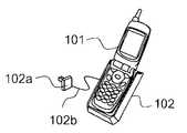
従来のモバイル可能な電子機器への電力供給システムの例を図13〜図15に示す。先ず、図13は、従来の電力供給システムを搭載した携帯電話機とその携帯電話機の端子接触型専用充電器(ACアダプタ)の外観を示す外観図である。図13において、101は携帯電話機を示し、102は携帯電話機101に内蔵された蓄電池を充電するための端子接触型専用充電器(ACアダプタ)のホルダーを示す。ACアダプタのホルダー102には(ACプラグ一体型の)ACアダプタ102aとコード102bが取り付けられており、壁面等に設けられたコンセントに(ACプラグ一体型の)ACプラグ102aを差し込むことにより商用電源(AC100V)がACアダプタ102aに供給される。そして、ACアダプタ102aは、供給されたAC100Vを携帯電話機101の蓄電池の充電に使用するDC電圧に変換し、コード102b及びACアダプタのホルダー102及び携帯電話機101の受電電極と接触する送電電極を介して、このDC電圧で携帯電話機101の蓄電池を充電する。また、このDC電圧は直接、携帯電話機101の駆動電源とすることもできる。 Examples of conventional power supply systems for mobile electronic devices are shown in FIGS. First, FIG. 13 is an external view showing the external appearance of a mobile phone equipped with a conventional power supply system and a terminal contact type charger (AC adapter) of the mobile phone. In FIG. 13,
次に、図14は、従来の他の電力供給システムを搭載したノートパソコンとそのノートパソコンの専用充電器(ACアダプタ)の外観を示す外観図である。図14において、103はノートパソコンを示し、104はノートパソコン103に内蔵された蓄電池を充電するための専用充電器(ACアダプタ)を示す。ACアダプタ104にはACプラグ104aとコード104b、104cが取り付けられており、壁面等に設けられたコンセントにACプラグ104aを差し込むことによりコード104bを介して商用電源(AC100V)がACアダプタ104に供給される。そして、ACアダプタ104は、供給されたAC100Vをノートパソコン103の蓄電池の充電に使用するDC電圧に変換し、コード104cを介して、このDC電圧をノートパソコン103に供給し、内蔵された蓄電池を充電する。また、このDC電圧は直接、ノートパソコン103の駆動電源とすることもできる。 Next, FIG. 14 is an external view showing the external appearance of a notebook computer equipped with another conventional power supply system and a dedicated charger (AC adapter) for the notebook computer. In FIG. 14,
次に、図15は、従来の他の電力供給システムを搭載したシェーバーとそのシェーバーの非接触型専用充電器(ACアダプタ)の外観を示す外観図である。図15において、105はシェーバーを示し、106はシェーバー105に内蔵された蓄電池を充電するための非接触型専用充電器(ACアダプタ)を示す。ACアダプタ106にはACプラグ106aとコード106bが取り付けられており、壁面等に設けられたコンセントにACプラグ106aを差し込むことによりコード106bを介して商用電源(AC100V)がACアダプタ106に供給される。ACアダプタ106は、供給されたAC100Vを一旦、直流電圧に変換した後にスイッチングし、磁気結合を利用した非接触電力供給方法によってシェーバー105の蓄電池に、充電に使用するDC電圧を供給する。また、このDC電圧は直接、シェーバー105の駆動電源とすることもできる。 Next, FIG. 15 is an external view showing the external appearance of a shaver equipped with another conventional power supply system and a non-contact dedicated charger (AC adapter) of the shaver. In FIG. 15,
また、本体の底部に2次側コイルを配設すると共に、充電器の本体載置部下に1次側コイルを配設し、本体を充電器の本体載置部に載置すると、本体載置部下に配設した1次側コイルと本体の底部に配設した2次側コイルが磁気結合され、本体内の蓄電池が充電される非接触充電装置において、本体のハウジングが、2次側コイルを縦断する面で分割された複数のハウジング部品を組み合わせて構成され、複数のハウジング部品の内、1つのハウジング部品にはその外周壁に連続して底壁が形成され、該底壁の内面に2次側コイルが配設され、且つ該底壁の外面は充電の際、充電器の本体載置部との接触面となる非接触充電装置がある(例えば、特許文献1参照)。
しかしながら、図13〜図15に示すように、携帯電話機101、ノートパソコン103、シェーバー105の各電子機器の充電には各電子機器ごとに専用のACアダプタが必要であり、それ以外のACアダプタを使用することはできない、即ち、ACアダプタ同士に互換性が無い。特に、携帯電話機の場合、機種別/メーカー別に専用のACアダプタが使用されており、機器間の互換性が無く、不便であった。そのため、家庭内には多くのACアダプタがあふれており、それらACアダプタやACアダプタを商用電源に接続するためのコードが邪魔になるという問題があった。 However, as shown in FIGS. 13 to 15, the charging of each electronic device such as the
また、パソコンラックのような棚に機器を配置している場合、機器の配置換えをおこなう際には、機器とACアダプタ両方の配置を換える必要があり、面倒であった。更に、掃除ロボットやおもちゃロボット等は、専用の充電アダプタにより充電を行なわなければならず、充電のたびにロボットをACアダプタに接続しなければならなかった。また、移動先や移動中の公共施設内でも、持っている電子機器の専用のACアダプタを持ち歩かねばならず、このことがモバイル可能な電子機器の可搬性を大きく損ねていた。例えば、車での移動中は、ダッシュボードやコンソールボックス等に充電アダプタを取り付けて、携帯電話の充電を行なっていたが、アダプタやコードが邪魔であり、視界を遮る場合もあった。 Further, when devices are arranged on a shelf such as a personal computer rack, it is necessary to change the arrangement of both the device and the AC adapter when changing the arrangement of the devices, which is troublesome. Furthermore, cleaning robots, toy robots, and the like have to be charged by a dedicated charging adapter, and the robot must be connected to the AC adapter each time it is charged. In addition, it is necessary to carry a dedicated AC adapter for the electronic device in the destination or in a moving public facility, which greatly impairs the portability of the mobile electronic device. For example, while moving in a car, a charging adapter is attached to a dashboard, console box, or the like to charge a mobile phone. However, the adapter or cord is in the way and sometimes obstructs the field of view.
また、特許文献1に記載の従来技術では、ハウジングの底部で接合したハウジング部品間に段差が生じるような心配がなく、1次側コイルと2次側コイル間の距離を一定に保つことができるので、本体の電子機器に安定した充電電流を供給することはできるが、非接触充電装置が充電できる電子機器の種類は、予め定められた1種類のみであり、複数の種類の電子機器を充電することはできないという問題があった。 Moreover, in the prior art described in
本発明は、上記の点に鑑み、1つの送電装置で異なる種類の電子機器に電力を供給することができるとともに省スペースを可能にした電力供給システムを提供することを目的とする。 An object of the present invention is to provide a power supply system that can supply power to different types of electronic devices with a single power transmission device and can save space.
上記目的を達成するために本発明は、商用電源が与えられる送電装置から受電機器へ、電気的に非接触な方式で電力を供給する電力供給システムにおいて、前記送電装置が器具に組み込まれていることを特徴とするものである。このようにすると、省スペースを可能にした電力供給システムが実現できる。 In order to achieve the above object, according to the present invention, in a power supply system that supplies power in an electrically non-contact manner from a power transmission device to which a commercial power source is supplied to a power receiving device, the power transmission device is incorporated in an instrument. It is characterized by this. If it does in this way, the electric power supply system which enabled space saving is realizable.
また、本発明は、商用電源が与えられる送電装置から受電機器へ、該受電機器の電力に応じて送電電力を調整して電気的に非接触な方式で電力を供給する電力供給システムにおいて、前記送電装置が器具に組み込まれていることを特徴とするものである。このようにすると、1つの送電装置で異なる種類の受電機器に電力を供給することができるとともに省スペースを可能にした電力供給システムが実現できる。 Further, the present invention provides a power supply system that adjusts the transmission power according to the power of the power receiving device and supplies the power in an electrically non-contact manner from the power transmission device to which the commercial power is supplied to the power receiving device. The power transmission device is incorporated in the appliance. In this way, it is possible to realize a power supply system that can supply power to different types of power receiving devices with one power transmission device and can save space.
また、本発明は、1次側コイルと、商用電源を整流平滑して得た直流電圧をスイッチングしたパルス電圧を前記1次側コイルに与える1次側回路とを有する送電装置と、前記1次側コイルと磁気結合される2次側コイルと、該2次側コイルに誘起される誘起電圧を整流平滑する2次側回路とを有する受電機器とから成り、前記受電機器の電力に応じて送電電力を調整する電力調整手段を備えた電力供給システムにおいて、前記送電装置が器具に組み込まれていることを特徴とするものである。このようにすると、1つの送電装置で異なる種類の受電機器に電力を供給することができるとともに省スペースを可能にした電力供給システムが実現できる。 In addition, the present invention provides a power transmission device including a primary side coil, and a primary side circuit that supplies a pulse voltage obtained by switching a DC voltage obtained by rectifying and smoothing a commercial power source to the primary side coil, and the primary side A power receiving device having a secondary side coil magnetically coupled to the side coil and a secondary side circuit that rectifies and smoothes an induced voltage induced in the secondary side coil, and transmits power according to the power of the power receiving device. In the power supply system provided with the power adjusting means for adjusting the power, the power transmission device is incorporated in an appliance. In this way, it is possible to realize a power supply system that can supply power to different types of power receiving devices with one power transmission device and can save space.
また、例えば、前記器具が机の天板であると、ACアダプタや充電器を置くスペースが不要になるとともに、商用電力を供給するための電源コードが邪魔になることがなく、机上のスペースが有効活用できる。 Further, for example, if the appliance is a desk top, a space for placing an AC adapter or a charger is not required, and a power cord for supplying commercial power does not get in the way, and there is no space on the desk. Can be used effectively.
また、例えば、前記器具が棚板であると、ACアダプタや充電器の収納スペースが不要になるとともに、商用電力が供給される部屋の壁などに設けられたACコンセントから棚までの電源コードを複数の棚板に組み込まれた複数の送電装置で共用にできるため、電源コードを少なくすることができる。また、送電装置を利用しない場合は棚の収納スペースを全て活用することができる。 Further, for example, if the appliance is a shelf board, a storage space for an AC adapter or a charger is not necessary, and a power cord from an AC outlet to a shelf provided on a wall of a room to which commercial power is supplied is used. Since it can be shared by a plurality of power transmission devices incorporated in a plurality of shelves, power cords can be reduced. In addition, when the power transmission device is not used, the entire storage space of the shelf can be utilized.
また、例えば、前記器具が鍵のかかる収納スペースを構成する底板であると、この収納スペースは鍵を掛けることができるため、公共の場でもこの収納スペース内に載置した受電機器を充電しているときに、その場に待機する必要がなく便利である。また、公共の場でも、送電装置が盗難されたり、壊されることが少なくなるという利点もある。 In addition, for example, if the appliance is a bottom plate constituting a lockable storage space, the storage space can be locked, so that the power receiving device placed in the storage space can be charged even in public places. Convenient because you don't have to wait when you are. In addition, there is an advantage that the power transmission device is less likely to be stolen or broken even in public places.
また、例えば、前記器具が前記受電機器を保持するホルダであると、ホルダタイプであるので、移動中も位置ずれが発生しにくく、安定して受電機器への電力供給が可能である。また、受電機器に電力供給しながらこの受電機器を使用することにより、移動中であっても電池残量を気にせず、長時間使用することができるといった利点がある。また、送電装置は組み込まれているため、公共の場でも勝手に持ち帰られるというようなことが少なくなる。 Further, for example, when the instrument is a holder that holds the power receiving device, since it is a holder type, positional displacement is unlikely to occur during movement, and power can be stably supplied to the power receiving device. Further, by using the power receiving device while supplying power to the power receiving device, there is an advantage that it can be used for a long time without worrying about the remaining amount of the battery even during movement. Moreover, since the power transmission device is incorporated, it is less likely that the power transmission device is taken home without permission.
また、例えば、前記器具が車のダッシュボード及び/またはコンソールボックスであると、ダッシュボードやコンソールボックスに組み込まれているため、ACアダプタや充電器を置くスペースが不要になるとともに、ACアダプタや充電器やそれに接続されるコードのように視界を遮るものが無くなり、運転上安全である。また、受電機器を電力供給しながらこの受電機器を使用することにより、移動中の車内であっても電池残量を気にせず、長時間使用することができるといった利点がある。 Further, for example, if the appliance is a dashboard and / or console box of a car, it is incorporated in the dashboard or console box, so that a space for placing an AC adapter or a charger becomes unnecessary, and an AC adapter or charging There is no need to obstruct the field of view like a container or a cord connected to it, which is safe for driving. Further, by using the power receiving device while supplying power to the power receiving device, there is an advantage that it can be used for a long time without worrying about the remaining battery level even in a moving vehicle.
また、例えば、前記器具が表面シートであると、ACアダプタや充電器を置くスペースが不要になるとともに、表面シート内に送電装置が組み込まれているため、充電を行なわないときは表面シート全体を利用することが出来る。 Further, for example, when the appliance is a top sheet, a space for placing an AC adapter or a charger is not necessary, and a power transmission device is incorporated in the top sheet. It can be used.
また、例えば、前記送電装置が前記器具の側面や壁に組み込まれていると、前記器具の側面や壁の表面にコードを這わす必要がなく、また、ACアダプタや充電器を置くスペースが不要になるとともに、受電機器を床に置くスペースも必要としないという利点がある。 For example, when the power transmission device is incorporated in the side surface or wall of the appliance, there is no need to fold the cord on the side surface or wall surface of the appliance, and there is no need for a space for placing an AC adapter or a charger. In addition, there is an advantage that a space for placing the power receiving device on the floor is not required.
また、例えば、前記送電装置が床または床に敷く敷物に組み込まれていると、掃除ロボットのように床または床に敷いた敷物上を走行する受電機器に電力供給できるので、長時間動きつづけさせることが可能である。また、送電装置は床または床に敷く敷物の中に組み込まれているため、床または床に敷く敷物に凹凸部が発生することがなく、床または床に敷いた敷物上を走行する受電機器がスムーズに動くことが出来る。 In addition, for example, when the power transmission device is incorporated in a floor or a rug laid on the floor, power can be supplied to a power receiving device that runs on the floor or a rug laid on the floor like a cleaning robot, so that it can continue to move for a long time. It is possible. In addition, since the power transmission device is built into the floor or a floor covering, there is no unevenness on the floor or the floor covering, and power receiving equipment that runs on the floor or a floor covering is not It can move smoothly.
本発明によれば、1次側コイルと、商用電源を整流平滑して得た直流電圧をスイッチングしたパルス電圧を前記1次側コイルに与える1次側回路とを有する送電装置と、前記1次側コイルと磁気結合される2次側コイルと、該2次側コイルに誘起される誘起電圧を整流平滑する2次側回路とを有する受電機器とから成り、前記受電機器の電力に応じて送電電力を調整する電力調整手段を備えた電力供給システムにおいて、前記送電装置が器具に組み込まれているので、1つの送電装置で異なる種類の電子機器に電力を供給することができるとともに省スペースを可能にした電力供給システムが実現できる。 According to the present invention, a power transmission device including a primary side coil and a primary side circuit that supplies a pulse voltage obtained by switching a DC voltage obtained by rectifying and smoothing a commercial power source to the primary side coil, and the primary A power receiving device having a secondary side coil magnetically coupled to the side coil and a secondary side circuit that rectifies and smoothes an induced voltage induced in the secondary side coil, and transmits power according to the power of the power receiving device. In the power supply system provided with the power adjusting means for adjusting the power, since the power transmission device is incorporated in the appliance, it is possible to supply power to different types of electronic devices with one power transmission device and to save space An electric power supply system can be realized.
以下に、本発明の実施形態を図面を参照して説明する。図1は、本発明の第1実施形態の電力供給システムを搭載した送電装置と受電機器の外観を示す外観図である。図1において、1は電力を供給する送電装置であり、(a)は受電機器が携帯電話機2である場合を示し、(b)は受電機器がノートパソコン3である場合を示している。送電装置1はACプラグ1aとコード1bを備えており、壁面等に設けられたコンセントにACプラグ1aを差し込むことによりコード1bを介して商用電源(AC100V)が送電装置1に供給される。送電装置1は、供給されたAC100Vを一旦、直流電圧に変換した後、スイッチングし、磁気結合を利用した非接触電力供給方法によって受電機器である携帯電話機2やノートパソコン3の蓄電池に、充電に使用するDC電圧を供給する。また、このDC電圧は直接、携帯電話機2やノートパソコン3の駆動電源とすることもできる。 Embodiments of the present invention will be described below with reference to the drawings. FIG. 1 is an external view showing an external appearance of a power transmission device and a power receiving device equipped with the power supply system of the first embodiment of the present invention. In FIG. 1,
また、送電装置1は、送電装置1の上に載置された受電機器を認識して、受電機器に応じてその受電機器に必要な電力を送電する機能を有しているため、1つの送電装置1により、携帯電話機2やノートパソコン3のように充電に必要な電力が異なる電子機器であっても充電することが可能である。また、図示していないが、デジタルカメラ、ビデオカメラ、PDA等の蓄電池を有する電子機器であれば、同様に充電することが可能である。また、送電装置1はAC100Vの入力状態や受電機器への電力供給状態等を示す発光ダイオード(表示手段)LED1、LED2(以下、単にLED1、LED2と呼称する)を備えている。このLED1、LED2の機能や動作等については後述する。 Further, the
次に、図2を参照して非接触伝送方式の原理を説明する。図2は、図1に示す送電装置1と携帯電話機2の内部の概略構成を説明するための図であり、(a)は送電装置1と携帯電話機2の全体を示し、(b)はコイル部分を拡大して示している。図2において、図1と同一の部分には同一の符号を付し、その説明を省略する。図2(a)に示すように、送電装置1は1次側回路10と1次側コイル11を備えており、携帯電話機2は2次側コイル12と2次側回路13と充電制御回路14を備えている。 Next, the principle of the non-contact transmission method will be described with reference to FIG. FIG. 2 is a diagram for explaining a schematic configuration inside the
1次側回路10はACプラグ1a、コード1bを介して供給されたAC100Vを全波整流し平滑して、一旦、直流電圧にした後、その直流電圧をスイッチングしたパルス電圧を1次側コイル11に与える。1次側コイル11と2次側コイル12とは、図2(b)に示すように、1次側コア(フェライト)15と2次側コア(フェライト)16とが磁気結合されたトランスを形成しており、1次側コイル11にスイッチングされたパルス電圧が与えられると、2次側コイル12には磁気結合により1次側コイル11と2次側コイル12との巻数比に応じた電圧が誘起される。そして、その誘起された誘起電圧を2次側回路13で整流し平滑した直流電圧を充電制御回路14に与え、充電制御回路14はその与えられたDC電圧で蓄電池を充電する。このようにして、送電装置1から携帯電話機2への非接触電力供給が行われる。 The
また、1次側回路10と2次側回路13との間では、電力供給に関しての情報等の信号が、上述した非接触伝送方式で伝送される。この信号伝送は以下のような目的のために行われる。第1は、送電装置1の上に金属などが置かれた状態で電力を送電すると、その金属が渦電流により発熱する問題があるため、受電可能な機器が置かれたことを認識するためである。第2は、受電機器に応じた必要な電力を送電するために、送電装置1側がコイル及び回路の切り替えを行う必要があるため、受電機器の電力量情報を送電装置1側が認識するためである。第3は、受電機器が満充電になったら送電を止める必要があるため(省エネのため)、満充電になったかどうかを送電装置1側が認識するためである。 Moreover, between the
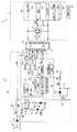
図3は、図1、図2に示す送電装置と携帯電話機の電気的構成を示すブロック図である。図3において、図1、図2と同一の部分には同一の符号を付し、その説明を省略する。図3において、ACプラグ1aからコード1bを介して外部から商用電源(AC100V)が供給され、この供給されたAC100Vは1次側回路10内の整流回路21で全波整流された後、コイルL1とコンデンサC1とから成る平滑回路で平滑されて直流電圧に変換される。そして、その直流電圧をスイッチング回路22によりスイッチングしたパルス電圧がトランジスタTR11、TR12、TR13を介して1次側コイル11に与えられる。 FIG. 3 is a block diagram illustrating an electrical configuration of the power transmission device and the mobile phone illustrated in FIGS. 1 and 2. 3, the same parts as those in FIGS. 1 and 2 are denoted by the same reference numerals, and the description thereof is omitted. In FIG. 3, commercial power (AC100V) is supplied from the
トランジスタTR11、TR12、TR13はいずれもNPN型のトランジスタであり、いずれもコレクタがスイッチング回路22の出力端に接続されている。また、トランジスタTR11のエミッタは1次側コイル11の一端に接続され、1次側コイル11の他端はグランドに接続されている。また、1次側コイル11はグランドに接続されたコイル端から遠い方から順に、即ち、巻数の多い方から順にタップa,b,cを有しており、トランジスタTR12のエミッタはタップaに接続され、トランジスタTR13のエミッタはタップbに接続されている。また、タップcは、1次側回路10の送電制御を行う送電制御IC(電力調整手段)24の復調回路36と搬送波発振回路37に接続されている。また、トランジスタTR11、TR12、TR13のベースはそれぞれ送電制御IC24の電力切替回路32に接続されている。この送電制御IC24は、LED表示回路31、電力切替回路32、送電可否判定回路33、電力量判定回路34、満充電判定回路35、復調回路36、搬送波発振回路37から構成されたICであり、送電装置1の小型薄型化のためにICチップ化されている。それぞれの回路の機能や動作については後述する。尚、トランジスタTR11、TR12、TR13はMOSFET等の他のスイッチング素子であっても良いし、セレクタスイッチ等でも良い。 The transistors TR11, TR12, and TR13 are all NPN type transistors, and the collectors are all connected to the output terminal of the switching
また、スイッチング回路22によりスイッチングされたパルス電圧はトランス23にも与えられ、トランス23によって所定の電圧に変換された後、整流回路25で整流され、コイルL2とコンデンサC2とから成る平滑回路で平滑されて直流電圧に変換される。この直流電圧は1次側回路10の制御用の電源Vccとして、1次側回路10の各制御回路等に与えられる。 The pulse voltage switched by the switching
また、電源VccにNPN型のトランジスタTR1、TR2のコレクタが接続され、トランジスタTR1のエミッタは電流制限用の抵抗R1を介してLED1のアノードに接続され、LED1のカソードはグランドに接続されている。一方、トランジスタTR2のエミッタは電流制限用の抵抗R2を介してLED2のアノードに接続され、LED2のカソードはグランドに接続されている。また、トランジスタTR1、TR2の各ベースは送電制御IC24のLED表示回路31に接続されている。このような構成によりLED表示回路31がトランジスタTR1をオンさせるとLED1が発光し、トランジスタTR2をオンさせるとLED2が発光する。但し、図示しない点灯制御回路等により、LED1はLED表示回路31からの信号に応じて赤色、黄色、緑色、紫色、橙色に発光する機能を有しており、LED2は同様に赤色、緑色に発光する機能を有している。尚、トランジスタTR1、TR2はMOSFET等の他のスイッチング素子であっても良い。 Further, the collectors of NPN transistors TR1 and TR2 are connected to the power source Vcc, the emitter of the transistor TR1 is connected to the anode of the LED1 via the current limiting resistor R1, and the cathode of the LED1 is connected to the ground. On the other hand, the emitter of the transistor TR2 is connected to the anode of the
次に、携帯電話機2側の説明を行う。2次側コイル12の両端に平滑用のコンデンサC4と整流回路41が接続されており、2次側コイル12に誘起された誘起電圧は整流回路41で全波整流された後、コイルL3とコンデンサC3とから成る平滑回路で平滑されて直流電圧に変換される。そして、この直流電圧が2次側回路13の受電制御を行う受電制御IC(電力調整手段)42のパワーオンリセット回路44、電圧クランプ回路46、レギュレータ47に与えられる。 Next, the
パワーオンリセット回路44は、後述する1次側回路10から伝送される搬送波が変換された直流電圧を検知することにより送電装置1から情報信号の要求があったと判断して受電制御IC42をリセットして情報信号の送信を開始させるための回路である。また、電圧クランプ回路46は、変換された直流電圧を所定の電圧にクランプして各回路が電圧破壊されることを防止するための回路であり、レギュレータ47はこの変換された直流電圧を充電に使用される所定の電圧に変換して充電制御回路14に供給するための回路である。また、受電制御IC42は、更に、2次側コイル12に接続されたクロック抽出回路43と変調回路45を備えており、1次側コイル11及び2次側コイル12を介して伝送される信号の信号処理を行う。尚、この受電制御IC42は、携帯電話機2の小型薄型化のためにICチップ化されている。 The power-on
次に、このような構成の送電装置1と携帯電話機2の電力供給動作を図4を参照して説明する。図4は、送電装置1の電力供給動作を示すフローチャートである。送電装置1はAC100Vが供給されたときに動作を開始する。先ず、AC100Vが入力されると、送電制御IC24に制御用の電源Vccが供給されるので、LED表示回路31はLED1を赤色に点灯させ、LED2は消灯させる(ステップS1)。そして、搬送波発振回路37は、所定の搬送波を一定間隔で出力し(ステップS2)、受電機器が送電装置1の上に載置されているかどうかを判断する(ステップS3)。この受電機器が載置されているかどうかを判断する方法を以下に説明する。 Next, the power supply operation of the
搬送波発振回路37から出力された搬送波は1次側コイル11のタップcに与えられ、送電装置1の上に携帯電話機2が載置されている場合は、磁気結合された2次側コイル12に伝送される。この2次側コイル12に伝送された搬送波は整流回路41、コイルL3、コンデンサC3により整流、平滑されて直流電圧に変換される。そして、この搬送波が変換された直流電圧をパワーオンリセット回路44で検出して、搬送波が伝送されてきたことを認識する。そして、2次側コイル12に接続されたクロック抽出回路43は、その搬送波から変調に必要となるクロック信号を抽出し、変調回路45は、携帯電話機2の情報である“受電機器であることを示すコード”、“消費電力の情報”、“満充電の情報”に基づいて搬送波を変調した変調波を2次側コイル12に与える。このときの変調方式は、搬送波を周期的に強度変調し、信号の位相変化情報で0/1情報を表現する位相変調方式を用いている。このように、送電装置1から伝送された搬送波から変調に必要なクロック信号を抽出するので、受電機器である携帯電話機2内に発信回路を有する必要がなく、更に、クロック抽出回路43、変調回路45の駆動電力は搬送波により供給される電力を用いるので、受電機器である携帯電話機2内に電源も必要なく、回路を簡素化できる。 The carrier wave output from the carrier
変調回路45から2次側コイル12に与えられた変調波は、磁気結合された1次側コイル11に伝送される。そして、1次側コイル11のタップcに接続された復調回路36は、伝送された変調波を受信して復調し、復調された情報信号に含まれる“受電機器であることを示すコード”、“消費電力の情報”、“満充電の情報”を送電可否判定回路33、電力量判定回路34、満充電判定回路35に与える。ここで、送電可否判定回路33は、“受電機器であることを示すコード”に基づいて、受電機器が送電装置1の上に載置されているかどうかを判断する(ステップS3)。所定の“受電機器であることを示すコード”が受信できていれば、受電機器が送電装置1の上に載置されていると認識し、次に、受電機器が送電装置1の上に正しく載置されているかどうかを判断する(ステップS4)。一方、所定の“受電機器であることを示すコード”が受信できていなければ、受電機器が送電装置1の上に載置されていないと判断して再び搬送波を出力する(ステップS2)。 The modulated wave supplied from the
次に、受電機器が送電装置1の上に正しく載置されているかどうかの判断であるが、受電機器が送電装置1の上に正しく載置されているという意味は、非接触電力供給において、送電側のコイルと受電側のコイルとが電力の伝達効率が高い位置に配置されているかどうか、換言すれば、図2に示した送電装置1の1次側コア15と受電機器である携帯電話機2の2次側コア16の磁気結合が高い結合度になる位置に送電装置1と携帯電話機2とが配置されているかどうかという意味である。 Next, it is a determination of whether or not the power receiving device is correctly placed on the
そして、送電装置1と携帯電話機2との位置のずれ量が大きくなるほど電力の伝達効率は悪くなるので、電力の伝達効率が著しく低い場合は、送電装置1から送電を行っても携帯電話機2は受電できないということになり、送電を行う意味がなくなるので、送電装置1と携帯電話機2との位置のずれ量が所定のずれ量を超えたかどうかを判定し(ステップS4)、超えている場合は送電装置1からの送電は行わないこととし、警告表示としてLED1を橙色に点灯させ、LED2は消灯させる(ステップS5)。また、このとき、警告音を発生させるようにしても良い。 And as the amount of positional deviation between the
一方、送電装置1と携帯電話機2との位置のずれ量が所定のずれ量を超えていない場合は、送電する電力量を判定する処理に移行する(ステップS6)。この判定処理は、復調回路36で復調される情報信号に含まれる“消費電力の情報”に基づいて、電力量判定回路34で行われ、“消費電力の情報”に基づいて携帯電話機2の電力を認識し、その電力に応じて送電出力を大、中、小の3段階に調整する。電力量判定回路34からの判定結果はLED表示回路31と電力切替回路32に伝えられ、大、中、小の判定結果に応じて、以下のような処理が行われる。 On the other hand, when the amount of position shift between the
先ず、判定結果が小の場合、LED表示回路31は、小電力送電を行うという意味で、LED1を黄色に点灯させ、LED2を赤色で点滅させる(ステップS7)。また、電力切替回路32はトランジスタTR11をオンする。トランジスタTR11がオンすると、スイッチング回路22からのパルス電圧が1次側コイル11の巻線全体に印加され、送電が開始される(ステップS8)。次に、判定結果が中の場合、LED表示回路31は、中電力送電を行うという意味で、LED1を緑色に点灯させ、LED2を赤色で点滅させる(ステップS9)。また、電力切替回路32はトランジスタTR12をオンする。トランジスタTR12がオンすると、スイッチング回路22からのパルス電圧が1次側コイル11のタップaに印加され、送電が開始される(ステップS10)。また、判定結果が大の場合、LED表示回路31は、大電力送電を行うという意味で、LED1を紫色に点灯させ、LED2を赤色で点滅させる(ステップS11)。また、電力切替回路32はトランジスタTR13をオンする。トランジスタTR13がオンすると、スイッチング回路22からのパルス電圧が1次側コイル11のタップbに印加され、送電が開始される(ステップS12)。 First, when the determination result is small, the LED display circuit 31 turns on the
トランジスタTR11、TR12、TR13を切り替えることにより、スイッチング回路からのパルス電圧が印加される位置が1次側コイル11の巻線上で変化する。即ち、実際に有効となる1次側コイルの巻数が変化するので、1次側コイル11:2次側コイル12の巻数比が変化する。このようにして、受電機器の電力に応じた電力を送電することを可能としている。尚、本実施例は、大、中、小の3段階に切り替えているが、切り換え数を更に増やしても良い。 By switching the transistors TR11, TR12, and TR13, the position to which the pulse voltage from the switching circuit is applied changes on the winding of the
送電が開始された後も、定期的に搬送波を送信し(ステップS13)、その搬送波に対して返送される変調波に含まれる情報に基づいて、先ず、受電機器である携帯電話機2が送電装置1の上から取り除かれていないかどうかを確認する(ステップS14)。この確認は、ステップS3と同様に、送電可否判定回路33が“受電機器であることを示すコード”に基づいて、受電機器が送電装置1の上に載置されているかどうかを判断する。そして、所定の“受電機器であることを示すコード”が受信できていなければ、受電機器が送電装置1の上から取り除かれたと判断し、電力切替回路32がトランジスタTR11、TR12、TR13の全てをオフして電力出力を停止する(ステップS15)。 Even after power transmission is started, a carrier wave is periodically transmitted (step S13). Based on information included in a modulated wave returned to the carrier wave, first, the
一方、所定の“受電機器であることを示すコード”が受信できていれば、受電機器が送電装置1の上に載置されていると認識し、次に、受電機器が送電装置1の上に正しく載置されているかどうかを判断する(ステップS16)。この判断は、ステップS4と同様に、送電装置1と携帯電話機2との位置のずれ量が所定のずれ量を超えたかどうかの判定により行われる。そして、このずれ量が所定のずれ量を超えている場合は、送電装置1からの送電は行わないこととし、ステップS5と同様に、警告表示としてLED1を橙色に点灯させ、LED2は消灯させる(ステップS17)。また、このとき、警告音を発生させるようにしても良い。 On the other hand, if a predetermined “code indicating that the device is a power receiving device” is received, it is recognized that the power receiving device is placed on the
一方、送電装置1と携帯電話機2との位置のずれ量が所定のずれ量を超えていない場合は、次に、携帯電話機2が満充電であるかどうかを判定する処理に移行する(ステップS18)。この判定処理は、満充電判定回路35が、復調回路36で復調される情報信号に含まれる“満充電の情報”に基づいて、携帯電話機2が満充電の状態かどうかを判定して行われる。そして、満充電である場合は、電力切替回路32がトランジスタTR11、TR12、TR13の全てをオフして電力出力を停止し(ステップS19)、受電機器が満充電状態のために送電を停止しているという意味で、LED1を赤色で点灯、LED2を緑色で点灯させ(ステップS20)、搬送波を出力して受電機器の状態の確認を継続する(ステップS13)。一方、満充電でない場合は、送電を行いながら受電機器の状態の確認を継続する(ステップS13)。以上のようにして、送電装置1から携帯電話機2への非接触電力供給が行われる。 On the other hand, when the amount of positional deviation between the
図5は、本発明の第2実施形態の電力供給システムの外観を示す外観図である。図5に示す電力供給システムは、図1〜図3に示す送電装置1が机の天板(器具)に組み込まれていることを特徴としており、その例をいくつか示している。図5において、(a)は天板51aに送電装置1が組み込まれている書斎などに置かれる書斎机51の外観を示し、(b)は天板51aの送電装置1が組み込まれている箇所51bの部分を拡大して示している。送電装置1は、図5(b)に示すように、天板51aの表面に突出することがないように、天板51aに内部に組み込まれている。また、(c)は天板52aに送電装置1が組み込まれている会議室などに置かれる会議机52の外観を示している。そして、52bは送電装置1が組み込まれている箇所を示しており、図5(b)と同様の形態で送電装置1が組み込まれている。また、(d)は天板53aに送電装置1が組み込まれている飲食店などに置かれる飲食店の机53の外観を示している。そして、53bは送電装置1が組み込まれている箇所を示しており、図5(b)と同様の形態で送電装置1が組み込まれている。また、(e)は天板54aに送電装置1が組み込まれている電車の机54の外観を示している。そして、54bは送電装置1が組み込まれている箇所を示しており、図5(b)と同様の形態で送電装置1が組み込まれている。尚、組み込まれた送電装置1への商用電源(AC100V)供給のためのACプラグやコードは図示されていないが、図5に示す各机及びその天板の内部に設置された電源コード等を介して、組み込まれた送電装置1に商用電源が供給されるようになっている。 FIG. 5 is an external view showing the external appearance of the power supply system according to the second embodiment of the present invention. The power supply system shown in FIG. 5 is characterized in that the
また、図5において、2は図1〜図3に示す携帯電話機、3は図1に示すノートパソコンを示し、各種の机の天板に組み込まれた送電装置1は、送電装置1が組み込まれた箇所に携帯電話機2またはノートパソコン3が置かれると、上述のようにして、置かれた携帯電話機2またはノートパソコン3の必要な電力を検知し、これらに送電する電力を調整して給電する。即ち、1つの送電装置1で、送電装置1が組み込まれた机の上に置かれた種々の受電機器に電力を供給することを可能としている。また、このように机の天板に送電装置1を組み込むことにより、ACアダプタや充電器を置くスペースが不要になるとともに、商用電力を供給するための電源コードが邪魔になることがなく、机上のスペースが有効活用できるというメリットがある。 In FIG. 5, 2 is the mobile phone shown in FIGS. 1 to 3, 3 is the notebook computer shown in FIG. 1, and the
さらに、図5(e)に示すように、移動車両の中のテーブルや、図5(c)、図5(d)に示すように、移動先(店や会議室)の施設内のテーブルに、この送電装置1が組み込まれていれば、機器専用のACアダプタや充電器を持ち運ぶ必要が無くなり、どこでも充電可能となり、機器の電池残量を気にせず機器を使用することが可能となる。また、送電装置1は種々の機器の充電が可能であるため、携帯電話機やノートパソコンに限らず、PDA、デジタルカメラ、ビデオカメラ等の充電池を有する機器であれば同様に充電することが可能である。尚、図示したもの以外に、飛行機、船等の乗り物の机、学習机、ホットスポットに設置された机、ホテルの各部屋に設置された机にも同様に送電装置1を組み込むことが可能である。 Furthermore, as shown in FIG. 5 (e), the table in the moving vehicle or the table in the facility of the destination (store or conference room) as shown in FIGS. 5 (c) and 5 (d). If this
図6は、本発明の第3実施形態の電力供給システムの外観を示す外観図である。図6に示す電力供給システムは、図1〜図3に示す送電装置1が棚板(器具)に組み込まれていることを特徴としており、その一例を示している。図6において、61は棚を示し、61aは送電装置1(不図示)が組み込まれ、棚61に配設された複数の棚板を示す。また、61bは棚板61aの送電装置1(不図示)が組み込まれている箇所を示しており、図5(b)に示す形態と同様の形態で送電装置1が組み込まれている。尚、組み込まれた送電装置1への商用電源(AC100V)供給のためのACプラグやコードは図示されていないが、図6に示す棚61及び各棚板61aの内部に設置された電源コード等を介して、組み込まれた送電装置1に商用電源が供給されるようになっている。 FIG. 6 is an external view showing the external appearance of the power supply system according to the third embodiment of the present invention. The power supply system shown in FIG. 6 is characterized in that the
また、図6において、2は図1〜図3に示す携帯電話機、3は図1に示すノートパソコンを示し、各棚板61aに組み込まれた送電装置1は、送電装置1が組み込まれた箇所61bに携帯電話機2またはノートパソコン3が置かれると、上述のようにして、置かれた携帯電話機2またはノートパソコン3の必要な電力を検知し、これらに送電する電力を調整して給電する。即ち、1つの送電装置1で、送電装置1が組み込まれた棚板61aの上に置かれた種々の受電機器に電力を供給することを可能としている。また、このように棚板61aに送電装置1を組み込むことにより、ACアダプタや充電器の収納スペースが不要になるとともに、商用電力が供給される部屋の壁などに設けられたACコンセントから棚61までの電源コードを複数の送電装置1で共用にできるため、電源コードを少なくすることができる。また、送電装置1を利用しない場合は収納スペースを全て活用することができる。また、複数の棚板61aに送電装置1を備えているので、機器の配置換えを簡単に行うことができる。また、携帯電話機、ノートパソコンの機種やメーカーを問わず充電が可能であり、デジタルカメラ、携帯ゲーム機等の他の機器の充電も行なうことが可能である。 In FIG. 6, 2 is the mobile phone shown in FIGS. 1 to 3, 3 is the notebook computer shown in FIG. 1, and the
図7は、本発明の第4実施形態の電力供給システムの外観を示す外観図である。図7に示す電力供給システムは、図1〜図3に示す送電装置1が収納スペースを構成する底板(器具)に組み込まれていることを特徴としており、その一例を示している。図7において、71はロッカーを示し、72はロッカー71に備えられた複数の収納スペースを示す。そして、(a)はロッカー71全体の外観を示し、(b)は1つの収納スペース72を拡大して示している。収納スペース72は、図7(b)に示すように、扉73と鍵74を備えており、鍵がかけられる構成である。また、収納スペース72を構成する底板72aには送電装置1(不図示)が組み込まれている。そして、72bは底板72aの送電装置1が組み込まれている箇所を示しており、図5(b)に示す形態と同様の形態で送電装置1が組み込まれている。尚、組み込まれた送電装置1への商用電源(AC100V)供給のためのACプラグやコードは図示されていないが、ロッカー71の内部及び底板72aの内部に設置された電源コード等を介して、組み込まれた送電装置1に商用電源が供給されるようになっている。 FIG. 7 is an external view showing the external appearance of the power supply system according to the fourth embodiment of the present invention. The power supply system shown in FIG. 7 is characterized in that the
また、図7において、2は図1〜図3に示す携帯電話機であり、底板72aに組み込まれた送電装置1は、送電装置1が組み込まれた箇所72bに携帯電話機2が置かれると、上述のようにして、置かれた携帯電話機2の必要な電力を検知し、送電する電力を調整して給電する。即ち、1つの送電装置1で、送電装置1が組み込まれた底板72aの上に置かれた種々の受電機器に電力を供給することを可能としている。また、収納スペース72は鍵を掛けることができるため、公共の場でも収納スペース72内に載置した携帯電話機2を充電しているときに、その場に待機する必要がなく便利である。また、公共の場でも、送電装置1が盗難されたり、壊されることが少なくなるという利点もある。また、携帯電話機2の機種やメーカーを問わず充電が可能であり、ノートパソコン、デジタルカメラ、携帯ゲーム機等の他の機器の充電も行なうことが可能である。 In FIG. 7,
図8は、本発明の第5実施形態の電力供給システムの外観を示す外観図である。図8に示す電力供給システムは、図1〜図3に示す送電装置1が部屋等の壁に組み込まれていることを特徴としており、その一例を示している。図8において、81aは壁を示し、81bは壁81aの送電装置1(不図示)が組み込まれている箇所を示しており、図5(b)に示す形態と同様の形態で送電装置1が組み込まれている。また、送電装置1が組み込まれている箇所81bに機器を引っ掛けるための形状(不図示)を持たせており、図1〜図3に示す携帯電話機2がそこに掛けられている。尚、組み込まれた送電装置1への商用電源(AC100V)供給のためのACプラグやコードは図示されていないが、壁81aの内部に設置された電源コード等を介して、組み込まれた送電装置1に商用電源が供給されるようになっている。 FIG. 8 is an external view showing the external appearance of the power supply system according to the fifth embodiment of the present invention. The power supply system shown in FIG. 8 is characterized in that the
また、図8に示すように、携帯電話機2を送電装置1が組み込まれている箇所81bに掛けると充電を開始することが出来る。このとき、壁81aに組み込まれた送電装置1は、上述のようにして、送電装置1が組み込まれた箇所81bに掛けられた携帯電話機2の必要な電力を検知し、送電する電力を調整して給電する。即ち、1つの送電装置1で、送電装置1が組み込まれた壁に掛けられた種々の受電機器に電力を供給することを可能としている。また、壁に組み込まれているため、壁の表面にコードを這わす必要がなく、また、携帯電話機2を床等に置くスペースも必要としない。尚、本実施形態では壁81aに送電装置1を組み込んでいるが、壁に限らず、冷蔵庫やタンスや棚等他の家具や器具の側面に組み込むことも可能であり、その場合にも同様の効果が得られる。また、携帯電話機の2機種やメーカーを問わず充電が可能であり、ノートパソコン、デジタルカメラ、携帯ゲーム機等の他の機器の充電も行なうことが可能である。 In addition, as shown in FIG. 8, charging can be started when the
図9は、本発明の第6実施形態の電力供給システムの外観を示す外観図である。図9に示す電力供給システムは、図1〜図3に示す送電装置1がホルダ(器具)に組み込まれていることを特徴としており、その一例を示している。図9において、91は図1〜図3に示す携帯電話機2を保持するためのホルダを示し、電車の座席の後部に固定されている。そして、ホルダ91には、図5(b)に示す形態と同様の形態で送電装置1が組み込まれている。尚、組み込まれた送電装置1への商用電源(AC100V)供給のためのACプラグやコードは図示されていないが、ホルダ91の内部に設置された電源コード等を介して、組み込まれた送電装置1に商用電源が供給されるようになっている。 FIG. 9 is an external view showing the external appearance of the power supply system according to the sixth embodiment of the present invention. The power supply system shown in FIG. 9 is characterized in that the
また、図9に示すように、携帯電話機2をホルダ91で保持させると、充電を開始することが出来る。このとき、ホルダ91に組み込まれた送電装置1は、上述のようにして、携帯電話機2の必要な電力を検知し、送電する電力を調整して給電する。即ち、1つの送電装置1で、送電装置1が組み込まれたホルダ91で保持する種々の受電機器に電力を供給することを可能としている。また、ホルダタイプであるので、移動中も位置ずれが発生しにくく、安定して充電が可能である。また、充電しながら使用することにより、移動中の電車内であっても電池残量を気にせず、長時間使用することができるといった利点がある。また、送電装置1は組み込まれているため、公共の場でも勝手に持ち帰られるというようなことが少なくなる。また、携帯電話機2の機種やメーカーを問わず充電が可能であり、ノートパソコン、デジタルカメラ、携帯ゲーム機等の他の機器の充電も行なうことが可能である。 Further, as shown in FIG. 9, when the
図10は、本発明の第7実施形態の電力供給システムの外観を示す外観図である。図10に示す電力供給システムは、図1〜図3に示す送電装置1が車のダッシュボード(器具)に組み込まれていることを特徴としており、その一例を示している。尚、組み込まれた送電装置1は、車のバッテリーからダッシュボード等の内部に設置された電源コードを介して電源を得て動作するとともに、そのバッテリーからの電力を受電機器に供給するようになっている。図10において、92aは車のダッシュボードを示し、92bはダッシュボード92aの送電装置1(不図示)が組み込まれている箇所を示しており、図5(b)に示す形態と同様の形態で送電装置1が組み込まれている。 FIG. 10 is an external view showing the external appearance of the power supply system according to the seventh embodiment of the present invention. The power supply system shown in FIG. 10 is characterized in that the
また、図10において、2は図1〜図3に示す携帯電話機であり、ダッシュボード92aに組み込まれた送電装置1は、送電装置1が組み込まれた箇所92bに携帯電話機2が置かれると、上述のようにして、置かれた携帯電話機2の必要な電力を検知し、送電する電力を調整して送電する。即ち、1つの送電装置1で、送電装置1が組み込まれたダッシュボード92aの上に置かれた種々の受電機器に電力を供給することを可能としている。また、ダッシュボード92aに組み込まれているため、充電アダプタやコードのように視界を遮るものが無く、運転上安全である。また、充電しながら使用することにより、移動中の車内であっても電池残量を気にせず、長時間使用することができるといった利点がある。また、携帯電話機2の機種やメーカーを問わず充電が可能であり、ノートパソコン、デジタルカメラ、携帯ゲーム機等の他の機器の充電も行なうことが可能である。また、図10に示す車のコンソールボックス(器具)93に送電装置1を組み込んでも同様の効果が得られる。 In FIG. 10, 2 is the mobile phone shown in FIGS. 1 to 3, and the
図11は、本発明の第8実施形態の電力供給システムの外観を示す外観図である。図10に示す電力供給システムは、図1〜図3に示す送電装置1が表面シート(器具)に組み込まれていることを特徴としており、その一例を示している。図11において、94は机を示し、95aは送電装置1(不図示)が組み込まれ、机94の上に敷かれた樹脂製またはガラス製の表面シートを示している。また、95bは表面シート95aの送電装置1が組み込まれている箇所を示しており、図5(b)に示す形態と同様の形態で送電装置1が組み込まれている。尚、組み込まれた送電装置1への商用電源(AC100V)供給のためのACプラグやコードは図示されていないが、表面シート95aの内部に設置された電源コード等を介して、組み込まれた送電装置1に商用電源が供給されるようになっている。 FIG. 11 is an external view showing the external appearance of the power supply system according to the eighth embodiment of the present invention. The power supply system shown in FIG. 10 is characterized in that the
また、図11において、2は図1〜図3に示す携帯電話機であり、表面シート95aに組み込まれた送電装置1は、送電装置1が組み込まれた箇所95bに携帯電話機2が置かれると、上述のようにして、置かれた携帯電話機2の必要な電力を検知し、送電する電力を調整して送電する。即ち、1つの送電装置1で、送電装置1が組み込まれた表面シート95aの上に置かれた種々の受電機器に電力を供給することを可能としている。また、表面シート内に送電装置が組み込まれているため、充電を行なわないときは表面シート全体を利用することが出来る。尚、本実施形態は、机の上に置く表面シートに送電装置1を組み込んでいるが、食卓(ランチョンマット)やタンスやピアノ等、他の家具や器具の上に置く表面シートについても同様に組み込むことが可能であり、その場合にも同様の効果が得られる。また、携帯電話機の機種やメーカーを問わず充電が可能であり、ノートパソコン、デジタルカメラ、携帯ゲーム機等の他の機器の充電も行なうことが可能である。 Moreover, in FIG. 11, 2 is the mobile phone shown in FIGS. 1 to 3, and the
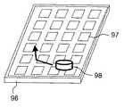
図12は、本発明の第9実施形態の電力供給システムの外観を示す外観図である。図12に示す電力供給システムは、図1〜図3に示す送電装置1が床に組み込まれていることを特徴としており、その一例を示している。図12において、96は床を示し、97は床96の送電装置1(不図示)が組み込まれている箇所を示しており、図5(b)に示す形態と同様の形態で送電装置1が複数組み込まれている。尚、組み込まれた送電装置1への商用電源(AC100V)供給のためのACプラグやコードは図示されていないが、床96の内部に設置された電源コード等を介して各送電装置1に商用電源が供給されるようになっている。 FIG. 12 is an external view showing the external appearance of the power supply system according to the ninth embodiment of the present invention. The power supply system shown in FIG. 12 is characterized in that the
また、98は床96を掃除する掃除ロボットを示している。掃除ロボット98は、図3に示す携帯電話機2と同様に送電装置1に対応した電力調整手段を有する受電機器であり、送電装置1は、送電装置1が組み込まれている箇所97の上に掃除ロボット98が位置したときに、上述のようにして、掃除ロボット98の必要な電力を検知し、送電する電力を調整して送電する。このようにして、掃除ロボット98は走行しながら充電を行なうことができるため、長時間動きつづけることが可能である。また、送電装置1は床96の中に組み込まれているため、床96に凹凸部が発生することがなく、掃除ロボット98はスムーズに動くことが出来る。また、掃除ロボット98の機種やメーカーを問わず充電が可能であり、携帯電話機、ノートパソコン、デジタルカメラ、携帯ゲーム機等の他の機器の充電も行なうことが可能である。また、本実施形態では、送電装置1は床96に組み込まれているが、床の上に敷くじゅうたん、カーペット、畳等の敷物に送電装置1を組み込むことも可能であり、その場合にも同様の効果が得られる。 Reference numeral 98 denotes a cleaning robot for cleaning the
以上、説明したように、本発明に係る電力供給システムを搭載した送電装置1は、受電機器の電力に応じて必要な送電電力を大電力、中電力、小電力の3段階に切り替えて送電することができるので、1つの送電装置で異なる種類の電子機器に電力を供給することができる。また、送電装置1は、机の天板、棚板、鍵のかかるロッカーの底板、受電機器のホルダ、車のダッシュボード及び/またはコンソールボックス、表面シート、壁または器具の側面、床または床に敷く敷物に組み込まれているので、省スペースを図ることができる。 As described above, the
尚、以上の説明は、本発明の実施形態の電力供給システムを搭載した装置として送電装置と携帯電話機を例に説明したが、本発明に係る電力供給システムは、送電装置と携帯電話機に限らず、他の電子機器にも適用できる。また、送電装置1が、机の天板、棚板、鍵のかかるロッカーの底板、受電機器のホルダ、車のダッシュボード及び/またはコンソールボックス、表面シート、床、床に敷く敷物、壁に組み込まれている例を示したが、他の器具や部材等に組み込まれていても構わない。また、本発明は上述の実施形態に限定されるものではなく、本発明の趣旨を逸脱しない範囲において各部の構成等を適宜に変更して実施することも可能である。 In the above description, a power transmission device and a mobile phone are described as examples of devices on which the power supply system of the embodiment of the present invention is mounted. However, the power supply system according to the present invention is not limited to a power transmission device and a mobile phone. It can also be applied to other electronic devices. In addition, the
本発明によれば、1次側コイルと、商用電源を整流平滑して得た直流電圧をスイッチングしたパルス電圧を前記1次側コイルに与える1次側回路とを有する送電装置と、前記1次側コイルと磁気結合される2次側コイルと、該2次側コイルに誘起される誘起電圧を整流平滑する2次側回路とを有する受電機器とから成り、前記受電機器の電力に応じて送電電力を調整する電力調整手段を備えた電力供給システムにおいて、前記送電装置が器具に組み込まれているので、1つの送電装置で異なる種類の電子機器に電力を供給することができるとともに省スペースを可能にした電力供給システムが実現できる。 According to the present invention, a power transmission device including a primary side coil and a primary side circuit that supplies a pulse voltage obtained by switching a DC voltage obtained by rectifying and smoothing a commercial power source to the primary side coil, and the primary A power receiving device having a secondary side coil magnetically coupled to the side coil and a secondary side circuit that rectifies and smoothes an induced voltage induced in the secondary side coil, and transmits power according to the power of the power receiving device. In the power supply system provided with the power adjusting means for adjusting the power, since the power transmission device is incorporated in the appliance, it is possible to supply power to different types of electronic devices with one power transmission device and to save space An electric power supply system can be realized.
1 送電装置
1a ACプラグ
1b コード
2 携帯電話機(受電機器)
3 ノートパソコン(受電機器)
10 1次側回路
11 1次側コイル
12 2次側コイル
13 2次側回路
14 充電制御回路
15 1次側コア(フェライト)
16 2次側コア(フェライト)
21、25、41 整流回路
22 スイッチング回路
23 トランス
24 送電制御IC(電力調整手段)
31 LED表示回路
32 電力切替回路
33 送電可否判定回路
34 電力量判定回路
35 満充電判定回路
36 復調回路
37 搬送波発振回路
42 受電制御IC(電力調整手段)
43 クロック抽出回路
44 パワーオンリセット回路
45 変調回路
46 電圧クランプ回路
47 レギュレータ
51、94 書斎机
51a、52a、53a、54a 天板(器具)
52 会議机
53 飲食店の机
54 電車の机
61 棚
61a 棚板(器具)
71 ロッカー
72 収納スペース
72a 底板(器具)
73 扉
74 鍵
81a 壁
91 ホルダ(器具)
92a ダッシュボード(器具)
93 コンソールボックス(器具)
95a 表面シート(器具)
96 床
98 掃除ロボット
C1、C2、C3、C4 コンデンサ
L1、L2、L3 コイル
R1、R2 抵抗
LED1、LED2 発光ダイオード
TR1、TR2、TR11、TR12、TR13 トランジスタDESCRIPTION OF
3. Notebook PC (power receiving device)
DESCRIPTION OF
16 Secondary core (ferrite)
21, 25, 41
DESCRIPTION OF SYMBOLS 31 LED display circuit 32
43
52
71
73
92a Dashboard
93 Console box (equipment)
95a Surface sheet (equipment)
96 Floor 98 Cleaning robot C1, C2, C3, C4 Capacitor L1, L2, L3 Coil R1, R2 Resistance LED1, LED2 Light emitting diode TR1, TR2, TR11, TR12, TR13 Transistor
Claims (13)
Translated fromJapanese前記送電装置が器具に組み込まれていることを特徴とする電力供給システム。In a power supply system that supplies power in an electrically non-contact manner from a power transmission device to which commercial power is supplied to a power receiving device,
The power supply system, wherein the power transmission device is incorporated in an appliance.
前記送電装置が器具に組み込まれていることを特徴とする電力供給システム。In a power supply system for supplying power in an electrically non-contact manner by adjusting transmission power according to the power of the power receiving device from the power transmission device to which commercial power is supplied,
The power supply system, wherein the power transmission device is incorporated in an appliance.
前記1次側コイルと磁気結合される2次側コイルと、該2次側コイルに誘起される誘起電圧を整流平滑する2次側回路とを有する受電機器と、
から成り、前記受電機器の電力に応じて送電電力を調整する電力調整手段を備えた電力供給システムにおいて、
前記送電装置が器具に組み込まれていることを特徴とする電力供給システム。A power transmission device having a primary side coil, and a primary side circuit that applies a pulse voltage obtained by switching a DC voltage obtained by rectifying and smoothing a commercial power source to the primary side coil;
A power receiving device having a secondary coil magnetically coupled to the primary coil, and a secondary circuit for rectifying and smoothing an induced voltage induced in the secondary coil;
In a power supply system comprising a power adjustment means for adjusting transmission power according to the power of the power receiving device,
The power supply system, wherein the power transmission device is incorporated in an appliance.
前記送電装置が床または床に敷く敷物または壁に組み込まれていることを特徴とする電力供給システム。In a power supply system that supplies power in an electrically non-contact manner from a power transmission device to which commercial power is supplied to a power receiving device,
The power supply system, wherein the power transmission device is incorporated in a floor or a rug or wall laid on the floor.
前記送電装置が床または床に敷く敷物または壁に組み込まれていることを特徴とする電力供給システム。In a power supply system for supplying power in an electrically non-contact manner by adjusting transmission power according to the power of the power receiving device from the power transmission device to which commercial power is supplied,
The power supply system, wherein the power transmission device is incorporated in a floor or a rug or wall laid on the floor.
前記1次側コイルと磁気結合される2次側コイルと、該2次側コイルに誘起される誘起電圧を整流平滑する2次側回路とを有する受電機器と、
から成り、前記受電機器の電力に応じて送電電力を調整する電力調整手段を備えた電力供給システムにおいて、
前記送電装置が床または床に敷く敷物または壁に組み込まれていることを特徴とする電力供給システム。A power transmission device having a primary side coil, and a primary side circuit that applies a pulse voltage obtained by switching a DC voltage obtained by rectifying and smoothing a commercial power source to the primary side coil;
A power receiving device having a secondary coil magnetically coupled to the primary coil, and a secondary circuit for rectifying and smoothing an induced voltage induced in the secondary coil;
In a power supply system comprising a power adjustment means for adjusting transmission power according to the power of the power receiving device,
The power supply system, wherein the power transmission device is incorporated in a floor or a rug or wall laid on the floor.
Priority Applications (3)
| Application Number | Priority Date | Filing Date | Title |
|---|---|---|---|
| JP2003340772AJP2005110412A (en) | 2003-09-30 | 2003-09-30 | Power supply system |
| US10/947,425US7233137B2 (en) | 2003-09-30 | 2004-09-23 | Power supply system |
| CNA200410085133XACN1604426A (en) | 2003-09-30 | 2004-09-30 | Power Systems |
Applications Claiming Priority (1)
| Application Number | Priority Date | Filing Date | Title |
|---|---|---|---|
| JP2003340772AJP2005110412A (en) | 2003-09-30 | 2003-09-30 | Power supply system |
Publications (1)
| Publication Number | Publication Date |
|---|---|
| JP2005110412Atrue JP2005110412A (en) | 2005-04-21 |
Family
ID=34535570
Family Applications (1)
| Application Number | Title | Priority Date | Filing Date |
|---|---|---|---|
| JP2003340772APendingJP2005110412A (en) | 2003-09-30 | 2003-09-30 | Power supply system |
Country Status (1)
| Country | Link |
|---|---|
| JP (1) | JP2005110412A (en) |
Cited By (69)
| Publication number | Priority date | Publication date | Assignee | Title |
|---|---|---|---|---|
| JP2006336969A (en)* | 2005-06-03 | 2006-12-14 | Matsushita Electric Ind Co Ltd | Goods storage device |
| JP2006353042A (en)* | 2005-06-17 | 2006-12-28 | Ntt Docomo Inc | Power transmission device, power reception device, authentication / billing proxy device, charging system, power transmission method, power reception method, charging method |
| JP2007104868A (en)* | 2005-10-07 | 2007-04-19 | Toyota Motor Corp | VEHICLE CHARGING DEVICE, ELECTRIC DEVICE AND VEHICLE NON-CONTACT CHARGE SYSTEM |
| WO2008032746A1 (en)* | 2006-09-12 | 2008-03-20 | The University Of Tokyo | Power supply sheet and electrically connecting circuit |
| JP2008148242A (en)* | 2006-12-13 | 2008-06-26 | Sharp Corp | Mobile information terminal charging system |
| JP2008237612A (en)* | 2007-03-27 | 2008-10-09 | Matsushita Electric Works Ltd | cabinet |
| WO2009054221A1 (en)* | 2007-10-25 | 2009-04-30 | Toyota Jidosha Kabushiki Kaisha | Electric vehicle and power feeding apparatus for the vehicle |
| JP2009525715A (en)* | 2006-01-31 | 2009-07-09 | エルエス ケーブル リミテッド | Non-contact charging device provided with coil array, non-contact charging system and charging method |
| JP2009159683A (en)* | 2007-12-25 | 2009-07-16 | Panasonic Electric Works Co Ltd | Building with contactless power supply function and contactless power supply outlet |
| JP2009159685A (en)* | 2007-12-25 | 2009-07-16 | Panasonic Electric Works Co Ltd | Contactless power supply system |
| JP2010011584A (en)* | 2008-06-25 | 2010-01-14 | Seiko Epson Corp | Power transmission controller, power transmission device, power reception controller, power receiver, and electronic equipment |
| JP2010035408A (en)* | 2008-06-25 | 2010-02-12 | Seiko Epson Corp | Power transmission control device, power transmission device, power receiving control device, power receiving apparatus, electronic apparatus, method for controlling power transmission, and method for controlling power receiving |
| JP2010508008A (en)* | 2006-10-26 | 2010-03-11 | コーニンクレッカ フィリップス エレクトロニクス エヌ ヴィ | Floor covering and inductive power system |
| JP2010517502A (en)* | 2007-01-29 | 2010-05-20 | パワーマット リミテッド | Pinless power coupling |
| JP2010520741A (en)* | 2007-03-05 | 2010-06-10 | ランダル ミッチ | ELECTRIC DEVICE FOR ELECTRONIC DEVICE AND METHOD FOR SUPPLYING ELECTRIC DEVICE |
| JP2010283913A (en)* | 2009-06-02 | 2010-12-16 | Panasonic Electric Works Co Ltd | Power supply device |
| JP2011501633A (en)* | 2007-10-09 | 2011-01-06 | パワーマット リミテッド | Inductive power supply system in the interface |
| EP2317624A1 (en)* | 2009-10-30 | 2011-05-04 | TDK Corporation | Wireless power feeder, wireless power transmission system, and table and table lamp using the same |
| JP2011517925A (en)* | 2009-01-05 | 2011-06-16 | エル アンド ピー プロパティ マネジメント カンパニー | Inductive coupling work surface |
| JP2011518316A (en)* | 2008-02-28 | 2011-06-23 | イーエルエスアイ テクノロジース オーワイ | Method and system for communicating information |
| US8061864B2 (en) | 2009-05-12 | 2011-11-22 | Kimball International, Inc. | Furniture with wireless power |
| JP2012517794A (en)* | 2009-02-10 | 2012-08-02 | クアルコム,インコーポレイテッド | Wireless power transmission for furniture and building elements |
| JP2012517795A (en)* | 2009-02-10 | 2012-08-02 | クアルコム,インコーポレイテッド | Wireless power transfer for vehicles |
| JP2012517793A (en)* | 2009-02-10 | 2012-08-02 | クアルコム,インコーポレイテッド | Power transmission system, apparatus and method in public facilities |
| JP2012518380A (en)* | 2009-02-13 | 2012-08-09 | クアルコム,インコーポレイテッド | Wireless power from renewable energy |
| JP2012518975A (en)* | 2009-02-24 | 2012-08-16 | エル アンド ピー プロパティ マネジメント カンパニー | Inductively coupled shelves and storage containers |
| JP2012178964A (en)* | 2011-02-01 | 2012-09-13 | Honda Motor Co Ltd | Contactless electric power transmission device |
| WO2012164742A1 (en) | 2011-06-03 | 2012-12-06 | トヨタ自動車株式会社 | Vehicle and power transmission/reception system |
| WO2012164743A1 (en) | 2011-06-03 | 2012-12-06 | トヨタ自動車株式会社 | Vehicle, electric device, and power transmission/reception system |
| JP2013016497A (en)* | 2006-03-23 | 2013-01-24 | Access Business Group Internatl Llc | System and method for food preparation |
| JPWO2011042974A1 (en)* | 2009-10-08 | 2013-02-28 | 株式会社日立製作所 | Wireless power transmission system and wireless power transmission device |
| JP2013121281A (en)* | 2011-12-08 | 2013-06-17 | Honda Access Corp | On-vehicle charging device |
| JP2013128400A (en)* | 2011-12-16 | 2013-06-27 | Tdk Corp | Wireless power supply device, and wireless power transmission system |
| JP2013172628A (en)* | 2012-02-23 | 2013-09-02 | Panasonic Corp | On-vehicle charger and automobile mounting the same thereon |
| US8618695B2 (en) | 2008-06-02 | 2013-12-31 | Powermat Technologies, Ltd | Appliance mounted power outlets |
| US8624750B2 (en) | 2007-10-09 | 2014-01-07 | Powermat Technologies, Ltd. | System and method for inductive power provision over an extended surface |
| US8626461B2 (en) | 2007-03-22 | 2014-01-07 | Powermat Technologies, Ltd | Efficiency monitor for inductive power transmission |
| JP2014030342A (en)* | 2008-05-13 | 2014-02-13 | Qualcomm Incorporated | Transmit power control for wireless charging system |
| US8754548B2 (en) | 2010-04-08 | 2014-06-17 | Samsung Electronics Co., Ltd. | Resonance power receiving apparatus and method with wireless power transform function, and resonance device |
| JP2014113058A (en)* | 2006-11-08 | 2014-06-19 | Panasonic Corp | Noncontact charger, electronic equipment and noncontact charging system |
| US8766488B2 (en) | 2007-09-25 | 2014-07-01 | Powermat Technologies, Ltd. | Adjustable inductive power transmission platform |
| US8829727B2 (en) | 2009-10-30 | 2014-09-09 | Tdk Corporation | Wireless power feeder, wireless power transmission system, and table and table lamp using the same |
| US8854224B2 (en) | 2009-02-10 | 2014-10-07 | Qualcomm Incorporated | Conveying device information relating to wireless charging |
| JP2015029415A (en)* | 2008-03-13 | 2015-02-12 | アクセス ビジネス グループ インターナショナル リミテッド ライアビリティ カンパニー | Inductive charging system having a plurality of primary coils |
| US8981598B2 (en) | 2008-07-02 | 2015-03-17 | Powermat Technologies Ltd. | Energy efficient inductive power transmission system and method |
| JP2015083148A (en)* | 2010-01-19 | 2015-04-30 | パナソニックIpマネジメント株式会社 | Furniture with noncontact power feed function |
| US9035501B2 (en) | 2008-03-17 | 2015-05-19 | Powermat Technologies, Ltd. | System and method for providing simple feedback signals indicating if more or less power is required during inductive power transmission |
| JP2015104252A (en)* | 2013-11-26 | 2015-06-04 | 矢崎総業株式会社 | Wireless power supply system |
| JP2015122894A (en)* | 2013-12-24 | 2015-07-02 | 株式会社ヘッズ | Waterproof non-contact feeding device |
| US9124308B2 (en) | 2009-05-12 | 2015-09-01 | Kimball International, Inc. | Furniture with wireless power |
| US9124121B2 (en) | 2008-09-23 | 2015-09-01 | Powermat Technologies, Ltd. | Combined antenna and inductive power receiver |
| JP2015526054A (en)* | 2012-07-10 | 2015-09-07 | サムスン エレクトロニクス カンパニー リミテッド | Method and power transmitter for controlling power transmission |
| US9197093B2 (en) | 2010-12-24 | 2015-11-24 | Toyota Jidosha Kabushiki Kaisha | Non-contact charging system, non-contact charging method, non-contact charging type vehicle, and non-contact charging management apparatus |
| US9312924B2 (en) | 2009-02-10 | 2016-04-12 | Qualcomm Incorporated | Systems and methods relating to multi-dimensional wireless charging |
| US9325195B2 (en) | 2009-08-19 | 2016-04-26 | Powermat Technologies Ltd. | Inductively chargeable power pack |
| US9331750B2 (en) | 2008-03-17 | 2016-05-03 | Powermat Technologies Ltd. | Wireless power receiver and host control interface thereof |
| US9337902B2 (en) | 2008-03-17 | 2016-05-10 | Powermat Technologies Ltd. | System and method for providing wireless power transfer functionality to an electrical device |
| US9478991B2 (en) | 2010-04-30 | 2016-10-25 | Powermat Technologies Ltd. | System and method for transferring power inductively over an extended region |
| US9583953B2 (en) | 2009-02-10 | 2017-02-28 | Qualcomm Incorporated | Wireless power transfer for portable enclosures |
| JP2018033312A (en)* | 2017-10-31 | 2018-03-01 | 株式会社ヘッズ | Water-resistant non-contact feeder |
| JP2018038819A (en)* | 2016-09-02 | 2018-03-15 | グローエ アクチエンゲゼルシャフトGrohe AG | Installation unit used in sanitary space |
| US9960642B2 (en) | 2008-03-17 | 2018-05-01 | Powermat Technologies Ltd. | Embedded interface for wireless power transfer to electrical devices |
| US9960640B2 (en) | 2008-03-17 | 2018-05-01 | Powermat Technologies Ltd. | System and method for regulating inductive power transmission |
| US10068701B2 (en) | 2007-09-25 | 2018-09-04 | Powermat Technologies Ltd. | Adjustable inductive power transmission platform |
| CN108964224A (en)* | 2013-03-22 | 2018-12-07 | 松下知识产权经营株式会社 | The control method of power supply unit, power supply system and power supply unit |
| JP2019503068A (en)* | 2015-11-16 | 2019-01-31 | アモテック・カンパニー・リミテッド | Magnetic shielding unit for wireless power transmission and wireless power transmission module including the same |
| KR102093469B1 (en)* | 2018-11-16 | 2020-03-25 | 코마테크 주식회사 | Wireless power transfer device |
| JP2021023034A (en)* | 2019-07-29 | 2021-02-18 | 株式会社Subaru | On-vehicle non-contact charger and vehicle |
| US11979201B2 (en) | 2008-07-02 | 2024-05-07 | Powermat Technologies Ltd. | System and method for coded communication signals regulating inductive power transmissions |
- 2003
- 2003-09-30JPJP2003340772Apatent/JP2005110412A/enactivePending
Cited By (129)
| Publication number | Priority date | Publication date | Assignee | Title |
|---|---|---|---|---|
| JP2006336969A (en)* | 2005-06-03 | 2006-12-14 | Matsushita Electric Ind Co Ltd | Goods storage device |
| JP2006353042A (en)* | 2005-06-17 | 2006-12-28 | Ntt Docomo Inc | Power transmission device, power reception device, authentication / billing proxy device, charging system, power transmission method, power reception method, charging method |
| JP2007104868A (en)* | 2005-10-07 | 2007-04-19 | Toyota Motor Corp | VEHICLE CHARGING DEVICE, ELECTRIC DEVICE AND VEHICLE NON-CONTACT CHARGE SYSTEM |
| JP2009525715A (en)* | 2006-01-31 | 2009-07-09 | エルエス ケーブル リミテッド | Non-contact charging device provided with coil array, non-contact charging system and charging method |
| US8159183B2 (en) | 2006-01-31 | 2012-04-17 | Ls Cable & System Ltd. | Contact-less power supply, contact-less charger systems and method for charging rechargeable battery cell |
| JP2013016497A (en)* | 2006-03-23 | 2013-01-24 | Access Business Group Internatl Llc | System and method for food preparation |
| WO2008032746A1 (en)* | 2006-09-12 | 2008-03-20 | The University Of Tokyo | Power supply sheet and electrically connecting circuit |
| JP2010508008A (en)* | 2006-10-26 | 2010-03-11 | コーニンクレッカ フィリップス エレクトロニクス エヌ ヴィ | Floor covering and inductive power system |
| JP2014113058A (en)* | 2006-11-08 | 2014-06-19 | Panasonic Corp | Noncontact charger, electronic equipment and noncontact charging system |
| US9407109B2 (en) | 2006-11-08 | 2016-08-02 | Panasonic Intellectual Property Management Co., Ltd. | Contactless battery charger, electronic device, battery pack, and contactless charging system |
| US9362779B2 (en) | 2006-11-08 | 2016-06-07 | Panasonic Intellectual Property Management Co., Ltd. | Contactless battery charger, electronic device, battery pack, and contactless charging system |
| JP2008148242A (en)* | 2006-12-13 | 2008-06-26 | Sharp Corp | Mobile information terminal charging system |
| US11611240B2 (en) | 2007-01-29 | 2023-03-21 | Powermat Technologies Ltd. | Pinless power coupling |
| US11437852B2 (en) | 2007-01-29 | 2022-09-06 | Powermat Technologies Ltd. | Pinless power coupling |
| US12308656B2 (en) | 2007-01-29 | 2025-05-20 | Powermat Technologies Ltd. | Pinless power coupling |
| JP2010517502A (en)* | 2007-01-29 | 2010-05-20 | パワーマット リミテッド | Pinless power coupling |
| US11881717B2 (en) | 2007-01-29 | 2024-01-23 | Powermat Technologies Ltd. | Pinless power coupling |
| US11114895B2 (en) | 2007-01-29 | 2021-09-07 | Powermat Technologies, Ltd. | Pinless power coupling |
| JP2010520741A (en)* | 2007-03-05 | 2010-06-10 | ランダル ミッチ | ELECTRIC DEVICE FOR ELECTRONIC DEVICE AND METHOD FOR SUPPLYING ELECTRIC DEVICE |
| US8965720B2 (en) | 2007-03-22 | 2015-02-24 | Powermat Technologies, Ltd. | Efficiency monitor for inductive power transmission |
| US8626461B2 (en) | 2007-03-22 | 2014-01-07 | Powermat Technologies, Ltd | Efficiency monitor for inductive power transmission |
| US10742076B2 (en) | 2007-03-22 | 2020-08-11 | Samsung Electronics Co., Ltd. | Inductive power outlet locator |
| US9362049B2 (en) | 2007-03-22 | 2016-06-07 | Powermat Technologies Ltd. | Efficiency monitor for inductive power transmission |
| US8749097B2 (en) | 2007-03-22 | 2014-06-10 | Powermat Technologies, Ltd | System and method for controlling power transfer across an inductive power coupling |
| JP2008237612A (en)* | 2007-03-27 | 2008-10-09 | Matsushita Electric Works Ltd | cabinet |
| US8766488B2 (en) | 2007-09-25 | 2014-07-01 | Powermat Technologies, Ltd. | Adjustable inductive power transmission platform |
| US10068701B2 (en) | 2007-09-25 | 2018-09-04 | Powermat Technologies Ltd. | Adjustable inductive power transmission platform |
| US8624750B2 (en) | 2007-10-09 | 2014-01-07 | Powermat Technologies, Ltd. | System and method for inductive power provision over an extended surface |
| JP2011501633A (en)* | 2007-10-09 | 2011-01-06 | パワーマット リミテッド | Inductive power supply system in the interface |
| WO2009054221A1 (en)* | 2007-10-25 | 2009-04-30 | Toyota Jidosha Kabushiki Kaisha | Electric vehicle and power feeding apparatus for the vehicle |
| US8008888B2 (en) | 2007-10-25 | 2011-08-30 | Toyota Jidosha Kabushiki Kaisha | Electrical powered vehicle and power feeding device for vehicle |
| US9421868B2 (en) | 2007-10-25 | 2016-08-23 | Toyota Jidosha Kabushiki Kaisha | Electrical powered vehicle and power feeding device for vehicle |
| US9024575B2 (en) | 2007-10-25 | 2015-05-05 | Toyota Jidosha Kabushiki Kaisha | Electrical powered vehicle and power feeding device for vehicle |
| US9180779B2 (en) | 2007-10-25 | 2015-11-10 | Toyota Jidosha Kabushiki Kaisha | Electrical powered vehicle and power feeding device for vehicle |
| JP2009159683A (en)* | 2007-12-25 | 2009-07-16 | Panasonic Electric Works Co Ltd | Building with contactless power supply function and contactless power supply outlet |
| JP2009159685A (en)* | 2007-12-25 | 2009-07-16 | Panasonic Electric Works Co Ltd | Contactless power supply system |
| JP2011518316A (en)* | 2008-02-28 | 2011-06-23 | イーエルエスアイ テクノロジース オーワイ | Method and system for communicating information |
| JP2015029415A (en)* | 2008-03-13 | 2015-02-12 | アクセス ビジネス グループ インターナショナル リミテッド ライアビリティ カンパニー | Inductive charging system having a plurality of primary coils |
| US9685795B2 (en) | 2008-03-17 | 2017-06-20 | Powermat Technologies Ltd. | Transmission-guard system and method for an inductive power supply |
| US9331750B2 (en) | 2008-03-17 | 2016-05-03 | Powermat Technologies Ltd. | Wireless power receiver and host control interface thereof |
| US9960642B2 (en) | 2008-03-17 | 2018-05-01 | Powermat Technologies Ltd. | Embedded interface for wireless power transfer to electrical devices |
| US9960640B2 (en) | 2008-03-17 | 2018-05-01 | Powermat Technologies Ltd. | System and method for regulating inductive power transmission |
| US10033231B2 (en) | 2008-03-17 | 2018-07-24 | Powermat Technologies Ltd. | System and method for providing wireless power transfer functionality to an electrical device |
| US9337902B2 (en) | 2008-03-17 | 2016-05-10 | Powermat Technologies Ltd. | System and method for providing wireless power transfer functionality to an electrical device |
| US10205346B2 (en) | 2008-03-17 | 2019-02-12 | Powermat Technologies Ltd. | Wireless power receiver and host control interface thereof |
| US9035501B2 (en) | 2008-03-17 | 2015-05-19 | Powermat Technologies, Ltd. | System and method for providing simple feedback signals indicating if more or less power is required during inductive power transmission |
| US9136734B2 (en) | 2008-03-17 | 2015-09-15 | Powermat Technologies, Ltd. | Transmission-guard system and method for an inductive power supply |
| US9083204B2 (en) | 2008-03-17 | 2015-07-14 | Powermat Technologies, Ltd. | Transmission-guard system and method for an inductive power supply |
| US11837399B2 (en) | 2008-03-17 | 2023-12-05 | Powermat Technologies, Ltd. | Transmission-guard system and method for an inductive power supply |
| US9048696B2 (en) | 2008-03-17 | 2015-06-02 | Powermat Technologies, Ltd. | Transmission-guard system and method for an inductive power supply |
| US8878393B2 (en) | 2008-05-13 | 2014-11-04 | Qualcomm Incorporated | Wireless power transfer for vehicles |
| US9236771B2 (en) | 2008-05-13 | 2016-01-12 | Qualcomm Incorporated | Method and apparatus for adaptive tuning of wireless power transfer |
| JP2014030342A (en)* | 2008-05-13 | 2014-02-13 | Qualcomm Incorporated | Transmit power control for wireless charging system |
| US9130407B2 (en) | 2008-05-13 | 2015-09-08 | Qualcomm Incorporated | Signaling charging in wireless power environment |
| US8892035B2 (en) | 2008-05-13 | 2014-11-18 | Qualcomm Incorporated | Repeaters for enhancement of wireless power transfer |
| US9178387B2 (en) | 2008-05-13 | 2015-11-03 | Qualcomm Incorporated | Receive antenna for wireless power transfer |
| US8965461B2 (en) | 2008-05-13 | 2015-02-24 | Qualcomm Incorporated | Reverse link signaling via receive antenna impedance modulation |
| US9954399B2 (en) | 2008-05-13 | 2018-04-24 | Qualcomm Incorporated | Reverse link signaling via receive antenna impedance modulation |
| US9991747B2 (en) | 2008-05-13 | 2018-06-05 | Qualcomm Incorporated | Signaling charging in wireless power environment |
| US9184632B2 (en) | 2008-05-13 | 2015-11-10 | Qualcomm Incorporated | Wireless power transfer for furnishings and building elements |
| US9190875B2 (en) | 2008-05-13 | 2015-11-17 | Qualcomm Incorporated | Method and apparatus with negative resistance in wireless power transfers |
| US8618695B2 (en) | 2008-06-02 | 2013-12-31 | Powermat Technologies, Ltd | Appliance mounted power outlets |
| US8274254B2 (en) | 2008-06-25 | 2012-09-25 | Seiko Epson Corporation | Power transmission control device, power transmission device, power receiving control device, power receiving device, electronic apparatus, method for controlling power transmission, and method for controlling power receiving |
| JP2010035408A (en)* | 2008-06-25 | 2010-02-12 | Seiko Epson Corp | Power transmission control device, power transmission device, power receiving control device, power receiving apparatus, electronic apparatus, method for controlling power transmission, and method for controlling power receiving |
| JP2010011584A (en)* | 2008-06-25 | 2010-01-14 | Seiko Epson Corp | Power transmission controller, power transmission device, power reception controller, power receiver, and electronic equipment |
| US11387688B2 (en) | 2008-07-02 | 2022-07-12 | Powermat Technologies, Ltd. | System and method for coded communication signals regulating inductive power transmissions |
| US9006937B2 (en) | 2008-07-02 | 2015-04-14 | Powermat Technologies Ltd. | System and method for enabling ongoing inductive power transmission |
| US11979201B2 (en) | 2008-07-02 | 2024-05-07 | Powermat Technologies Ltd. | System and method for coded communication signals regulating inductive power transmissions |
| US9099894B2 (en) | 2008-07-02 | 2015-08-04 | Powermat Technologies, Ltd. | System and method for coded communication signals regulating inductive power transmission |
| US8981598B2 (en) | 2008-07-02 | 2015-03-17 | Powermat Technologies Ltd. | Energy efficient inductive power transmission system and method |
| US9124121B2 (en) | 2008-09-23 | 2015-09-01 | Powermat Technologies, Ltd. | Combined antenna and inductive power receiver |
| JP2014131472A (en)* | 2009-01-05 | 2014-07-10 | L & P Property Management Co | Inductive coupling console |
| JP2011517925A (en)* | 2009-01-05 | 2011-06-16 | エル アンド ピー プロパティ マネジメント カンパニー | Inductive coupling work surface |
| US9583953B2 (en) | 2009-02-10 | 2017-02-28 | Qualcomm Incorporated | Wireless power transfer for portable enclosures |
| US9312924B2 (en) | 2009-02-10 | 2016-04-12 | Qualcomm Incorporated | Systems and methods relating to multi-dimensional wireless charging |
| JP2015165766A (en)* | 2009-02-10 | 2015-09-17 | クアルコム,インコーポレイテッド | Apparatus and method of wireless power transfer for furniture and building elements |
| JP2012517794A (en)* | 2009-02-10 | 2012-08-02 | クアルコム,インコーポレイテッド | Wireless power transmission for furniture and building elements |
| JP2012517793A (en)* | 2009-02-10 | 2012-08-02 | クアルコム,インコーポレイテッド | Power transmission system, apparatus and method in public facilities |
| US8854224B2 (en) | 2009-02-10 | 2014-10-07 | Qualcomm Incorporated | Conveying device information relating to wireless charging |
| JP2012517795A (en)* | 2009-02-10 | 2012-08-02 | クアルコム,インコーポレイテッド | Wireless power transfer for vehicles |
| US8963486B2 (en) | 2009-02-13 | 2015-02-24 | Qualcomm Incorporated | Wireless power from renewable energy |
| JP2012518380A (en)* | 2009-02-13 | 2012-08-09 | クアルコム,インコーポレイテッド | Wireless power from renewable energy |
| JP2012518975A (en)* | 2009-02-24 | 2012-08-16 | エル アンド ピー プロパティ マネジメント カンパニー | Inductively coupled shelves and storage containers |
| KR101556027B1 (en) | 2009-02-24 | 2015-09-25 | 엘앤드피 프라퍼티 매니지먼트 캄파니 | Inductively coupled shelving and storage containers |
| US8262244B2 (en) | 2009-05-12 | 2012-09-11 | Kimball International, Inc. | Furniture with wireless power |
| US9124308B2 (en) | 2009-05-12 | 2015-09-01 | Kimball International, Inc. | Furniture with wireless power |
| US8061864B2 (en) | 2009-05-12 | 2011-11-22 | Kimball International, Inc. | Furniture with wireless power |
| US9572424B2 (en) | 2009-05-12 | 2017-02-21 | Kimball International, Inc. | Furniture with wireless power |
| JP2010283913A (en)* | 2009-06-02 | 2010-12-16 | Panasonic Electric Works Co Ltd | Power supply device |
| US9325195B2 (en) | 2009-08-19 | 2016-04-26 | Powermat Technologies Ltd. | Inductively chargeable power pack |
| JPWO2011042974A1 (en)* | 2009-10-08 | 2013-02-28 | 株式会社日立製作所 | Wireless power transmission system and wireless power transmission device |
| CN102055249B (en)* | 2009-10-30 | 2014-06-18 | Tdk株式会社 | Wireless power feeder, wireless power transmission system, and table and table lamp using the same |
| EP2317624A1 (en)* | 2009-10-30 | 2011-05-04 | TDK Corporation | Wireless power feeder, wireless power transmission system, and table and table lamp using the same |
| US8581444B2 (en) | 2009-10-30 | 2013-11-12 | Tdk Corporation | Wireless power feeder, wireless power transmission system, and table and table lamp using the same |
| CN102055249A (en)* | 2009-10-30 | 2011-05-11 | Tdk株式会社 | Wireless power feeder, wireless power transmission system, and table and table lamp using the same |
| US8829727B2 (en) | 2009-10-30 | 2014-09-09 | Tdk Corporation | Wireless power feeder, wireless power transmission system, and table and table lamp using the same |
| JP2015083148A (en)* | 2010-01-19 | 2015-04-30 | パナソニックIpマネジメント株式会社 | Furniture with noncontact power feed function |
| US8754548B2 (en) | 2010-04-08 | 2014-06-17 | Samsung Electronics Co., Ltd. | Resonance power receiving apparatus and method with wireless power transform function, and resonance device |
| US9478991B2 (en) | 2010-04-30 | 2016-10-25 | Powermat Technologies Ltd. | System and method for transferring power inductively over an extended region |
| US9197093B2 (en) | 2010-12-24 | 2015-11-24 | Toyota Jidosha Kabushiki Kaisha | Non-contact charging system, non-contact charging method, non-contact charging type vehicle, and non-contact charging management apparatus |
| USRE48659E1 (en) | 2010-12-24 | 2021-07-27 | Toyota Jidosha Kabushiki Kaisha | Non-contact charging system, non-contact charging method, non-contact charging type vehicle, and non-contact charging management apparatus |
| JP2012178964A (en)* | 2011-02-01 | 2012-09-13 | Honda Motor Co Ltd | Contactless electric power transmission device |
| US9106107B2 (en) | 2011-02-01 | 2015-08-11 | Honda Motor Co., Ltd. | Contactless power transmission device provided in a vehicle for charging an electronic device |
| KR20140022921A (en) | 2011-06-03 | 2014-02-25 | 도요타지도샤가부시키가이샤 | Vehicle and power transmission/reception system |
| US9381878B2 (en) | 2011-06-03 | 2016-07-05 | Toyota Jidosha Kabushiki Kaisha | Vehicle and power transmission/reception system |
| WO2012164743A1 (en) | 2011-06-03 | 2012-12-06 | トヨタ自動車株式会社 | Vehicle, electric device, and power transmission/reception system |
| WO2012164742A1 (en) | 2011-06-03 | 2012-12-06 | トヨタ自動車株式会社 | Vehicle and power transmission/reception system |
| US9162581B2 (en) | 2011-06-03 | 2015-10-20 | Toyota Jidosha Kabushiki Kaisha | Vehicle, electric device, and power transmission/reception system |
| JP2013121281A (en)* | 2011-12-08 | 2013-06-17 | Honda Access Corp | On-vehicle charging device |
| JP2013128400A (en)* | 2011-12-16 | 2013-06-27 | Tdk Corp | Wireless power supply device, and wireless power transmission system |
| JP2013172628A (en)* | 2012-02-23 | 2013-09-02 | Panasonic Corp | On-vehicle charger and automobile mounting the same thereon |
| US11552480B2 (en) | 2012-07-10 | 2023-01-10 | Samsung Electronics Co., Ltd. | Method and power transmitter for controlling power transmission |
| US9876378B2 (en) | 2012-07-10 | 2018-01-23 | Samsung Electronics Co., Ltd | Method and power transmitter for controlling power transmission |
| US10797531B1 (en) | 2012-07-10 | 2020-10-06 | Samsung Electronics Co., Ltd. | Method and power transmitter for controlling power transmission |
| US10141773B2 (en) | 2012-07-10 | 2018-11-27 | Samsung Electronics Co., Ltd | Method and power transmitter for controlling power transmission |
| US10637275B2 (en) | 2012-07-10 | 2020-04-28 | Samsung Electronics Co., Ltd | Method and power transmitter for controlling power transmission |
| JP2015526054A (en)* | 2012-07-10 | 2015-09-07 | サムスン エレクトロニクス カンパニー リミテッド | Method and power transmitter for controlling power transmission |
| US10340726B2 (en) | 2012-07-10 | 2019-07-02 | Samsung Electronics Co., Ltd | Method and power transmitter for controlling power transmission |
| CN108964224A (en)* | 2013-03-22 | 2018-12-07 | 松下知识产权经营株式会社 | The control method of power supply unit, power supply system and power supply unit |
| JP2015104252A (en)* | 2013-11-26 | 2015-06-04 | 矢崎総業株式会社 | Wireless power supply system |
| JP2015122894A (en)* | 2013-12-24 | 2015-07-02 | 株式会社ヘッズ | Waterproof non-contact feeding device |
| JP2019503068A (en)* | 2015-11-16 | 2019-01-31 | アモテック・カンパニー・リミテッド | Magnetic shielding unit for wireless power transmission and wireless power transmission module including the same |
| US11412644B2 (en) | 2015-11-16 | 2022-08-09 | Amotech Co., Ltd. | Magnetic shielding unit for wireless power transmission and wireless power transmission module including same |
| JP2018038819A (en)* | 2016-09-02 | 2018-03-15 | グローエ アクチエンゲゼルシャフトGrohe AG | Installation unit used in sanitary space |
| JP7078364B2 (en) | 2016-09-02 | 2022-05-31 | グローエ アクチエンゲゼルシャフト | Installation unit used for sanitary space |
| JP2018033312A (en)* | 2017-10-31 | 2018-03-01 | 株式会社ヘッズ | Water-resistant non-contact feeder |
| KR102093469B1 (en)* | 2018-11-16 | 2020-03-25 | 코마테크 주식회사 | Wireless power transfer device |
| JP7253996B2 (en) | 2019-07-29 | 2023-04-07 | 株式会社Subaru | In-vehicle non-contact charging device and vehicle |
| JP2021023034A (en)* | 2019-07-29 | 2021-02-18 | 株式会社Subaru | On-vehicle non-contact charger and vehicle |
Similar Documents
| Publication | Publication Date | Title |
|---|---|---|
| JP2005110412A (en) | Power supply system | |
| US12027873B2 (en) | System and method for inductive charging of portable devices | |
| US7233137B2 (en) | Power supply system | |
| US11292349B2 (en) | System and method for powering or charging receivers or devices having small surface areas or volumes | |
| US20250096607A1 (en) | System and method for infrastructure, vehicle and internet of things wireless chargers | |
| CN101971453B (en) | System and method for inductive charging of portable devices | |
| JP2006141170A (en) | Power supply system, power transmission device and power reception device used therefor | |
| JP2005110409A (en) | Power supply system | |
| FI120853B (en) | Energy transfer device and method | |
| CN102318213B (en) | Wireless power transfer for vehicles | |
| CN101425702B (en) | Structure having a non-contact power transmitting device | |
| US9793721B2 (en) | Distributed charging of mobile devices | |
| US7378817B2 (en) | Inductive power adapter | |
| CN102835003B (en) | Non-contact power supply system | |
| US10115520B2 (en) | Systems and method for wireless power transfer | |
| US7852619B2 (en) | Information center for an appliance | |
| CN112825432A (en) | A wireless charging system and wireless charging method | |
| US20230006475A1 (en) | Wireless power transmission apparatus and method for controlling same | |
| KR20210140883A (en) | Wireless charging system | |
| HK1208963B (en) | System and method for inductive charging of portable devices |
Legal Events
| Date | Code | Title | Description |
|---|---|---|---|
| A621 | Written request for application examination | Free format text:JAPANESE INTERMEDIATE CODE: A621 Effective date:20050810 | |
| A977 | Report on retrieval | Free format text:JAPANESE INTERMEDIATE CODE: A971007 Effective date:20061204 | |
| A131 | Notification of reasons for refusal | Free format text:JAPANESE INTERMEDIATE CODE: A131 Effective date:20061212 | |
| A521 | Written amendment | Free format text:JAPANESE INTERMEDIATE CODE: A523 Effective date:20070202 | |
| A131 | Notification of reasons for refusal | Free format text:JAPANESE INTERMEDIATE CODE: A131 Effective date:20070710 | |
| A521 | Written amendment | Free format text:JAPANESE INTERMEDIATE CODE: A523 Effective date:20070821 | |
| RD01 | Notification of change of attorney | Free format text:JAPANESE INTERMEDIATE CODE: A7421 Effective date:20070906 | |
| A131 | Notification of reasons for refusal | Free format text:JAPANESE INTERMEDIATE CODE: A131 Effective date:20080212 | |
| A02 | Decision of refusal | Free format text:JAPANESE INTERMEDIATE CODE: A02 Effective date:20080624 |