JP2005110357A - Noncontact charging electronic apparatus - Google Patents
Noncontact charging electronic apparatusDownload PDFInfo
- Publication number
- JP2005110357A JP2005110357AJP2003337390AJP2003337390AJP2005110357AJP 2005110357 AJP2005110357 AJP 2005110357AJP 2003337390 AJP2003337390 AJP 2003337390AJP 2003337390 AJP2003337390 AJP 2003337390AJP 2005110357 AJP2005110357 AJP 2005110357A
- Authority
- JP
- Japan
- Prior art keywords
- secondary coil
- metal
- housing
- electronic device
- heat transfer
- Prior art date
- Legal status (The legal status is an assumption and is not a legal conclusion. Google has not performed a legal analysis and makes no representation as to the accuracy of the status listed.)
- Pending
Links
- 230000004907fluxEffects0.000claimsabstractdescription13
- 230000008878couplingEffects0.000claimsabstractdescription7
- 238000010168coupling processMethods0.000claimsabstractdescription7
- 238000005859coupling reactionMethods0.000claimsabstractdescription7
- 229910052751metalInorganic materials0.000claimsdescription60
- 239000002184metalSubstances0.000claimsdescription60
- 239000000463materialSubstances0.000claimsdescription34
- 239000007769metal materialSubstances0.000claimsdescription13
- 230000005674electromagnetic inductionEffects0.000claimsdescription6
- 229920005989resinPolymers0.000claimsdescription5
- 239000011347resinSubstances0.000claimsdescription5
- 230000017525heat dissipationEffects0.000abstractdescription3
- 229920003023plasticPolymers0.000description6
- 239000004033plasticSubstances0.000description6
- 239000000499gelSubstances0.000description4
- 230000004048modificationEffects0.000description4
- 238000012986modificationMethods0.000description4
- 229910052755nonmetalInorganic materials0.000description3
- 239000012811non-conductive materialSubstances0.000description2
- 229920001690polydopaminePolymers0.000description2
- 229910000906BronzeInorganic materials0.000description1
- 229910000861Mg alloyInorganic materials0.000description1
- OAICVXFJPJFONN-UHFFFAOYSA-NPhosphorusChemical compound[P]OAICVXFJPJFONN-UHFFFAOYSA-N0.000description1
- 229920000122acrylonitrile butadiene styrenePolymers0.000description1
- 229910052782aluminiumInorganic materials0.000description1
- XAGFODPZIPBFFR-UHFFFAOYSA-NaluminiumChemical compound[Al]XAGFODPZIPBFFR-UHFFFAOYSA-N0.000description1
- 239000010974bronzeSubstances0.000description1
- KUNSUQLRTQLHQQ-UHFFFAOYSA-Ncopper tinChemical compound[Cu].[Sn]KUNSUQLRTQLHQQ-UHFFFAOYSA-N0.000description1
- 230000020169heat generationEffects0.000description1
- 238000004519manufacturing processMethods0.000description1
- 238000000034methodMethods0.000description1
- 150000002843nonmetalsChemical class0.000description1
- 230000002093peripheral effectEffects0.000description1
- 238000004904shorteningMethods0.000description1
- 239000010935stainless steelSubstances0.000description1
- 229910001220stainless steelInorganic materials0.000description1
- 229920005992thermoplastic resinPolymers0.000description1
- 229920001187thermosetting polymerPolymers0.000description1
Images


Landscapes
- Charge And Discharge Circuits For Batteries Or The Like (AREA)
Abstract
Description
Translated fromJapanese本発明は、非接触充電式電子機器に関する。 The present invention relates to a contactless rechargeable electronic device.
例えば、家庭用コードレス電話機、携帯電話機、PHS、PDA等の小型ポータブル電子機器などは、内蔵した2次電池を電源として動作する充電式電子機器として構成されており、充電器によって適宜充電して使用する。充電器には、充電器と電子機器との間をケーブルで接続して充電するケーブル接続充電器、電子機器を充電器上に載置して充電器と電子機器との双方に設けた接点を接触させて充電する接触充電器、それに、電磁誘導を利用して充電器から電子機器へ電力を供給する非接触充電器などがあり、最近では、数々の利点を有することから、非接触充電器が多用されるようになってきた。 For example, small portable electronic devices such as home cordless phones, mobile phones, PHS, and PDAs are configured as rechargeable electronic devices that operate using a built-in secondary battery as a power source. To do. The charger has a cable connection charger that connects the charger and the electronic device with a cable for charging, and contacts provided on both the charger and the electronic device by placing the electronic device on the charger. There are contact chargers that charge by contacting them, and non-contact chargers that use electromagnetic induction to supply power from chargers to electronic devices. Recently, they have a number of advantages. Has come to be used frequently.
非接触充電器、並びに、非接触充電器で充電して使用する非接触充電式電子機器の一例は、例えば特開2000−224776号公報などに開示されている。同公報によれば、充電器内に設けられた1次コイルに電流を流すことにより、電子機器内に設けられた2次コイルに誘導起電力を生ぜしめ、この起電力をもとに電子機器内の2次電池を充電するようにしている。
上述した特開2000−224776号公報にも開示されているように、従来の非接触充電式電子機器においては、充電器の1次コイルからの磁束を効率的に電子機器内の2次コイルに伝達できるように、電子機器の筐体をプラスチックなどの非金属材料で構成していたが、プラスチックなどの非金属材料は概して伝熱性に乏しいため、電子機器内で発生する熱を筐体の外部へ放散しにくく、電子機器内部の部品温度が上昇しがちであるという問題があった。そして、そのために、内部発熱の多い電子機器では、非接触充電方式を採用することが困難であった。 As disclosed in Japanese Patent Laid-Open No. 2000-224776 described above, in the conventional non-contact rechargeable electronic device, the magnetic flux from the primary coil of the charger is efficiently transferred to the secondary coil in the electronic device. In order to be able to transfer, the housing of the electronic device is made of a non-metallic material such as plastic. However, the non-metallic material such as plastic is generally poor in heat transfer, so the heat generated in the electronic device is transferred to the outside of the housing. There is a problem that the temperature of components inside the electronic device tends to rise. For this reason, it has been difficult to adopt a non-contact charging method in an electronic device that generates a large amount of internal heat.
また、充電時間の短縮を図るために充電電流を増加すると、充電中に2次コイルが発熱し、コイルの性能が落ち充電効率が低下したり、コイルの周辺部品を加熱してしまう等の悪影響があった。従って、そのことが、充電時間を短縮する上での大きな制約となっていた。 In addition, if the charging current is increased to shorten the charging time, the secondary coil generates heat during charging, the coil performance is reduced, charging efficiency is lowered, and peripheral components of the coil are heated. was there. Therefore, this is a major limitation in shortening the charging time.
本発明は、かかる事情に鑑み成されたものであり、本発明の目的は、非接触充電式電子機器の熱放散効率を高め、もって、内部発熱の多い電子機器でも非接触充電式とすることができるようにし、また、非接触充電式電子機器の充電時間の短縮を図れるようにすることにある。 The present invention has been made in view of such circumstances, and an object of the present invention is to increase the heat dissipation efficiency of a non-contact rechargeable electronic device, and thus to make a non-contact rechargeable even an electronic device having a large amount of internal heat generation. And to shorten the charging time of the non-contact rechargeable electronic device.
かかる目的を達成するために本発明は、電磁誘導により電力を供給するための1次コイルを備えた非接触充電器の前記1次コイルと電磁結合して電力を受取る2次コイルと、該2次コイルが受取った電力を蓄積する2次電池と、前記2次電池に蓄積された電力を使用する電子回路と、前記2次コイル、前記2次電池、及び前記電子回路を囲繞する筐体とを備えた非接触充電式電子機器において、前記筐体が、非金属材料で形成された筐体部分である非金属筐体部分と、金属材料で形成された筐体部分である金属筐体部分とを含んでおり、前記筐体の全体のうち、前記2次コイルの近傍にあって前記1次コイルと前記2次コイルとを電磁結合する磁束が鎖交する部分が前記非金属筐体部分から成り、前記金属筐体部分が、前記筐体の内部で発生する熱の大部分を該金属筐体部分の表面を介して前記筐体の外部へ放散するのに十分な表面積を有することを特徴とする。 In order to achieve such an object, the present invention provides a secondary coil that receives power by electromagnetically coupling with the primary coil of a non-contact charger including a primary coil for supplying power by electromagnetic induction, A secondary battery for storing the power received by the secondary coil; an electronic circuit using the power stored in the secondary battery; and a housing surrounding the secondary coil, the secondary battery, and the electronic circuit; In the non-contact rechargeable electronic device comprising: a non-metallic casing portion that is a casing portion formed of a non-metallic material; and a metallic casing portion that is a casing portion formed of a metallic material And the portion of the entire casing in the vicinity of the secondary coil where the magnetic flux that electromagnetically couples the primary coil and the secondary coil is linked is the non-metallic casing portion. The metal casing portion is formed inside the casing. The majority of the heat and having a sufficient surface area to dissipate to the outside of the housing through the surface of the metal housing portion that.
また、本発明は、電磁誘導により電力を供給するための1次コイルを備えた非接触充電器の前記1次コイルと電磁結合して電力を受取る2次コイルと、該2次コイルが受取った電力を蓄積する2次電池と、前記2次電池に蓄積された電力を使用する電子回路と、前記2次コイル、前記2次電池、及び前記電子回路を囲繞する筐体とを備えた非接触充電式電子機器において、前記筐体が、非金属材料で形成された筐体部分である非金属筐体部分と、金属材料で形成された筐体部分である金属筐体部分とを含んでおり、前記筐体の全体のうち、前記2次コイルの近傍にあって前記1次コイルと前記2次コイルとを電磁結合する磁束が鎖交する部分が前記非金属筐体部分から成り、前記2次コイルと前記金属筐体部分とを熱的に接続して前記2次コイルが発生する熱を前記金属筐体部分へ伝達する伝熱手段を備え、前記2次コイルが発生する熱が、前記金属筐体部分の表面を介して前記筐体の外部へ放散されるようにしたことを特徴とする。 The present invention also provides a secondary coil for receiving power by electromagnetic coupling with the primary coil of a non-contact charger having a primary coil for supplying power by electromagnetic induction, and the secondary coil receives Non-contact provided with the secondary battery which accumulate | stores electric power, the electronic circuit which uses the electric power accumulate | stored in the said secondary battery, and the housing | casing which surrounds the said secondary coil, the said secondary battery, and the said electronic circuit In the rechargeable electronic device, the housing includes a non-metallic housing portion that is a housing portion formed of a non-metallic material, and a metal housing portion that is a housing portion formed of a metal material. The portion of the entire casing that is in the vicinity of the secondary coil and where the magnetic flux that electromagnetically couples the primary coil and the secondary coil interlinks is the non-metallic casing portion. The secondary coil and the metal casing are thermally connected to form the secondary coil. Heat transfer means for transferring heat generated by the metal to the metal casing portion, so that the heat generated by the secondary coil is dissipated outside the casing through the surface of the metal casing portion. It is characterized by that.
本発明によれば、非接触充電式電子機器の筐体の内部で発生する熱が、金属筐体部分の表面を介して筐体外へ放散されるため、非常に高い熱放散効率が得られる。
ができる。According to the present invention, heat generated inside the housing of the non-contact rechargeable electronic device is dissipated out of the housing through the surface of the metal housing portion, so that a very high heat dissipation efficiency can be obtained.
Can do.
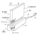
以下、本発明の実施の形態について図面を参照して説明する。図1は本発明の実施の形態に係る非接触充電式電子機器と、その電子機器を充電するための非接触充電器とを示した斜視図である。本発明は、様々な種類の非接触充電式電子機器に適用可能であり、例えば、家庭用コードレス電話機、携帯電話機、PHS、PDA等の小型ポータブル電子機器などにも適用でき、更にその他の電子機器にも適用可能である。図1に示した非接触充電式電子機器10は、それら数多くの電子機器を代表するものである。 Hereinafter, embodiments of the present invention will be described with reference to the drawings. FIG. 1 is a perspective view showing a non-contact rechargeable electronic device according to an embodiment of the present invention and a non-contact charger for charging the electronic device. The present invention can be applied to various types of non-contact rechargeable electronic devices, such as home-use cordless telephones, mobile phones, small portable electronic devices such as PHS and PDA, and other electronic devices. It is also applicable to. The non-contact rechargeable
非接触充電式電子機器10は、扁平な略々直方体の形状の筐体12を備えており、この筐体12は、非金属材料で形成された筐体部分である非金属筐体部分14と、金属材料で形成された筐体部分である金属筐体部分16とを含んでいる。非金属筐体部分14の材料としては、例えばABS樹脂をはじめとする様々なプラスチック材料を使用することができる。具体的にいかなるプラスチック材料を用いるかは、製作上及び使用上の要求条件を考慮して決定すればよい。金属筐体部分16は、鋳造品として製作してもよく、或いは、金属板に塑性加工を施して製作してもよく、更には、それらを組合せて製作してもよい。また、その材料としては、マグネシウム合金やアルミニウムなどを使用することができ、更にその他の金属材料を使用することも可能である。非金属筐体部分14と金属筐体部分16とのいずれも、単一の部材として製作してもよく、複数の部材を組合せて製作してもよい。また、図示例では、筐体12の全体のうち、1箇所だけを非金属筐体部分14としているが、筐体12が、2箇所以上の非金属筐体部分を含む構成としてもよい。金属筐体部分16についても同様であり、筐体12が、2箇所以上の金属筐体部分を含む構成としてもよい。 The non-contact rechargeable
非接触充電器20は、細長い略々直方体の形状の筐体22を備えており、この筐体22の上面には、充電時に電子機器10の筐体12の側縁部を嵌合するための溝24が設けられている。筐体22は、プラスチック材料で製作されている。充電器20は、電磁誘導により電力を供給するための1次コイル26を備えており、この1次コイル26は筐体22の中に内蔵されている。充電器20の筐体22の中には更に、1次コイル26に高周波電流を流すための電子回路(不図示)が内蔵されている。この電子回路は、公知のものであり、筐体22から延出するコード28の先端のプラグ30を介して電灯線から受取る交流電力を、高周波電流に変換して、1次コイル26に供給するものである。 The
電子機器10の筐体12は、充電器20の1次コイルと電磁結合して電力を受取る2次コイル32と、この2次コイル32が受取った電力を蓄積する2次電池(不図示)と、この2次電池に蓄積された電力を使用する電子回路(不図示)とを囲繞している。電子機器10の電子回路には、2次コイル32に誘起された高周波電流を整流して2次電池に充電するための回路も含まれており、そのような回路は公知である。 The
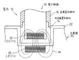
図2は、図1の2−2線に沿った断面図であり、充電器20の1次コイル26と電子機器10の2次コイル32とを示した図である。充電時には、ユーザが、電子機器10の筐体12の側縁部を、充電器20の溝24に嵌合させるようにして、電子機器10を充電器20上に載置する。これによって、図2に示したように、充電器20の筐体22内の一次コイル26と、電子機器10の筐体12内の2次コイル32とが、互いに近接し、しかもそれらコイル26、32の軸心どうしが略々一致するように位置付けられる。 FIG. 2 is a cross-sectional view taken along line 2-2 in FIG. 1 and shows the
図2に示したように、電子機器10の筐体12の全体のうち、2次コイル32の近傍にあって、1次コイル26と2次コイル32とを電磁結合する磁束Mが鎖交する部分は、非金属筐体部分14から成るものとしている。そのため、磁束Mによって筐体12に渦電流が発生するということがない。また、図示例においては、磁束Mが鎖交する部分と、その近傍の部分だけを、非金属筐体部分14から成るものとし、それ以外の部分を、金属筐体部分16から成るものとしている。そして、金属筐体部分16が、筐体12の内部で発生する熱の大部分を、この金属筐体部分14の表面を介して筐体12の外部へ放散するのに十分な表面積を有するようにしてあり、これによって、電子機器10内で発生する熱を効率的に筐体12外に放散して、電子機器10内の部品温度を低く抑えられるようにしている。 As shown in FIG. 2, the magnetic flux M that electromagnetically couples the
図3は、図2と同様の断面図であり、図1及び図2に示した実施の形態の第1の変更形態に係る非接触充電式電子機器を示した図である。図4は、図3の非接触充電式電子機器の非金属筐体部分、2次コイル、及び伝熱材料層を示した分解斜視図である。尚、図3及び図4において、図2に示した構成要素と同一ないし対応する構成要素には、図2に使用したものと同じ参照符号を付してある。また、図3の非接触充電式電子機器のうち、図1及び図2に示した非接触充電式電子機器と同一構成の部分については説明を省略する。 FIG. 3 is a cross-sectional view similar to FIG. 2 and is a view showing a non-contact rechargeable electronic device according to a first modification of the embodiment shown in FIGS. 1 and 2. FIG. 4 is an exploded perspective view showing a non-metallic housing part, a secondary coil, and a heat transfer material layer of the non-contact rechargeable electronic device of FIG. 3 and 4, the same or corresponding components as those shown in FIG. 2 are denoted by the same reference numerals as those used in FIG. In addition, in the non-contact rechargeable electronic device of FIG. 3, the description of the same configuration as the non-contact rechargeable electronic device shown in FIGS. 1 and 2 is omitted.
図3にその一部分を断面図で示した非接触充電式電子機器40は、伝熱材料層42を備えており、この伝熱材料層42は、2次コイル32の上面から、非金属筐体部分12に隣接している金属筐体部分14の縁部に亘って設けられている。伝熱材料層42は、2次コイル32と金属筐体部分16とを熱的に接続して、充電時に2次コイル32が発生する熱を金属筐体部分16へ伝達する伝熱手段として機能するものであり、これによって、2次コイル32が発生する熱を、金属筐体部分16の表面を介して筐体12の外部へ放散し得るようにしている。 A non-contact rechargeable
伝熱材料層42は、非導電性と良好な熱伝導性とを備えた材料から成り、好適に使用し得る材料には、例えば、シート状熱伝導ゲル、ペースト状熱伝導ゲル、熱伝導性樹脂などがある。伝熱材料層42は、非導電性材料であるため、1次コイル26と2次コイル32とを電磁結合する磁束Mが鎖交しても渦電流は発生せず、従って、電磁的な干渉によって充電効率を低下させるおそれがない。シート状熱伝導ゲルの具体例としては、東京都港区に所在の株式会社ジェルテックの製品である「COH-1002」や「COH-4000」、それに、東京都品川区に所在のソニーケミカル株式会社の製品である「O2C97」などがある。また、ペースト状熱伝導ゲルの具体例としては、株式会社ジェルテックの製品である「DP-100」や「DP-200」などがある。使用可能な熱伝導性樹脂にも様々なものがあるが、伝熱手段として用いるものであるため、熱可塑性樹脂よりも、熱硬化性樹脂のうちから適当なものを選択することが好ましい。 The heat
図5は、図2と同様の断面図であり、図1及び図2に示した実施の形態の第2の変更形態に係る非接触充電式電子機器を示した図である。図6は、図5の非接触充電式電子機器の金属製伝熱部材の斜視図である。尚、図5において、図2に示した構成要素と同一ないし対応する構成要素には、図2に使用したものと同じ参照符号を付してある。また、図5の非接触充電式電子機器のうち、図1及び図2に示した非接触充電式電子機器と同一構成の部分については説明を省略する。 FIG. 5 is a cross-sectional view similar to FIG. 2 and is a view showing a non-contact rechargeable electronic device according to a second modification of the embodiment shown in FIGS. 1 and 2. 6 is a perspective view of a metal heat transfer member of the non-contact rechargeable electronic device of FIG. In FIG. 5, the same or corresponding components as those shown in FIG. 2 are denoted by the same reference numerals as those used in FIG. Further, in the non-contact rechargeable electronic device of FIG. 5, the description of the same configuration as the non-contact rechargeable electronic device shown in FIGS. 1 and 2 is omitted.
図5にその一部分を断面図で示した電子機器50は、薄い金属板を組合せてT字形に形成した金属製伝熱部材52を備えている。図6に示したように、金属製伝熱部材52は、2次コイル32の軸心を含む2次コイル32の対象面に沿って、この2次コイル32の近傍に延在する平板状部分54と、この平板状部分54の2次コイル32から離隔した側の端部と、金属筐体部分16とを接続する接続部分56とで構成されている。接続部分56と金属筐体部分16とは、接続部分56を構成している金属板の弾性によって当接しており、それによって金属製伝熱部材52から金属筐体部分16への伝熱を可能にしている。電子機器50は更に、2次コイル32の上面から金属製伝熱部材52の平板状部分54の側面に亘って設けられた伝熱材料層58を備えている。 5 includes a metal
伝熱材料層58は、2次コイル32と金属製伝熱部材52とを熱的に接続して、充電時に2次コイル32が発生する熱を金属製伝熱部材52へ伝達する中間伝熱手段として機能するものである。そして、金属製伝熱部材52と伝熱材料層58との組合せによって、充電時に2次コイル32が発生する熱を金属筐体部分16へ伝達する伝熱手段が構成されている。これによって、2次コイル32が発生する熱を、金属筐体部分16の表面を介して筐体12の外部へ放散し得るようにしている。 The heat
伝熱材料層58は、非導電性と良好な熱伝導性とを備えた材料から成り、その材料としては、伝熱材料層42の材料として上に例示した様々な材料を使用することができる。 The heat
金属製伝熱部材52は、良好な熱伝導性、弾性、及び適当な強度を備えた金属の板材で製作するとよい。一般的に、強度条件を満足し得る程度の厚さを有する金属板であれば、熱伝導性に関する条件も満足される。弾性を備えるという条件は、金属製伝熱部材52の接続部分56と金属筐体部分16との間の接触面の伝熱性能を良好に維持するために必要なものである。具体的な例を挙げるならば、金属製伝熱部材52の材料としては、例えば燐青銅やステンレスなどの薄板を使用することができる。 The metal
金属製伝熱部材52のうち、接続部材56は、2次コイル32から十分に離隔しているため、1次コイル26と2次コイル32とを電磁結合する磁束Mが鎖交することがなく、従って、磁束Mによって渦電流が発生するということがない。また、平板状部分54は、薄板状であって、しかも、2次コイル32の軸心を含む2次コイル32の対象面に沿って延在しているため、鎖交する磁束Mの磁力線の方向が板面に平行になることから、渦電流は殆ど発生しない。従って、金属製伝熱部材52は、電磁的な干渉によって充電効率を低下させるおそれがなく、更に、伝熱材料層58も、非導電性材料であるため、電磁的な干渉によって充電効率を低下させるおそれがない。 Among the metal
10……非接触充電式電子機器、12……筐体、14……非金属筐体部分、16……金属筐体部分、20……非接触充電器、22……筐体、26……1次コイル、32……2次コイル、40……非接触充電式電子機器、42……伝熱材料層、50……非接触充電式電子機器、52……金属製伝熱部材、58……伝熱材料層。
DESCRIPTION OF
Claims (6)
Translated fromJapanese前記筐体が、非金属材料で形成された筐体部分である非金属筐体部分と、金属材料で形成された筐体部分である金属筐体部分とを含んでおり、
前記筐体の全体のうち、前記2次コイルの近傍にあって前記1次コイルと前記2次コイルとを電磁結合する磁束が鎖交する部分が前記非金属筐体部分から成り、
前記金属筐体部分が、前記筐体の内部で発生する熱の大部分を該金属筐体部分の表面を介して前記筐体の外部へ放散するのに十分な表面積を有する、
ことを特徴とする非接触充電式電子機器。A secondary coil that receives power by electromagnetically coupling with the primary coil of the non-contact charger including a primary coil for supplying power by electromagnetic induction, and a secondary that stores the power received by the secondary coil In a non-contact rechargeable electronic device comprising: a battery; an electronic circuit that uses power stored in the secondary battery; and a casing that surrounds the secondary coil, the secondary battery, and the electronic circuit.
The housing includes a non-metallic housing portion that is a housing portion formed of a non-metallic material, and a metal housing portion that is a housing portion formed of a metal material,
Of the entire casing, the non-metallic casing portion is a portion in the vicinity of the secondary coil where a magnetic flux that electromagnetically couples the primary coil and the secondary coil is linked.
The metal housing portion has a surface area sufficient to dissipate most of the heat generated within the housing to the outside of the housing through the surface of the metal housing portion;
A non-contact rechargeable electronic device.
前記筐体が、非金属材料で形成された筐体部分である非金属筐体部分と、金属材料で形成された筐体部分である金属筐体部分とを含んでおり、
前記筐体の全体のうち、前記2次コイルの近傍にあって前記1次コイルと前記2次コイルとを電磁結合する磁束が鎖交する部分が前記非金属筐体部分から成り、
前記2次コイルと前記金属筐体部分とを熱的に接続して前記2次コイルが発生する熱を前記金属筐体部分へ伝達する伝熱手段を備え、前記2次コイルが発生する熱を前記金属筐体部分の表面を介して前記筐体の外部へ放散するようにした、
ことを特徴とする非接触充電式電子機器。A secondary coil that receives power by electromagnetically coupling with the primary coil of the non-contact charger including a primary coil for supplying power by electromagnetic induction, and a secondary that stores the power received by the secondary coil In a non-contact rechargeable electronic device comprising: a battery; an electronic circuit that uses power stored in the secondary battery; and a casing that surrounds the secondary coil, the secondary battery, and the electronic circuit.
The housing includes a non-metallic housing portion that is a housing portion formed of a non-metallic material, and a metal housing portion that is a housing portion formed of a metal material,
Of the entire casing, the non-metallic casing portion is a portion in the vicinity of the secondary coil where a magnetic flux that electromagnetically couples the primary coil and the secondary coil is linked.
Heat transfer means is provided for thermally connecting the secondary coil and the metal casing portion to transmit heat generated by the secondary coil to the metal casing portion, and heat generated by the secondary coil is provided. Dissipate to the outside of the housing through the surface of the metal housing portion,
A non-contact rechargeable electronic device.
The intermediate heat transfer means is made of a material having non-conductivity and good heat conductivity, and the material is selected from the group consisting of a sheet-like heat conductive gel, a paste-like heat conductive gel, and a heat conductive resin. The contactless rechargeable electronic device according to claim 5, wherein the material is a selected material.
Priority Applications (1)
| Application Number | Priority Date | Filing Date | Title |
|---|---|---|---|
| JP2003337390AJP2005110357A (en) | 2003-09-29 | 2003-09-29 | Noncontact charging electronic apparatus |
Applications Claiming Priority (1)
| Application Number | Priority Date | Filing Date | Title |
|---|---|---|---|
| JP2003337390AJP2005110357A (en) | 2003-09-29 | 2003-09-29 | Noncontact charging electronic apparatus |
Publications (1)
| Publication Number | Publication Date |
|---|---|
| JP2005110357Atrue JP2005110357A (en) | 2005-04-21 |
Family
ID=34533225
Family Applications (1)
| Application Number | Title | Priority Date | Filing Date |
|---|---|---|---|
| JP2003337390APendingJP2005110357A (en) | 2003-09-29 | 2003-09-29 | Noncontact charging electronic apparatus |
Country Status (1)
| Country | Link |
|---|---|
| JP (1) | JP2005110357A (en) |
Cited By (4)
| Publication number | Priority date | Publication date | Assignee | Title |
|---|---|---|---|---|
| EP1944623A2 (en) | 2007-01-12 | 2008-07-16 | Konica Minolta Medical & Graphic, Inc. | Radiation image detecting device and radiation image radiographing system |
| EP1962305A2 (en) | 2007-02-20 | 2008-08-27 | Seiko Epson Corporation | Coil unit, method of manufacturing the same, and electronic instrument |
| EP2017860A2 (en) | 2007-07-20 | 2009-01-21 | Seiko Epson Corporation | Coil unit and electronic instrument |
| WO2013038591A1 (en)* | 2011-09-16 | 2013-03-21 | パナソニック株式会社 | Power-reception device, power-transmission device, and power-transfer device |
- 2003
- 2003-09-29JPJP2003337390Apatent/JP2005110357A/enactivePending
Cited By (6)
| Publication number | Priority date | Publication date | Assignee | Title |
|---|---|---|---|---|
| EP1944623A2 (en) | 2007-01-12 | 2008-07-16 | Konica Minolta Medical & Graphic, Inc. | Radiation image detecting device and radiation image radiographing system |
| EP1962305A2 (en) | 2007-02-20 | 2008-08-27 | Seiko Epson Corporation | Coil unit, method of manufacturing the same, and electronic instrument |
| US7750783B2 (en) | 2007-02-20 | 2010-07-06 | Seiko Epson Corporation | Electronic instrument including a coil unit |
| EP2017860A2 (en) | 2007-07-20 | 2009-01-21 | Seiko Epson Corporation | Coil unit and electronic instrument |
| US8541977B2 (en) | 2007-07-20 | 2013-09-24 | Seiko Epson Corporation | Coil unit and electronic instrument |
| WO2013038591A1 (en)* | 2011-09-16 | 2013-03-21 | パナソニック株式会社 | Power-reception device, power-transmission device, and power-transfer device |
Similar Documents
| Publication | Publication Date | Title |
|---|---|---|
| US6396241B1 (en) | Inductive charging system employing a fluid-cooled transformer coil and transmission cable | |
| CN101841173B (en) | Charging system | |
| JP4508266B2 (en) | Coil unit and electronic device using the same | |
| JP2010245323A (en) | Coil unit and electronic equipment | |
| KR102644869B1 (en) | Wireless power transmission module and electronic device having the same | |
| JP5327329B2 (en) | Battery pack | |
| US9479007B1 (en) | Induction charging system | |
| CN103222153B (en) | Power supply device and power transmission system | |
| JP2012010533A (en) | Power transmission system, and power supply device and portable apparatus therefor | |
| TW201527932A (en) | Mobile terminal | |
| US20060214628A1 (en) | Induction charger assembly and electronic device employing the same | |
| US9667075B2 (en) | Wireless charging device and method using the same | |
| JP2000341885A (en) | Noncontact power transmission device and manufacture thereof | |
| CN110892493A (en) | Wireless power transmitting device for vehicle | |
| US12316130B2 (en) | Wireless charging apparatus | |
| JP5874844B2 (en) | Wireless power transmission system | |
| JP2005110357A (en) | Noncontact charging electronic apparatus | |
| US11601003B2 (en) | Universal wireless charging receiver | |
| TWI612748B (en) | A wireless charger, a computing device, and a charging system | |
| JP4915578B2 (en) | Contactless power supply | |
| US20160268814A1 (en) | Wireless power transfer for mobile devices | |
| JP2009005472A (en) | Non-contact power transmission equipment | |
| KR100698219B1 (en) | Contactless charging device | |
| CN208423894U (en) | Wireless charger | |
| CN217692807U (en) | Wireless charging module, wireless charging transmitting base station and wireless charging receiving terminal |