JP2005110228A - Secure communication method, transmitter, and receiver - Google Patents
Secure communication method, transmitter, and receiverDownload PDFInfo
- Publication number
- JP2005110228A JP2005110228AJP2004258919AJP2004258919AJP2005110228AJP 2005110228 AJP2005110228 AJP 2005110228AJP 2004258919 AJP2004258919 AJP 2004258919AJP 2004258919 AJP2004258919 AJP 2004258919AJP 2005110228 AJP2005110228 AJP 2005110228A
- Authority
- JP
- Japan
- Prior art keywords
- signal
- transmission
- antenna
- channel estimation
- symbol
- Prior art date
- Legal status (The legal status is an assumption and is not a legal conclusion. Google has not performed a legal analysis and makes no representation as to the accuracy of the status listed.)
- Pending
Links
Images


Classifications
- H—ELECTRICITY
- H04—ELECTRIC COMMUNICATION TECHNIQUE
- H04B—TRANSMISSION
- H04B7/00—Radio transmission systems, i.e. using radiation field
- H04B7/02—Diversity systems; Multi-antenna system, i.e. transmission or reception using multiple antennas
- H04B7/04—Diversity systems; Multi-antenna system, i.e. transmission or reception using multiple antennas using two or more spaced independent antennas
- H04B7/06—Diversity systems; Multi-antenna system, i.e. transmission or reception using multiple antennas using two or more spaced independent antennas at the transmitting station
- H04B7/0602—Diversity systems; Multi-antenna system, i.e. transmission or reception using multiple antennas using two or more spaced independent antennas at the transmitting station using antenna switching
- H04B7/0604—Diversity systems; Multi-antenna system, i.e. transmission or reception using multiple antennas using two or more spaced independent antennas at the transmitting station using antenna switching with predefined switching scheme
- H—ELECTRICITY
- H04—ELECTRIC COMMUNICATION TECHNIQUE
- H04B—TRANSMISSION
- H04B7/00—Radio transmission systems, i.e. using radiation field
- H04B7/02—Diversity systems; Multi-antenna system, i.e. transmission or reception using multiple antennas
- H04B7/04—Diversity systems; Multi-antenna system, i.e. transmission or reception using multiple antennas using two or more spaced independent antennas
- H04B7/06—Diversity systems; Multi-antenna system, i.e. transmission or reception using multiple antennas using two or more spaced independent antennas at the transmitting station
- H04B7/0602—Diversity systems; Multi-antenna system, i.e. transmission or reception using multiple antennas using two or more spaced independent antennas at the transmitting station using antenna switching
- H04B7/0608—Antenna selection according to transmission parameters
- H—ELECTRICITY
- H04—ELECTRIC COMMUNICATION TECHNIQUE
- H04B—TRANSMISSION
- H04B7/00—Radio transmission systems, i.e. using radiation field
- H04B7/02—Diversity systems; Multi-antenna system, i.e. transmission or reception using multiple antennas
- H04B7/04—Diversity systems; Multi-antenna system, i.e. transmission or reception using multiple antennas using two or more spaced independent antennas
- H04B7/06—Diversity systems; Multi-antenna system, i.e. transmission or reception using multiple antennas using two or more spaced independent antennas at the transmitting station
- H04B7/0686—Hybrid systems, i.e. switching and simultaneous transmission
- H04B7/0689—Hybrid systems, i.e. switching and simultaneous transmission using different transmission schemes, at least one of them being a diversity transmission scheme
- H—ELECTRICITY
- H04—ELECTRIC COMMUNICATION TECHNIQUE
- H04B—TRANSMISSION
- H04B7/00—Radio transmission systems, i.e. using radiation field
- H04B7/02—Diversity systems; Multi-antenna system, i.e. transmission or reception using multiple antennas
- H04B7/04—Diversity systems; Multi-antenna system, i.e. transmission or reception using multiple antennas using two or more spaced independent antennas
- H04B7/06—Diversity systems; Multi-antenna system, i.e. transmission or reception using multiple antennas using two or more spaced independent antennas at the transmitting station
- H04B7/0686—Hybrid systems, i.e. switching and simultaneous transmission
- H04B7/0691—Hybrid systems, i.e. switching and simultaneous transmission using subgroups of transmit antennas
- H—ELECTRICITY
- H04—ELECTRIC COMMUNICATION TECHNIQUE
- H04L—TRANSMISSION OF DIGITAL INFORMATION, e.g. TELEGRAPHIC COMMUNICATION
- H04L25/00—Baseband systems
- H04L25/02—Details ; arrangements for supplying electrical power along data transmission lines
- H04L25/0202—Channel estimation
- H04L25/0204—Channel estimation of multiple channels
- H—ELECTRICITY
- H04—ELECTRIC COMMUNICATION TECHNIQUE
- H04L—TRANSMISSION OF DIGITAL INFORMATION, e.g. TELEGRAPHIC COMMUNICATION
- H04L27/00—Modulated-carrier systems
- H04L27/18—Phase-modulated carrier systems, i.e. using phase-shift keying
- H—ELECTRICITY
- H04—ELECTRIC COMMUNICATION TECHNIQUE
- H04L—TRANSMISSION OF DIGITAL INFORMATION, e.g. TELEGRAPHIC COMMUNICATION
- H04L27/00—Modulated-carrier systems
- H04L27/26—Systems using multi-frequency codes
- H04L27/2601—Multicarrier modulation systems
- H—ELECTRICITY
- H04—ELECTRIC COMMUNICATION TECHNIQUE
- H04L—TRANSMISSION OF DIGITAL INFORMATION, e.g. TELEGRAPHIC COMMUNICATION
- H04L25/00—Baseband systems
- H04L25/02—Details ; arrangements for supplying electrical power along data transmission lines
- H04L25/0202—Channel estimation
- H04L25/0224—Channel estimation using sounding signals
- H—ELECTRICITY
- H04—ELECTRIC COMMUNICATION TECHNIQUE
- H04L—TRANSMISSION OF DIGITAL INFORMATION, e.g. TELEGRAPHIC COMMUNICATION
- H04L27/00—Modulated-carrier systems
- H04L27/26—Systems using multi-frequency codes
- H04L27/2601—Multicarrier modulation systems
- H04L27/2602—Signal structure
- H04L27/261—Details of reference signals
Landscapes
- Engineering & Computer Science (AREA)
- Computer Networks & Wireless Communication (AREA)
- Signal Processing (AREA)
- Power Engineering (AREA)
- Radio Transmission System (AREA)
- Mobile Radio Communication Systems (AREA)
Abstract
Translated fromJapaneseDescription
Translated fromJapanese本発明は、無線通信を行う際に送信装置と受信装置との間でセキュリティを確保するセキュア通信の通信方法及びそれを用いた通信装置に関する。 The present invention relates to a secure communication method for ensuring security between a transmission device and a reception device when performing wireless communication, and a communication device using the same.
近年、携帯端末の普及等に伴い、無線通信を行う際に送信装置と受信装置との間でのセキュリティの向上が要求されている。このセキュリティを確保するセキュア通信の従来方法の一例(特許文献1)について、図19を用いて説明する。 In recent years, with the spread of mobile terminals and the like, it is required to improve security between a transmission device and a reception device when performing wireless communication. An example of a conventional secure communication method (Patent Document 1) for ensuring security will be described with reference to FIG.
図19において、送信装置10は、変調部11と、無線部12と、送信アンテナ13とを有する。変調部11は、送信ディジタル信号を入力し、これを変調して送信ベースバンド信号を生成し、これを無線部12に出力する。無線部12は、送信ベースバンド信号を入力し、これをアップコンバートして送信信号を生成し、これを送信アンテナ13から無線送信する。 In FIG. 19, the
一方、受信装置50は、受信アンテナ51と、送信アンテナ52と、無線部53と、妨害波発生部54と、妨害波加工部55と、加算部56と、復調部57とを有する。無線部53は、受信アンテナ51で受信された受信信号を入力し、これをダウンコンバートして受信ベースバンド信号を生成し、これを加算部56に出力する。また、無線部53は、妨害波発生部54が発生する妨害波信号を入力し、これをアップコンバートして送信妨害波信号を生成し、これを送信アンテナ52から無線送信する。この結果、送信アンテナ13から無線送信された送信信号と送信アンテナ52から無線送信された送信妨害波信号とが加算された信号が、受信アンテナ51で受信される受信信号となる。 On the other hand, the
妨害波加工部55は、妨害波発生部54が発生する妨害波信号を入力し、これに対して位相反転処理及び減衰処理を行って加工妨害波信号を生成し、これを加算部56に出力する。 The interference
加算部56は、受信ベースバンド信号及び加工妨害波信号を入力し、これらを加算する。これにより、受信ベースバンド信号から妨害波信号が除去され、妨害波除去信号が生成される。加算部56は、妨害波除去信号を復調部57に出力する。復調部57は、妨害波除去信号を入力し、これを復調して受信ディジタル信号を生成する。 The
このように、従来技術では、受信装置から妨害波を発生し、受信装置内で妨害波を除去することでセキュア通信を実現している。
しかしながら、従来のセキュア通信では、送信装置が1本の送信アンテナから信号を送信しているため、物理的に電波を受信することができる。したがって、従来のセキュア通信では、通信のセキュア性に限界がある。 However, in the conventional secure communication, since the transmission device transmits a signal from one transmission antenna, it is possible to physically receive radio waves. Therefore, the conventional secure communication has a limit in the security of communication.
本発明はかかる点に鑑みてなされたものであり、複数のアンテナから信号を送信し、従来の方式よりも通信のセキュア性を向上させることができるセキュア通信方法および送信装置、受信装置を提供することを目的とする。 The present invention has been made in view of the above points, and provides a secure communication method, a transmission device, and a reception device capable of transmitting signals from a plurality of antennas and improving communication security as compared with a conventional method. For the purpose.
本発明のセキュア通信方法は、複数の送信アンテナを備えた送信装置が、所定のアンテナ変更パターンに基づき前記送信アンテナを切替えて信号を無線送信し、受信装置が前記送信装置から無線送信された信号に対して前記送信装置と同一のアンテナ変更パターンを用いてチャネル推定を行いデータ復調する方法をとる。 According to the secure communication method of the present invention, a transmission device having a plurality of transmission antennas switches a transmission antenna based on a predetermined antenna change pattern and wirelessly transmits a signal, and a reception device wirelessly transmits the signal from the transmission device. On the other hand, a data demodulation method is performed by performing channel estimation using the same antenna change pattern as that of the transmission apparatus.
本発明のセキュア通信方法は、複数の送信アンテナを有する送信装置において、ディジタルデータにチャネル推定用のシンボルを挿入して送信ディジタル信号を生成する工程と、前記送信ディジタル信号をアップコンバートして送信信号を生成する工程と、所定のアンテナ変更パターンに従ってアンテナを選択する工程と、選択したアンテナを用いて前記複数の送信信号を無線送信する工程と、を具備し、前記送信装置と同一のアンテナ変更パターンを記憶する受信装置において、受信した前記送信装置からの信号をダウンコンバートして受信ディジタル信号を生成する工程と、前記送信装置が送信アンテナを切替えるタイミングに同期して前記受信ディジタル信号からデータシンボルとチャネル推定用のシンボルを分離する工程と、前記アンテナ変更パターンに基づき前記分離されたチャネル推定用のシンボルを用いてチャネル推定を行う工程と、チャネル推定値に基づいて前記データシンボルを復調する工程と、を具備する方法をとる。 The secure communication method of the present invention includes a step of generating a transmission digital signal by inserting a channel estimation symbol into digital data in a transmission apparatus having a plurality of transmission antennas, and up-converting the transmission digital signal to obtain a transmission signal. Generating the same antenna changing pattern as that of the transmitting apparatus, the step of selecting an antenna according to a predetermined antenna changing pattern, and the step of wirelessly transmitting the plurality of transmission signals using the selected antenna In the receiving device storing the received signal, the step of down-converting the received signal from the transmitting device to generate a received digital signal, and the data symbol from the received digital signal in synchronization with the timing at which the transmitting device switches the transmitting antenna, Separating a symbol for channel estimation; and Take a step of performing channel estimation using the symbol for the separated channel estimation based on the antenna change pattern, a step of demodulating the data symbols based on the channel estimates, the method comprising the.
本発明のセキュア通信方法は、複数の送信アンテナを備えた送信装置が、所定の信号配置パターンに基づき送信信号を無線送信し、受信装置が前記送信装置から無線送信された信号に対して前記送信装置と同一の信号配置パターンを用いてデータ復調する方法をとる。 According to the secure communication method of the present invention, a transmission device including a plurality of transmission antennas wirelessly transmits a transmission signal based on a predetermined signal arrangement pattern, and a reception device transmits the transmission signal with respect to a signal wirelessly transmitted from the transmission device. A method of demodulating data using the same signal arrangement pattern as the apparatus is adopted.
本発明の送信装置は、複数の送信アンテナと、ディジタルデータにチャネル推定用のシンボルを挿入して複数の送信ディジタル信号を生成するフレーム構成手段と、前記送信ディジタル信号をアップコンバートして送信信号を生成する無線手段と、通信相手の受信装置と共通するアンテナ変更パターンに従ってアンテナ変更を指示するアンテナ変更手段と、前記アンテナ変更手段の指示に従って選択した送信アンテナを用いて前記送信信号を無線送信するアンテナ選択手段と、を具備する構成をとる。 The transmission apparatus of the present invention includes a plurality of transmission antennas, frame configuration means for generating a plurality of transmission digital signals by inserting symbols for channel estimation into digital data, and a transmission signal obtained by up-converting the transmission digital signals. Radio means for generating, antenna changing means for instructing antenna change in accordance with an antenna change pattern common to a communication partner receiving apparatus, and an antenna for wirelessly transmitting the transmission signal using a transmission antenna selected in accordance with an instruction from the antenna changing means And a selection unit.
本発明の送信装置は、複数の送信アンテナと、ディジタルデータから複数の送信信号を生成する信号生成手段と、パイロット信号を生成するパイロット信号生成手段と、前記複数の送信信号を所定の信号配置パターンに従って配置し前記パイロット信号を挿入する信号形成手段と、通信相手の受信装置と共通する信号配置パターンに従って信号配置を前記信号形成手段に指示する信号配置手段と、前記信号形成手段にて配置された信号をアップコンバートして送信信号を生成する無線手段と、を具備する構成をとる。 The transmission apparatus of the present invention includes a plurality of transmission antennas, a signal generation unit that generates a plurality of transmission signals from digital data, a pilot signal generation unit that generates a pilot signal, and the plurality of transmission signals in a predetermined signal arrangement pattern. Arranged in accordance with the signal forming means for inserting the pilot signal, signal arranging means for instructing the signal forming means in accordance with a signal arrangement pattern common to the receiving apparatus of the communication partner, and arranged in the signal forming means And radio means for generating a transmission signal by up-converting the signal.
本発明の受信装置は、上記送信装置から送信された信号を受信しダウンコンバートして受信ディジタル信号を生成する無線手段と、前記送信装置が送信アンテナを切替えるタイミングに同期して前記受信ディジタル信号からデータシンボルとチャネル推定用のシンボルを分離する分離手段と、前記送信装置と共通するアンテナ変更パターンに基づいて前記分離されたチャネル推定用のシンボルを用いてチャネル推定を行うチャネル推定手段と、チャネル推定値に基づいて前記データシンボルを復調する信号処理手段と、を具備する構成をとる。 The receiving apparatus of the present invention includes a radio unit that receives a signal transmitted from the transmitting apparatus and down-converts to generate a received digital signal, and the received digital signal in synchronization with a timing at which the transmitting apparatus switches a transmitting antenna. Separation means for separating data symbols and channel estimation symbols, channel estimation means for performing channel estimation using the separated channel estimation symbols based on an antenna change pattern common to the transmission apparatus, and channel estimation Signal processing means for demodulating the data symbol based on the value.
本発明の受信装置は、上記送信装置から送信された信号を受信しダウンコンバートして受信ベースバンド信号を生成する無線手段と、前記送信装置が信号配置パターンを切り替えるタイミングに同期して前記送信装置と共通する信号配置パターンに基づいて前記分離されたチャネル推定用のシンボルを用いてチャネル推定を行うチャネル推定手段と、前記送信装置と共通する信号配置パターンとチャネル推定値とに基づいて前記データシンボルを復調する信号処理手段と、を具備する構成をとる。 The receiving apparatus of the present invention includes a radio unit that receives a signal transmitted from the transmitting apparatus and down-converts to generate a received baseband signal, and the transmitting apparatus in synchronization with a timing at which the transmitting apparatus switches a signal arrangement pattern. Channel estimation means for performing channel estimation using the separated symbol for channel estimation based on a common signal arrangement pattern, and the data symbol based on a signal arrangement pattern and a channel estimation value common to the transmitter And a signal processing means for demodulating the signal.
本発明によれば、送信装置が所定のパターンに基づき送信アンテナを切り替えることにより、送信信号の伝搬路を切り替えることができる。一方で、受信装置が送信装置と同一のパターンを用いてチャネル推定を行うことにより受信信号を復調することができる。この結果、たとえ第三者に送信アンテナ切り替え前に電波を傍受されていたとしても、送信アンテナ切り替えによりその後に電波を傍受されることを防ぐことができ、通信のセキュア性を向上させることができる。 ADVANTAGE OF THE INVENTION According to this invention, the transmission path of a transmission signal can be switched because a transmission apparatus switches a transmission antenna based on a predetermined pattern. On the other hand, the received signal can be demodulated when the receiving apparatus performs channel estimation using the same pattern as the transmitting apparatus. As a result, even if a radio wave is intercepted by a third party before the transmission antenna is switched, it is possible to prevent the radio wave from being intercepted after the transmission antenna is switched, and the security of communication can be improved. .
本発明の骨子は、複数の送信アンテナを有する送信装置が所定のパターンに基づき送信アンテナを切り替えて信号を送信し、受信装置が送信装置の送信アンテナを切替えるタイミングに同期して送信装置と同一のパターンを用いてチャネル推定を行うことである。 The essence of the present invention is that a transmission apparatus having a plurality of transmission antennas transmits a signal by switching the transmission antenna based on a predetermined pattern, and is the same as the transmission apparatus in synchronization with the timing at which the reception apparatus switches the transmission antenna of the transmission apparatus. Channel estimation is performed using a pattern.
以下、本発明の実施の形態について、添付図面を参照して詳細に説明する。 Hereinafter, embodiments of the present invention will be described in detail with reference to the accompanying drawings.
(実施の形態1)
実施の形態1では、3本の送信アンテナを有する送信装置が2種類の信号を送信する際に送信アンテナを切り替え、2本の受信アンテナを有する受信装置が複数チャネルからの受信信号を分離し復調する場合について説明する。また、本実施の形態では、マルチキャリア方式の例としてOFDM(Orthogonal Frequency Division Multiplexing)方式を用いる。(Embodiment 1)
In the first embodiment, when a transmitting apparatus having three transmitting antennas transmits two types of signals, the transmitting antenna is switched, and a receiving apparatus having two receiving antennas separates and demodulates received signals from a plurality of channels. The case where it does is demonstrated. In this embodiment, an OFDM (Orthogonal Frequency Division Multiplexing) scheme is used as an example of the multicarrier scheme.
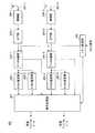
まず、本実施の形態に係る送信装置の構成の一例について、図1のブロック図を用いて説明する。図1において、送信装置100は、フレーム構成部101−1、101−2と、S/P部102−1、102−2と、IDFT部103−1、103−2と、無線部104−1、104−2と、アンテナ変更部105と、アンテナ選択部106と、送信アンテナ107−1〜107−3とを有する。 First, an example of the configuration of the transmission apparatus according to this embodiment will be described with reference to the block diagram of FIG. In FIG. 1, the
フレーム構成部101−1、101−2は、それぞれ、送信ディジタルデータを入力し、送信ディジタルデータにチャネル推定シンボル、ガードシンボルを挿入して送信ディジタル信号を生成し、これをS/P部102−1、102−2に出力する。 Each of frame configuration sections 101-1 and 101-2 receives transmission digital data, inserts a channel estimation symbol and a guard symbol into the transmission digital data, generates a transmission digital signal, and generates this as a S / P section 102- 1 and 102-2.
なお、チャネル推定シンボルは、時間同期、周波数同期、伝送路による歪みを推定するためのシンボルであり、パイロットシンボル、ユニークワード、プリアンブルなどの既知シンボルに相当し、BPSK(Binary Phase Shift Keying)変調された信号が適している。また、ガードシンボルには、通常、ヌルシンボルが挿入される。 The channel estimation symbol is a symbol for estimating time synchronization, frequency synchronization, and distortion due to a transmission path, corresponds to a known symbol such as a pilot symbol, a unique word, and a preamble, and is subjected to BPSK (Binary Phase Shift Keying) modulation. Suitable signal. Also, a null symbol is usually inserted into the guard symbol.
S/P部102−1は、送信ディジタル信号を入力し、直並列変換処理を行ってIDFT部103−1に出力する。S/P部102−2は、送信ディジタル信号を入力し、直並列変換処理を行ってIDFT部103−2に出力する。 S / P section 102-1 receives the transmission digital signal, performs serial-parallel conversion processing, and outputs the result to IDFT section 103-1. S / P section 102-2 receives the transmission digital signal, performs serial / parallel conversion processing, and outputs the result to IDFT section 103-2.
IDFT部103−1は、並列化された送信ディジタル信号を入力し、IDFT変換処理を行って送信ベースバンド信号を生成し、これを無線部104−1に出力する。IDFT部103−2は、並列化された送信ディジタル信号を入力し、IDFT変換処理を行って送信ベースバンド信号を生成し、これを無線部104−2に出力する。なお、IDFT変換処理としてIFFT(Inverse Fast Fourier Transform)が一般に使用される。 The IDFT unit 103-1 receives the parallel transmission digital signal, performs IDFT conversion processing to generate a transmission baseband signal, and outputs this to the radio unit 104-1. The IDFT unit 103-2 receives the parallel transmission digital signal, performs IDFT conversion processing to generate a transmission baseband signal, and outputs this to the radio unit 104-2. Note that IFFT (Inverse Fast Fourier Transform) is generally used as the IDFT conversion process.
無線部104−1は、送信ベースバンド信号を入力し、これをアップコンバートして送信信号(以下、「送信信号A」という)を生成し、これをアンテナ選択部106に出力する。無線部104−2は、送信ベースバンド信号を入力し、これをアップコンバートして送信信号(以下、「送信信号B」という)を生成し、これをアンテナ選択部106に出力する。 Radio section 104-1 receives a transmission baseband signal, up-converts it to generate a transmission signal (hereinafter referred to as “transmission signal A”), and outputs this to
アンテナ変更部105は、アンテナ変更パターンを内部メモリに記憶し、クロック信号を入力する毎にアンテナ変更パターンに従ってアンテナ変更を指示するアンテナ変更信号を生成し、これをアンテナ選択部106に出力する。 The
アンテナ選択部106は、アンテナ変更信号に基づき、送信信号A、送信信号Bの送信アンテナとして、送信アンテナ107−1〜107−3の中から互いに異なる2つを選択し、選択した送信アンテナを用いて送信信号A及び送信信号Bを無線送信する。 The
以上が、本実施の形態に係る送信装置の構成例の説明である。 The above is the description of the configuration example of the transmission device according to the present embodiment.
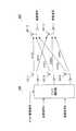
次に、図1に示した送信装置と無線通信を行う本実施の形態に係る受信装置の構成の一例について、図2のブロック図を用いて説明する。図2において、受信装置200は、受信アンテナ201−1、201−2と、無線部202−1、202−2と、DFT部203−1、203−2と、パターン記憶部204と、データ分離部205−1、205−2と、チャネル推定部206−1〜206−4と、信号処理部207とを有する。 Next, an example of the configuration of the reception apparatus according to this embodiment that performs wireless communication with the transmission apparatus illustrated in FIG. 1 will be described with reference to the block diagram of FIG. In FIG. 2, the
無線部202−1は、受信アンテナ201−1に受信された受信信号を入力し、これをダウンコンバートして受信ベースバンド信号を生成し、これをDFT部203−1に出力する。無線部202−2は、受信アンテナ201−2に受信された受信信号を入力し、これをダウンコンバートして受信ベースバンド信号を生成し、これをDFT部203−2に出力する。 Radio section 202-1 receives the received signal received by receiving antenna 201-1, down-converts it to generate a received baseband signal, and outputs this to DFT section 203-1. Radio section 202-2 receives the received signal received by receiving antenna 201-2, down-converts it to generate a received baseband signal, and outputs this to DFT section 203-2.
DFT部203−1は、受信ベースバンド信号を入力し、これに対してDFT変換処理を行ってデータ分離部205−1に出力する。DFT部203−2は、受信ベースバンド信号を入力し、これに対してDFT変換処理を行ってデータ分離部205−2に出力する。なお、DFT変換処理としてFFT(Fast Fourier Transform)が一般に使用される。 The DFT unit 203-1 receives the received baseband signal, performs DFT conversion processing on the received baseband signal, and outputs it to the data separation unit 205-1. The DFT unit 203-2 receives the received baseband signal, performs DFT conversion processing on the received baseband signal, and outputs it to the data separation unit 205-2. Note that FFT (Fast Fourier Transform) is generally used as the DFT transform process.
パターン記憶部204は、図1に示したアンテナ変更部105に記憶されたアンテナ変更パターンと同一のものを内部メモリに記憶し、クロック信号を入力する毎にアンテナ変更パターンに従って送信アンテナを示す送信パターン情報信号を生成し、これをデータ分離部205−1、205−2及び信号処理部207に出力する。 The
データ分離部205−1は、送信パターン情報信号に基づいて、DFT変換処理された受信ベースバンド信号を送信信号Aのチャネル推定シンボル、送信信号Bのチャネル推定シンボル及びデータシンボルに分離し、送信信号Aのチャネル推定シンボルをチャネル推定部206−1に出力し、送信信号Bのチャネル推定シンボルをチャネル推定部206−2に出力し、データシンボルを信号処理部207に出力する。データ分離部205−2は、送信パターン情報信号に基づいて、DFT変換処理された受信ベースバンド信号を送信信号Aのチャネル推定シンボル、送信信号Bのチャネル推定シンボル及びデータシンボルに分離し、送信信号Aのチャネル推定シンボルをチャネル推定部206−3に出力し、送信信号Bのチャネル推定シンボルをチャネル推定部206−4に出力し、データシンボルを信号処理部207に出力する。 Based on the transmission pattern information signal, the data separation unit 205-1 separates the received baseband signal that has been subjected to the DFT conversion process into a channel estimation symbol of the transmission signal A, a channel estimation symbol of the transmission signal B, and a data symbol, and transmits the transmission signal. A channel estimation symbol A is output to channel estimation section 206-1, channel estimation symbol of transmission signal B is output to channel estimation section 206-2, and data symbols are output to signal
チャネル推定部206−1は、受信アンテナ201−1に受信された送信信号Aのチャネル推定シンボルを入力し、送信信号Aの時間同期、周波数同期及び伝送路による歪みの推定の各処理(以下、「チャネル推定」という)を行い、処理結果を示す値であるチャネル推定値を信号処理部207に出力する。チャネル推定部206−2は、受信アンテナ201−1に受信された送信信号Bのチャネル推定シンボルを入力し、送信信号Bのチャネル推定を行い、チャネル推定値を信号処理部207に出力する。 The channel estimation unit 206-1 receives the channel estimation symbol of the transmission signal A received by the reception antenna 201-1, and performs each processing (hereinafter, referred to as “time synchronization”, “frequency synchronization”, and “distortion estimation by transmission path” of the transmission signal A). The channel estimation value that is a value indicating the processing result is output to the
チャネル推定部206−3は、受信アンテナ201−2に受信された送信信号Aのチャネル推定シンボルを入力し、送信信号Aのチャネル推定を行い、チャネル推定値を信号処理部207に出力する。チャネル推定部206−4は、受信アンテナ201−2に受信された送信信号Bのチャネル推定シンボルを入力し、送信信号Bのチャネル推定を行い、チャネル推定値を信号処理部207に出力する。 Channel estimation section 206-3 receives channel estimation symbol of transmission signal A received by reception antenna 201-2, performs channel estimation of transmission signal A, and outputs a channel estimation value to signal
信号処理部207は、チャネル推定値及び送信パターン情報信号を用いてデータシンボルを復調し、受信ディジタルデータを生成する。復調方法の例として、チャネル推定値で構成されるチャネル行列を用いてデータシンボルで構成される行列に対する逆行列演算を行う方法、あるいは、MLD(Maximum Likelihood Detection)を行う方法等が挙げられる。 The
以上が、本実施の形態に係る受信装置の構成例の説明である。 The above is the description of the configuration example of the reception device according to the present embodiment.
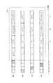
次に、上記図1及び図2、並びに、図3及び図4を用いて、本実施の形態におけるセキュア通信の通信方法について説明する。図3は、本実施の形態に係る送信装置において生成される送信信号のフレーム構成の一例を示す図である。図4は、本実施の形態に係る送信装置と受信装置との間の伝搬チャネルを示す図である。 Next, a secure communication method according to the present embodiment will be described with reference to FIGS. 1 and 2 and FIGS. 3 and 4. FIG. 3 is a diagram illustrating an example of a frame configuration of a transmission signal generated in the transmission apparatus according to the present embodiment. FIG. 4 is a diagram illustrating a propagation channel between the transmission apparatus and the reception apparatus according to the present embodiment.
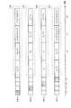
図3において、送信信号Aは、チャネル推定シンボル301、ガードシンボル302、データシンボル303の順でフレームが構成される。一方、送信信号Bは、ガードシンボル351、チャネル推定シンボル352、データシンボル353の順でフレームが構成される。送信信号Aと送信信号Bのフレームの先頭は同タイミングであり、ガードシンボル302、351は、送信信号Aのチャネル推定シンボル301と送信信号Bのチャネル推定シンボル352が時間的に重複しないように挿入される。この結果、チャネル推定シンボル301、352は時間的に独立なものとなる。 In FIG. 3, transmission signal A is composed of a frame in the order of
また、送信信号Aと送信信号Bを送信するアンテナは、アンテナ変更部105に記憶されたアンテナ変更パターンに従いフレーム単位で切替えられる。例えば、時刻t1からt2の間に送信されるフレームは、送信信号Aが送信アンテナ107−1から送信され、送信信号Bが送信アンテナ107−2から送信される。そして、受信アンテナ201−1には、チャネル変動h11(t)を受けた送信信号Aとチャネル変動h12(t)を受けた送信信号Bを合わせた信号が受信される。また、受信アンテナ201−2には、チャネル変動h21(t)を受けた送信信号Aとチャネル変動h22(t)を受けた送信信号Bを合わせた信号が受信される。 Further, the antennas that transmit the transmission signal A and the transmission signal B are switched in units of frames according to the antenna change pattern stored in the
また、時刻t2からt3の間に送信されるフレームは、送信信号Aが送信アンテナ107−2から送信され、送信信号Bが送信アンテナ107−3から送信される。そして、受信アンテナ201−1には、チャネル変動h12(t)を受けた送信信号Aとチャネル変動h13(t)を受けた送信信号Bを合わせた信号が受信される。また、受信アンテナ201−2には、チャネル変動h22(t)を受けた送信信号Aとチャネル変動h23(t)を受けた送信信号Bを合わせた信号が受信される。 In the frame transmitted between time t2 and t3, transmission signal A is transmitted from transmission antenna 107-2, and transmission signal B is transmitted from transmission antenna 107-3. The receiving antenna 201-1 receives a signal that is a combination of the transmission signal A that has received the channel fluctuation h12 (t) and the transmission signal B that has received the channel fluctuation h13 (t). The receiving antenna 201-2 receives a signal that is a combination of the transmission signal A that has received the channel fluctuation h22 (t) and the transmission signal B that has received the channel fluctuation h23 (t).
以下、同様に、フレーム単位で各信号を送信するアンテナが切り替わる。 Hereinafter, similarly, the antenna for transmitting each signal is switched in units of frames.
受信装置200は、チャネル推定部206−1〜206−4にてチャネル推定シンボルを用いてチャネル推定を行う。ここで、送信装置のアンテナ変更パターンは送信開始時において受信装置においても既知であり、チャネル推定部206−1〜206−4は、送信装置100におけるアンテナ変更信号と同一の送信パターン情報信号を用いることにより、送信信号が伝搬するチャネルが切り替わるタイミングに同期して改めてチャネル推定を
行う。In receiving
なお、チャネル推定部206−1〜206−4では、アンテナが切り替わった後のチャネルについて過去に推定したチャネル推定値を用いることによりチャネル推定を素早く行うことができる。 Note that the channel estimation units 206-1 to 206-4 can quickly perform channel estimation by using a channel estimation value estimated in the past for the channel after the antenna is switched.
また、チャネル推定部206−1〜206−4では、チャネル推定シンボルを入力しているとき、他方の送信信号はガードシンボルであることから、干渉が少ない状態でチャネル推定を高品質に行うことができる。 In addition, when channel estimation symbols are input in channel estimation sections 206-1 to 206-4, the other transmission signal is a guard symbol, so that channel estimation can be performed with high quality with little interference. it can.
これに対し、第三者は、送信装置100から送信された信号を傍受するためには、送信アンテナ切り替えにより伝搬するチャネルが変動するため、送信アンテナ切り替えの度に改めてチャネル推定を行う必要がある。しかしながら、送信アンテナ切り替えを示す情報が送信信号フレームに含まれないため、第三者は、アンテナ切り替えのタイミング及び送信信号が伝搬するチャネルを知る手段がない。したがって、第三者は、送信装置100から送信された信号を傍受することができない。 On the other hand, in order to intercept a signal transmitted from the
このように、本実施の形態では、複数の送信アンテナを有する送信装置が所定のパターンに基づき送信アンテナを切替えて信号を送信し、受信装置が送信装置の送信アンテナを切替えるタイミングに同期して送信装置と同一のパターンを用いてチャネル推定を行うことによりセキュア通信を実現することができる。 Thus, in the present embodiment, a transmission apparatus having a plurality of transmission antennas transmits a signal by switching the transmission antenna based on a predetermined pattern, and is transmitted in synchronization with the timing at which the reception apparatus switches the transmission antenna of the transmission apparatus. Secure communication can be realized by performing channel estimation using the same pattern as the apparatus.
なお、本実施の形態では、送信アンテナ数が3本、受信アンテナ数が2本の場合を例に説明したが、本発明はこの構成に限ったものではなく、送信アンテナ数が3本以上、受信アンテナ数が2本以上のアンテナで構成されていればよい。 In this embodiment, the case where the number of transmission antennas is 3 and the number of reception antennas is 2 has been described as an example. However, the present invention is not limited to this configuration, and the number of transmission antennas is 3 or more. It suffices if the number of receiving antennas is composed of two or more antennas.
また、本実施の形態では、マルチキャリア方式の例としてOFDM方式を用いたが、本発明はこれに限ったものではなく、スペクトル拡散通信方式(DS−CDMA(Direct Spread-Code Division Multiple Access)、FH(Frequency Hopping)−CDMA、UWB(Ultra Wide Band)等)を用いたOFDM方式、OFDM方式以外のマルチキャリア方式につ
いても同様に実施することができる。In the present embodiment, the OFDM scheme is used as an example of the multicarrier scheme.However, the present invention is not limited to this, and a spread spectrum communication scheme (DS-CDMA (Direct Spread-Code Division Multiple Access), The present invention can be similarly applied to OFDM schemes using FH (Frequency Hopping) -CDMA, UWB (Ultra Wide Band), etc., and multicarrier schemes other than OFDM schemes.
また、本実施の形態では、フレーム毎に送信アンテナの切り替えを行う場合について説明したが、本発明はこれに限られず、複数フレームに1度の割合で送信アンテナを切替えても、ランダムな間隔で送信アンテナを切替えてもセキュリティ効果を得ることができる。 In this embodiment, the case where the transmission antenna is switched for each frame has been described. However, the present invention is not limited to this, and even if the transmission antenna is switched at a rate of once every plural frames, the transmission antenna is switched at random intervals. Even if the transmission antenna is switched, a security effect can be obtained.
また、本発明では、チャネル推定シンボルを、過去のチャネル推定シンボルを補間するシンボル、すなわち、時間経過などにより変動するチャネル変動に追従するシンボルとすることもできる。例えば、図3において、時刻t1からt2においてアンテナ107−1、107−2からデータシンボルを送信することに加え、送信アンテナ107−3からもチャネル推定シンボルを送信する構成とすることで、時刻t2以降はチャネル変動に追従するシンボルとすることができる。これにより、1個のチャネル推定シンボルのみではチャネル推定が困難となるため、第三者が受信信号を復調することがより困難となり、セキュリティのさらなる向上を図ることができる。 Further, in the present invention, the channel estimation symbol may be a symbol that interpolates a past channel estimation symbol, that is, a symbol that follows a channel variation that varies with time. For example, in FIG. 3, in addition to transmitting data symbols from antennas 107-1 and 107-2 from time t1 to time t2, it is possible to transmit channel estimation symbols from transmission antenna 107-3, so that time t2 Thereafter, the symbol can follow the channel fluctuation. This makes channel estimation difficult with only one channel estimation symbol, making it more difficult for a third party to demodulate the received signal, and further improving security.
また、本実施の形態では、図3において、チャネル推定シンボル、ガードシンボルをデータシンボルの前に配置する場合について説明したが、本発明はこれに限られず、データシンボルの後ろにチャネル推定シンボル、ガードシンボルを配置しこれらのシンボルの前のデータシンボルを復調する構成や、データシンボル中にチャネル推定シンボル、ガードシンボルを配置し、これらのシンボルの前後のデータシンボルを復調する構成としても良い。 In the present embodiment, the case where the channel estimation symbol and the guard symbol are arranged before the data symbol in FIG. 3 has been described. However, the present invention is not limited to this, and the channel estimation symbol and the guard symbol are placed after the data symbol. A configuration in which symbols are arranged and data symbols preceding these symbols are demodulated, or a channel estimation symbol and a guard symbol are arranged in the data symbols, and data symbols before and after these symbols may be demodulated.
(実施の形態2)
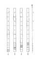
また、本発明では、上記図1の送信装置の構成、図2の受信装置の構成にて、図5に示すように、送信信号Aを送信するアンテナ(107−1)は固定とし、送信信号Bを送信するアンテナ(107−2、107−3)のみを切り替える構成とすることもできる。(Embodiment 2)
In the present invention, as shown in FIG. 5, the antenna (107-1) for transmitting the transmission signal A is fixed in the configuration of the transmission device in FIG. 1 and the configuration of the reception device in FIG. It is also possible to adopt a configuration in which only the antennas (107-2 and 107-3) that transmit B are switched.
この場合、図3のフレーム構成と比較して、送信信号Aを伝搬するチャネルが切り替わらないという点でセキュリティが低下するものの、送受信での処理が簡単になるという利点がある。 In this case, as compared with the frame configuration of FIG. 3, although the security is lowered in that the channel for transmitting the transmission signal A is not switched, there is an advantage that the processing in transmission / reception is simplified.
(実施の形態3)
また、本発明では、上記図1の送信装置の構成、図2の受信装置の構成にて、図6に示すように、アンテナ切り替え周期(アンテナ切り替えのパターンが一周して元に戻るまで
の時間)毎に、データシンボルの暗号化パターンを変更することもできる。図6では、時
刻t1からt4までの時間がアンテナ切り替え周期とした場合を示し、時刻t1からt4までに送信されるデータシンボルには暗号化パターン1が用いられ、時刻t4以降に送信されるデータシンボルには暗号化パターン2が用いられる。ここで、データシンボルの暗号化パターンとしては、データをインタリーブやスクランブルするパターンを変更するもの、誤り訂正符号(リードソロモン符号、畳み込み符号・ターボ符号・LDPC(Low Density Parity Check)符号など)を変更するもの、公開鍵暗号方式(RSA方式など)や秘密鍵暗号方式(DES方式など)の暗号方式を変更するもの、等が挙げられる。例えば、時刻t1からt2にかけて信号が傍受されており、かつ時刻t1からt4でチャネルの変動が小さいために時刻t1以降に改めてチャネル推定する必要がなく、時刻t4においても容易に傍受可能である場合においても、時刻t4以降には異なる暗号化パターンで送信することにより傍受することは困難とすることができ、セキュリティを確保することができる。(Embodiment 3)
Further, in the present invention, as shown in FIG. 6, in the configuration of the transmitting device in FIG. 1 and the configuration of the receiving device in FIG. 2, the antenna switching period (the time until the antenna switching pattern makes a round and returns to the original state). ), The data symbol encryption pattern can be changed every time. FIG. 6 shows the case where the time from time t1 to t4 is the antenna switching period, and the
(実施の形態4)
また、本発明では、上記図1の送信装置の構成、図2の受信装置の構成にて、図7に示すように、送信パケット数に基づいてアンテナ切り替えを行うこともできる。さらに、送信データビット数、送信におけるパケット割り当てに関して優先権をもったパケットが伝送された数(例えば、再送することなく必ず一回で送信したいパケットが伝送された数)など、時間ではなく量を表すパラメータであれば、図7に示す構成は可能である。これらの送信データビット数、送信パケット数、優先権を持ったパケット数についても、ランダムな間隔で送信アンテナを切替えても良い。(Embodiment 4)
Also, in the present invention, antenna switching can be performed based on the number of transmission packets as shown in FIG. 7 in the configuration of the transmission device in FIG. 1 and the configuration of the reception device in FIG. In addition, the amount of data rather than time, such as the number of transmitted data bits and the number of packets that have priority with respect to packet allocation in transmission (for example, the number of packets that must be transmitted at one time without being retransmitted). The configuration shown in FIG. 7 is possible as long as it represents parameters. The transmission antennas may be switched at random intervals with respect to the number of transmission data bits, the number of transmission packets, and the number of packets having priority.
(実施の形態5)
実施の形態5では、時空間ブロック符号を用いてセキュア通信を行う方法を説明する。(Embodiment 5)
In the fifth embodiment, a method for performing secure communication using a space-time block code will be described.
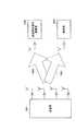
図8は、本実施の形態に係るマルチアンテナ通信システム800の全体構成を示す図である。マルチアンテナ通信システム800において、送信装置801は、4本のアンテナ802−1〜802−4を有し、各アンテナ802−1〜802−4から同時に信号を送信する。受信装置851は、各アンテナ802−1〜802−4から同時に送信された信号をアンテナ852で受信する。なお、アンテナ802−1から送信された信号はチャネル変動h1(t)を受けてアンテナ852で受信され、以下同様に、アンテナ802−2、802−3、802−4から送信された信号はチャネル変動h2(t)、h3(t)、h4(t)を受けてアンテナ852で受信される。なお、以降の説明では、時空間ブロック符号化されたシンボルを受信する時間内において伝搬路(チャネル)の時間変動はないものと仮定する。 FIG. 8 is a diagram showing an overall configuration of multi-antenna communication system 800 according to the present embodiment. In the multi-antenna communication system 800, the
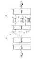
図9は、本実施の形態に係る送信装置801の構成を示すブロック図である。図9において、送信装置801は、データ分流部901と、変調部902−1〜902−3と、パイロット信号生成部903と、フレーム構成信号生成部904と、信号形成部905と、拡散部906−1〜906−4と、無線部907−1〜907−4と、アンテナ802−1〜802−4とから主に構成される。 FIG. 9 is a block diagram showing a configuration of transmitting
データ分流部901は、送信データを分流し、変調部902−1、902−2、902−3に出力する。 The
変調部902−1は、送信データに対してディジタル変調処理を施し、得られた送信シンボルS1を信号形成部905に出力する。例えばQPSKの場合には、2ビットの送信データから1つの送信シンボルS1を得る。同様に、変調部902−2、902−3は、それぞれ送信データに対してディジタル変調処理を施し、得られた送信シンボルS2、S3を信号形成部905に出力する。 Modulation section 902-1 performs digital modulation processing on the transmission data and outputs the obtained transmission symbol S1 to signal forming
パイロット信号生成部903は、パイロット信号を生成し、信号形成部905に出力する。 Pilot
フレーム構成信号生成部904は、信号配置パターンを内部メモリに記憶し、クロック信号を入力する毎に信号配置パターンに従って信号配置の変更を指示する信号配置変更信号を生成し、これを信号形成部905に出力する。 The frame configuration
信号形成部905は、送信シンボルS1、S2、S3を用いて時空間ブロック符号化信号を形成し、パイロット信号を定期的に挿入し、時空間ブロック符号化信号とパイロット信号を拡散部906−1〜906−4に出力する。信号形成部905は、信号配置変更信号を入力する毎に、時空間ブロック符号化信号の信号配置パターンを変更する。なお、時空間ブロック符号化信号の具体例は後述する。 The
拡散部906−1〜906−4は、それぞれ時空間ブロック符号信号に拡散符号を乗算し、拡散後の信号を無線部907−1〜907−4に出力する。 Spreading units 906-1 to 906-4 each multiply the space-time block code signal by a spreading code, and output the spread signals to radio units 907-1 to 907-4.
無線部907−1〜907−4は、それぞれ拡散部906−1〜906−4の出力信号に対して周波数変換等の所定の無線処理を施し、これにより得た無線送信信号をアンテナ802−1〜802−4に供給する。 The radio units 907-1 to 907-4 perform predetermined radio processing such as frequency conversion on the output signals of the spreading units 906-1 to 906-4, respectively, and transmit the radio transmission signals thus obtained to the antenna 802-1. To 802-4.
図10は、本実施の形態に係る受信装置851の構成を示すブロック図である。図10において、受信装置851は、アンテナ852と、無線部1001と、逆拡散部1002と、チャネル推定部1003−1〜1003−4と、同期部1004と、フレーム構成信号記憶部1005と、復調部1006とから主に構成され、図8の送信装置801から送信された時空間ブロック符号化信号を受信する。 FIG. 10 is a block diagram showing a configuration of receiving
無線部1001は、アンテナ852に受信された信号に対して周波数変換などの所定の無線受信処理を施し、これにより得られた受信ベースバンド信号を逆拡散部1002に出力する。逆拡散部1002は、受信ベースバンド信号を逆拡散し、逆拡散後の受信ベースバンド信号を、チャネル推定部1003−1〜1003−4、同期部1004、フレーム構成信号記憶部1005及び復調部1006に出力する。
チャネル推定部1003−1は、アンテナ801−1から送信された信号に含まれるパイロットシンボルに基づいて、アンテナ801−1とアンテナ852との間のチャネル変動h1を求め、これを復調部1006に出力する。同様に、チャネル推定部1003−2、1003−3、1003−4は、それぞれチャネル変動h2、h3、h4を求め、これを復調部1006に出力する。 Channel estimation section 1003-1 obtains channel fluctuation h1 between antenna 801-1 and
同期部1004は、受信信号に含まれるパイロットシンボルに基づき、アンテナ801−1、801−2、801−3、801−4から送信された信号の同期を取り、復調部における復調のタイミング同期のためのタイミング信号を復調部1006に出力する。 Synchronizing
フレーム構成信号記憶部1005は、図9に示したフレーム構成信号生成部904に記憶された信号配置パターンと同一のものを内部メモリに記憶し、受信ベースバンド信号を入力する毎に信号配置パターンに従って信号配置の変更を指示する信号配置変更信号を生成し、これを復調部1006に出力する。 The frame configuration
復調部1006は、チャネル変動h1、h2、h3、h4、受信ベースバンド信号(送信側での時点i、i+1、i+2、i+3に対応する受信ベースバンド信号をR(t)、R(t+1)、R(t+2)、R(t+3)と定義する)、タイミング信号、信号配置変更信号を入力とし、信号配置変更信号に基づいて例えば時空間ブロック符号化された送信信号行列に対応する逆行列演算を行い、復調送信シンボルS1’、S2’、S3’を求め、前記S1’、S2’、S3’を復調して受信ディジタルデータを出力する。 The
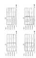
図11は、本実施の形態に係る送信フレーム構成の一例を示した図である。図中の網掛け部分はパイロットシンボルを、塗りつぶし無しの部分はヌルシンボル(無信号)を示す。パイロットシンボルは、時点i−4で802−1から、時点i−3で802−2から、時点i−2で802−3から、時点i−1で802−4から送信される。 FIG. 11 is a diagram showing an example of a transmission frame configuration according to the present embodiment. In the figure, shaded portions indicate pilot symbols, and unfilled portions indicate null symbols (no signal). The pilot symbols are transmitted from 802-1 at time point i-4, from 802-2 at time point i-3, from 802-3 at time point i-2, and from 802-4 at time point i-1.
続く時点iからi+3で、送信信号列ベクトル1101〜1104、送信信号行ベクトル1105〜1108からなる送信信号行列1110が送信される。なお、図11に示す時空間ブロック符号化方法は、「”Space-Time Block Coding for Wireless Communications: Performance Results” IEEE JOURNAL ON SELECTED AREAS IN COMMUNICATIONS ,pp451-460,vol.17,no.3,March 1999」で示されている方法である。また、*は複素共役を示す記号である。一般に、時空間ブロック符号化を施すと、送信信号列ベクトル同士(例えば時点iの送信信号列ベクトル1101と、時点i+1の送信信号列ベクトル1102)が直交関係となり、受信側での信号分離時においてチャネル変動にかかわらず送信信号を最大比合成できるので、大きなダイバーシチゲインが得られる。この結果、受信品質が向上する。なお、受信側で最大比合成する方法として、上記の他に相関行列を用いる方法等が知られている。本発明では、最大比合成する方法に制限はない。 At subsequent time points i to i + 3, a
このとき、送信シンボルS1、S2、S3の復調送信シンボルS1’、S2’、S3’は、以下の式(1)から(3)で表される。In this case, the demodulated transmission symbolsS 1 transmission symbolS 1, S 2, S 3 ', S 2', S 3 ' is expressed by the following equation (1) (3).

図12は、図11に示した送信フレーム構成に対して、送信信号列ベクトルの送信順を入れ替え、送信信号列ベクトル1104を時点iで送信し、送信信号列ベクトル1101を時点i+1で送信し、送信信号列ベクトル1102を時点i+2で送信し、送信信号列ベクトル1103を時点i+3で送信する場合の、送信フレーム構成を示す図である。 12 replaces the transmission order of transmission signal sequence vectors with respect to the transmission frame configuration shown in FIG. 11, transmits transmission
図13は、図11に示した送信フレーム構成に対して、アンテナ802−1〜802−4に割り当てる送信信号行ベクトルを入れ替え、送信信号行ベクトル1108をアンテナ802−1で送信し、送信信号行ベクトル1105をアンテナ802−2で送信し、送信信号行ベクトル1106をアンテナ802−3で送信し、送信信号行ベクトル1107をアンテナ801−4で送信する場合の、送信フレーム構成を示す図である。 13 replaces the transmission signal row vectors assigned to the antennas 802-1 to 802-4 with respect to the transmission frame configuration shown in FIG. 11, and transmits the transmission
ここで、送信装置801において、送信フレーム構成を図11から図12あるいは図13に変更しても、送信装置801のフレーム構成信号生成部904と受信装置851のフレーム構成信号記憶部1005とが同一の信号配置パターンを用いることにより、図12あるいは図13に変更された後でも受信装置851において図11と同様に、送信信号を最大比合成して大きなダイバーシチゲインを得ることができ、受信品質を向上させることができる。 Here, in the
ここで、受信側で送信フレーム構成を誤って復調した場合(例えば図12の送信フレーム構成で送信した信号を図11の送信フレーム構成と誤って復調した場合)、送信信号行列の直交性が崩れ、受信品質が大きく劣化する。これをセキュア通信の観点で見ると、所望の受信者(正しい送信フレーム構成を知っている受信者)と傍受者(正しい送信フレーム構成を知らない受信者)の間の受信品質の差が大きくなり、セキュア性の高い通信が可能となるということになる。 Here, when the receiving frame is erroneously demodulated on the receiving side (for example, when a signal transmitted with the transmission frame configuration of FIG. 12 is erroneously demodulated with the transmission frame configuration of FIG. 11), the orthogonality of the transmission signal matrix is lost. The reception quality is greatly degraded. From the viewpoint of secure communication, the reception quality difference between the desired receiver (recipient who knows the correct transmission frame configuration) and the interceptor (recipient who does not know the correct transmission frame configuration) increases. This means that highly secure communication is possible.
また、時空間ブロック符号を形成する送信信号行列(図11の1110など)を構成する送信シンボル(図11では16個)は、その送信信号行列内における配置場所に制限はなく、二次元行列内(時間方向とアンテナ方向)に任意に割り当てることができる。このとき、割り当てパターン数はn個のうちk個を並べる場合のパターン数を示す記号Pを用いて、nPk通り(図15の場合、16P16(16x15x・・・x2x1)通り)存在する。これは、スペクトル拡散通信で拡散符号として用いるM系列などの一次元行列と異なり、非常に多数のパターンを使うことができるため、セキュア性の高い通信が可能となるということになる。また、本実施の形態で示したように、時空間ブロック符号を用いる場合、伝送レートを落とさずにセキュア通信が可能となる点も利点である。In addition, the transmission symbols (16 in FIG. 11) constituting the transmission signal matrix (such as 1110 in FIG. 11) forming the space-time block code are not limited in the arrangement location in the transmission signal matrix, and are within the two-dimensional matrix. (Time direction and antenna direction) can be arbitrarily assigned. At this time, the number of allocation patterns with symbol P that indicates the number of patterns in the case of arranging the k pieces of n,n Pk as (in the case of FIG.15, 16 P 16 (16x15x ··· x2x1) street) existing To do. This means that, unlike a one-dimensional matrix such as an M sequence used as a spread code in spread spectrum communication, a very large number of patterns can be used, so that highly secure communication is possible. Further, as shown in the present embodiment, when a space-time block code is used, there is an advantage that secure communication can be performed without reducing the transmission rate.
なお、時空間ブロック符号化方法は、以上説明した方法に限ったものではなく、例えば「”A Quasi-Orthogonal Space-Time Block Code” IEEE TRANSACTIONS ON COMMUNICATIONS ,pp1-4, vol.49, no.1, JANUARY 2001」で示されている方法がある。この方法は準直交時空間ブロック符号化方法と呼ばれる方法であり、これを用いる際の送信フレーム構成の一例を図14に示す。この方法では、送信信号行列の送信信号列ベクトルが部分的に直交する構成となっており(行ベクトルも同様)、受信側でシンボル毎に分離することができないため、先に引用した「”Space-Time Block Coding for Wireless Communications: Performance Results” IEEE JOURNAL ON SELECTED AREAS IN COMMUNICATIONS ,pp451-460,vol.17,no.3,March 1999」で示されている直交時空間ブロック符号(図11など)と比較して受信側の処理が複雑となり、またダイバーシチゲインが小さくなる。しかし、準直交時空間ブロック符号では、直交時空間ブロック符号と比較して伝送レートを大きく取れるという利点がある。以上説明した準直交時空間ブロック符号のように、直交時空間ブロック符号と異なる時空間ブロック符号を用いることで符号の選択パターンが増え、さらにセキュア性の高い通信が可能となる。 The space-time block coding method is not limited to the method described above. For example, ““ A Quasi-Orthogonal Space-Time Block Code ”IEEE TRANSACTIONS ON COMMUNICATIONS, pp1-4, vol.49, no.1 , JANUARY 2001 ". This method is a method called a quasi-orthogonal space-time block coding method, and an example of a transmission frame configuration when using this method is shown in FIG. In this method, the transmission signal matrix vectors of the transmission signal matrix are partially orthogonal (the row vectors are also the same) and cannot be separated for each symbol on the receiving side. -Time Block Coding for Wireless Communications: Performance Results ”IEEE JOURNAL ON SELECTED AREAS IN COMMUNICATIONS, pp451-460, vol.17, no.3, March 1999” In comparison, the processing on the receiving side is complicated, and the diversity gain is reduced. However, the quasi-orthogonal space-time block code has an advantage that a transmission rate can be increased as compared with the orthogonal space-time block code. By using a space-time block code that is different from the orthogonal space-time block code as in the quasi-orthogonal space-time block code described above, the code selection pattern increases, and communication with higher security is possible.
以上の説明では、送信信号行列を用いたセキュア通信方法を説明したが、以下ではパイロットシンボルを用いたセキュア通信方法を説明する。 In the above description, the secure communication method using the transmission signal matrix has been described. Hereinafter, the secure communication method using pilot symbols will be described.
図15は、図11の送信フレーム構成に対して、パイロットシンボル構成を変更した構成を示す図である。この構成を用いる場合においても、送信装置801と受信装置851との間でこのパイロットシンボル構成をあらかじめ共有していれば、チャネル変動h1、h2、h3、h4の推定を行って送信シンボルS1、S2、S3を復調することができる。しかし、図15に示すパイロットシンボル構成を送信装置801と共有できていない受信装置では、パイロットシンボルの推定は可能であるもののその推定値がh1、h2、h3、h4のどのチャネル変動に相当するものかわからない。よって、送信シンボルを正確に復調することは困難になる。このパイロットシンボルの時間方向、アンテナ方向への割り当ても、2次元行列の中で割り当てを考えることができ、多数のパターンを使うことができるため、セキュア性の高い通信が可能となる。また、パイロットシンボルとして時空間ブロック符号化されたシンボルを使う場合、チャネル変動の推定を高精度に行うことができ、かつセキュア性の高い通信が可能となる。 FIG. 15 is a diagram showing a configuration in which the pilot symbol configuration is changed with respect to the transmission frame configuration of FIG. Even when this configuration is used, if the pilot symbol configuration is shared between the
以下では、本実施の形態のセキュア通信方法を用いたシステムの実施例について図16を用いて説明する。図16には、本実施の形態で示したセキュア通信方法で通信することができる送信者1601、送信者1601が通信を行いたい相手である所望の受信者1602、送信者1601と所望の受信者1602の通信を傍受しようとしている傍受者1603が示されている。 Hereinafter, an example of a system using the secure communication method of the present embodiment will be described with reference to FIG. FIG. 16 shows a
送信者1601と所望の受信者1602との間のチャネル変動1604は、この二者間で共有できているものとする(例えば上り下りで同一の周波数を使うTDD(Time Division Duplex)システムであればチャネル変動は上り下りで同一とみなせるため、共有可能である)。 The
このとき送信者1601は、チャネル変動1604から、所望の受信者1602にとって最低限必要なCNR(Carrier-to-Noise Ratio)となるように送信電力を制御して送信する。これにより、所望の受信者1602は、必要なデータを得ることが可能である。しかし、傍受者1603は、たとえ送信者1601と傍受者1603との間のチャネル変動1605がチャネル変動1604と同じとみなせる値であったとしても、送信フレーム構成を知らなければ時空間ブロック符号を正確に復調できず、大きく劣化した受信品質となり、所望の受信者1602が必要とするデータを解読することは非常に困難となる。 At this time, the
以上説明したように、本実施の形態のシステムを用いることにより、所望の相手と高いセキュア性を有する通信が可能となる。このとき、所望の受信者1602が、受信品質を示す値として例えばRSSI(Received Signal Strength Indicator)の値を、送信者1601に送信する構成としても、同様に実施することができる。 As described above, by using the system of this embodiment, communication with high security can be made with a desired partner. At this time, a configuration in which the desired
なお、上記各実施の形態はUWB(Ultra Wide Band)通信でも有効である。本実施の形態においてUWB通信を行う場合は、図9の送信装置801と図10の受信装置851から無線部を取り除いた構成となる。UWB通信では、信号を1GHz程度の極めて広い周波数帯に拡散して送受信を行い、それぞれの周波数帯に送信される信号は雑音程度の電力である。したがって、傍受者は送信機とパターンを共有していない限り、非常に小さな電力しか利用することができず、傍受は非常に困難となる。また、各アンテナからの受信信号電力の大小関係が小さいことも、本実施の形態のセキュア通信を行いやすくする点である。 Each of the above embodiments is also effective for UWB (Ultra Wide Band) communication. In the case of performing UWB communication in this embodiment, the wireless unit is removed from the
なお、上記実施の形態では、アンテナ変更パターン、時空間ブロック符号化の送信行ベクトル変更パターンなどをあらかじめ共有するとして説明を行ったが、パターン変更を、例えばRSSIの値に基づいて変更することで、傍受者が全てのパターンを総当たりで復調を行った場合においても、傍受される確率を下げることができる。このパターン変更を行うことで、本実施の形態のセキュア通信はより高いセキュア性を持った通信となる。このとき、送信装置801ではフレーム構成信号生成部904に信号配置パターン情報が入力されて信号配置パターンが変更される。また、受信装置851ではフレーム構成信号記憶部1005に受信ベースバンド信号が入力されて信号配置パターンが変更され、フレーム構成信号とタイミング情報を用いて、復調送信シンボルが取得される。 In the above embodiment, the antenna change pattern, the space-time block coding transmission row vector change pattern, and the like have been described as being shared in advance. However, by changing the pattern change based on the RSSI value, for example, Even when the eavesdropper demodulates all patterns, the probability of eavesdropping can be reduced. By performing this pattern change, the secure communication of the present embodiment becomes communication with higher security. At this time, in the
また、前記アンテナ変更パターン、前記時空間ブロック符号化の送信行ベクトル変更パターン、暗号化が施されている通信における暗号鍵など、絶対に所望の相手以外に知られたくないあるいは知られてはいけない情報を、本実施の形態で示したセキュア通信方法を用いて送信し、その他のデータは本実施の形態のセキュア通信を行わずに送信することで、データの伝送効率低下を小さく抑えつつ、セキュア性の高い通信が可能となる。 Also, the antenna change pattern, the transmission space vector change pattern of the space-time block encoding, the encryption key in the communication that is encrypted, etc. should never be known or known to anyone other than the desired counterpart. Information is transmitted using the secure communication method shown in the present embodiment, and other data is transmitted without performing secure communication of the present embodiment, so that a decrease in data transmission efficiency can be kept small and secure. High-performance communication is possible.
なお、本実施の形態で示した方法は、時空間ブロック符号化された送信シンボルを、送信信号行ベクトルまたは列ベクトルの入れ替えにより時間方向とアンテナ方向に割り当てたが、この割り当て方法に限ったものではなく、時空間ブロック符号化された送信シンボルをランダムインタリーブするように拡散して割り当てても同様に実施することができる。また、周波数方向に割り当てることも可能である。図17は、時空間ブロック符号化された送信シンボルを周波数方向に割り当てる一例を示す図であり、OFDM(Orthogonal Frequency Division Multiplexing)変調して送信する場合を示す。なお、OFDM変調を用いる場合の送受信機の基本的な構成については、図1と図2で示したのでここでは詳細は省略するが、図9において拡散部を取り除き、S/P部とIFFT部を挿入し、図10において逆拡散部を取り除き、P/S部とFFT部を挿入することで、OFDM変調を用いるシステムが構成される。 In the method shown in this embodiment, the space-time block-coded transmission symbols are allocated in the time direction and the antenna direction by exchanging transmission signal row vectors or column vectors. However, this method is limited to this allocation method. Instead, the same can be implemented by spreading and assigning transmission symbols that are space-time block coded so as to be randomly interleaved. It is also possible to assign in the frequency direction. FIG. 17 is a diagram illustrating an example of assigning space-time block-coded transmission symbols in the frequency direction, and illustrates a case where OFDM (Orthogonal Frequency Division Multiplexing) modulation is performed for transmission. The basic configuration of the transmitter / receiver in the case of using OFDM modulation is shown in FIGS. 1 and 2 and will not be described in detail here. However, in FIG. 9, the spreading unit is removed, and the S / P unit and IFFT unit are removed. 10 is removed, the despreading unit is removed in FIG. 10, and the P / S unit and the FFT unit are inserted to form a system using OFDM modulation.
図17は、図8に示す送信装置801からOFDM変調信号(サブキャリア数4)を送信する場合の送信フレーム構成の一例を示したものである。図11においてアンテナ802−1〜802−4に配置されていた送信信号列ベクトル1101を、アンテナ802−1で送信するOFDM変調信号のサブキャリア1から4に配置し、以下同様に、図11の送信信号列ベクトル1102、1103、1104をそれぞれ、アンテナ802−2、802−3、802−4で送信するOFDM変調信号のサブキャリアに配置している。この配置のように、OFDM変調信号を用いる場合には、OFDM変調信号内で時間方向と周波数方向に配置可能であり(図17では周波数方向にのみ配置したが時間方向にも配置できることは明らかである)、この2つにアンテナ方向の割り当てを加え、3次元行列で送信フレーム構成が可能であり、1次元行列、2次元行列での構成と比較してより多くのパターンを用いることができる。よって、より高いセキュア性を持った通信が可能となる。 FIG. 17 shows an example of a transmission frame configuration when an OFDM modulated signal (number of subcarriers 4) is transmitted from
なお、以上の説明において、サブキャリア数は4としたがこれは一例であり、一般に多くのサブキャリアを用いるほど、高セキュア通信が可能となる。また、アンテナ数に関しても同様であり、送信アンテナ:4、受信アンテナ:1に限ったものではなく、例えば送信アンテナ:2、受信アンテナ:2の場合でも、同様に実施できる。このとき、2つの受信アンテナそれぞれで復調した送信シンボルを最大比合成することで、受信品質を向上させることができるため、所望の受信者と傍受者の受信品質の差が大きくなり、より高いセキュア性を持った通信が実施できる。 In the above description, the number of subcarriers is four, but this is only an example. In general, as more subcarriers are used, higher secure communication is possible. The same applies to the number of antennas, and is not limited to 4 for transmission antennas and 1 for reception antennas. For example, the same applies to the case of 2 transmission antennas and 2 reception antennas. At this time, since the reception ratio can be improved by combining the transmission symbols demodulated by each of the two reception antennas with the maximum ratio, the difference in reception quality between the desired receiver and the eavesdropper is increased, and higher security is achieved. Communication can be carried out.
また、本実施の形態において、拡散を行わない場合は、図9の拡散部、図10の逆拡散部を取り除いた構成となる。 Further, in the present embodiment, when diffusion is not performed, the configuration is such that the diffusion unit in FIG. 9 and the despreading unit in FIG. 10 are removed.
(その他の実施の形態)
ここで、本発明のシステムを活用する例として、家庭内におけるホームネットワークシステムで説明を行う。(Other embodiments)
Here, a home network system in a home will be described as an example of utilizing the system of the present invention.
近年、ハードディスク(HD:Hard Disk)、DVD−ROM等を記憶媒体とするディジ
タル再生・録画装置の普及が進んでいる。ディジタル再生・録画装置は、情報の劣化を伴わない、頭出し再生が高速にできる、生放送中の番組を一旦停止しておいて数分後から続きを見ることができる、など従来のVTRでは実現が困難・不可能であった機能を実現できる。また、インターネットと接続して最新のEPG(Electronic Program Guide:電子
番組ガイド)をディジタル再生・録画装置にダウンロードし、外出先からでもディジタル
再生・録画装置の操作が可能である機能を持つ等、ネットワークを通じた操作も可能である。In recent years, digital reproduction / recording apparatuses using a hard disk (HD: Hard Disk), DVD-ROM, or the like as a storage medium have been widely used. The digital playback / recording device is realized with conventional VTRs, such as high-speed playback with no cueing information, and the ability to pause a program during live broadcasting and watch the continuation several minutes later. Can realize functions that were difficult or impossible. In addition, the latest EPG (Electronic Program Guide) connected to the Internet is downloaded to a digital playback / recording device, and the digital playback / recording device can be operated from a remote location. The operation through is also possible.
また、家庭内においては無線LANシステムがADSL、FTTHなどのブロードバンド回線の普及とともに進んでいる。さらに、無線LANシステムと同様に、テレビやビデオの映像を、ワイヤレスシステムを用いて家庭内に送信するホームネットワークシステムも普及し始めている。この一例を図18に示す。受信アンテナ1801で受信された受信信号は、ホームサーバ1802に蓄積される。また、ADSL、FTTH等のブロードバンド回線を通してTCP/IP伝送などによりネットワーク1803から配信された受信信号も、ホームサーバ1802に蓄積される。ここで、ホームサーバ1802は、ハードディスク等を記憶媒体とするディジタル再生・録画装置を含む。 Further, in homes, wireless LAN systems are progressing with the spread of broadband lines such as ADSL and FTTH. Furthermore, as with the wireless LAN system, home network systems that transmit television and video images to the home using a wireless system are also becoming popular. An example of this is shown in FIG. A reception signal received by the
ホームサーバ1802は、受信アンテナ1801あるいはネットワーク1803から受信した受信信号や、記憶媒体の映像、音声、データなどを信号処理して、家庭内のPC(Personal Computer)1804、TV(Television)1805に向けて無線送信する。PC1804やTV1805はそれぞれ受信アンテナを所有し、ホームサーバ1802から送信された信号を受信し、映像、音声、データを取得、表示する。このようなワイヤレスシステムは、家庭内のさまざまな場所でPCやTVを使用することができ、煩わしい配線も不要である、などの利点があり、今後のさらなる普及が見込まれる。 The
本発明のような複数の送受信アンテナを用いて複数の信号を送受信するシステムは、送受信に1本ずつのアンテナを用いるシステムと比較して、同一周波数帯域においてチャネル容量を増加させることが理論的に可能なシステムであり、多くの研究がなされている。チャネル容量の増加は、高速大容量の伝送を行う上記ワイヤレスシステムにおいて、非常に有用である。 A system that transmits and receives a plurality of signals using a plurality of transmitting and receiving antennas as in the present invention theoretically has an increased channel capacity in the same frequency band as compared with a system that uses one antenna for transmitting and receiving. It is a possible system and a lot of research has been done. The increase in channel capacity is very useful in the wireless system that performs high-speed and large-capacity transmission.
上記ワイヤレスシステムにおいては、電波は一般にその受信を希望する人・物のみならず、周辺の人・物にも伝搬する。例えば、図18の場合、ホームサーバ1802からある世帯のPC1804やTV1805に向けて送信された送信信号が、隣接する世帯のPC1806やTV1807にも届く。この場合、PC1806やTV1807にとってホームサーバからの送信信号が干渉となる場合もあり、また、ホームサーバからの送信信号が意図的に傍受される場合もあり得る。特に、信号を意図的に傍受されることは、信号が放送であれば何の番組を見ているかというプライバシーの問題、番組が有料放送であった場合に契約していない人が無料で受信できるという問題、ディジタルのコンテンツが再利用される問題など、様々な問題が考えられる。 In the wireless system described above, the radio wave generally propagates not only to the person / thing that wants to receive it but also to the surrounding person / thing. For example, in the case of FIG. 18, a transmission signal transmitted from the
意図的な傍受に関して、現在の無線LANシステムにおけるセキュリティの脆弱性は、有名かつ深刻な問題の1つである。無線LANシステムにおいては、無線LANモデムなどのアクセスポイントへのアクセスの際に、IDやパスワードによるアクセス制限を行うが、IDが簡単に推測されるケースやパスワードが数日程度で解読されるケースが数多く報告されており、これは複数の送受信アンテナを用いるシステムにおいてもIDやパスワードなどのアクセス制限を用いた場合、同様に起こりうる問題である。よって、これまでとは異なる種類のセキュリティの施し方が望まれる。 With regard to intentional interception, security vulnerabilities in current wireless LAN systems are one of the famous and serious problems. In a wireless LAN system, access to an access point such as a wireless LAN modem is restricted by an ID or a password. However, there are cases where an ID can be easily guessed or a password can be decoded within a few days. Many reports have been made. This is a problem that can occur in a system using a plurality of transmission / reception antennas when access restrictions such as IDs and passwords are used. Therefore, a different kind of security is required.
複数のアンテナを使用する場合、そのアンテナが常に同じであると、信号が伝搬するチャネルを切り替えることはできないため、一旦第三者により傍受された場合に傍受され続ける可能性があるが、これに対し送信アンテナを切り替えると信号が伝搬するチャネルも切り替え前とは異なるチャネルとなり、この切り替えを継続して行うことで、送信信号の傍受に対するセキュリティを向上させることができる。 When using multiple antennas, if the antennas are always the same, the channel on which the signal propagates cannot be switched, so if it is intercepted by a third party, it may continue to be intercepted. On the other hand, when the transmission antenna is switched, the channel through which the signal propagates is also different from the channel before the switching, and security for transmission signal interception can be improved by continuing this switching.
本発明は、セキュア通信を行う無線通信システムの基地局装置及び通信端末装置に用いるに好適である。 The present invention is suitable for use in a base station apparatus and a communication terminal apparatus of a wireless communication system that performs secure communication.
100 送信装置
101 フレーム構成部
102 S/P部
103 IDFT部
104 無線部
105 アンテナ変更部
106 アンテナ選択部
107 送信アンテナ
200 受信装置
201 受信アンテナ
202 無線部
203 DFT部
204 パターン記憶部
205 データ分離部
206 チャネル推定部
207 信号処理部
801 送信装置
802 アンテナ
851 受信装置
852 アンテナ
901 データ分流部
902 変調部
903 パイロット信号生成部
904 フレーム構成信号生成部
905 信号形成部
906 拡散部
907 無線部
1001 無線部
1002 逆拡散部
1003 チャネル推定部
1004 同期部
1005 フレーム構成信号記憶部
1006 復調部
DESCRIPTION OF
Claims (9)
Translated fromJapanese前記送信装置と同一のアンテナ変更パターンを記憶する受信装置において、受信した前記送信装置からの信号をダウンコンバートして受信ディジタル信号を生成する工程と、前記送信装置が送信アンテナを切替えるタイミングに同期して前記受信ディジタル信号からデータシンボルとチャネル推定用のシンボルを分離する工程と、前記アンテナ変更パターンに基づき前記分離されたチャネル推定用のシンボルを用いてチャネル推定を行う工程と、チャネル推定値に基づいて前記データシンボルを復調する工程と、を具備するセキュア通信方法。In a transmission apparatus having a plurality of transmission antennas, a step of inserting a symbol for channel estimation into digital data to generate a transmission digital signal, a step of up-converting the transmission digital signal to generate a transmission signal, Selecting an antenna according to an antenna change pattern; and wirelessly transmitting the plurality of transmission signals using the selected antenna;
In the receiving apparatus that stores the same antenna change pattern as the transmitting apparatus, the received signal from the transmitting apparatus is down-converted to generate a received digital signal, and the timing at which the transmitting apparatus switches the transmitting antenna is synchronized. Separating a data symbol and a channel estimation symbol from the received digital signal, performing channel estimation using the separated channel estimation symbol based on the antenna change pattern, and based on a channel estimation value And a step of demodulating the data symbol.
Priority Applications (6)
| Application Number | Priority Date | Filing Date | Title |
|---|---|---|---|
| JP2004258919AJP2005110228A (en) | 2003-09-10 | 2004-09-06 | Secure communication method, transmitter, and receiver |
| US10/570,790US7646822B2 (en) | 2003-09-10 | 2004-09-09 | Antenna selective diversity |
| CN2004800253387ACN1846367B (en) | 2003-09-10 | 2004-09-09 | Secure communication method, transmission apparatus and reception apparatus |
| EP04787834AEP1667340A4 (en) | 2003-09-10 | 2004-09-09 | PROTECTED COMMUNICATION METHOD, TRANSMITTING APPARATUS, AND RECEPTION APPARATUS |
| PCT/JP2004/013171WO2005027372A1 (en) | 2003-09-10 | 2004-09-09 | Secure communication method, transmission apparatus and reception apparatus |
| US12/637,524US8457234B2 (en) | 2003-09-10 | 2009-12-14 | Radio communication method and apparatus selectively employing a plurality of antennas |
Applications Claiming Priority (2)
| Application Number | Priority Date | Filing Date | Title |
|---|---|---|---|
| JP2003318809 | 2003-09-10 | ||
| JP2004258919AJP2005110228A (en) | 2003-09-10 | 2004-09-06 | Secure communication method, transmitter, and receiver |
Publications (1)
| Publication Number | Publication Date |
|---|---|
| JP2005110228Atrue JP2005110228A (en) | 2005-04-21 |
Family
ID=34315650
Family Applications (1)
| Application Number | Title | Priority Date | Filing Date |
|---|---|---|---|
| JP2004258919APendingJP2005110228A (en) | 2003-09-10 | 2004-09-06 | Secure communication method, transmitter, and receiver |
Country Status (5)
| Country | Link |
|---|---|
| US (2) | US7646822B2 (en) |
| EP (1) | EP1667340A4 (en) |
| JP (1) | JP2005110228A (en) |
| CN (1) | CN1846367B (en) |
| WO (1) | WO2005027372A1 (en) |
Cited By (11)
| Publication number | Priority date | Publication date | Assignee | Title |
|---|---|---|---|---|
| JP2008532387A (en)* | 2005-02-22 | 2008-08-14 | インターデイジタル テクノロジー コーポレーション | OFDM-MIMO communication system and related methods using high performance spatial symbol mapping |
| JP2008263603A (en)* | 2007-03-29 | 2008-10-30 | Sony Deutsche Gmbh | Method and apparatus for transmitting signals in a wireless communication system, and method and apparatus for receiving signals in a wireless communication system |
| JP2009510844A (en)* | 2005-09-23 | 2009-03-12 | クゥアルコム・インコーポレイテッド | Method and apparatus for pilot communication in a multi-antenna wireless communication system |
| JP2010512115A (en)* | 2006-12-07 | 2010-04-15 | インターデイジタル テクノロジー コーポレーション | Wireless communication method and apparatus for assigning training signals and information bits |
| JP2010246067A (en)* | 2009-04-10 | 2010-10-28 | Nippon Hoso Kyokai <Nhk> | MIMO transmitter |
| JP2011004183A (en)* | 2009-06-18 | 2011-01-06 | Fujitsu Ltd | Base station and mobile station |
| JP2011130475A (en)* | 2011-02-01 | 2011-06-30 | Hitachi Kokusai Electric Inc | Digital transmission system corresponding to cross-polarization |
| JP2012065335A (en)* | 2006-01-11 | 2012-03-29 | Interdigital Technol Corp | Method and apparatus of performing time-spatial process using nonequivalent modulation system and coding rate |
| JP2016197834A (en)* | 2015-04-06 | 2016-11-24 | 日本電気株式会社 | Transmission device, reception device, and radio communication system |
| JP2017046135A (en)* | 2015-08-26 | 2017-03-02 | 日本無線株式会社 | Transmission wave generation device and integrated receiving device |
| JP2021101518A (en)* | 2019-12-24 | 2021-07-08 | 株式会社日立製作所 | Radio communication device and radio communication method |
Families Citing this family (25)
| Publication number | Priority date | Publication date | Assignee | Title |
|---|---|---|---|---|
| US8713623B2 (en) | 2001-09-20 | 2014-04-29 | Time Warner Cable Enterprises, LLC | Technique for effectively providing program material in a cable television system |
| US9723267B2 (en) | 2004-12-15 | 2017-08-01 | Time Warner Cable Enterprises Llc | Method and apparatus for wideband distribution of content |
| CN101444023B (en)* | 2006-05-11 | 2013-10-23 | 日本电气株式会社 | Transmitting device, receiving device, broadcast receiving system and communication method |
| EP1863191B1 (en) | 2006-06-02 | 2012-03-14 | STMicroelectronics N.V. | Method for managing eventual interferences with antenna switching and corresponding device |
| US8116259B2 (en)* | 2006-09-29 | 2012-02-14 | Broadcom Corporation | Method and system for diversity processing based on antenna switching |
| US8396044B2 (en)* | 2006-09-29 | 2013-03-12 | Broadcom Corporation | Method and system for antenna architecture for WCDMA/HSDPA/HSUDPA diversity and enhanced GSM/GPRS/edge performance |
| US7689188B2 (en)* | 2006-09-29 | 2010-03-30 | Broadcom Corporation | Method and system for dynamically tuning and calibrating an antenna using antenna hopping |
| GB2444999B (en)* | 2006-12-20 | 2009-05-06 | Toshiba Res Europ Ltd | Wireless communications apparatus |
| US8824420B2 (en)* | 2007-03-22 | 2014-09-02 | Mitsubishi Electric Research Laboratories, Inc. | Method and system for generating antenna selection signals in OFDM tranceivers with fewer RF chains than antennas in MIMO wireless networks |
| US9071414B2 (en) | 2007-03-23 | 2015-06-30 | Qualcomm Incorporated | Method and apparatus for distinguishing broadcast messages in wireless signals |
| EP2051387A1 (en)* | 2007-10-15 | 2009-04-22 | CoreOptics, Inc., c/o The Corporation Trust Center | Receiver, interleaving and deinterleaving circuit and method |
| US20090124290A1 (en)* | 2007-11-09 | 2009-05-14 | Zhifeng Tao | Antenna Selection for SDMA Transmissions in OFDMA Networks |
| CN102497634B (en)* | 2008-03-24 | 2015-04-15 | 华为技术有限公司 | Method for strengthening network communication security and wireless access device |
| US8427984B2 (en) | 2009-01-12 | 2013-04-23 | Sparkmotion Inc. | Method and system for antenna switching |
| TW201043088A (en)* | 2009-05-20 | 2010-12-01 | Pixart Imaging Inc | Light control system and control method thereof |
| US9300445B2 (en) | 2010-05-27 | 2016-03-29 | Time Warner Cable Enterprise LLC | Digital domain content processing and distribution apparatus and methods |
| US9185341B2 (en) | 2010-09-03 | 2015-11-10 | Time Warner Cable Enterprises Llc | Digital domain content processing and distribution apparatus and methods |
| DE102010046653A1 (en)* | 2010-09-27 | 2012-03-29 | Rohde & Schwarz Gmbh & Co. Kg | Analysis of composite signals |
| CN102932926B (en)* | 2011-08-12 | 2015-04-29 | 华为技术有限公司 | Antenna selection method, base station and user equipment |
| US20180083930A1 (en) | 2011-12-12 | 2018-03-22 | International Business Machines Corporation | Reads for dispersed computation jobs |
| US9674155B2 (en)* | 2011-12-12 | 2017-06-06 | International Business Machines Corporation | Encrypting segmented data in a distributed computing system |
| CN105119641A (en)* | 2015-09-08 | 2015-12-02 | 中国人民解放军信息工程大学 | Secret communication method and secret communication system |
| US11671123B1 (en) | 2020-02-29 | 2023-06-06 | Space Exploration Technologies Corp. | Digital pre-distortion compensation in a wireless communications system |
| US12088398B1 (en) | 2020-02-29 | 2024-09-10 | Space Exploration Technologies Corp. | Configurable orthogonal frequency division multiplexing (OFDM) signal and transmitter and receiver for same |
| CN113543125B (en)* | 2021-06-24 | 2023-05-09 | 杭州华宏通信设备有限公司 | An encrypted transmission method for 5G array antenna |
Citations (6)
| Publication number | Priority date | Publication date | Assignee | Title |
|---|---|---|---|---|
| JP2000068975A (en)* | 1998-02-22 | 2000-03-03 | Sony Internatl Europ Gmbh | Transmission method/device and reception method/device |
| JP2002152191A (en)* | 2000-08-30 | 2002-05-24 | Matsushita Electric Ind Co Ltd | Data transmission device, wireless communication system and wireless communication method |
| JP2002538661A (en)* | 1999-02-22 | 2002-11-12 | モトローラ・インコーポレイテッド | Method and system utilizing diversity approach |
| JP2003504939A (en)* | 1999-07-09 | 2003-02-04 | ノキア コーポレイション | Transmission method of symbol sequence |
| WO2003049322A1 (en)* | 2001-11-30 | 2003-06-12 | Fujitsu Limited | Transmission diversity communication device |
| US20030162519A1 (en)* | 2002-02-26 | 2003-08-28 | Martin Smith | Radio communications device |
Family Cites Families (9)
| Publication number | Priority date | Publication date | Assignee | Title |
|---|---|---|---|---|
| JP3250708B2 (en)* | 1995-04-27 | 2002-01-28 | シャープ株式会社 | Wireless communication device |
| JPH0923212A (en) | 1995-07-07 | 1997-01-21 | Hitachi Ltd | Digital mobile radio data transmission device and transmission system |
| JP2000138624A (en)* | 1998-10-29 | 2000-05-16 | Matsushita Electric Ind Co Ltd | Wireless communication device and transmission antenna switching method |
| WO2000067508A1 (en)* | 1999-05-01 | 2000-11-09 | Nokia Corporation | A method of directional radio communication |
| JP2001094536A (en) | 1999-09-27 | 2001-04-06 | Nec Corp | System and device for data transmission and reception |
| US7149253B2 (en)* | 2000-03-21 | 2006-12-12 | Texas Instruments Incorporated | Wireless communication |
| US20020181439A1 (en)* | 2000-08-30 | 2002-12-05 | Masayuki Orihashi | Data transmitting apparatus, radio communication system and radio communication method |
| US7269224B2 (en)* | 2001-09-17 | 2007-09-11 | Bae Systems Information And Electronic Systems Integration Inc. | Apparatus and methods for providing efficient space-time structures for preambles, pilots and data for multi-input, multi-output communications systems |
| US6765952B2 (en)* | 2002-05-06 | 2004-07-20 | Qualcomm Incorporated | Transmit diversity pilot processing |
- 2004
- 2004-09-06JPJP2004258919Apatent/JP2005110228A/enactivePending
- 2004-09-09WOPCT/JP2004/013171patent/WO2005027372A1/ennot_activeCeased
- 2004-09-09CNCN2004800253387Apatent/CN1846367B/ennot_activeExpired - Lifetime
- 2004-09-09EPEP04787834Apatent/EP1667340A4/ennot_activeWithdrawn
- 2004-09-09USUS10/570,790patent/US7646822B2/enactiveActive
- 2009
- 2009-12-14USUS12/637,524patent/US8457234B2/enactiveActive
Patent Citations (6)
| Publication number | Priority date | Publication date | Assignee | Title |
|---|---|---|---|---|
| JP2000068975A (en)* | 1998-02-22 | 2000-03-03 | Sony Internatl Europ Gmbh | Transmission method/device and reception method/device |
| JP2002538661A (en)* | 1999-02-22 | 2002-11-12 | モトローラ・インコーポレイテッド | Method and system utilizing diversity approach |
| JP2003504939A (en)* | 1999-07-09 | 2003-02-04 | ノキア コーポレイション | Transmission method of symbol sequence |
| JP2002152191A (en)* | 2000-08-30 | 2002-05-24 | Matsushita Electric Ind Co Ltd | Data transmission device, wireless communication system and wireless communication method |
| WO2003049322A1 (en)* | 2001-11-30 | 2003-06-12 | Fujitsu Limited | Transmission diversity communication device |
| US20030162519A1 (en)* | 2002-02-26 | 2003-08-28 | Martin Smith | Radio communications device |
Cited By (19)
| Publication number | Priority date | Publication date | Assignee | Title |
|---|---|---|---|---|
| JP2008532387A (en)* | 2005-02-22 | 2008-08-14 | インターデイジタル テクノロジー コーポレーション | OFDM-MIMO communication system and related methods using high performance spatial symbol mapping |
| JP2009510844A (en)* | 2005-09-23 | 2009-03-12 | クゥアルコム・インコーポレイテッド | Method and apparatus for pilot communication in a multi-antenna wireless communication system |
| JP2011229160A (en)* | 2005-09-23 | 2011-11-10 | Qualcomm Incorporated | Method and device for pilot communication in multi-antenna wireless communication system |
| US8139672B2 (en) | 2005-09-23 | 2012-03-20 | Qualcomm Incorporated | Method and apparatus for pilot communication in a multi-antenna wireless communication system |
| US9621251B2 (en) | 2006-01-11 | 2017-04-11 | Interdigital Technology Corporation | Method and apparatus for implementing space time processing |
| US11258542B2 (en) | 2006-01-11 | 2022-02-22 | Interdigital Technology Corporation | Method and apparatus for implementing space time processing with unequal modulation and coding schemes |
| US10560223B2 (en) | 2006-01-11 | 2020-02-11 | Interdigital Technology Corporation | Method and apparatus for implementing space time processing with unequal modulation and coding schemes |
| JP2012065335A (en)* | 2006-01-11 | 2012-03-29 | Interdigital Technol Corp | Method and apparatus of performing time-spatial process using nonequivalent modulation system and coding rate |
| JP2014103691A (en)* | 2006-01-11 | 2014-06-05 | Interdigital Technology Corp | Method and apparatus of performing time-spatial process using nonequivalent modulation system and coding rate |
| US9991992B2 (en) | 2006-01-11 | 2018-06-05 | Interdigital Technology Corporation | Method and apparatus for implementing space time processing |
| JP2010512115A (en)* | 2006-12-07 | 2010-04-15 | インターデイジタル テクノロジー コーポレーション | Wireless communication method and apparatus for assigning training signals and information bits |
| JP2008263603A (en)* | 2007-03-29 | 2008-10-30 | Sony Deutsche Gmbh | Method and apparatus for transmitting signals in a wireless communication system, and method and apparatus for receiving signals in a wireless communication system |
| JP2010246067A (en)* | 2009-04-10 | 2010-10-28 | Nippon Hoso Kyokai <Nhk> | MIMO transmitter |
| JP2011004183A (en)* | 2009-06-18 | 2011-01-06 | Fujitsu Ltd | Base station and mobile station |
| JP2011130475A (en)* | 2011-02-01 | 2011-06-30 | Hitachi Kokusai Electric Inc | Digital transmission system corresponding to cross-polarization |
| JP2016197834A (en)* | 2015-04-06 | 2016-11-24 | 日本電気株式会社 | Transmission device, reception device, and radio communication system |
| JP2017046135A (en)* | 2015-08-26 | 2017-03-02 | 日本無線株式会社 | Transmission wave generation device and integrated receiving device |
| JP2021101518A (en)* | 2019-12-24 | 2021-07-08 | 株式会社日立製作所 | Radio communication device and radio communication method |
| JP7381328B2 (en) | 2019-12-24 | 2023-11-15 | 株式会社日立製作所 | Wireless communication device and wireless communication method |
Also Published As
| Publication number | Publication date |
|---|---|
| US20100111216A1 (en) | 2010-05-06 |
| US8457234B2 (en) | 2013-06-04 |
| CN1846367B (en) | 2012-06-20 |
| US7646822B2 (en) | 2010-01-12 |
| WO2005027372A1 (en) | 2005-03-24 |
| EP1667340A4 (en) | 2011-12-28 |
| CN1846367A (en) | 2006-10-11 |
| EP1667340A1 (en) | 2006-06-07 |
| US20070030918A1 (en) | 2007-02-08 |
Similar Documents
| Publication | Publication Date | Title |
|---|---|---|
| US8457234B2 (en) | Radio communication method and apparatus selectively employing a plurality of antennas | |
| US11025468B1 (en) | Single carrier frequency division multiple access baseband signal generation | |
| US8064389B2 (en) | Wireless communication method and system for communicating via multiple information streams | |
| US8072943B2 (en) | Wireless communication system and methodology for communicating via multiple information streams | |
| CN102124711B (en) | equipment for allocating and estimating transmitted symbols | |
| US8401102B2 (en) | Joint constellation multiple access | |
| CA2993642C (en) | Method and apparatus for communicating data in a digital chaos cooperative network | |
| US20170163296A1 (en) | Method and Apparatus for Range and Coverage Extension in a Heterogeneous Digital Chaos Cooperative Network | |
| US8432951B2 (en) | Methods for transmitting and receiving a multicarrier spread-spectrum signal, corresponding signal, computer program products and transmission and reception devices | |
| US20070002724A1 (en) | Apparatus and method for broadcast superposition and cancellation in a multi-carrier wireless network | |
| US20110176620A1 (en) | Systems, devices, and methods for training sequence transmission and reception | |
| JP2007300217A (en) | OFDM signal transmission method, OFDM transmitter and OFDM receiver | |
| WO2002019569A9 (en) | Data transmitting apparatus, radio communication system and radio communication method | |
| JP2010537497A (en) | Secondary synchronization codebook for E-UTRAN | |
| JP2003204317A (en) | Wireless transmission device and wireless communication method | |
| WO2008013034A1 (en) | Mobile communication system, base station device, and mobile station device | |
| US10411944B2 (en) | Transmission method, transmission device, reception method, and reception device | |
| US20230082251A1 (en) | Joint random subcarrier selection and channel-based artificial signal design aided pls | |
| US8355464B2 (en) | Method for generating and transmitting downlink frame | |
| JP4762203B2 (en) | OFDM signal transmission method, OFDM transmitter and OFDM receiver | |
| Stirling-Gallacher | Multi-carrier code division multiple access | |
| Islam et al. | Performance Analysis of V-Blast Encoded MIMO MC-CDMA Wireless Communication System in Encrypted Color Image Transmission | |
| Lightfoot et al. | Jamming mitigation using space-time coded collision-free frequency hopping | |
| Philomina et al. | Channel estimation of WCDMA with synchronized OFDM system for MIMO communication | |
| Hamdar | Investigation of novel filtered multi-carrier waveforms in the context of massive MIMO systems |
Legal Events
| Date | Code | Title | Description |
|---|---|---|---|
| A621 | Written request for application examination | Free format text:JAPANESE INTERMEDIATE CODE: A621 Effective date:20070223 | |
| A131 | Notification of reasons for refusal | Free format text:JAPANESE INTERMEDIATE CODE: A131 Effective date:20091201 | |
| A521 | Request for written amendment filed | Free format text:JAPANESE INTERMEDIATE CODE: A523 Effective date:20100201 | |
| A131 | Notification of reasons for refusal | Free format text:JAPANESE INTERMEDIATE CODE: A131 Effective date:20100817 | |
| A521 | Request for written amendment filed | Free format text:JAPANESE INTERMEDIATE CODE: A523 Effective date:20101018 | |
| A131 | Notification of reasons for refusal | Free format text:JAPANESE INTERMEDIATE CODE: A131 Effective date:20110222 | |
| A521 | Request for written amendment filed | Free format text:JAPANESE INTERMEDIATE CODE: A523 Effective date:20110425 | |
| A02 | Decision of refusal | Free format text:JAPANESE INTERMEDIATE CODE: A02 Effective date:20111025 |