JP2005109536A - Application flow control method and system - Google Patents
Application flow control method and systemInfo
- Publication number
- JP2005109536A JP2005109536AJP2003335961AJP2003335961AJP2005109536AJP 2005109536 AJP2005109536 AJP 2005109536AJP 2003335961 AJP2003335961 AJP 2003335961AJP 2003335961 AJP2003335961 AJP 2003335961AJP 2005109536 AJP2005109536 AJP 2005109536A
- Authority
- JP
- Japan
- Prior art keywords
- node
- packet
- port
- entry
- route
- Prior art date
- Legal status (The legal status is an assumption and is not a legal conclusion. Google has not performed a legal analysis and makes no representation as to the accuracy of the status listed.)
- Pending
Links
Images


Landscapes
- Data Exchanges In Wide-Area Networks (AREA)
Abstract
Translated fromJapaneseDescription
Translated fromJapanese本発明は、アプリケーションフロー制御方法及びシステムに係り、特に、サーバとクライアント(ユーザ)において、コンテンツを格納したコンテンツサーバから、ユーザがネットワークを介して閲覧するための、ネットワーク構成技術のネットワーク品質制御技術におけるアプリケーションフロー制御方法及びシステムに関する。また、ネットワーク内の処理として、アプリケーションを終端することなく、IPアドレス他、L4(レイヤ4)以上までのヘッダ参照・変更を行うノードを使用するルータ、スイッチの技術に関する。 The present invention relates to an application flow control method and system, and in particular, a network quality control technique of a network configuration technique for a user to browse via a network from a content server storing content in a server and a client (user). The present invention relates to an application flow control method and system. Further, the present invention relates to the technology of routers and switches that use nodes that perform header reference / change up to L4 (layer 4) or higher as IP processing and the like without terminating an application as processing in the network.
インターネットなどで、コンテンツのやり取りが行われる場合、ネットワーク内に輻輳などが生じると、最終的にエンドの端末にアプリケーションの品質劣化という形で影響する。このために通信を行う端末に、図21のように、端末毎にインタフェースを複数用意し、この複数のIPアドレスをアプリケーションのポート番号の組み合わせで、通信を行うTCP(Transmission control Protocol)を使用して、経路品質をモニタし、品質劣化時に、別インタフェースの対、つまり、別経路に切り替え、結果として、品質の向上を図る(例えば、非特許文献1参照)。
しかしながら、上記図21のように、従来の方法は、ここのエンドが複数のインタフェースを持つ必要がある。このため、経済性の問題、また、そのインタフェース、通常ネットワークカードを制御・ドライブするための端末負荷の問題が避けられない。 However, as shown in FIG. 21, the conventional method requires that the end has a plurality of interfaces. For this reason, the problem of economy and the problem of the terminal load for controlling and driving the interface and the normal network card cannot be avoided.
また、品質劣化検出に際して、その結果が端末での過負荷など端末の問題か、経路上のネットワークの問題か、切り分けがはっきりしないため、必ずしも有効でない切り替えとなり、そして、そのためのインタフェースの制御が必要となる。 In addition, when quality degradation is detected, whether the result is a terminal problem such as an overload at the terminal or a network problem on the route, it is not clear whether the result is clear, so switching is not always effective, and interface control for that is necessary It becomes.
また、いわゆるプロテクション的に、障害発生時に、ルータ等で経路を予備経路に切り替えるということも考えられているが、経路単位での切り替えとなる。従って、アプリケーションの特性に応じた動作が不可であり、全てのトラヒックを切り替えることになり、TCP/IP等での信頼性確保で十分なアプリケーションのフローも切り替えるなど、過剰設備等につながっている。 In addition, as a protection, it is considered that a route is switched to a backup route by a router or the like when a failure occurs, but switching is performed in units of routes. Therefore, the operation according to the characteristics of the application is impossible, and all traffic is switched, which leads to excessive facilities such as switching the application flow sufficient to ensure reliability in TCP / IP or the like.
本発明は、上記の点に鑑みなされたもので、アプリケーション毎に異なる所要特性に対して、品質劣化時にそのアプリケーションの特性を改善し、また、その時に他のフローに何ら影響を与えずに、切り替え時にそのフロー自体のトラヒックも付加的な欠落を防ぎ、端末に依存せず、ネットワークサイドでのネットワークの品質を改善することを可能にするアプリケーションフロー制御方法及びシステムを提供することを目的とする。 The present invention has been made in view of the above points, and for the required characteristics that differ for each application, improves the characteristics of the application at the time of quality degradation, and at that time without affecting other flows, An object of the present invention is to provide an application flow control method and system capable of preventing additional omission of traffic of the flow itself at the time of switching and improving the network quality on the network side without depending on the terminal. .
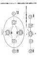
図1は、本発明の原理を説明するための図である。 FIG. 1 is a diagram for explaining the principle of the present invention.
本発明は、エンド(端末)Aとエンド(端末)Bの間で、IPネットワーク上のコンテンツ転送アプリケーションを実行するシステムで、該エンドAが直接または間接的に接続されたノードAと、該エンドBが直接または間接的に接続されたIPノード装置であるノードBと、該ノードAと該ノードBの間に、IPルーティングプロトコルもしくは、スタティックに設定された標準経路と、該ノードA、該ノードB間の該標準経路が使用するポートと別のポートを使用することで、実現可能な、該標準経路と異なるIP上の少なくとも1つ以上の経路と、を有するネットワークにおけるアプリケーションフロー経路制御方法において、
ノードA及びノードBが、
パケットの送り元IPアドレス、送り先のIPアドレス、プロトコル種別、送り元アプリケーションのポート番号、送り先アプリケーションのポート番号を含む制御対象フロー識別情報を予め記憶手段に格納しておき、
ルーティングやスイッチングを含む通常のノード動作を行うと共に、パケットをどのポートに出力するかを示すポート情報と、パケットヘッダを書き換えるための情報が記述されたエントリに基づいて、記憶手段に記憶されている制御対象フロー識別情報を参照して、パケットの出力を制御するパケット処理手段と、
エントリをソフトウェア的に書き換え可能なエントリメンテナンスソフトウェアと、
記憶手段の制御対象フロー識別情報に適合するパケットの指定した時間内の流量を積算及び数値を参照するモニタ手段と、を有する装置であるとき、
制御対象フロー識別情報の全てもしくは、一部に適合するヘッダを使用可能なパケットを、モニタ手段でモニタリングされた時間的平均流量とパケットサイズを指定して出力するパケット生成手段を、ノードAからノードBへのフローを制御する場合に、ノードAの入力ポートまたは、ノードA内部でソフトウェア的に生成する場合は、内部経路経由で前記パケット処理手段に接続し、
ノードAにおいて、
パケット生成手段の出力パケットのヘッダ情報のうち、IPアドレス部分を、アプリケーションフローの経路品質をモニタ対象のアプリケーションフローのヘッダ情報のIPアドレスに書き換え、該モニタ対象のアプリケーションフローが通過する経路のポートに出力し(ステップ1)、
ノードBにおいて、
ノードAのパケット生成手段で生成されたパケットを抽出し(ステップ2)、
モニタ手段にてパケットの流量を計算し(ステップ3)、予め設定された品質劣化状態を示す値と該流量を比較し(ステップ4)、比較した結果、品質劣化状態であると判断された場合に、エントリメンテナンスソフトウェアにおいて、所定のインタフェースを介して、ノードAのエントリのアプリケーションフローを指定するポート番号を含むエントリ情報を変更させ、出力ポートを別経路に対応するポートに変更させる(ステップ5)。The present invention relates to a system for executing a content transfer application on an IP network between an end (terminal) A and an end (terminal) B, a node A to which the end A is directly or indirectly connected, and the end A node B, which is an IP node device to which B is directly or indirectly connected, and an IP routing protocol or a statically set standard route between the node A and the node B, and the node A, the node In an application flow path control method in a network having at least one path on an IP different from the standard path, which can be realized by using a port different from the port used by the standard path between B ,
Node A and Node B are
Control target flow identification information including a packet source IP address, a destination IP address, a protocol type, a port number of a source application, and a port number of a destination application is stored in a storage unit in advance.
A normal node operation including routing and switching is performed, and port information indicating to which port a packet is output and information for rewriting the packet header are stored in the storage unit based on the entry in which information is described. Packet processing means for controlling the output of the packet with reference to the control target flow identification information;
Entry maintenance software that can rewrite entries in software,
When the device has the monitoring means for integrating the flow rate within the specified time of the packet that matches the control target flow identification information of the storage means and referring to the numerical value,
A packet generation unit that outputs a packet that can use a header that conforms to all or part of the control target flow identification information by designating a temporal average flow rate and a packet size monitored by the monitoring unit. In the case of controlling the flow to B, if it is generated by software in the input port of node A or inside node A, it is connected to the packet processing means via an internal path,
In node A,
Of the header information of the output packet of the packet generation means, the IP address portion is rewritten to the IP address of the header information of the application flow to be monitored by changing the route quality of the application flow to the port of the route through which the application flow to be monitored passes. Output (step 1)
In Node B,
Extract the packet generated by the packet generation means of node A (step 2),
When the flow rate of the packet is calculated by the monitoring means (step 3), the flow rate is compared with a preset value indicating the quality degradation state (step 4), and as a result of the comparison, it is determined that the quality degradation state is present In the entry maintenance software, the entry information including the port number for designating the application flow of the entry of the node A is changed through a predetermined interface, and the output port is changed to a port corresponding to another route (step 5). .
また、本発明は、ノードAにおいて、
パケット生成手段のパケットを複製し、
パケットを別経路に対応するポートに対しても出力し、
ノードBにおいて、
モニタ手段で、ノードAにおいて複製されたパケットを抽出し、品質劣化状態を計測し、当初の経路品質と計測された品質とを比較して、その結果により、エントリメンテナンスソフトウェアにおいて、該ノードAにおける対象フローのエントリにおける出力ポート及び、接続される該ノードBのポートからのアプリケーションフローを出力するポートを含むエントリを設定する。In the present invention, the node A
Duplicate the packet of the packet generation means,
Output the packet to the port corresponding to another route,
In Node B,
The monitoring means extracts the duplicated packet at the node A, measures the quality degradation state, compares the original route quality with the measured quality, and according to the result, in the entry maintenance software, at the node A An entry including an output port in the target flow entry and a port for outputting an application flow from the connected node B port is set.
また、本発明のノードA及びノードBのエントリは、
特定アプリケーションフローのペイロードあるいは、L7(レイヤ7)ヘッダを参照して動作を決定する記述とし、全てのアプリケーションフローをどちらかに属する2つの参照時のパターンを指定し、入射パケットがその一方に適合した場合に、通常経路にフォワードされるエントリ、もう一方に適用した場合に、別経路にフォワードされる番号を含むエントリ設定とする。Further, the entries of the node A and the node B of the present invention are as follows:
It is a description that determines the operation by referring to the payload of the specific application flow or the L7 (Layer 7) header, specifies two reference patterns that belong to either application flow, and the incident packet conforms to one of them In this case, the entry is set to include an entry forwarded to the normal route and a number forwarded to another route when applied to the other route.
また、本発明は、パケット生成手段を用いない場合に、
モニタ手段で測定・判定されるパケットの流量を、ノードBのポートへの入力パケットの実時間の総流量とし、品質劣化状態の比較の結果に対応する動作決定条件を、該総流量の情報と経路帯域に対する余裕度、もしくは、その一方から定める。In the present invention, when packet generating means is not used,
The packet flow rate measured and determined by the monitoring means is the total real-time flow rate of the input packet to the port of the node B, and the operation determination condition corresponding to the result of the quality degradation state comparison is the information on the total flow rate. It is determined from the margin for the path bandwidth or one of them.
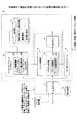
図2は、本発明の原理構成図である。 FIG. 2 is a principle configuration diagram of the present invention.
本発明は、エンド(端末)Aとエンド(端末)Bの間で、IPネットワーク上のコンテンツ転送アプリケーションを行うシステムで、該エンドAが直接または間接的に接続されたノードAと、該エンドBが直接または間接的に接続されたIPノード装置であるノードBと、該ノードAと該ノードBの間に、IPルーティングプロトコルもしくは、スタティックに設定された標準経路と、該ノードA、該ノードB間の該標準経路が使用するポートと別のポートを使用することで、実現可能な、該標準経路と異なるIP上の少なくとも1つ以上の経路と、を有するネットワークにおけるアプリケーションフロー経路制御システムであって、
ノードA及びノードBは、
パケットの送り元IPアドレス、送り先のIPアドレス、プロトコル種別、送り元アプリケーションのポート番号、送り先アプリケーションのポート番号を含む制御対象フロー識別情報を予め格納する記憶手段15と、
ルーティングやスイッチングを含む通常のノード動作を行うと共に、パケットをどのポートに出力するかを示すポート情報と、パケットヘッダを書き換えるための情報が記述されたエントリに基づいて、記憶手段に記憶されている制御対象フロー識別情報を参照して、パケットの出力を制御するパケット処理手段14と、
エントリをソフトウェア的に書き換えるエントリメンテナンスソフトウェア12と、
記憶手段の制御対象フロー識別情報に適合するパケットの指定した時間内の流量を積算及び数値を参照するモニタ手段13と、
ノードAの入力ポートに接続され、制御対象フロー識別情報の全てもしくは、一部に適合するヘッダを使用可能なパケットを、モニタ手段13でモニタリングされた時間平均流量とパケットサイズを指定して出力するパケット生成手段11と、を有し、
エントリメンテナンスソフトウェア12は、
パケット生成手段11の出力パケットのヘッダ情報のうち、アプリケーションフローの経路品質をモニタ対象のアプリケーションフローのヘッダ情報のIPアドレスを、ノードAのIPアドレスに書き換える手段を有し、
パケット処理手段14は、
モニタ対象のアプリケーションフローが通過する経路のポートに出力する手段を有し、
ノードBのモニタ手段13は、
ノードAに接続されたパケット生成手段11で生成されたパケットを抽出し、パケットの流量を計算し、予め設定された品質劣化状態を示す値と比較する手段を有し、
ノードBのエントリメンテナンスソフトウェア12は、
モニタ手段13で比較された結果、品質劣化状態であると判定された場合に、ノードAのエントリに対して、所定のインタフェースを用いて、アプリケーションフローを指定するポート番号を含むエントリ情報を変更させ、出力ポートを別経路に対応するポートに変更させる手段を有する。The present invention is a system for performing a content transfer application on an IP network between an end (terminal) A and an end (terminal) B, and a node A to which the end A is directly or indirectly connected, and the end B Node B, which is an IP node device directly connected or indirectly connected, and an IP routing protocol or a statically set standard route between the node A and the node B, and the node A and the node B An application flow routing control system in a network having at least one route on an IP different from the standard route, which can be realized by using a port different from the port used by the standard route between And
Node A and Node B are
A storage means 15 for preliminarily storing control target flow identification information including a packet source IP address, a destination IP address, a protocol type, a source application port number, and a destination application port number;
A normal node operation including routing and switching is performed, and port information indicating to which port a packet is output and information for rewriting the packet header are stored in the storage unit based on the entry in which information is described. Packet processing means 14 for controlling the output of the packet with reference to the control target flow identification information;
Monitoring means 13 for integrating the flow rate within a specified time of a packet that matches the control target flow identification information of the storage means and referring to a numerical value;
A packet that is connected to the input port of the node A and can use a header that matches all or part of the control target flow identification information is output by designating the time average flow rate and the packet size monitored by the monitoring means 13. Packet generating means 11;
The
A means for rewriting the IP address of the header information of the application flow to be monitored with respect to the path quality of the application flow in the header information of the output packet of the packet generation means 11 to the IP address of the node A;
The packet processing means 14
It has a means to output to the port of the route through which the application flow to be monitored passes,
The monitoring means 13 of the node B
A means for extracting a packet generated by the packet generation means 11 connected to the node A, calculating a flow rate of the packet, and comparing with a value indicating a preset quality degradation state;
Node B
When it is determined that the quality is in a degraded state as a result of the comparison by the
また、本発明のノードAのパケット処理手段は、
パケット生成手段で生成されたパケット複製する手段と、
パケットを別経路に対応するポートに対しても出力する手段を含み、
ノードBのモニタ手段は、
ノードAにおいて複製されたパケットを抽出し、品質劣化状態を計測し、当初の経路品質と計測された品質とを比較する手段を有し、
エントリメンテナンスソフトウェアは、
比較された結果により、該ノードAにおける対象のアプリケーションフローのエントリにおける出力ポート及び、接続される該ノードBのポートからのアプリケーションフローを出力するポートを含むエントリを設定する手段を含む。Further, the packet processing means of the node A of the present invention is:
Means for replicating the packet generated by the packet generation means;
Including means for outputting a packet to a port corresponding to another route;
Node B monitoring means:
Means for extracting a duplicated packet at node A, measuring a quality degradation state, and comparing the original path quality with the measured quality;
Entry maintenance software
According to the comparison result, a means for setting an entry including an output port in an entry of the target application flow in the node A and a port for outputting an application flow from the connected port of the node B is included.
また、本発明のノードAおよびノードBのエントリは、
特定アプリケーションフローのペイロードあるいは、L7(レイヤ7)ヘッダを参照して動作を決定する記述とし、全てのアプリケーションフローをどちらかに属する2つの参照時のパターンを指定し、入射パケットがその一方に適合した場合に、通常経路にフォワードされるエントリ、もう一方に適用した場合に、別経路にフォワードされる番号を含むエントリ設定とする。Further, the entries of the node A and the node B of the present invention are as follows:
It is a description that determines the operation by referring to the payload of the specific application flow or the L7 (Layer 7) header, specifies two reference patterns that belong to either application flow, and the incident packet conforms to one of them In this case, the entry is set to include an entry forwarded to the normal route and a number forwarded to another route when applied to the other route.
また、本発明は、パケット生成手段を用いない構成であるとき、
モニタ手段は、
測定・判定されるパケットの流量を、ノードBのポートへの入力パケットの実時間の総流量とし、品質劣化状態の比較の結果に対応する動作決定条件を、該総流量の情報と経路帯域に対する余裕度、もしくは、その一方から定める手段を含む。In addition, when the present invention is a configuration that does not use packet generation means,
The monitoring means
The flow rate of the packet to be measured / determined is the total real-time flow rate of the input packet to the node B port, and the operation decision condition corresponding to the result of the quality degradation state comparison is determined for the total flow rate information and the path bandwidth. Means for determining the margin or one of them is included.
本発明は、アプリケーション毎に異なる所要特性に対して、品質劣化を、アプリケーションに対応して観測し、品質劣化時にそのアプリケーションの特性改善が可能になる。 The present invention makes it possible to observe quality degradation corresponding to an application with respect to required characteristics that differ for each application, and to improve the characteristics of the application at the time of quality degradation.
また、そのときに他のアプリケーションフローに何ら影響を与えない。さらに、切替時に、そのフロー自体のトラヒックも付加的な欠落をせずに、端末に依存せず、ネットワークサイドでのネットワークの品質を改善できる。 In addition, other application flows are not affected at that time. Further, when switching, the traffic of the flow itself is not additionally lost, and does not depend on the terminal, so that the network quality on the network side can be improved.
結果として、ネットワークの有効利用、ネットワークを介したエンドへの良好なコンテンツ配信を行うことができる。 As a result, effective use of the network and good content distribution to the end via the network can be performed.
以下、図面と共に本発明の実施の形態を説明する。 Hereinafter, embodiments of the present invention will be described with reference to the drawings.
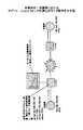
本発明は、図3に示すように、送信側のエンド(端末)Aと受信側のエンド(端末)Bの間で、IPネットワーク上のコンテンツ転送アプリケーションを行うシステムである。 As shown in FIG. 3, the present invention is a system that performs a content transfer application on an IP network between an end (terminal) A on the transmission side and an end (terminal) B on the reception side.
ノードA,ノードBは、IP(Internet Protocol)ノード装置であり、ノードAとノードBの間に、IPルーティングプロトコルもしくは、スタティックに設定された標準経路と、該ノードA,該ノードB間の該経路が使用するポートと別のポートを使用することで実現可能な、該経路と異なるIP上の少なくとも1つ以上の経路が存在する。これらのノード装置は、複数のインタフェースカードと、それらの制御を一括して管理する共通の部分を有する。各カードは、基本的に入力パケットを処理して出力ポートに出力する。 The node A and node B are IP (Internet Protocol) node devices, and an IP routing protocol or a statically set standard route between the node A and the node B, and the node between the node A and the node B There is at least one route on an IP different from the route that can be realized by using a port different from the port used by the route. These node devices have a plurality of interface cards and a common part that collectively manages their control. Each card basically processes an input packet and outputs it to an output port.
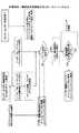
図4は、本発明の一実施の形態におけるノード装置の構成(その1)を示す。同図に示すノード装置は、ソフトウェアで構成されるエントリメンテナンスソフトウェア12、エントリ制御部18、パケット処理部14、ソフトウェアで構成されるモニタインタフェース13、入力ポート3、複数の出力ポート4、記憶部15から構成され、その外部にパケット生成器11、表示装置17が接続されている。 FIG. 4 shows the configuration (part 1) of the node device according to the embodiment of the present invention. The node device shown in the figure includes an
パケット生成器11は、ノード装置10の入力ポート3に接続され、モニタのために使用するパケットを生成し、入力ポート3に出力する。 The
記憶部15には、予め、制御対象フロー識別情報(L3,L4ヘッダ情報、ペイロード情報)と、切り替え時に経路を指定するための経路情報及び、モニタインタフェース13から得られたモニタ情報を参考に切り替えるかを決定するための切り替え条件を格納しておき、エントリメンテナンスソフトウェア12のノード装置制御アプリケーション121がそれぞれの動作の際に参照する。 The
エントリ制御部18は、物理的にはメモリデバイスで構成され、ルーティングやスイッチングを含む通常のノード動作を行うと共に、パケットをどのポートに出力するかを示すポート情報と、パケットヘッダを書き換えるためのエントリを有し、エントリメンテナンスソフトウェア12で書き換えられたエントリの処理命令をパケット処理部14に渡す。 The
エントリメンテナンスソフトウェア12は、ノード装置制御アプリケーション121とエントリ書き換えようインタフェース(CLI,API)を有する。パケット生成器11からの入力パケットに基づいて、エントリ制御部18内のエントリの内容をソフトウェア的に書き換える。詳しくは、モニタインタフェース16において、計算された流量と予め設定された品質劣化状態を示す値とを比較し、比較した結果、品質劣化状態であると判定された場合に、エントリ制御部18のアプリケーションフローを指定するポート番号を含むエントリ情報を、エントリ書き換え用インタフェース122を用いて変更し、出力ポートを別経路に対応するポートに変更するようにノード装置制御アプリケーション121を用いて制御する。ここで、ノード装置制御アプリケーション121は、モニタインタフェースからデータを取得し、記憶部15に記憶されている情報を参照して、取得データにより制御の要否を判断して必要であれば、エントリ書き換えようインタフェース122を経由して制御する。 The
パケット処理部14は、パケット複製部141とパケット流量積算部142を有し、パケット生成器11で生成されたパケットを抽出し、バッファに一時的に格納すると共に、エントリ制御部18からの処理命令信号によりパケットを処理し、パケットを経路(出力ポート4)に出力する。当該パケット処理部14が送信側で動作する場合には、パケット生成器11からの出力パケットのヘッダ情報のうち、IPアドレス部分を、アプリケーションフローの経路品質をモニタ対象のフローのヘッダ情報のIPアドレスに書き換え、モニタ対象のアプリケーションフローが通過する経路の出力ポートに出力する。また、パケット処理部14は、パケット生成器11から出力されたパケットをパケット複製部141で複製し、別経路に対応する出力ポート4に対しても出力する。また、当該パケット処理部14が受信側で動作する場合には、送信側ノード装置のパケット生成器11で生成されたパケット抽出する。 The
モニタインタフェース16は、表示装置17に対して、記憶部15の制御対象フロー識別情報を渡すと共に、モニタ結果を読出し、表示する。 The
なお、上記のノード装置10は、複数のカードスロットを有し、ネットワークインタフェースカード(もしくはモジュール)という形態で複数枚実装されるものとする。 The
なお、別のノード装置の構成として図5に示すような構成も可能である。図5に示す構成は、モニタ部16がモニタインタフェース13に接続され、当該モニタ部16に記憶部15が接続されている。図5に示す構成では、ネットワークを介してもモニタインタフェース13とモニタ部16を接続し、モニタ部16において、モニタリングと切替判断を行う。その結果をノード装置10に渡す。同図の構成の場合は、ノード装置制御アプリケーション121は主として使用せず、CLIなどのインタフェース122により、モニタ部16が処理にかかわる指示を行う。 A configuration as shown in FIG. 5 is also possible as a configuration of another node device. In the configuration shown in FIG. 5, the
ここで、上記の図4における動作を説明する。 Here, the operation in FIG. 4 will be described.
送信側のノードAのパケット処理部14において、入力ポート3を介して取得したパケット生成器11の出力パケットのヘッダ情報のうち、IPアドレス部分を、モニタインタフェース13から取得したアプリケーションフローの経路品質をモニタ対象のフローのヘッダ情報のIPアドレスに書き換え、モニタ対象のフローが通過する経路の出力ポート4に出力する。 In the
受信側のノードBのパケット処理部14において、ノードAのパケット生成器11で生成されたパケットを抽出し、パケット処理部14のパケット流量積算部142で流量を計算し、予め設定した品質劣化状態を示す値と当該流量を比較し、比較した結果、品質劣化状態であると判定された場合に、エントリメンテナンスソフトウェア12において、ノードAのエントリのアプリケーションフローを指定するポート番号を含むエントリ情報を変更させ、出力ポートを別経路に対応するポートに変更させる。なお、ノードBにおいて、ノードAのエントリを変更する場合、ノードB及びノードAのエントリ書き換え用インタフェース122を用いて行う。なお、ノードA,Bを管理する別の装置において、ノードBにおけるモニタ結果を当該装置に送信し、当該装置からノードAまたはノードBに対してエントリの書き換えを指示することも考えられる。 In the
また、ノードAのパケット複製部141でパケットが複製されて出力されている場合は、ノードBのパケット処理部14は、その複製されたパケットを抽出し、モニタインタフェース16でモニタリングする。 When a packet is duplicated and output by the
前述の図3において、(a)は、ネットワーク構成を示し、同図(b)は、品質劣化発生場所を示す。 In FIG. 3 described above, (a) shows the network configuration, and (b) in FIG.
エンドツーエンド間のネットワークに、IPリーチャブルな複数経路が存在するマルチキャストホーム環境において、その入出力ポートを指定することで、複数の経路が切り替え可能な位置に指定する機能を有するルータ等のノード装置を配置する。そして、通常使用しているネットワーク経路が、障害というよりも品質劣化状態になる、という状況を想定している。即ち、図3(b)のような状況である。ここで、品質としては特定のアプリケーションに対するものを想定している。 A node device such as a router having a function of designating a position where a plurality of routes can be switched by designating the input / output port in a multicast home environment where a plurality of IP reachable routes exist in an end-to-end network Place. It is assumed that the network path that is normally used is in a quality degradation state rather than a failure. That is, the situation is as shown in FIG. Here, the quality is assumed to be for a specific application.
前述の図4において、ノード装置10は、ルーティングやスイッチなど通常のノード動作をすると共に、パケットの送り元IPアドレス、送り先(受信)のIPアドレス、TCPかUDP(User Datagram Protocol)かのプロトコル種別、送り元アプリケーションのポート番号、送り先(受信)アプリケーションのポート番号を参照し、指定したものと一致した場合、指定するポートに、指定するヘッダを記載して出力するパケット処理部14を有する。即ち、この動作を記述するエントリには、
・パケットをどのポート(ノード装置に収容されているインタフェース)に出力するかのポートに関する情報;
・パケットヘッダを書き換える内容である、送り元IPアドレス、送り先(受信)のIPアドレス、TCPかUDPかのプロトコル種別、送り元アプリケーションのポート番号、送り先(受信)アプリケーションのポート番号;
と、を記述する。In FIG. 4 described above, the
-Information about the port to which the packet (interface accommodated in the node device) is output;
The contents of rewriting the packet header, the source IP address, the destination (reception) IP address, the protocol type of TCP or UDP, the port number of the source application, the port number of the destination (reception) application;
And describe.
このエントリは、ノード装置上に実現されたソフトウェアで構成されるエントリメンテナンスソフトウェア12から書き換え可能な構成とする。このエントリを、2つのノード装置で書き換えることにより、マルチキャストホームのIPレイヤでの切り替えが可能になる。 This entry is configured to be rewritable from the
当該ノード装置上、もしくは、ノード装置に接続された別のハードウェア上には、入力されたフレームもしくは、パケットペイロードサイズを積算するパケット流量積算手段(装置)を設ける。これにより、切り替え条件により、アプリケーション、つまりポート番号まで指定されたパケットの流量が観測可能となる。この計算のための読出し機構は、モニタインタフェース13としてソフトウェア的に実装する。 On the node device or another hardware connected to the node device, a packet flow rate integration means (device) for integrating the input frame or packet payload size is provided. Thereby, the flow rate of the packet designated up to the application, that is, the port number can be observed according to the switching condition. The readout mechanism for this calculation is implemented as software as the
図6は、本発明の一実施例のアプリケーショントラヒックの測定のモニタ動作を示す。図4の構成では、フレームまたは、パケットペイロードサイズの積算は、パケット処理部14のパケット流量積算部142で行うものとし、読出しは、モニタインタフェース16行う例を示しているが、パケット流量積算をノード装置10に接続されるハードウェアで行い、読出しはソフトウェア(モニタインタフェース16)で行うようにしてもよく、現時点のハードウェア、CPU能力等から、1msec程度の分解能実時間測定可能である。図6では、ノードAにおいて、ノード装置10に接続されるハードウェアのモニタ装置において、送信・宛先アドレス、送信・宛先ポート番号を指定し、一致したアプリケーションフローの流量を積算し、ソフトウェアであるモニタインタフェース16によりこれを読出し、表示装置に表示した例を示している。 FIG. 6 shows the monitoring operation of the application traffic measurement according to the embodiment of the present invention. In the configuration of FIG. 4, the frame or packet payload size is accumulated by the packet flow
また、図7に示すように、特定のストリーム配信など、ある方向に関して品質を監視する場合など、少なくとも片方のノード装置には、当該方向に指定する時間分布、パケットサイズ、流量でパケットを送出可能なパケット生成器11を接続する。 In addition, as shown in FIG. 7, when monitoring quality in a certain direction, such as for specific stream delivery, packets can be sent to at least one node device with the time distribution, packet size, and flow rate specified in that direction. The
これにより、上記のノード装置10、モニタ装置と共に用いることにより、注目するアプリケーションフローの現在の品質がモニタ可能となる。 As a result, the current quality of the application flow of interest can be monitored by using the
また、図8に示すように、モニタ装置をモニタ部13としてノード装置10に内蔵するように構成してもよい。その場合、前述の図4に示すモニタインタフェース13は、不要となり、モニタ部13でモニタリングされた流量等の品質を当該モニタ部13から表示装置17に直接表示することが可能である。ノード装置10に内蔵されるパケット生成器11は、例えば、時間的に一定間隔の均一トラヒックを生成し、パケット処理部14に入射する。このとき、注目するアプリケーションが使用しているパケット・フレームサイズを用いる。ノード装置10は、生成されたパケットを、注目するアプリケーションフローと同一ポートに出力する。この際、ノードAでは、ポート番号は別途指定し、他の送信元IPアドレス、受信IPアドレス等は、同一のパケットに書き換えする。こうすると、ポート番号だけが異なる測定用パケットが、注目しているアプリケーションフローと同一の経路・環境でフォワーディングされる。また、パケット・フレームサイズを同一にすることで、フレームサイズ等によって動作が異なる場合のあるルータ等の影響を同一にできる。ノードBでは、別途指定したポート番号まで指定し、そのフローのトラヒック量をパケット処理部14のパケット流量積算部142で積算し、モニタ部13で積算量を表示装置17に表示することにより監視している。フローのトラヒック情報のデータに応じて、ある値以下になった場合、というように条件を与えることにより、制御アプリケーションもしくは、外付けの場合ではモニタ部が、品質劣化を判断することが可能となる。 Further, as shown in FIG. 8, the monitor device may be built in the
また、経路品質河ポート番号まで依存することが予想される場合は、ヘッダ参照条件としてペイロード(の一部)もしくは、アプリケーションが使用するヘッダ的情報であるL7(レイヤ7)まで参照可能なものを用いる。パケットサイズに関しては、必ずしもパケットサイズが予想されない場合は、中間的なもの、あるいは典型的なもの、測定して最も多かったものを用いる方法、あるいは、複数種のパケット・フレームサイズのパケットを混ぜることで平均化した値を得る方法が考えられる。パケット間隔に関しては、等間隔の他、バースト的な時間分布とし、モニタ間でその広がりの程度を観測することで、ジッダに対する品質基準とすることが可能である。 In addition, when it is expected to depend on the route quality river port number, the header reference condition can be referred to the payload (part of) or L7 (layer 7) which is header information used by the application. Use. Regarding the packet size, if the packet size is not always expected, use the intermediate or typical one, the method using the one that has been measured the most, or mix the packets of multiple packet frame sizes It is conceivable to obtain a value averaged by. As for the packet interval, it is possible to set the quality standard for the jedder by observing the extent of the spread between the monitors in addition to the equal interval and the burst time distribution.
図9は、本発明の一実施例の制御動作のフローチャート(その1)であり、通常経路の品質のみをモニタリングし、品質劣化自に経路2に切り替える場合を示している。ここでは、通常経路をモニタリングし、品質劣化自に、他の経路に切り替える。この際、他の経路の品質を予めモニタリングすることはしていない。同図の例では、ノードAからノードBへの流れのみを対象とする。そのため、ノードの設定は、先にノードBを完了させる(ノードBの経路2経由時のアプリケーションフローのフォワーディングエントリを設定する)(ステップ101)。この設定が完了していることで(ステップ102、Yes)、実際に切り替えになったとき、ノードAのみで動作切り替えが可能であり、通信断の状態が発生しない。 FIG. 9 is a flowchart (No. 1) of the control operation of the embodiment of the present invention, and shows a case where only the quality of the normal route is monitored and the quality deterioration is switched to the route 2 itself. Here, the normal route is monitored, and the quality deterioration itself is switched to another route. At this time, the quality of other routes is not monitored in advance. In the example of the figure, only the flow from the node A to the node B is targeted. Therefore, the node is set first by completing the node B (setting the forwarding entry of the application flow when passing through the route 2 of the node B) (step 101). When this setting is completed (
このときの動作は、通常経路の品質が指定値以下かどうかをモニタリングし(ステップ103)、以下(劣化あり)の場合に(ステップ104、Yes)、ノードAのエントリを書き換える(ステップ105,106)。この切り替えは、当該アプリケーションが終了した後、エントリから削除する。 The operation at this time is to monitor whether or not the quality of the normal route is below the specified value (step 103), and if it is below (with deterioration) (
図10は、本発明の一実施例の制御動作のフローチャート(その2)であり、通常経路、別経路の両方をモニタリングし、品質劣化時に、良好な方に切り替える場合を示している。通常経路(経路1)、経路2のそれぞれに対して、図6に示した方法により、品質をモニタリングしておく。複数の経路に対してモニタリングする場合は、品質モニタ測定用プローブパケットは、ノード装置Aの複数ポートから出力する必要がある。この場合は、ノードAによって、パケット生成器11からの入力パケットを複製するエントリを記述し、複製し(ステップ201)、経路1、経路2に対応するポートに出力する(ステップ202)。ノード装置Bでは、経路1、経路2に対応する入力ポートに、測定用パケットのエントリを記述し(ステップ203)、モニタリングすることで、両経路の同時モニタリングを行う(ステップ205)。これにより、通常経路がある品質レベル以下になり、かつ、経路2が通常経路のレベル以上あるいは、所定品質レベル以上の場合に(ステップ206,Yes)切り替え(ステップ207)、さらに、経路2が品質劣化した場合に(ステップ208)、経路1に切り替える(ステップ209)。 FIG. 10 is a flowchart (part 2) of the control operation of the embodiment of the present invention, and shows a case where both the normal route and the different route are monitored and switched to the better one when quality deteriorates. Quality is monitored for each of the normal route (route 1) and route 2 by the method shown in FIG. When monitoring a plurality of paths, the quality monitor measurement probe packet needs to be output from a plurality of ports of the node device A. In this case, an entry for duplicating the input packet from the
図11、図12は、本発明の一実施例におけるエントリの記述例を示す。図11は、図9の動作に対応するものであり、通常経路のみモニタリングし、切替動作を行う場合の例を示しており、図12は、図10の動作に対応するものであり、両経路をモニタリングする場合の例を示している。 11 and 12 show an example of entry description in one embodiment of the present invention. 11 corresponds to the operation of FIG. 9 and shows an example in which only the normal route is monitored and the switching operation is performed. FIG. 12 corresponds to the operation of FIG. An example in the case of monitoring is shown.
図9の方法は、共用の予備経路など、モニタリング等せずとも比較的品質が安定している経路が使用可能なときに有効であり、図10の方法は、経路数によらず使用可能である。 The method of FIG. 9 is effective when a route with relatively stable quality can be used without monitoring or the like, such as a shared backup route, and the method of FIG. 10 can be used regardless of the number of routes. is there.
図13は、本発明の一実施例のL7参照動作とモニタリングを説明するための図である。ここでは、ノード装置Aは、L7(レイヤ7)の情報、例えば、アプリケーションヘッダなどを参照する。ここで簡便な記述のためにL7としているが、ペイロード(の一部)、もしくはL7の情報という意味であり、アプリケーションフローを複数のフローに分類できる参照情報である。以下、L7は、その主旨で使用している。論理的には、ノード装置Aは、特定アプリケーションフローに対して、さらに、L7情報を参照する。そのエントリには、L7情報がある値であれば経路1に、別の値であれば経路2に出力するエントリを記述する。その条件を選択することで、例えば、半分ずつ振り分けることや、4分の1を経路1、残りの4分の3を経路2に振り分ける。この際、切替条件として、当該アプリケーションフローの全てが経路1か経路2のどちらかに振り分けられるように記述する。 FIG. 13 is a diagram for explaining L7 reference operation and monitoring according to an embodiment of the present invention. Here, the node apparatus A refers to L7 (layer 7) information, such as an application header. Here, L7 is used for simple description, but it means payload (part) or information of L7, and is reference information that can classify application flows into a plurality of flows. Hereinafter, L7 is used for the purpose. Logically, the node device A further refers to the L7 information for the specific application flow. In the entry, an entry to be output to the
例えば、[論理和=真]になるようにすれば可能である。これにより、例えば、アプリケーションフロー自体が高速広帯域の場合で、他の経路にトラヒックを部分的に迂回することができる。前述の実施の形態における、L4までの動作では、大きな帯域を使用している指定したアプリケーションフロー全体を経路2に迂回させざるを得なかったが、この点を解決することができ、1つの経路を複数のアプリケーションで共用するといった有効活用が可能となる。 For example, it is possible to make [logical sum = true]. Thereby, for example, when the application flow itself is a high-speed and wideband, traffic can be partially bypassed to another route. In the operation up to L4 in the above-described embodiment, the entire designated application flow using a large bandwidth has to be diverted to the path 2, but this point can be solved and one path It is possible to effectively utilize such as sharing with multiple applications.
図14にその際の動作のフローチャートを示す。同図では、L7の通常経路の品質のみをモニタリングし、品質劣化時に、経路2に振り分ける場合の動作を示す。同図のフローチャートは、前述の図9のフローとほぼ同様であるが、L7参照条件を使用する点で異なる。また、図10に対するような動作も可能である。 FIG. 14 shows a flowchart of the operation at that time. In the figure, only the quality of the L7 normal route is monitored, and the operation is performed when the quality is deteriorated and assigned to the route 2. The flowchart in FIG. 9 is substantially the same as the flow in FIG. 9 described above, but differs in that the L7 reference condition is used. Further, an operation as shown in FIG. 10 is also possible.
図15は、本発明の一実施例のエントリの記述例を示しており、L7動作をする場合の例である。 FIG. 15 shows a description example of an entry according to an embodiment of the present invention, which is an example when an L7 operation is performed.
図16は、本発明の一実施例の制御動作のフローチャートであり、通常経路のトラヒック量をモニタリングし、帯域の余裕がなくなったとき、経路2に振り分ける場合の動作を示す。このとき、動作条件として、通常経路のトラヒック的な余裕度を用い、通常経路の余裕度に応じて、L7動作での経路切り替えを行うか判断する。 FIG. 16 is a flowchart of a control operation according to an embodiment of the present invention, and shows an operation in the case of monitoring the traffic amount of the normal route and allocating to the route 2 when there is no more bandwidth. At this time, the traffic-like margin of the normal route is used as the operation condition, and it is determined whether or not the route switching in the L7 operation is performed according to the margin of the normal route.
次に、ノード装置の構成について説明する。 Next, the configuration of the node device will be described.
図17は、本発明の一実施例のノード装置の詳細な構成を示す。 FIG. 17 shows a detailed configuration of a node device according to an embodiment of the present invention.
同図に示すノード装置は、(a)が動作エンジンであり、それを(b)に示すように、複数枚搭載してノード装置を構成している。同図(a)では、処理内容デコーダ22が前述のエントリ制御部18のエントリであり、参照条件と適合した場合の動作が記述してある。これは、同図(b)に示すように、コンパクトPCIパス41を通じてホストMPU42と接続され、ソフトウェア的に可変であり、記述を変更できる。同図(a)パケット情報抽出回路で、入力パケットのヘッダ抽出、さらには、L7情報の抽出を行い、処理内容デコーダ22で条件を参照し、処理命令信号(出力ポートや、ヘッダ書き換え有無、複製の要否)とそれに関わるデータを、パケット処理エンジン23に渡す。パケットは、バッファ24を介して、パケット処理エンジン23に入力されるので、このデータに対して処理を行い、所定のパケットが得られることになる。処理内容デコーダ22の書き換えが行われる場合には、現在パケット入力後、その処理中に行われ、次パケット到着前に完了する。従って、エントリ(処理内容デコーダ22)上の空白時間はなく、切替動作によるパケット損失は発生しない。 In the node apparatus shown in FIG. 3, (a) is an operation engine, and as shown in (b), a plurality of nodes are mounted to constitute a node apparatus. In FIG. 9A, the
また、同図では、インタフェースとして、GbE42,コンパクトPCIパス41等を使用した例を示しているが、これらは一例であり、他のインタフェースを使用することも可能である。 Moreover, although the example which used GbE42, the compact PCI path 41, etc. as an interface is shown in the same figure, these are examples and can also use another interface.
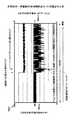
図18は、本発明の一実施例の品質モニタリングの動作を説明するための図であり、図17に示すノード装置を用いた場合の例である。図18において、aは、全トラヒックから抽出されたアプリケーションフローを示しており、縦軸の右側の目盛を参照することにより品質劣化していることがわかる。また、bは、全トラヒックを示しており、縦軸の左側の目盛を参照することにより、パケットロスやジッダ等による品質劣化が生じた小容量のアプリケーションフローが含まれている。 FIG. 18 is a diagram for explaining the operation of quality monitoring according to an embodiment of the present invention, and is an example when the node device shown in FIG. 17 is used. In FIG. 18, a indicates an application flow extracted from all traffic, and it can be seen that the quality deteriorates by referring to the scale on the right side of the vertical axis. In addition, b indicates all traffic, and includes a small-capacity application flow in which quality degradation due to packet loss, jedder, or the like occurs by referring to the scale on the left side of the vertical axis.
高速帯域(〜1Gb)の中、特定のアプリケーションフロー(モニタリング用のプローブフローなどに対応)が抽出され、トラヒック量が実時間観測され、品質劣化した場合、その状態を確認できる。図18中、bの線が全トラヒックのモニタ結果であり、実時間モニタリングが可能であるが、品質劣化しているのが一部に対してあるため、大きな変化は見られない。特定のアプリケーションフローに対しては、経路上で品質劣化している。図18中、bの線がその様子であり、品質劣化による流量の変化が観測されている。このようにモニタリングすることで、高速な背景トラヒックの中で、アプリケーションフローの品質が異なる場合があるが、その品質が測定される。 When a specific application flow (corresponding to a monitoring probe flow or the like) is extracted from the high-speed band (up to 1 Gb), the traffic amount is observed in real time, and the quality can be confirmed. In FIG. 18, the line b is the monitoring result of all traffic, and real-time monitoring is possible. However, since there is a part in which quality is degraded, no significant change is observed. For a specific application flow, quality is degraded on the route. In FIG. 18, the line b shows the state, and a change in the flow rate due to quality degradation is observed. By monitoring in this way, the quality of the application flow may differ in high-speed background traffic, but the quality is measured.
図19は、本発明の一実施例の切替動作を行った場合の状態を示す図である。同図中aは経路1での品質劣化発生タイミングを示し、bはアプリケーションフローの切替タイミングを示し、gは、パケット廃棄なし時間区間を示し、hは経路1で15%のパケット廃棄の発生する時間区間を示し、fは、双方向の矢印で示される区間が経路1で品質劣化が生じた後、経路2への切替がなされるまでの時間を示している。cは、切替動作を行った場合の全トラヒックの動作であり、トラヒック全体が品質劣化している対象アプリケーションフロー以外には切り替えは影響を及ぼしていないことがわかる。dは、特定アプリケーションの動作であり、アプリケーションフローを経路2に切り替えることで、品質劣化前の経路1で得られていたトラヒックに回復していることがわかる。この動作により、全体は、品質劣化のままであるが、特定アプリケーションに対しては、品質回復していることがわかる。 FIG. 19 is a diagram showing a state when the switching operation of the embodiment of the present invention is performed. In the figure, “a” indicates the quality degradation occurrence timing in the
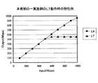
図20は、本発明の一実施例のL7動作時の特性例である。当該アプリケーションを標準で550Mbps程度の帯域の経路にフォワードしている。L4(もしくはL3)参照のみのフォワーディングでは、スループットは、この経路の帯域に制限されている。一方、別経路を用意し、L7を参照し、半分ずつのトラヒックを分散した。これにより、L4では確保できなかった帯域を確保することができていることがわかる。これにより、例えば、550Mbpsの帯域が埋まってきたとき、この経路振り分けを利用することで、品質改善、もしくは品質劣化の発生の回避ができることがわかる。 FIG. 20 is a characteristic example during L7 operation of one embodiment of the present invention. The application is forwarded to a route having a bandwidth of about 550 Mbps as a standard. In forwarding with reference only to L4 (or L3), the throughput is limited to the bandwidth of this path. On the other hand, another route is prepared, L7 is referred to, and half of the traffic is distributed. As a result, it is understood that the bandwidth that could not be secured by L4 can be secured. As a result, for example, when the bandwidth of 550 Mbps is filled, it is understood that the use of this route distribution can improve the quality or avoid the occurrence of the quality deterioration.
なお、本発明は、上記の実施の形態及び実施例に限定されることなく、特許請求の範囲内において、種々変更・応用が可能である。 The present invention is not limited to the above-described embodiments and examples, and various modifications and applications are possible within the scope of the claims.
本発明は、コンテンツを格納したコンテンツサーバから、ユーザがネットワークを介して閲覧するための、ネットワーク構成技術のネットワーク品質制御技術におけるアプリケーションフロー制御に適用できる。 The present invention can be applied to application flow control in a network quality control technique of a network configuration technique that allows a user to browse through a network from a content server that stores content.
3 入力ポート
4 出力ポート
10 ノード装置
11 パケット生成手段、パケット生成器
12 エントリメンテナンスソフトウェア
13 モニタ手段、モニタ装置、モニタ部
14 パケット処理手段、パケット処理部
15 記憶手段、記憶部
16 モニタインタフェース
17 表示装置
18 エントリ、エントリ制御部
20 処理機構(ハードウェア)
21 パケット情報抽出回路
22 処理内容デコーダ
23 パケット処理エンジン
24 バッファ
30 管理機構(ソフトウェア)
41 コンパクトPCIバス
42 ホストMPU
43 フルメッシュバックプレーン
44 GbE
121 ノード装置アプリケーション
122 エントリ書き換え用インタフェース
141 パケット複製部
142 パケット流量積算部3
21 packet
41
43
121
Claims (8)
Translated fromJapanese前記ノードA及び前記ノードBが、
パケットの送り元IPアドレス、送り先のIPアドレス、プロトコル種別、送り元アプリケーションのポート番号、送り先アプリケーションのポート番号を含む制御対象フロー識別情報を予め記憶手段に格納しておき、
ルーティングやスイッチングを含む通常のノード動作を行うと共に、パケットをどのポートに出力するかを示すポート情報と、パケットヘッダを書き換えるための情報が記述されたエントリに基づいて、前記記憶手段に記憶されている前記制御対象フロー識別情報を参照して、パケットの出力を制御するパケット処理手段と、
前記エントリをソフトウェア的に書き換え可能なエントリメンテナンスソフトウェアと、
前記記憶手段の前記制御対象フロー識別情報に適合するパケットの指定した時間内の流量を積算及び数値を参照するモニタ手段と、を有する装置であるとき、
前記制御対象フロー識別情報の全てもしくは、一部に適合するヘッダを使用可能なパケットを、前記モニタ手段でモニタリングされた時間的平均流量とパケットサイズを指定して出力するパケット生成手段を、ノードAからノードBへのフローを制御する場合に、ノードAの入力ポート、または、ノードA内部でソフトウェア的に生成する場合には、内部経路経由で前記パケット処理手段に接続し、
前記ノードAにおいて、
前記パケット生成手段の出力パケットのヘッダ情報のうち、IPアドレス部分を、アプリケーションフローの経路品質をモニタ対象のアプリケーションフローのヘッダ情報のIPアドレスに書き換え、該モニタ対象のアプリケーションフローが通過する経路のポートに出力し、
前記ノードBにおいて、
前記ノードAの前記パケット生成手段で生成されたパケットを抽出し、
前記モニタ手段にて前記パケットの流量を計算し、予め設定された品質劣化状態を示す値と該流量を比較し、比較した結果、品質劣化状態であると判断された場合に、前記エントリメンテナンスソフトウェアにおいて、所定のインタフェースを介して、前記ノードAのエントリのアプリケーションフローを指定するポート番号を含むエントリ情報を変更させ、出力ポートを別経路に対応するポートに変更させる、ことを特徴とするアプリケーションフロー経路制御方法。In a system that executes a content transfer application on an IP network between an end (terminal) A and an end (terminal) B, the node A to which the end A is directly or indirectly connected and the end B directly or An indirectly connected IP node device, Node B, and an IP routing protocol or a statically set standard route between the node A and the node B, and the node A and the node B In an application flow route control method in a network having at least one route on an IP different from the standard route, which can be realized by using a port different from the port used by the standard route,
The node A and the node B are
Control target flow identification information including a packet source IP address, a destination IP address, a protocol type, a port number of a source application, and a port number of a destination application is stored in a storage unit in advance.
A normal node operation including routing and switching is performed, and port information indicating which port the packet is output to and information for rewriting the packet header are stored in the storage unit based on an entry in which information is described. Packet processing means for controlling output of the packet with reference to the control target flow identification information,
Entry maintenance software capable of rewriting the entry in software;
When the device has a monitoring unit that integrates the flow rate within a specified time of the packet that matches the control target flow identification information of the storage unit and refers to a numerical value,
A packet generation unit that outputs a packet that can use a header that matches all or part of the control target flow identification information by designating a temporal average flow rate and a packet size monitored by the monitoring unit; To control the flow from node B to node B, if it is generated by software in the input port of node A or in node A, it connects to the packet processing means via an internal path,
In node A,
Of the header information of the output packet of the packet generating means, the IP address portion is rewritten to the IP address of the header information of the application flow to be monitored, and the port of the route through which the application flow to be monitored passes Output to
In the Node B,
Extracting the packet generated by the packet generation means of the node A;
The entry maintenance software calculates the flow rate of the packet by the monitoring means, compares the flow rate with a value indicating a preset quality degradation state, and determines that the quality degradation state is determined as a result of comparison. And changing the entry information including the port number specifying the application flow of the entry of the node A via a predetermined interface, and changing the output port to a port corresponding to another route. Routing method.
前記パケット生成手段のパケットを複製し、
前記パケットを前記別経路に対応するポートに対しても出力し、
前記ノードBにおいて、
前記モニタ手段で、前記ノードAにおいて複製された前記パケットを抽出し、品質劣化状態を計測し、当初の経路品質と計測された品質とを比較して、その結果により、前記エントリメンテナンスソフトウェアにおいて、該ノードAにおける対象フローのエントリにおける出力ポート及び、接続される該ノードBのポートからのアプリケーションフローを出力するポートを含むエントリを設定する、請求項1記載のアプリケーションフロー経路制御方法。In node A,
Duplicating the packet of the packet generation means,
Output the packet to the port corresponding to the different route,
In the Node B,
In the monitoring means, the packet duplicated in the node A is extracted, the quality degradation state is measured, the initial path quality is compared with the measured quality, and the result is used in the entry maintenance software. The application flow path control method according to claim 1, wherein an entry including an output port in an entry of a target flow in the node A and a port for outputting an application flow from the connected port of the node B is set.
特定アプリケーションフローのペイロードあるいは、L7(レイヤ7)ヘッダを参照して動作を決定する記述とし、全てのアプリケーションフローをどちらかに属する2つの参照時のパターンを指定し、入射パケットがその一方に適合した場合に、通常経路にフォワードされるエントリ、もう一方に適用した場合に、別経路にフォワードされる番号を含むエントリ設定とする請求項1記載のアプリケーションフロー経路制御方法。The entries for node A and node B are:
It is a description that determines the operation by referring to the payload of a specific application flow or the L7 (Layer 7) header, specifies two reference patterns that belong to either application flow, and the incident packet matches one of them. The application flow path control method according to claim 1, wherein the entry setting includes an entry forwarded to a normal path in the case of an entry and a number forwarded to another path when applied to the other path.
前記モニタ手段で測定・判定されるパケットの流量を、前記ノードBのポートへの入力パケットの実時間の総流量とし、品質劣化状態の比較の結果に対応する動作決定条件を、該総流量の情報と経路帯域に対する余裕度、もしくは、その一方から定める請求項1記載のアプリケーションフロー制御方法。When not using the packet generation means,
The flow rate of the packet measured / determined by the monitoring means is the total real-time flow rate of the input packet to the port of the Node B, and the operation determining condition corresponding to the result of the quality degradation state comparison is The application flow control method according to claim 1, wherein the application flow control method is determined from a margin for information and a path bandwidth, or one of them.
前記ノードA及び前記ノードBは、
パケットの送り元IPアドレス、送り先のIPアドレス、プロトコル種別、送り元アプリケーションのポート番号、送り先アプリケーションのポート番号を含む制御対象フロー識別情報を予め格納する記憶手段と、
ルーティングやスイッチングを含む通常のノード動作を行うと共に、パケットをどのポートに出力するかを示すポート情報と、パケットヘッダを書き換えるための情報が記述されたエントリに基づいて、前記記憶手段に記憶されている前記制御対象フロー識別情報を参照して、パケットの出力を制御するパケット処理手段と、
前記エントリをソフトウェア的に書き換えるエントリメンテナンスソフトウェアと、
前記記憶手段の前記制御対象フロー識別情報に適合するパケットの指定した時間内の流量を積算及び数値を参照するモニタ手段と、
前記ノードAの入力ポートに接続され、前記制御対象フロー識別情報の全てもしくは、一部に適合するヘッダを使用可能なパケットを、前記モニタ手段でモニタリングされた時間平均流量とパケットサイズを指定して出力するパケット生成手段と、を有し、
前記エントリメンテナンスソフトウェアは、
前記パケット生成手段の出力パケットのヘッダ情報のうち、アプリケーションフローの経路品質をモニタ対象のアプリケーションフローのヘッダ情報のIPアドレスを、前記ノードAのIPアドレスに書き換える手段を有し、
前記パケット処理手段は、
前記モニタ対象のアプリケーションフローが通過する経路のポートに出力する手段を有し、
前記ノードBの前記モニタ手段は、
前記ノードAに接続されたパケット生成手段で生成されたパケットを抽出し、パケットの流量を計算し、予め設定された品質劣化状態を示す値と比較する手段を有し、
前記ノードBのエントリメンテナンスソフトウェアは、
前記モニタ手段で比較された結果、品質劣化状態であると判定された場合に、前記ノードAのエントリに対して、所定のインタフェースを用いて、アプリケーションフローを指定するポート番号を含むエントリ情報を変更させ、出力ポートを別経路に対応するポートに変更させる手段を有する、ことを特徴とするアプリケーションフロー経路制御システム。In a system for performing a content transfer application on an IP network between an end (terminal) A and an end (terminal) B, the node A to which the end A is directly or indirectly connected and the end B is directly or indirectly Node B, which is an IP node device connected to each other, and an IP routing protocol or a statically set standard route between the node A and the node B, and the standard between the node A and the node B An application flow routing control system in a network having at least one route on an IP different from the standard route, which can be realized by using a port different from a port used by the route,
The node A and the node B are
Storage means for preliminarily storing control target flow identification information including a packet source IP address, a destination IP address, a protocol type, a source application port number, and a destination application port number;
A normal node operation including routing and switching is performed, and port information indicating which port the packet is output to and information for rewriting the packet header are stored in the storage unit based on an entry in which information is described. Packet processing means for controlling output of the packet with reference to the control target flow identification information,
Entry maintenance software for rewriting the entry in software;
Monitoring means for integrating the flow rate within a specified time of a packet that matches the control target flow identification information of the storage means and referring to a numerical value;
A packet that is connected to the input port of the node A and that can use a header that conforms to all or part of the control target flow identification information is specified by specifying a time average flow rate and a packet size monitored by the monitoring means. Output packet generating means,
The entry maintenance software is
A means for rewriting the IP address of the header information of the application flow to be monitored for the path quality of the application flow among the header information of the output packet of the packet generating means, to the IP address of the node A;
The packet processing means includes
Means for outputting to a port of a path through which the application flow to be monitored passes;
The monitoring means of the node B is
A means for extracting a packet generated by the packet generation means connected to the node A, calculating a flow rate of the packet, and comparing with a value indicating a preset quality degradation state;
The Node B entry maintenance software is:
As a result of the comparison by the monitoring means, when it is determined that the quality is deteriorated, the entry information including the port number for designating the application flow is changed for the entry of the node A by using a predetermined interface. And a means for changing an output port to a port corresponding to another route.
前記パケット生成手段で生成されたパケット複製する手段と、
前記パケットを前記別経路に対応するポートに対しても出力する手段を含み、
前記ノードBの前記モニタ手段は、
前記ノードAにおいて複製されたパケットを抽出し、品質劣化状態を計測し、当初の経路品質と計測された品質とを比較する手段を有し、
前記エントリメンテナンスソフトウェアは、
比較された結果により、該ノードAにおける対象のアプリケーションフローのエントリにおける出力ポート及び、接続される該ノードBのポートからのアプリケーションフローを出力するポートを含むエントリを設定する手段を含む請求項5記載のアプリケーションフロー経路制御システム。The packet processing means of the node A is
Means for replicating the packet generated by the packet generation means;
Means for outputting the packet to a port corresponding to the different route;
The monitoring means of the node B is
A means for extracting a duplicated packet at the node A, measuring a quality degradation state, and comparing the original path quality with the measured quality;
The entry maintenance software is
6. The means for setting an entry including an output port in an entry of a target application flow in the node A and a port for outputting an application flow from the connected port of the node B based on the comparison result. Application flow routing system.
特定アプリケーションフローのペイロードあるいは、L7(レイヤ7)ヘッダを参照して動作を決定する記述とし、全てのアプリケーションフローをどちらかに属する2つの参照時のパターンを指定し、入射パケットがその一方に適合した場合に、通常経路にフォワードされるエントリ、もう一方に適用した場合に、別経路にフォワードされる番号を含むエントリ設定とする請求項5記載のアプリケーションフロー制御システム。The entries for node A and node B are:
It is a description that determines the operation by referring to the payload of a specific application flow or the L7 (Layer 7) header, specifies two reference patterns that belong to either application flow, and the incident packet matches one of them. 6. The application flow control system according to claim 5, wherein the entry setting includes an entry forwarded to a normal route in the case of an entry and a number forwarded to another route when applied to the other route.
前記モニタ手段は、
測定・判定されるパケットの流量を、前記ノードBのポートへの入力パケットの実時間の総流量とし、品質劣化状態の比較の結果に対応する動作決定条件を、該総流量の情報と経路帯域に対する余裕度、もしくは、その一方から定める手段を含む請求項5記載のアプリケーションフロー制御システム。
When the configuration does not use the packet generation means,
The monitoring means includes
The flow rate of the packet to be measured / determined is the total real-time flow rate of the input packet to the port of the node B, and the operation determination condition corresponding to the result of the quality degradation state comparison is the information on the total flow rate and the path bandwidth. 6. The application flow control system according to claim 5, further comprising means for determining a margin with respect to or one of them.
Priority Applications (1)
| Application Number | Priority Date | Filing Date | Title |
|---|---|---|---|
| JP2003335961AJP2005109536A (en) | 2003-09-26 | 2003-09-26 | Application flow control method and system |
Applications Claiming Priority (1)
| Application Number | Priority Date | Filing Date | Title |
|---|---|---|---|
| JP2003335961AJP2005109536A (en) | 2003-09-26 | 2003-09-26 | Application flow control method and system |
Publications (1)
| Publication Number | Publication Date |
|---|---|
| JP2005109536Atrue JP2005109536A (en) | 2005-04-21 |
Family
ID=34532255
Family Applications (1)
| Application Number | Title | Priority Date | Filing Date |
|---|---|---|---|
| JP2003335961APendingJP2005109536A (en) | 2003-09-26 | 2003-09-26 | Application flow control method and system |
Country Status (1)
| Country | Link |
|---|---|
| JP (1) | JP2005109536A (en) |
Cited By (4)
| Publication number | Priority date | Publication date | Assignee | Title |
|---|---|---|---|---|
| WO2013146885A1 (en)* | 2012-03-28 | 2013-10-03 | 日本電気株式会社 | Communication system, upper layer switch, control device, switch control method, and program |
| JP2015170955A (en)* | 2014-03-06 | 2015-09-28 | 富士通株式会社 | COMMUNICATION METHOD, COMMUNICATION CONTROL PROGRAM, AND COMMUNICATION DEVICE |
| WO2015146027A1 (en)* | 2014-03-28 | 2015-10-01 | 日本電気株式会社 | Communication processing system, communication processing apparatus, communication processing method, and storage medium on which communication processing program has been stored |
| US11206217B2 (en) | 2017-11-06 | 2021-12-21 | Samsung Electronics Co., Ltd. | Method, device, and system for controlling QoS of application |
- 2003
- 2003-09-26JPJP2003335961Apatent/JP2005109536A/enactivePending
Cited By (7)
| Publication number | Priority date | Publication date | Assignee | Title |
|---|---|---|---|---|
| WO2013146885A1 (en)* | 2012-03-28 | 2013-10-03 | 日本電気株式会社 | Communication system, upper layer switch, control device, switch control method, and program |
| US9515926B2 (en) | 2012-03-28 | 2016-12-06 | Nec Corporation | Communication system, upper layer switch, control apparatus, switch control method, and program |
| JP2015170955A (en)* | 2014-03-06 | 2015-09-28 | 富士通株式会社 | COMMUNICATION METHOD, COMMUNICATION CONTROL PROGRAM, AND COMMUNICATION DEVICE |
| WO2015146027A1 (en)* | 2014-03-28 | 2015-10-01 | 日本電気株式会社 | Communication processing system, communication processing apparatus, communication processing method, and storage medium on which communication processing program has been stored |
| JPWO2015146027A1 (en)* | 2014-03-28 | 2017-04-13 | 日本電気株式会社 | COMMUNICATION PROCESSING SYSTEM, COMMUNICATION PROCESSING DEVICE, COMMUNICATION PROCESSING METHOD, AND COMMUNICATION PROCESSING PROGRAM |
| US10171354B2 (en) | 2014-03-28 | 2019-01-01 | Nec Corporation | Communication processing system, communication processing apparatus, communication processing method, and storage medium |
| US11206217B2 (en) | 2017-11-06 | 2021-12-21 | Samsung Electronics Co., Ltd. | Method, device, and system for controlling QoS of application |
Similar Documents
| Publication | Publication Date | Title |
|---|---|---|
| US11876695B2 (en) | Path monitoring system (PMS) controller or ingress node based multiprotocal label switching (MPLS) ping and traceroute in inter-autonomous system (AS) segment routing (SR) networks | |
| US11419011B2 (en) | Data transmission via bonded tunnels of a virtual wide area network overlay with error correction | |
| US11038744B2 (en) | Triggered in-band operations, administration, and maintenance in a network environment | |
| US9847925B2 (en) | Accurate measurement of distributed counters | |
| US7961637B2 (en) | Method and apparatus for monitoring latency, jitter, packet throughput and packet loss ratio between two points on a network | |
| US8601155B2 (en) | Telemetry stream performance analysis and optimization | |
| CN111835588B (en) | In-band network telemetry bearer stream selection method and system | |
| US11765077B1 (en) | Ping and traceroute in inter-autonomous system (AS) segment routing (SR) networks without requiring headend router or path monitoring system (PMS) controller knowledge of topology outside of origin AS | |
| US20130058238A1 (en) | Method and system for automated call troubleshooting and resolution | |
| JPH10303961A (en) | Method and device for monitoring network | |
| CN101971580A (en) | Network characterisation | |
| CN113472697A (en) | Network information transmission system | |
| JP6616230B2 (en) | Network equipment | |
| US20160127227A1 (en) | Information processing system, method, and apparatus | |
| JP4823156B2 (en) | Remote traffic monitoring method | |
| CN100382517C (en) | Network service quality testing method and system | |
| US20120177046A1 (en) | Network node | |
| CN111585842B (en) | Network quality monitoring and diagnosing method and system | |
| US12021658B2 (en) | Switch device, in-vehicle communication system, and communication method | |
| JP2005109536A (en) | Application flow control method and system | |
| CN117857394A (en) | Network detection method, network detection device, and computer-readable storage medium | |
| CN113812119B (en) | Network node for performance measurement | |
| WO2014006920A1 (en) | Communication system, control apparatus, communication method, and program | |
| JP4797033B2 (en) | Flow rate control method and edge node in TCP flow rate control edge node | |
| JP7691865B2 (en) | Monitoring systems and programs |