JP2005107306A - Liquid crystal display structure - Google Patents
Liquid crystal display structureDownload PDFInfo
- Publication number
- JP2005107306A JP2005107306AJP2003342146AJP2003342146AJP2005107306AJP 2005107306 AJP2005107306 AJP 2005107306AJP 2003342146 AJP2003342146 AJP 2003342146AJP 2003342146 AJP2003342146 AJP 2003342146AJP 2005107306 AJP2005107306 AJP 2005107306A
- Authority
- JP
- Japan
- Prior art keywords
- liquid crystal
- shielding
- crystal display
- unit
- shielding surface
- Prior art date
- Legal status (The legal status is an assumption and is not a legal conclusion. Google has not performed a legal analysis and makes no representation as to the accuracy of the status listed.)
- Pending
Links
Images


Landscapes
- Liquid Crystal (AREA)
- Liquid Crystal Display Device Control (AREA)
- Control Of Indicators Other Than Cathode Ray Tubes (AREA)
- Devices For Indicating Variable Information By Combining Individual Elements (AREA)
Abstract
Translated fromJapaneseDescription
Translated fromJapanese本発明は、液晶画面を利用したカメラ、携帯電話、コンピューター、テレビなどの液晶遮蔽技術に関する。 The present invention relates to a liquid crystal shielding technique for a camera, a mobile phone, a computer, a television, and the like using a liquid crystal screen.
近年、液晶画面が様々なところで用いられている。液晶画面が用いられるところは概して、携帯電話、コンピューター端末、銀行のキャッシュディスペンサーなどの、個人情報が入出力されたり、金銭の取引、などの高いセキュリティーが要求される場面での利用が増加している。 In recent years, liquid crystal screens are used in various places. In general, LCD screens are used in mobile phones, computer terminals, bank cash dispensers, etc., where personal information is input and output and money transactions are required in situations where high security is required. Yes.
また、携帯電話においては画像の伝送も一般的になりつつあり、どこでも手軽に操作することができるが故に逆に、公衆の中におけるプライバシー確保の問題が重要になってきている。 Also, image transmission is becoming common in mobile phones, and since it can be easily operated anywhere, the problem of ensuring privacy in the public is becoming more important.
また、こうした情報が盗まれたり、プライバシーが侵害されることによって、個人の財産や貴重な個人データが危険にさらされるという問題も考えられる。このために、液晶画面を覗き見できないような液晶画面システムを構築することは、社会的にも意義がある。 Another problem is that personal information and valuable personal data may be compromised if such information is stolen or privacy is violated. For this reason, it is socially significant to construct a liquid crystal screen system that does not allow a peek at the liquid crystal screen.
一方、従来の液晶の遮蔽技術としては、偏向フィルターを利用したセキュリティ保護フィルムのようなものはあるが、液晶画面の明るさを大きく損なうという問題がある。また、フレネルレンズを表示装置面に設置するという技術もあるが、厚みがあるために、昨今の折り畳み式の携帯電話には取り付けられない、という問題点もある。従来の技術は、概して、覗き見防止のためにディスプレイ上にフィルムを貼るものが多く、多方向から見たり、あるいは視野角を狭くしたりといった切り替えを行うことはできない。
したがって、本発明は、液晶ディスプレイの利用者側面に電気的にオン・オフ可能な遮蔽装置を構成することによって、たとえば、周囲から覗かれそうな場合には、遮蔽装置をオンにして周囲から見えにくくすることによって、利用者が液晶ディスプレイの表示を安心して見ることを可能とする技術を提供しようとするものである。さらに、本発明は、液晶そのものを遮蔽面として用いることによって、きめ細かな制御を可能にし、液晶画面の遮蔽技術を完成しようとするものである。 Therefore, according to the present invention, by configuring a shielding device that can be electrically turned on / off on the user side of the liquid crystal display, for example, when it is likely to be seen from the surroundings, the shielding device is turned on and visible from the surroundings. By making it difficult, it is intended to provide a technology that allows a user to view the display on a liquid crystal display with peace of mind. Further, the present invention is intended to complete a liquid crystal screen shielding technique by enabling fine control by using the liquid crystal itself as a shielding surface.
本発明は液晶表示構造体にかかるものであって、複数の液晶表示画素からなる液晶表示画素配列部と、前記液晶表示画素配列部上に配置される前記液晶表示画素の全部又は、一部を所定の視線方向から遮蔽するための遮蔽面を形成するための遮蔽液晶部と、を有する液晶表示構造体であって、遮蔽液晶部は、前記遮蔽面が、複数の視線方向から前記液晶表示画素の全部又は一部を遮蔽するように構成され、さらに、前記所定の視線方向は、液晶表示面に対する略真正面以外からの視線方向であって、略左正面方向、略右正面方向、略上正面方向、略下正面方向、略上右正面方向、略下右正面方向、略下左正面方向、略上左正面方向からなる視線方向群のうち、何れか一又は二以上の組み合わせからなる視線方向である液晶表示構造体である。 The present invention relates to a liquid crystal display structure, and includes a liquid crystal display pixel array portion composed of a plurality of liquid crystal display pixels, and all or a part of the liquid crystal display pixels arranged on the liquid crystal display pixel array portion. A liquid crystal display structure having a shielding liquid crystal portion for forming a shielding surface for shielding from a predetermined viewing direction, wherein the shielding liquid crystal portion includes the liquid crystal display pixel from a plurality of viewing directions. Further, the predetermined line-of-sight direction is a line-of-sight direction from a position other than a substantially front face with respect to the liquid crystal display surface, and is a substantially left front direction, a substantially right front direction, and a substantially upper front direction. Direction, substantially lower front direction, substantially upper right front direction, substantially lower right front direction, substantially lower left front direction, and gaze direction group consisting of substantially upper left front direction. This is a liquid crystal display structure.
本発明の請求項1から21に記載の液晶表示構造体と、これを含む電子機器によれば、以下に示すような優れた効果を奏し得る。(1)利用者のみ液晶画面を見ることができ、覗き見を防止することができる。(2)液晶画面の遮蔽をスイッチすることができるので、多人数で液晶画面を見る、あるいは、ひとりで液晶画面を見る、など画面表示の方法を選択できる。(3)複数人で楽しむゲームなどにおいて、見る角度によって異なる画像を見せることも可能になる。(4)パスワード、個人情報、プライバシーに関する情報などを覗き見や、盗み見することが困難になる。 According to the liquid crystal display structure described in claims 1 to 21 of the present invention and an electronic apparatus including the same, the following excellent effects can be obtained. (1) Only the user can see the liquid crystal screen and can prevent peeping. (2) Since the shielding of the liquid crystal screen can be switched, it is possible to select a screen display method such as viewing the liquid crystal screen by a large number of people or viewing the liquid crystal screen alone. (3) In a game enjoyed by a plurality of people, it is possible to show different images depending on the viewing angle. (4) It becomes difficult to peep or steal passwords, personal information, and privacy-related information.
以下、本発明の実施の形態を添付図面を参照して説明する。
実施形態1は主に請求項1などに関する。実施形態2は主に請求項2などに関する。実施形態3は主に請求項3などに関する。実施形態4は主に請求項4などに関する。実施形態5は主に請求項5などに関する。実施形態6は主に請求項6などに関する。実施形態7は主に請求項7などに関する。実施形態8は主に請求項8などに関する。実施形態9は主に請求項9などに関する。実施形態10は主に請求項10などに関する。実施形態11は主に請求項11などに関する。実施形態12は主に請求項12などに関する。実施形態13は主に請求項13などに関する。実施形態14は主に請求項14などに関する。実施形態15は主に請求項15などに関する。実施形態16は主に請求項16などに関する。実施形態17は主に請求項17などに関する。実施形態18は主に請求項18などに関する。実施形態19は主に請求項19などに関する。実施形態20は主に請求項20などに関する。実施形態21は主に請求項21などに関する。Embodiments of the present invention will be described below with reference to the accompanying drawings.
The first embodiment mainly relates to claim 1 and the like. The second embodiment mainly relates to claim 2 and the like. The third embodiment mainly relates to claim 3 and the like. The fourth embodiment mainly relates to claim 4 and the like. The fifth embodiment mainly relates to claim 5 and the like. The sixth embodiment mainly relates to claim 6 and the like. The seventh embodiment mainly relates to claim 7 and the like. The eighth embodiment mainly relates to claim 8 and the like. The ninth embodiment mainly relates to claim 9 and the like. The tenth embodiment mainly relates to claim 10 and the like. The eleventh embodiment mainly relates to claim 11 and the like. The twelfth embodiment mainly relates to claim 12 and the like. The thirteenth embodiment mainly relates to claim 13 and the like. The fourteenth embodiment mainly relates to claim 14 and the like. The fifteenth embodiment mainly relates to claim 15 and the like. The sixteenth embodiment mainly relates to claim 16 and the like. The seventeenth embodiment mainly relates to claim 17 and the like. The eighteenth embodiment mainly relates to claim 18 and the like. The nineteenth embodiment mainly relates to claim 19 and the like. The twentieth embodiment mainly relates to claim 20 and the like. The twenty-first embodiment mainly relates to claim 21 and the like.
≪実施形態1≫(実施形態1の構成)図1を用いて実施形態1を説明する。実施形態1は、液晶表示画素配列部0101と、遮蔽液晶部0102と、を有する液晶表示構造体0103に関するものである。 Embodiment 1 (Configuration of Embodiment 1) Embodiment 1 will be described with reference to FIG. The first embodiment relates to a liquid
(実施形態1の構成の説明)「液晶表示画素配列部」は、複数の液晶表示画素からなる。「液晶表示画素」は画面を構成するための最小のドットを表示するための構造要素を言う。「遮蔽液晶部」は、前記液晶表示画素配列部上に配置される前記液晶表示画素の全部又は、一部を遮蔽するための遮蔽面を形成する。さらに、この「遮蔽面」は、前記液晶表示画素の全部又は、一部を所定の視線方向から遮蔽するためのものである。遮蔽面はまた、液晶によってつくられる。また、前記遮蔽の対象となる液晶表示画素と同じ液晶を用いて遮蔽面を作ることによって、遮蔽面のきめ細かい制御が可能になる。 (Description of Configuration of Embodiment 1) The “liquid crystal display pixel array unit” is composed of a plurality of liquid crystal display pixels. “Liquid crystal display pixel” refers to a structural element for displaying a minimum dot for constituting a screen. The “shielding liquid crystal part” forms a shielding surface for shielding all or a part of the liquid crystal display pixels arranged on the liquid crystal display pixel array part. Further, the “shielding surface” is for shielding all or part of the liquid crystal display pixels from a predetermined viewing direction. The shielding surface is also made of liquid crystal. Further, by making the shielding surface using the same liquid crystal as the liquid crystal display pixel to be shielded, fine control of the shielding surface becomes possible.
「視線方向」とは、両目から液晶表示画素配列部を見る並行な視線のことであり、両目の角度差は考慮しない。液晶表示画素は、視線に対して十分に微小であり、両目の視線の角度差は無視できるからである。 The “line-of-sight direction” is a parallel line of sight when viewing the liquid crystal display pixel array portion from both eyes, and does not consider the angle difference between the eyes. This is because the liquid crystal display pixel is sufficiently small with respect to the line of sight, and the angle difference between the lines of sight of both eyes can be ignored.
図2(a)に、液晶表示画素配列部と遮蔽液晶部の平面的配置を示す。所定の視線方向から液晶表示画素配列部の全部を遮蔽するための遮蔽液晶部は、黒で着色した部分である。また、同様に図2(b)に、液晶表示画素配列部と遮蔽液晶部の平面的配置を示す。この図においては、所定の視線方向から液晶表示画素配列部の一部を遮蔽するための遮蔽液晶部を黒に着色している。 FIG. 2A shows a planar arrangement of the liquid crystal display pixel array portion and the shielding liquid crystal portion. The shielding liquid crystal portion for shielding the entire liquid crystal display pixel array portion from a predetermined line-of-sight direction is a portion colored in black. Similarly, FIG. 2B shows a planar arrangement of the liquid crystal display pixel array portion and the shielding liquid crystal portion. In this figure, the shielding liquid crystal portion for shielding a part of the liquid crystal display pixel array portion from a predetermined line-of-sight direction is colored black.
図3に示すのは、所定の視線方向から液晶表示画素配列部の全部を遮蔽するための遮蔽液晶部の並びである。なお、この例では、液晶表示画素配列部において、遮蔽液晶部と平面的に重なる画素は、非表示である。 FIG. 3 shows an arrangement of shielding liquid crystal units for shielding the entire liquid crystal display pixel array unit from a predetermined line-of-sight direction. In this example, in the liquid crystal display pixel array portion, pixels that overlap the shielding liquid crystal portion in a planar manner are not displayed.
図4に示すのは、所定の視線方向から液晶表示画素配列部の一部を遮蔽するための遮蔽液晶部の並びである。なお、この例においても、液晶表示画素配列部において、遮蔽液晶部と平面的に重なる画素は、非表示である。 FIG. 4 shows an arrangement of shielding liquid crystal units for shielding a part of the liquid crystal display pixel array unit from a predetermined viewing direction. In this example as well, in the liquid crystal display pixel arrangement portion, pixels that overlap the shielding liquid crystal portion in a planar manner are not displayed.
図5に、遮蔽液晶部の構造を示す。たとえば、液晶表示画素と同じ、もしくはそれよりも小さなサイズの透明な電極の間に液晶が封入されており、スイッチがオンになった場合には光を遮蔽し、スイッチがオフになったときに光が透過する。スイッチのオンオフと光の遮蔽と透過の関係が逆になる場合もある。 FIG. 5 shows the structure of the shielding liquid crystal part. For example, when the liquid crystal is sealed between transparent electrodes of the same size or smaller than the liquid crystal display pixel, the light is blocked when the switch is turned on, and when the switch is turned off Light is transmitted. In some cases, the relationship between on / off of the switch, light shielding, and transmission is reversed.
(実施形態1の効果) 実施形態1によって、覗き見が難しい液晶表示が可能になり、個人認証データや個人情報およびプライバシーにかかわる情報など、高いセキュリティーが要求される情報を守るという効果を奏する。 (Effect of Embodiment 1) Embodiment 1 enables liquid crystal display that is difficult to look into, and has the effect of protecting information requiring high security such as personal authentication data, personal information, and information related to privacy.
≪実施形態2≫ (実施形態2の構成) 実施形態2は、実施形態1を基本として、特徴点は、実施形態1の遮蔽液晶部は、複数の視線方向から前記液晶表示画素の全部又は一部を遮蔽するように構成される点をあげることができる。 << Embodiment 2 >> (Structure of Embodiment 2) Embodiment 2 is based on Embodiment 1, and the feature point is that the shielding liquid crystal unit of Embodiment 1 is the whole or one of the liquid crystal display pixels from a plurality of viewing directions. The point which is comprised so that a part may be mentioned can be mention | raise | lifted.
(実施形態2の構成の説明) 実施形態2の、液晶表示画素配列部と、遮蔽液晶部と、に関しては実施形態1と基本的機能は同一であるので、詳細な説明は省略する。実施形態2は、遮蔽液晶部の前記遮蔽面が、複数の視線方向から前記液晶表示画素の全部又は一部を遮蔽するように構成される。複数の視線とは、二人以上の人物あるいは設置されたカメラ、その他ビデオカメラ、デジタルカメラ、あるいは、これらの組み合わせが二以上であることをいう。複数の視線方向は、液晶表示画素配列部によって形成される面に対する入射角が同一である複数の視線方向のみならず、前記入射角が異なる複数の視線方向も含む趣旨である。後者の場合には遮蔽面と遮蔽面との間隙をぬって液晶表示画素配列部に到達する視線により捕捉される画素がモノクロとなっており、かつ、前記異なる入射角の異なる視線に対応する画素がモノクロになっていれば良い。つまり、遮蔽面と、前記視線により捕捉される画素とが一体となって視線を液晶表示画素によって構成される情報から排除すればよい。遮蔽面と、液晶表示画素との組合せを最適化することにより任意の視線方向から液晶表示画素(により構成される情報)を遮蔽可能となる。また、必ずしも液晶表示画素を構成要件とせずともよい。なぜなら、前記遮蔽面と遮蔽面との間隙をぬって進入する視線により捕捉されうる部分に液晶表示画素を配置しない構成によっても同様の効果を得ることができるからである。 (Description of Configuration of Second Embodiment) Since the basic functions of the liquid crystal display pixel array unit and the shielding liquid crystal unit of the second embodiment are the same as those of the first embodiment, detailed description thereof is omitted. Embodiment 2 is configured such that the shielding surface of the shielding liquid crystal unit shields all or part of the liquid crystal display pixels from a plurality of viewing directions. A plurality of lines of sight means that two or more persons or installed cameras, other video cameras, digital cameras, or combinations thereof are two or more. The plurality of line-of-sight directions includes not only a plurality of line-of-sight directions having the same incident angle with respect to the surface formed by the liquid crystal display pixel array unit, but also a plurality of line-of-sight directions having different incident angles. In the latter case, the pixels captured by the line of sight reaching the liquid crystal display pixel array section through the gap between the shielding surfaces are monochrome, and the pixels corresponding to the different lines of sight with different incident angles. Should be monochrome. That is, the shielding surface and the pixels captured by the line of sight may be integrated to exclude the line of sight from information configured by the liquid crystal display pixels. By optimizing the combination of the shielding surface and the liquid crystal display pixel, the liquid crystal display pixel (information constituted by) can be shielded from an arbitrary viewing direction. Further, the liquid crystal display pixel does not necessarily have to be a constituent requirement. This is because the same effect can be obtained by a configuration in which liquid crystal display pixels are not arranged in a portion that can be captured by a line of sight entering through the gap between the shielding surfaces.
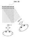
図6に、複数の視線方向から液晶表示画素配列部の全部を遮蔽される例を示す。複数の視線とは、例えば、視線方向Bと視線方向Cである。 図7に、複数の視線方向から液晶表示画素配列部の一部を遮蔽する例を示す。複数の視線とは、例えば、視線方向Bと視線方向Cである。 FIG. 6 shows an example in which the entire liquid crystal display pixel array portion is shielded from a plurality of viewing directions. The plurality of lines of sight are, for example, a line-of-sight direction B and a line-of-sight direction C. FIG. 7 shows an example in which a part of the liquid crystal display pixel array portion is shielded from a plurality of viewing directions. The plurality of lines of sight are, for example, a line-of-sight direction B and a line-of-sight direction C.
(実施形態2の効果) 実施形態2によって、複数の視線方向に対する遮蔽が可能になり、覗き見の視線方向から第三者の予期せぬ視線、たとえば、監視用のカメラの視線や、その他、望遠レンズを用いた覗き見などに対する防御策も同時に取られ、セキュリティーのレベルが上がる、という効果を奏する。 (Effect of Embodiment 2) Embodiment 2 enables shielding with respect to a plurality of line-of-sight directions, and an unexpected line-of-sight of a third party from the line-of-sight line of sight, for example, the line of sight of a monitoring camera, At the same time, defense measures against peeping using a telephoto lens are taken, and the level of security is improved.
≪実施形態3≫ (実施形態3の構成) 実施形態3は、実施形態1または、実施形態2のいずれか一を基本として、特徴点は、実施形態2の視線方向は、液晶表示面に対する略真正面以外からの視線方向であって、略左正面方向、略右正面方向、略上正面方向、略下正面方向、略上右正面方向、略下右正面方向、略下左正面方向、略上左正面方向からなる視線方向群のうち、何れか一又は二以上の組み合わせからなる視線方向である点をあげることができる。 << Embodiment 3 >> (Configuration of Embodiment 3) Embodiment 3 is based on any one of Embodiment 1 or Embodiment 2, and the feature point is that the line-of-sight direction of Embodiment 2 is an abbreviation for the liquid crystal display surface. It is a line-of-sight direction from other than the front, substantially left front direction, substantially right front direction, substantially upper front direction, substantially lower front direction, substantially upper right front direction, substantially lower right front direction, substantially lower left front direction, substantially upper. A point that is a line-of-sight direction composed of any one or a combination of two or more of the line-of-sight direction group consisting of the left front direction can be given.
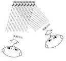
(実施形態3の構成の説明) 実施形態3の、液晶表示画素配列部と、遮蔽液晶部と、に関しては実施形態1または実施形態2と基本的機能は同一であるので、詳細な説明は省略する。「視線方向」は、液晶表示面に対する略真正面以外からの視線方向であって、液晶表示画素配列部を裏側や、真横などから見る視線ではない。略左正面方向と、略右正面方向の視線方向は、たとえば、電車の座席に座った場合に両隣に座った人が液晶表示画素配列部を覗き見する場合の視線方向である。略上正面方向と、略上右正面方向と、略上左正面方向の視線方向は、たとえば、コンピューターを座って操作している場合に、コンピューターを操作する人物の真後ろ、真後ろ右、真後ろに立つ三人が液晶表示画素配列部を覗き見する場合の視線方向である。略下正面方向と、略下右正面方向と、略下左正面方向の視線方向は、たとえば、キャッシュでスペンサーのような水平な液晶表示画素配列部をキャッシュでスペンサーを操作する人物の真後ろ、真後ろ右、真後ろに立つ三人が液晶表示画素配列部を下方から覗き見する場合の視線方向である。 (Description of Configuration of Embodiment 3) Since the basic functions of the liquid crystal display pixel array portion and the shielding liquid crystal portion of Embodiment 3 are the same as those of Embodiment 1 or Embodiment 2, detailed description thereof is omitted. To do. The “line-of-sight direction” is a line-of-sight direction from a position other than substantially in front of the liquid crystal display surface, and is not a line-of-sight viewing the liquid crystal display pixel array portion from the back side or the side. The line-of-sight directions in the substantially left front direction and the substantially right front direction are line-of-sight directions when, for example, people sitting on both sides look into the liquid crystal display pixel array portion when sitting on a train seat. The line-of-sight directions of the substantially upper front direction, the substantially upper right front direction, and the substantially upper left front direction stand, for example, directly behind, right behind, and behind the person operating the computer when sitting and operating the computer. This is the line-of-sight direction when three people look into the liquid crystal display pixel array portion. The line-of-sight directions of the substantially lower front direction, the substantially lower right front direction, and the substantially lower left front direction are, for example, a horizontal liquid crystal display pixel array unit such as a spencer in a cache, directly behind and directly behind a person operating the spencer with a cache. This is the line-of-sight direction when three persons standing right and right behind look at the liquid crystal display pixel array portion from below.
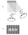
図8(a)には、液晶表示画素配列部に対するそれぞれの視線方向を平面的に表している。また、図8(b)には、液晶表示画素配列部に対するそれぞれの視線を液晶画素配列部を上から見下ろした状態での視線方向を示している。 In FIG. 8A, each line-of-sight direction with respect to the liquid crystal display pixel array portion is shown in a plane. FIG. 8B shows the line of sight with respect to the liquid crystal display pixel arrangement portion in the state where the liquid crystal pixel arrangement portion is looked down from above.
図9には、利用者の視線方向と、遮蔽したい視線方向を液晶表示画素配列部の液晶表示画素レベルで表現している。利用者の視線方向が液晶表示画素配列部の正面からであり、中央の画素が見られるのに対して、それ以外の覗き見をする視線方向A、視線方向B、視線方向C、視線方向D、視線方向Eは、それぞれ、遮蔽液晶部によって形成される遮蔽面によって遮蔽されている。 In FIG. 9, the line-of-sight direction of the user and the line-of-sight direction to be shielded are expressed at the liquid crystal display pixel level of the liquid crystal display pixel array unit. The user's line-of-sight direction is from the front of the liquid crystal display pixel array portion, and the central pixel is seen, while the other lines of sight are the line-of-sight direction A, line-of-sight direction B, line-of-sight direction C, line-of-sight direction D The line-of-sight directions E are each shielded by a shielding surface formed by the shielding liquid crystal unit.
(実施形態3の効果) 実施形態3によって、実施形態1または実施形態2に述べた効果だけでなく、複数の視線方向に対して、それより少ない個数の遮蔽面で視線を遮ったり、複数の視線に対して、異なる部分を遮蔽したり、あるいは逆に見せたりできるように設定することができる、という効果を奏する。 (Effects of Third Embodiment) According to the third embodiment, not only the effects described in the first or second embodiment, but also a plurality of gaze directions can be used to block the line of sight with a smaller number of shielding surfaces, There is an effect that it is possible to set so that different portions can be shielded from the line of sight or can be shown in reverse.
≪実施形態4≫ (実施形態4の構成) 図10を用いて実施形態4を説明する。実施形態4は、実施形態1から3のいずれか一を基本となし、特徴点が、前記遮蔽液晶部により形成される遮蔽面が二層構造である点である。 Embodiment 4 (Configuration of Embodiment 4) Embodiment 4 will be described with reference to FIG. The fourth embodiment is based on any one of the first to third embodiments, and the feature point is that the shielding surface formed by the shielding liquid crystal part has a two-layer structure.
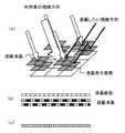
(実施形態4の構成の説明) 実施形態4の液晶表示画素配列部と、遮蔽液晶部と、に関しては実施形態1から実施形態3の何れか一と基本的機能は同一であるので、詳細な説明は省略する。実施形態4の「遮蔽液晶部」は、二層構造である。この二層の間の距離、遮蔽液晶部の電極の幅、厚み、奥行き、さらに、液晶表示画素配列部と遮蔽液晶部の間の距離を最適化することによって、遮蔽される視線方向を任意に設定できる。図10に示すのは、遮蔽液晶部が覗き見である視線方向Bの全部を遮蔽している場合である。一方利用者である視線方向Aについては、遮蔽液晶部によって、一画素ごとに液晶表示画素配列部の液晶表示画素を見ることができる。 (Description of Configuration of Embodiment 4) Since the basic function of the liquid crystal display pixel array portion and the shielding liquid crystal portion of Embodiment 4 is the same as that of any one of Embodiments 1 to 3, the detailed description thereof will be omitted. Description is omitted. The “shielding liquid crystal part” of the fourth embodiment has a two-layer structure. By optimizing the distance between the two layers, the width, thickness, and depth of the electrodes of the shielding liquid crystal unit, and the distance between the liquid crystal display pixel array unit and the shielding liquid crystal unit, the viewing direction to be shielded can be arbitrarily set. Can be set. FIG. 10 shows a case where the shielding liquid crystal unit shields all of the line-of-sight directions B that are peeping. On the other hand, with respect to the viewing direction A, which is the user, the liquid crystal display pixels in the liquid crystal display pixel array section can be seen for each pixel by the shielding liquid crystal section.
図11に示すのは、遮蔽液晶部が覗き見である視線方向Bの部分(中央部のみ)を遮蔽している場合である。利用者である視線方向Aについては、遮蔽液晶部によって、液晶遮蔽部に遮蔽されていない全部と、液晶遮蔽部によって遮蔽されている一画素ごとの液晶表示画素配列部の液晶表示画素を見ることができる。一方、覗き見の視線である視線方向Bは、遮蔽液晶部によって遮蔽されている部分については、その全部が遮蔽され、遮蔽液晶部によって遮蔽されていない部分については、その全部を見ることができる。このように、遮蔽液晶部が一層の場合は、液晶表示画素配列部の画素を非表示にする必要がある場合もあったが、遮蔽液晶部を二層にすることによって、すべての液晶表示画素配列部の画素を表示しながらも、覗き見の視線方向から、液晶表示画素配列部の全部または一部を遮蔽することができる。 FIG. 11 shows a case where the shielding liquid crystal part shields a portion (only the central part) in the line-of-sight direction B that is a peep. As for the user's line-of-sight direction A, see all the liquid crystal display pixels that are not shielded by the liquid crystal shielding part and the liquid crystal display pixel array part for each pixel that is shielded by the liquid crystal shielding part. Can do. On the other hand, in the line-of-sight direction B, which is the line of sight of the peep, all the portions that are shielded by the shielding liquid crystal portion are shielded, and all the portions that are not shielded by the shielding liquid crystal portion can be seen. . As described above, when the shielding liquid crystal portion is a single layer, it may be necessary to hide the pixels of the liquid crystal display pixel array portion. However, by forming the shielding liquid crystal portion into two layers, all the liquid crystal display pixels While displaying the pixels in the array portion, all or part of the liquid crystal display pixel array portion can be shielded from the viewing direction of the peep.
しかし、この二層配列だけで完全に覗き見の視線方向を遮蔽できるわけではない。図12の(a)(b)(c)に示すように、例えば、二層になった遮蔽液晶部において、この二層の間隔を狭くしたり、広くしたりすると、それにともなって遮蔽角が変化する。なお、ここで遮蔽角とは、角度Φであらわされる角度であり、角度Φよりも小さい角度の場合には遮蔽されて液晶画面が見えないということができる。たとえば、角度Φが大きくなるということは、覗き見に必要な角度Φがそれだけ大きくなるために、液晶表示画素配列部の利用者に相当近づかないと覗き見ができなくなる。つまり、覗き見がむずかしくなる。このことから、二層にすることにより、遮蔽の効率は良くなるが、遮蔽できる視線方向は限られた視線の入射角からのものである。 However, this two-layer arrangement alone cannot completely shield the sight line of sight. As shown in FIGS. 12A, 12B, and 12C, for example, in the shielding liquid crystal unit having two layers, when the interval between the two layers is narrowed or widened, the shielding angle is accordingly increased. Change. Here, the shielding angle is an angle represented by an angle Φ, and in the case of an angle smaller than the angle Φ, it can be said that the liquid crystal screen cannot be seen because it is shielded. For example, an increase in the angle Φ means that the angle Φ necessary for peeking increases so that the peeking cannot be performed unless the user of the liquid crystal display pixel array unit is considerably close. In other words, peeking becomes difficult. From this, by using two layers, the shielding efficiency is improved, but the viewing direction that can be shielded is from a limited incident angle of the viewing line.
図13(b)では、実際に斜めから見た場合に液晶表示画素配列部がどのように見えるかのシミュレーション結果を示している。斜めからの視線方向では、液晶表示画素配列部面のほとんどが覆い隠されることが、図13(b)より理解できる。図13(c)では、液晶表示画素配列部から中央部を囲む周辺部のみを遮蔽液晶部で遮蔽した場合を示している。図13(c)では、周囲は遮蔽液晶部で覆われているが、中央部については、斜めからの視線方向でも液晶表示画素配列部が見えることが理解できる。 FIG. 13B shows a simulation result of how the liquid crystal display pixel array portion looks when viewed obliquely. It can be understood from FIG. 13B that most of the liquid crystal display pixel array portion surface is obscured in the oblique viewing direction. FIG. 13C shows a case where only the peripheral portion surrounding the central portion from the liquid crystal display pixel array portion is shielded by the shielding liquid crystal portion. In FIG. 13C, the periphery is covered with the shielding liquid crystal portion, but it can be understood that the liquid crystal display pixel array portion can be seen from the central portion even in the oblique viewing direction.
(実施形態4の効果) 実施形態4によって、液晶表示画素配列部の液晶表示画素を全て表示したまま、覗き見の視線方向については遮蔽が行える、という効果を奏する。 (Effect of Embodiment 4) According to Embodiment 4, there is an effect that the viewing direction of the peeping can be shielded while all the liquid crystal display pixels of the liquid crystal display pixel array unit are displayed.
≪実施形態5≫ (実施形態5の構成) 実施形態5は、実施形態1から3のいずれか一を基本として、特徴点は、前記遮蔽液晶部は、三層以上の構造である点をあげることができる。 << Embodiment 5 >> (Configuration of Embodiment 5) Embodiment 5 is based on any one of Embodiments 1 to 3, and the characteristic point is that the shielding liquid crystal part has a structure of three or more layers. be able to.
(実施形態5の構成の説明) 実施形態5の、液晶表示画素配列部と、遮蔽液晶部と、に関しては実施形態1と基本的機能は同一であるので、詳細な説明は省略する。実施形態5の「遮蔽液晶部」は、三層以上の構造である。遮蔽液晶部は、構造的には、1層単位であるので、これを複数層積み重ねることは技術的に可能である。三層以上の構造にすることによって、より遮蔽角が大きくなる。図14に比較のために、四層の場合と、二層の場合を載せるが、四層にすることによって、遮蔽できる視線方向が増加する、つまり遮蔽角が大きくなることがわかる。したがって、遮蔽という観点からは、三層以上にすることは効果的である。 ただし、実施形態4にあるように、遮蔽角には層の厚みが影響を及ぼすために、三層以上の構造と言えども、層の厚みが二層構造と同じであれば、遮蔽角は同一となる。 (Description of Configuration of Embodiment 5) Since the basic functions of the liquid crystal display pixel array unit and the shielding liquid crystal unit of Embodiment 5 are the same as those of Embodiment 1, detailed description thereof is omitted. The “shielding liquid crystal part” in the fifth embodiment has a structure of three or more layers. Since the shielding liquid crystal portion is structurally one layer unit, it is technically possible to stack a plurality of layers. By making the structure of three or more layers, the shielding angle becomes larger. For comparison, FIG. 14 shows the case of four layers and the case of two layers, but it can be seen that by using four layers, the line-of-sight direction that can be shielded increases, that is, the shielding angle increases. Therefore, it is effective to use three or more layers from the viewpoint of shielding. However, since the thickness of the layer affects the shielding angle as in Embodiment 4, even if the structure has three or more layers, the shielding angle is the same if the layer thickness is the same as the two-layer structure. It becomes.
≪実施形態6≫ (実施形態6の構成) 実施形態6は、実施形態1から実施形態5のいずれか一を基本として、特徴点は、前記遮蔽液晶部は、前記液晶表示画素配列部面に対して略垂直方向に遮蔽面を形成する点である。 << Embodiment 6 >> (Configuration of Embodiment 6) Embodiment 6 is based on any one of Embodiments 1 to 5, characterized in that the shielding liquid crystal section is on the surface of the liquid crystal display pixel array section. In contrast, a shielding surface is formed in a substantially vertical direction.
(実施形態6の構成の説明) 実施形態6の、液晶表示画素配列部と、遮蔽液晶部と、に関しては実施形態1から実施形態5の何れか一と基本的機能は同一であるので、詳細な説明は省略する。実施形態6の「遮蔽液晶部」は、液晶表示画素配列部面に対して略垂直方向に遮蔽面を形成する。略垂直方向とは、図15に示すように、液晶画面に対しておおむね垂直な方向ということである。 (Description of Configuration of Embodiment 6) Since the liquid crystal display pixel arrangement unit and the shielding liquid crystal unit of Embodiment 6 have the same basic function as any one of Embodiments 1 to 5, the details are as follows. The detailed explanation is omitted. The “shielding liquid crystal part” of the sixth embodiment forms a shielding surface in a direction substantially perpendicular to the liquid crystal display pixel array part surface. The substantially vertical direction means a direction substantially perpendicular to the liquid crystal screen as shown in FIG.
これによって効果的に遮蔽をすることが可能となる。しかしながら、さきほどの二層構造や三層構造ほどには、遮蔽角が大きくないことは、図15からわかる。ただし、この遮蔽液晶部の液晶の長さを長くすることによって、遮蔽角を大きくすることが可能になる。長さはおおよそ100ミクロンから500ミクロン程度である。図16は、本実施形態の遮蔽液晶部と液晶表示画素のそれぞれの電極と液晶の部分断面である。遮蔽液晶部は、液晶画面とは異なり、縦型の電極を有する。この縦型の電極の製造は、通常の液晶の作成にくらべてはるかに製作上の困難を伴う。例えば、電極を複数回のフォトリソグラフィープロセスを繰り返すことで高くすることが考えられる。また、真空蒸着やスパッタリングなどの真空膜形成技術を利用せずにメッキを利用して高いアスペクト比を有する電極を形成することができる。また微細でかつ高い壁状の電極を形成する方法として、フォトレジスト膜を電極間の幅に形成しておき、フォトレジスト膜の下地に金属薄膜を配置し、金属薄膜をイオンビームミリングなどの手法により飛散させて前記フォトレジスト膜の側壁に付着させる手法を利用することも可能である。本実施形態によれば、正面から見た場合に、液晶画像を遮蔽する範囲が狭くなるために、それだけ画像を明るくみることができる。実施形態6によれば、遮蔽の目的を果たしつつ、画像を明るく見ることができる、という効果を奏する。 This makes it possible to effectively shield. However, it can be seen from FIG. 15 that the shielding angle is not as large as the two-layer structure or the three-layer structure. However, the shielding angle can be increased by increasing the length of the liquid crystal in the shielding liquid crystal portion. The length is about 100 to 500 microns. FIG. 16 is a partial cross-sectional view of the shielding liquid crystal unit, the electrodes of the liquid crystal display pixel, and the liquid crystal of this embodiment. Unlike the liquid crystal screen, the shielding liquid crystal unit has vertical electrodes. The manufacture of this vertical electrode is far more difficult to manufacture than the production of normal liquid crystals. For example, it is conceivable to raise the electrode by repeating a photolithography process a plurality of times. In addition, an electrode having a high aspect ratio can be formed by using plating without using a vacuum film forming technique such as vacuum deposition or sputtering. In addition, as a method of forming a fine and high wall electrode, a photoresist film is formed in the width between the electrodes, a metal thin film is arranged on the base of the photoresist film, and the metal thin film is subjected to a technique such as ion beam milling. It is also possible to use a method of scattering and adhering to the side wall of the photoresist film. According to this embodiment, since the range which shields a liquid crystal image becomes narrow when it sees from the front, an image can be seen so much that much. According to the sixth embodiment, there is an effect that an image can be viewed brightly while achieving the purpose of shielding.
≪実施形態7≫ (実施形態7の構成) 実施形態7は、実施形態1から5のいずれか一を基本として、特徴点は、前記遮蔽液晶部は、前記液晶表示画素配列部面に対して所定の角度で遮蔽面を形成する点をあげることができる。 << Embodiment 7 >> (Structure of Embodiment 7) Embodiment 7 is based on any one of Embodiments 1 to 5, and the feature point is that the shielding liquid crystal part is in relation to the liquid crystal display pixel array part surface. The point which forms a shielding surface at a predetermined angle can be raised.
(実施形態7の構成の説明) 実施形態7の、液晶表示画素配列部と、遮蔽液晶部と、に関しては実施形態1から実施形態5の何れか一と基本的機能は同一であるので、詳細な説明は省略する。実施形態7の「遮蔽液晶部」は、前記液晶表示画素配列部面に対して所定の角度で遮蔽面を形成する。図17に所定の角度で形成される遮蔽面の概念図を示す。 (Description of Configuration of Embodiment 7) Since the liquid crystal display pixel arrangement unit and the shielding liquid crystal unit of Embodiment 7 have the same basic function as any one of Embodiments 1 to 5, the details are as follows. The detailed explanation is omitted. The “shielding liquid crystal unit” of Embodiment 7 forms a shielding surface at a predetermined angle with respect to the liquid crystal display pixel array unit surface. FIG. 17 shows a conceptual diagram of a shielding surface formed at a predetermined angle.
これによって、特定の視線の方向に対して、優れた遮蔽効果を発揮することができる。また、液晶画面が遮られる範囲が少ないために画面も明るく、欠け落ちる画も少ない、つまり、解像度はあまり落ちない。このために、遮蔽は効果的に行われる一方で、利用者にも劣化しない液晶画像を見ることができるという特徴がある。 Thereby, it is possible to exhibit an excellent shielding effect with respect to a specific line-of-sight direction. In addition, since the range where the liquid crystal screen is blocked is small, the screen is bright and there are few images missing, that is, the resolution does not drop much. For this reason, while shielding is performed effectively, the liquid crystal image which does not deteriorate also for a user can be seen.
図18は、遮蔽液晶部と液晶表示画素配列部の部分断面図である。液晶からなる遮蔽面自身に角度を設定することは困難であるために、例えば、遮蔽液晶部を電極を三層に積み重ね、遮蔽すべき遮蔽液晶部を各層毎に画素をひとつ分ずつずらせる、というものである。このような制御によって、遮蔽液晶部に所定の角度を与えたと同じ効果が得られる。 FIG. 18 is a partial cross-sectional view of the shielding liquid crystal part and the liquid crystal display pixel array part. Since it is difficult to set the angle on the shielding surface itself made of liquid crystal, for example, the shielding liquid crystal part is stacked in three layers, and the shielding liquid crystal part to be shielded is shifted by one pixel for each layer, That's it. By such control, the same effect can be obtained as when a predetermined angle is given to the shielding liquid crystal part.
(実施形態7の効果) 実施形態7の所定の角度で形成する遮蔽面によって、実施形態6の、遮蔽角が小さいという問題を直接的に解決するものである。これによって、遮蔽面がありながらも画面が明るいという特性を有する。しかしながら、実施形態2もしくは実施形態3にて記載された複数の視線の方向に対する遮蔽度についてはかならずしも効果的ではない。 (Effects of Embodiment 7) The shielding surface formed at a predetermined angle in Embodiment 7 directly solves the problem of Embodiment 6 in which the shielding angle is small. As a result, the screen is bright even though there is a shielding surface. However, the degree of shielding with respect to the plurality of line-of-sight directions described in Embodiment 2 or Embodiment 3 is not necessarily effective.
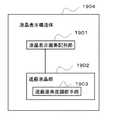
≪実施形態8≫(実施形態8の構成) 図19を用いて、実施形態8を説明する。実施形態8は、実施形態1から実施形態5のいずれか一を基本として、特徴点は、前記遮蔽液晶部1902は、遮蔽面角度調節手段1903をさらに有する点である。 Embodiment 8 (Configuration of Embodiment 8) Embodiment 8 will be described with reference to FIG. The eighth embodiment is based on any one of the first to fifth embodiments, and is characterized in that the shielding
(実施形態8の構成の説明)実施形態8の、液晶表示画素配列部1901と、遮蔽液晶部1902と、に関しては実施形態1と基本的機能は同一であるので、詳細な説明は省略する。実施形態8の「遮蔽液晶部」は、遮蔽面角度調整手段をさらに有する。「遮蔽面角度調整手段」は、前記遮蔽面を形成する角度を変化させる。遮蔽面を形成する角度を変化させるとは、液晶表示画素配列部面に対して垂直な線と、遮蔽面を延長した線が交わってできる交点の角度を変化させるということであり、たとえば、図20中のθの角度を変えるということである。 (Description of Configuration of Embodiment 8) Since the liquid crystal display
図21は、角度調節のための具体的方策を示したものである。例えば、この例では、遮蔽液晶の縦型のものと、横型のものを組み合わせ、縦型の遮蔽液晶の間に横型の遮蔽液晶を配した構造としている。こうすることによって、角度を大きくつける場合に、液晶間にできる隙間を、前記横型の遮蔽液晶により補完し、遮蔽を完全なものにすることができる。実施形態8によって、角度を変化させることによって、覗き見防止、あるいは複数の視線の方向に対する遮蔽、という効果を奏する。 FIG. 21 shows a specific measure for adjusting the angle. For example, in this example, a vertical type and a horizontal type of shielding liquid crystal are combined, and a horizontal type shielding liquid crystal is arranged between the vertical type shielding liquid crystals. In this way, when the angle is increased, the gap formed between the liquid crystals can be complemented by the horizontal shielding liquid crystal, thereby completing the shielding. According to the eighth embodiment, by changing the angle, there is an effect of preventing peeping or shielding against a plurality of gaze directions.
≪実施形態9≫ (実施形態9の構成) 図22を用いて実施形態9を説明する。実施形態9は、実施形態1から8のいずれか一を基本として、特徴点は、前記遮蔽液晶部2203を駆動して前記遮蔽面をスイッチ可能な遮蔽面駆動部2204をさらに有する点をあげることができる。 Embodiment 9 (Configuration of Embodiment 9) Embodiment 9 will be described with reference to FIG. The ninth embodiment is based on any one of the first to eighth embodiments, and the feature point is that it further includes a shielding
(実施形態9の構成の説明) 実施形態9の液晶表示画素配列部2201と、遮蔽液晶部2202と、に関しては実施形態1から実施形態8の何れか一と基本的機能は同一であるので、詳細な説明は省略する。実施形態9の「遮蔽液晶部」は、遮蔽面駆動部をさらに有する。「遮蔽面駆動部」は、前記遮蔽液晶部を駆動して前記遮蔽面をスイッチ可能であることを特徴とする。遮蔽液晶部を駆動し、遮蔽面をスイッチするとは、遮蔽液晶部を駆動させて、遮蔽する視線方向をスイッチするということである。 (Description of Configuration of Ninth Embodiment) Since the liquid crystal display
遮蔽液晶部の駆動による遮蔽面のスイッチによって、複数の視線方向に対する遮蔽面の形成が、実現することができる。また、実施形態8の遮蔽面角度調節手段をあわせて用いれば、スイッチングだけでなく、より効果的な遮蔽も可能になる。実施形態9によって、複数の視線に対する効果的な遮蔽面の構成が簡単にできるようになる、という効果を奏する。また、遮蔽面角度調整手段とあわせ用いれば、遮蔽面のスイッチングだけでなく、遮蔽をより効果的に行える遮蔽面の角度を設定することも可能である。 Formation of a shielding surface for a plurality of line-of-sight directions can be realized by a switch on the shielding surface by driving the shielding liquid crystal unit. Further, when the shielding surface angle adjusting means of the eighth embodiment is used together, not only switching but also more effective shielding is possible. According to the ninth embodiment, there is an effect that it is possible to easily configure an effective shielding surface for a plurality of lines of sight. Further, when used together with the shielding surface angle adjusting means, it is possible to set not only the switching of the shielding surface but also the angle of the shielding surface that can be shielded more effectively.
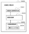
≪実施形態10≫ (実施形態10の構成) 図24を用いて、実施形態10を説明する。 実施形態10は、実施形態1から8のいずれか一を基本として、特徴点は、遮蔽面駆動部2404は、選択スイッチ手段2403を有する点をあげることができる。 << Embodiment 10 >> (Configuration of Embodiment 10) Embodiment 10 will be described with reference to FIG. The tenth embodiment is based on any one of the first to eighth embodiments, and the feature point is that the shielding
(実施形態10の構成の説明) 実施形態10の液晶表示画素配列部2401と、遮蔽液晶部2402と、に関しては実施形態1から実施形態8の何れか一と基本的機能は同一であるので、詳細な説明は省略する。実施形態10の「遮蔽液晶部」は、遮蔽面駆動部をさらに有する。前記「遮蔽面駆動部」は、前記遮蔽液晶部を駆動して前記遮蔽面をスイッチ可能である。 (Description of Configuration of Embodiment 10) Since the liquid crystal display
また、実施形態10の「遮蔽面駆動部」は、選択スイッチ手段を有する。前記「選択スイッチ手段」は、前記視線方向群に含まれる何れか一又は二以上の組合せからなる視線方向を選択的にスイッチ可能である。ここで、「視線方向群」は、実施形態3に述べたように、略左正面方向、略右正面方向、略上正面方向、略下正面方向、略上右正面方向、略下右正面方向、略下左正面方向、略上左正面方向からなる。このような視線方向群のうちのいずれか一または二以上の組み合わせに対して、遮蔽面が形成されるようなスイッチ可能な手段が選択スイッチ手段である。たとえば概念図23に示すように、遮蔽液晶部の遮蔽面が図23(a)のような形で遮蔽面が入っており、左正面もしくは右正面からの複数の視線方向に対する遮蔽面を、上正面もしくは下正面からの複数の視線方向に対する図23(b)のような遮蔽面にスイッチすることである。この例においては、もちろん、図23(b)の遮蔽面を形成した後にこれを駆動して、図23(a)に示される遮蔽面にスイッチさせてもよい。また、上下方向、左右方向が独立にスイッチングされるだけでなく、上下方向に対する遮蔽面および左右方向に対する遮蔽面を同時に形成する図23(c)のような遮蔽面にスイッチさせてもよい。概念図25には、スイッチ可能な遮蔽面の方向について記載している。このようなスイッチ可能な手段によって、複数の視線方向に対して、効果的な遮蔽を行うことができる。効果的な遮蔽が可能であるとは、複数の視線方向に対して、最小限の遮蔽面で前記複数の視線方向を遮蔽するということであるため、液晶画面が暗くならない、解像度が落ちないなどの副次的効果が得られる。実施形態10のスイッチ可能な手段によって、複数の視線方向に対して、効果的な遮蔽を行うことができる。効果的な遮蔽が可能であるとは、複数の視線方向に対して、最小限の遮蔽面で前記複数の視線方向を遮蔽するということであるため、液晶画面が暗くならない、解像度が落ちないなどの副次的効果を奏するものである。 In addition, the “shielding surface driving unit” of the tenth embodiment includes selection switch means. The “selection switch means” can selectively switch the line-of-sight direction composed of any one or two or more combinations included in the line-of-sight direction group. Here, as described in the third embodiment, the “line-of-sight direction group” includes a substantially left front direction, a substantially right front direction, a substantially upper front direction, a substantially lower front direction, a substantially upper right front direction, and a substantially lower right front direction. , Substantially lower left front direction, substantially upper left front direction. A switchable means that forms a shielding surface for any one or a combination of two or more of these line-of-sight direction groups is a selection switch means. For example, as shown in the conceptual diagram 23, the shielding surface of the shielding liquid crystal part has a shielding surface as shown in FIG. 23 (a), and the shielding surface for a plurality of viewing directions from the left front or right front is This is to switch to a shielding surface as shown in FIG. 23B for a plurality of viewing directions from the front or lower front. In this example, of course, after forming the shielding surface of FIG. 23 (b), it may be driven to switch to the shielding surface shown in FIG. 23 (a). Further, not only the vertical direction and the left-right direction are switched independently, but the screen may be switched to a shielding surface as shown in FIG. 23C which simultaneously forms the shielding surface for the vertical direction and the shielding surface for the left-right direction. The conceptual diagram 25 describes the direction of the shielding surface that can be switched. By such switchable means, effective shielding can be performed for a plurality of line-of-sight directions. “Effective shielding is possible” means that the plurality of viewing directions are shielded with a minimum shielding surface with respect to a plurality of viewing directions, so that the liquid crystal screen does not become dark and the resolution does not decrease. The secondary effect of can be obtained. By the switchable means of the tenth embodiment, effective shielding can be performed for a plurality of viewing directions. “Effective shielding is possible” means that the plurality of viewing directions are shielded with a minimum shielding surface with respect to a plurality of viewing directions, so that the liquid crystal screen does not become dark and the resolution does not decrease. It has the secondary effect of.
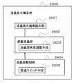
≪実施形態11≫ (実施形態11の構成) 図26を用いて実施形態11を説明する。実施形態11は、実施形態9または10を基本として、特徴点は、前記遮蔽面駆動部は、高速スイッチ手段2604を有する点をあげることができる。 << Embodiment 11 >> (Configuration of Embodiment 11) Embodiment 11 will be described with reference to FIG. The eleventh embodiment is based on the ninth or tenth embodiment, and the feature point is that the shielding surface driving unit has a high-speed switch means 2604.
(実施形態11の構成の説明) 実施形態11の液晶表示画素配列部2601と、遮蔽液晶部2602と、遮蔽面駆動部2604、に関しては実施形態9または10と基本的機能は同一であるので、詳細な説明は省略する。実施形態11の「遮蔽面駆動部」は、「高速スイッチ手段」を有する。 (Description of Configuration of Embodiment 11) Since the liquid crystal display
「高速スイッチ手段」は、一の視線方向から所定の領域の前記液晶表示画素の全部を遮蔽し、かつ、他の視線方向からは、前記遮蔽される領域の前記液晶表示画素の部分的交互の高い周波数での遮蔽と非遮蔽の繰り返しによる前記全部の画素を視認可能とする。 The “fast switch means” shields all of the liquid crystal display pixels in a predetermined region from one line-of-sight direction, and partially alternates the liquid crystal display pixels in the shielded region from the other line-of-sight direction. All the pixels are made visible by repeating shielding and non-shielding at a high frequency.
図27(a)が、ある瞬間の遮蔽液晶部の状態であり、図27(b)が、次の瞬間の遮蔽液晶部の状態である。図27においては、遮蔽液晶部は二層構造になっており、黒い部分が光が遮蔽されるところ、点線の部分が光が透過するところ、である。覗き見される視線方向、すなわち図中の視線方向に対しては、図27(a)の遮蔽液晶部によって、視線は遮蔽される。一方、図27(b)の遮蔽液晶部は、光が透過するところと、遮蔽されるところが、図27(a)の場合と反転する場合であるが、この場合においても、液晶画面の端部においてのみ視線は透過するがそれ以外については、視線は遮蔽される。つまり、遮蔽液晶部の光を遮蔽する液晶の部分が反転しても、常に覗き見の視線方向は遮蔽される。 FIG. 27A shows the state of the shielding liquid crystal unit at a certain moment, and FIG. 27B shows the state of the shielding liquid crystal unit at the next moment. In FIG. 27, the shielding liquid crystal portion has a two-layer structure, where the black portion is where light is shielded and the dotted portion is where light is transmitted. With respect to the line-of-sight direction seen, that is, the line-of-sight direction in the figure, the line-of-sight is shielded by the shielding liquid crystal unit in FIG. On the other hand, the shielding liquid crystal portion in FIG. 27B is a case where the light is transmitted and the portion where the light is shielded is reversed from the case of FIG. The line of sight is transmitted only at, but the line of sight is shielded in other cases. That is, even if the portion of the liquid crystal that shields the light of the shielding liquid crystal portion is inverted, the viewing direction of the peep is always shielded.
本実施形態は、このような特徴を利用して、遮蔽液晶部分を図27(a)、図27(b)のように高速に反転することによって、覗き見の視線方向は遮蔽するが、高速に反転することによって、利用者の目には見えなくなるという効果がある。つまり、利用者にとっては、液晶画面の全部を見ることができるということである。実施形態11によって、遮蔽面を形成するが、明るく解像度も劣化しない画像を提供できるという効果を奏する。 In this embodiment, by utilizing such characteristics, the viewing liquid crystal portion is reversed at a high speed as shown in FIGS. By reversing, it is invisible to the user's eyes. In other words, the user can see the entire liquid crystal screen. According to the eleventh embodiment, the shielding surface is formed, but there is an effect that it is possible to provide an image that is bright and does not deteriorate in resolution.
≪実施形態12≫ (実施形態12の構成) 実施形態12は、実施形態4または5のいずれか一を基本として、特徴点は、遮蔽面駆動部は、前記二層以上の遮蔽液晶部を個別に駆動することにより遮蔽面により遮蔽すべき視線方向を変化させることができる。 << Embodiment 12 >> (Configuration of Embodiment 12) Embodiment 12 is based on any one of Embodiments 4 and 5, and the feature point is that the shielding surface driving unit is configured by individually separating the shielding liquid crystal units of the two or more layers. The direction of the line of sight to be shielded by the shielding surface can be changed by driving to.
(実施形態12の構成の説明) 実施形態12の液晶表示画素配列部と、遮蔽液晶部と、に関しては実施形態4または5の何れか一と基本的機能は同一であるので、詳細な説明は省略する。実施形態12の「遮蔽面駆動部」は、前記二層以上の遮蔽液晶部を個別に駆動することができる。この遮蔽液晶部を個別に駆動して、遮蔽面により遮蔽すべき視線方向を変化させる。 (Description of Configuration of Embodiment 12) Since the liquid crystal display pixel array unit and the shielding liquid crystal unit of Embodiment 12 have the same basic functions as those of any one of Embodiments 4 and 5, detailed description thereof will be given. Omitted. The “shielding surface driving unit” of the twelfth embodiment can individually drive the two or more layers of shielding liquid crystal units. The shielding liquid crystal unit is individually driven to change the line-of-sight direction to be shielded by the shielding surface.
二層以上の遮蔽液晶部を個別に駆動するとは、概念図28に示すように、遮蔽液晶部を液晶画面に平行に移動させる駆動を行うことを言う。平行な方向の駆動によって、遮蔽できる範囲が大きく変わり、実施形態8の図20における遮蔽面角度調整手段と同様な効果が得られる。この層数が増加することにより、さらに、効果的に遮蔽を行うことができる。また、この概念図28では、遮蔽液晶部の一次元的駆動しか表現していないが、さらに、液晶画面に平行な二次元的な面における遮蔽駆動によって、容易に所定の視線方向から液晶表示画素を遮蔽することが可能になる。図29に本実施形態の立体説明図を示す。利用者の斜め方向からの視線方向に対しては、遮蔽液晶はそのいくつかの視線は遮るものの画像を視認することが可能である。このような遮蔽液晶を実現するためには、液晶表示画素よりもさらに小さな画素のものを用いればよい。たとえば、図29(b)には、液晶表示画素の半分のサイズの遮蔽液晶を用いることにより、遮蔽液晶の位置を一層目と二層目で、半画素分づつずらすことが可能になる。図29(c)は、遮蔽液晶の画素を示している。 To individually drive two or more layers of shielding liquid crystal units means to drive the shielding liquid crystal units to move parallel to the liquid crystal screen as shown in the conceptual diagram 28. The range that can be shielded is greatly changed by the driving in the parallel direction, and the same effect as the shielding surface angle adjusting means in FIG. By increasing the number of layers, shielding can be performed more effectively. Further, in this conceptual diagram 28, only one-dimensional driving of the shielding liquid crystal unit is expressed, but further, liquid crystal display pixels can be easily viewed from a predetermined viewing direction by shielding driving in a two-dimensional plane parallel to the liquid crystal screen. Can be shielded. FIG. 29 shows a three-dimensional explanatory diagram of this embodiment. With respect to the line-of-sight direction from the oblique direction of the user, the shielding liquid crystal can visually recognize an image although some of the lines of sight are blocked. In order to realize such a shielding liquid crystal, a pixel smaller than the liquid crystal display pixel may be used. For example, in FIG. 29B, by using a shielding liquid crystal that is half the size of the liquid crystal display pixel, the position of the shielding liquid crystal can be shifted by half a pixel between the first layer and the second layer. FIG. 29C shows a pixel of the shielding liquid crystal.
また、図30には、遮蔽液晶の位置をずらせることによって、見え方がどのように変わるかをシミュレートしている。図30(a)は、遮蔽液晶部の同じ位置を遮蔽した場合であり、液晶画面全部にわたって斜めからの視線方向が遮られるために、液晶画面が見づらくなっている。しかし、図30(b)のように斜めからの視線方向に対して、一層目と二層目の遮蔽液晶部が重なるようにすると、液晶画面は、かなり見えるようになる。 Further, FIG. 30 simulates how the appearance changes by shifting the position of the shielding liquid crystal. FIG. 30A shows a case where the same position of the shielding liquid crystal unit is shielded, and the liquid crystal screen is difficult to see because the viewing direction from an oblique direction is blocked over the entire liquid crystal screen. However, as shown in FIG. 30B, when the first and second shielding liquid crystal portions overlap each other with respect to the oblique viewing direction, the liquid crystal screen becomes considerably visible.
さらに、図30(c)と(d)のシミュレーション結果によれば、遮蔽液晶部のずらせ方によって、さまざまな遮蔽面の形成の可能性があることがわかる。実施形態12によって、二層のものを駆動することによって、効果的に遮蔽面を形成することができる、という効果を奏する。 Further, according to the simulation results of FIGS. 30C and 30D, it can be seen that various shielding surfaces may be formed depending on how the shielding liquid crystal portion is displaced. According to the twelfth embodiment, it is possible to effectively form a shielding surface by driving two layers.
≪実施形態13≫ (実施形態13の構成) 図31を用いて実施形態13を説明する。実施形態13は、実施形態1から実施形態12のいずれか一を基本として、特徴点は、遮蔽液晶部は、前記液晶表示画素の一部を所定の視線方向から遮蔽することにより文字、図形、記号を表すことが可能である点をあげることができる。 << Embodiment 13 >> (Configuration of Embodiment 13) Embodiment 13 will be described with reference to FIG. The thirteenth embodiment is based on any one of the first to twelfth embodiments, and the feature point is that the shielding liquid crystal unit shields a part of the liquid crystal display pixel from a predetermined line-of-sight direction to thereby make a character, figure, The points that can represent symbols can be mentioned.
(実施形態13の構成の説明) 実施形態13の、液晶表示画素配列部と、遮蔽液晶部と、に関しては実施形態1から実施形態12の何れか一と基本的機能は同一であるので、詳細な説明は省略する。実施形態13の「遮蔽液晶部」は、前記液晶表示画素の一部を所定の視線方向から遮蔽することにより文字、図形、記号を表す。すなわち、遮蔽液晶もまた液晶であるという特徴を利用して、この遮蔽液晶部を文字、図形、記号を表す用途に用いる、ということである。 (Description of Configuration of Embodiment 13) The basic function of the liquid crystal display pixel array unit and the shielding liquid crystal unit of Embodiment 13 is the same as that of any one of Embodiments 1 to 12, and therefore the details thereof are described. The detailed explanation is omitted. The “shielding liquid crystal unit” of the thirteenth embodiment represents characters, figures, and symbols by shielding a part of the liquid crystal display pixels from a predetermined viewing direction. In other words, using the characteristic that the shielding liquid crystal is also a liquid crystal, this shielding liquid crystal portion is used for applications representing characters, figures, and symbols.
たとえば、図31に示すように、利用者が見る液晶表示画素と、覗き見をする液晶表示画素が異なる場合に、覗き見する側に見える液晶表示画素からなる液晶画面には、上記の文字、図形、記号を表すことにより、本実施形態を達成してもよい。実施形態13では、遮蔽液晶もまた液晶であるという特徴を利用して、この遮蔽液晶部を文字、図形、記号を表す用途に用いる、という効果を奏する。 For example, as shown in FIG. 31, when a liquid crystal display pixel viewed by a user is different from a liquid crystal display pixel to be peeped, a liquid crystal screen composed of a liquid crystal display pixel that is visible on the side to be peeped has the above characters, This embodiment may be achieved by representing figures and symbols. In the thirteenth embodiment, using the characteristic that the shielding liquid crystal is also a liquid crystal, there is an effect that the shielding liquid crystal portion is used for the purpose of representing characters, figures, and symbols.
≪実施形態14≫ (実施形態14の構成) 図32を用いて実施形態14を説明する。実施形態14は、実施形態1から13のいずれか一を基本とした液晶表示構造体を含む電子機器に関する。 << Embodiment 14 >> (Configuration of Embodiment 14) Embodiment 14 will be described with reference to FIG. The fourteenth embodiment relates to an electronic device including a liquid crystal display structure based on any one of the first to thirteenth embodiments.
(実施形態14の構成の説明) 実施形態14の液晶表示構造体は、実施形態1から13の何れか一に記載したものと基本的機能は同一であるので詳細な説明は省略する。 (Description of Configuration of Embodiment 14) Since the liquid crystal display structure of Embodiment 14 has the same basic function as that described in any one of Embodiments 1 to 13, detailed description thereof will be omitted.
実施形態14は、実施形態1から13のいずれか一に記載の液晶表示構造体を含む電子機器である。たとえば、携帯電話、コンピューター、テレビ、カーナビゲーションシステム、Lモードの画面、キャッシュディスペンサーその他液晶がモニターとして用いられるすべての電子機器を含む。実施形態14の実施形態1から13のいずれか一の液晶表示構造体が用いられることによって、電子機器のセキュリティーレベルが向上する、プライバシーを守ることができる、個人情報が盗まれにくくなる、認証情報などが盗まれにくくなる、などの効果を奏する。 Embodiment 14 is an electronic device including the liquid crystal display structure according to any one of Embodiments 1 to 13. For example, a mobile phone, a computer, a television, a car navigation system, an L-mode screen, a cash dispenser, and all other electronic devices in which a liquid crystal is used as a monitor are included. Use of the liquid crystal display structure according to any one of the first to thirteenth embodiments of the fourteenth embodiment improves the security level of the electronic device, protects privacy, and makes it difficult for personal information to be stolen. The effect is that it is difficult to be stolen.
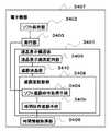
≪実施形態15≫ (実施形態15の構成) 図33を用いて実施形態15を説明する。実施形態15は、実施形態14を基本として、特徴点は、ソフト保持部0802と、実行部0803と、ソフト遮蔽命令取得手段0805を有する点をあげることができる。 Embodiment 15 Configuration of Embodiment 15 Embodiment 15 will be described with reference to FIG. In the fifteenth embodiment, on the basis of the fourteenth embodiment, the feature points may include a software holding unit 0802, an execution unit 0803, and a soft shielding instruction acquisition unit 0805.
(実施形態15の構成の説明) 実施形態15の、液晶表示構造体0801は、実施形態14の基本的機能と同一であるので詳細な説明は省略する。「ソフト保持部」は、ソフトを保持する。この保持されるソフトは、遮蔽面を制御することに関わるソフトウエアである。「実行部」は、ソフト保持部に保持されているソフトウエアを実行する。 実施形態15の「遮蔽面駆動部」は、遮蔽命令取得手段を有する。 「遮蔽命令取得手段」は、ソフト遮蔽命令を取得する。 (Description of Configuration of Embodiment 15) Since the liquid crystal display structure 0801 of Embodiment 15 has the same basic function as that of Embodiment 14, detailed description thereof is omitted. The “software holding unit” holds software. This held software is software related to controlling the shielding surface. The “execution unit” executes software held in the software holding unit. The “shielding surface driving unit” of the fifteenth embodiment includes shielding command acquisition means. The “shielding command acquisition unit” acquires a soft shielding command.
「ソフト遮蔽命令」は、前記実行部で実行されるソフトウエアから前記遮蔽面を遮蔽するための命令である。ソフト遮断命令によって、ソフトウェアから遮蔽面を制御することによって、遮断面を自由に制御することが可能になる。すなわち、遮蔽液晶部のプログラムによる遮蔽制御が可能になる。実施形態15によって、遮蔽液晶部のプログラムによる遮蔽制御が可能になるために、アプリケーションに応じた遮蔽制御が可能となる。例えば、お互いに相手が見ている画面を遮蔽された状態で二人が一つの画面を見ながら、相手が何を見ているか当てるゲームソフトなどに応用できる。また、セキュリティの高いパスワード入力画面などが表示される際にのみ他の真正面以外の他の視線方向を遮蔽面で遮蔽することなどが可能である。 The “soft shielding instruction” is an instruction for shielding the shielding surface from software executed by the execution unit. By controlling the shielding surface from the software by the soft interruption command, the interruption surface can be freely controlled. That is, the shielding control by the program of the shielding liquid crystal unit becomes possible. According to the fifteenth embodiment, since the shielding control by the program of the shielding liquid crystal unit is possible, the shielding control according to the application is possible. For example, the present invention can be applied to game software in which two people look at one screen while the screens viewed by each other are shielded, and hit what the other party is looking at. In addition, it is possible to shield other line-of-sight directions other than right in front with a shielding surface only when a password input screen with high security is displayed.
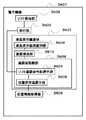
≪実施形態16≫ (実施形態16の構成) 図34を用いて実施形態16を説明する。実施形態16は、実施形態14または15のいずれか一を基本として、特徴点は、時間情報取得部0906と、時間依存遮蔽手段0905をさらに有する点をあげることができる。 << Embodiment 16 >> (Configuration of Embodiment 16) Embodiment 16 will be described with reference to FIG. In the sixteenth embodiment, on the basis of any one of the fourteenth and fifteenth embodiments, the feature points may include a point further including a time information acquisition unit 0906 and a time-dependent shielding unit 0905.
(実施形態16の構成の説明) 実施形態16の、液晶表示構造体と、ソフト保持部0902と、実行部0903と、ソフト遮蔽命令取得手段0904と、に関しては基本的機能は実施形態14または実施形態15と同一であるために詳細な説明は省略する。 (Description of Configuration of Sixteenth Embodiment) The basic functions of the liquid crystal display structure, the software holding unit 0902, the execution unit 0903, and the soft shielding command acquisition unit 0904 according to the sixteenth embodiment are the same as those in the fourteenth embodiment. Since it is the same as Embodiment 15, detailed description is omitted.
「時間情報取得部」は、時間を示す情報である時間情報を取得する。「時間情報」とは、時刻の場合と、時刻でない時間の場合、年月日、曜日、六曜などがある。実施形態16の「遮断面駆動部」は、「時間依存遮蔽手段」をさらに有する。「時間依存遮蔽手段」は、前記時間情報取得部が取得した時間情報に基づいて前記遮蔽面を遮蔽する。実施形態16によって、指定した曜日や、指定した年月日、毎日の指定した時刻などに、遮蔽面を作動させるなどの制御が可能になる。たとえば、通勤の車中にてPDAを用いて、英会話の勉強を行う場合に、通勤の時間が午前8時から午前9時である場合、毎日のその時間帯において覗き見防止のための液晶画面の遮蔽を行うことが本実施形態により可能となる。実施形態16によって、指定した曜日や、指定した年月日、毎日の指定した時刻などに、遮蔽面を作動させるなどの制御が可能になるなどの効果を奏する。 The “time information acquisition unit” acquires time information that is information indicating time. The “time information” includes a date, a day of the week, a day of the week, and a sixth day in the case of a time and a time that is not a time. The “blocking surface driving unit” of the sixteenth embodiment further includes “time-dependent shielding means”. The “time-dependent shielding unit” shields the shielding surface based on the time information acquired by the time information acquisition unit. According to the sixteenth embodiment, it is possible to perform control such as operating the shielding surface on a specified day of the week, a specified date, a specified time every day, or the like. For example, when studying English conversation using a PDA in a commuting car, if the commuting time is from 8:00 am to 9:00 am, a liquid crystal screen to prevent peeping at that time every day According to this embodiment, it is possible to perform shielding. According to the sixteenth embodiment, there is an effect that it is possible to perform control such as operating the shielding surface on a specified day of the week, a specified date, a specified time every day, or the like.
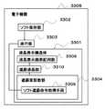
≪実施形態17≫ (実施形態17の構成) 図35を用いて、実施形態17を説明する。実施形態17は、実施形態14から16のいずれか一を基本として、特徴点は、位置情報取得部1006を有し、前記遮蔽面駆動部1008は位置依存遮蔽手段1005をさらに有する点をあげることができる。 << Embodiment 17 >> (Configuration of Embodiment 17) Embodiment 17 will be described with reference to FIG. In the seventeenth embodiment, based on any one of the fourteenth to sixteenth embodiments, the feature point includes a position information acquisition unit 1006, and the shielding surface driving unit 1008 further includes a position-dependent shielding unit 1005. Can do.
(実施形態17の構成の説明) 実施形態17の液晶表示構造体1001と、ソフト保持部1002と、実行部1003と、ソフト遮蔽命令取得手段1004と、に関しては基本的機能は実施形態14から実施形態16の何れか一と同一であるために詳細な説明は省略する。「位置情報取得部」は、位置を示す情報である位置情報を取得する。「遮蔽面駆動部」は、位置依存遮蔽手段をさらに有する。「位置依存遮断手段」は、前記位置情報取得部が取得した位置情報に基づいて前記遮蔽面を遮蔽する。この情報と、実施形態15のソフトウエア遮断命令取得手段および実施形態16の時間依存遮蔽手段をあわせ用いれば、指定した時間に指定した位置に遮蔽面を自動的に形成することが可能になる。 (Description of Configuration of Embodiment 17) With respect to the liquid crystal display structure 1001, the software holding unit 1002, the execution unit 1003, and the soft shielding command acquisition unit 1004 of Embodiment 17, basic functions are implemented from the 14th embodiment. Since it is the same as any one of form 16, detailed description is abbreviate | omitted. The “position information acquisition unit” acquires position information that is information indicating a position. The “shielding surface driving unit” further includes position-dependent shielding means. The “position-dependent blocking means” blocks the shielding surface based on the position information acquired by the position information acquisition unit. If this information is used together with the software interruption command acquisition means of the fifteenth embodiment and the time-dependent shielding means of the sixteenth embodiment, it is possible to automatically form a shielding surface at a designated position at a designated time.
たとえば、実施形態16の例を用いて説明する。通勤の車中にてPDAを用いて、英会話の勉強を行う場合に、通勤の時間が午前8時から午前9時である場合、毎日のその時間帯において覗き見防止のための液晶画面の遮蔽が可能となる。ここで、液晶画面を遮蔽する時間帯を指定すると同時に、遮蔽するべき視線方向の位置情報を指定する。たとえば、通勤電車の座席に座ってPDAを用いて英会話の勉強をしていることを想定して、つり革につかまる人の視線方向つまり上正面の視線方向と、左どなりに座る人の視線方向つまり左正面の視線方向と、および右どなりに座る人の視線方向つまり右正面の視線方向と、の三つの視線方向を、午前8時から午前9時の間の通勤時間の一時間の間だけ毎日定期的に遮蔽することが本実施形態を通じて可能になる。 For example, a description will be given using an example of the sixteenth embodiment. When studying English conversation using a PDA in a commuting car, if the commuting time is from 8:00 am to 9:00 am, the LCD screen is shielded to prevent peeping at that time every day. Is possible. Here, the time zone for shielding the liquid crystal screen is designated, and at the same time, the position information in the sight line direction to be shielded is designated. For example, assuming that you are sitting on a commuter train seat and studying English conversation using a PDA, the direction of the line of sight of the person holding the strap, that is, the line of sight of the upper front, and the line of sight of the person sitting on the left In other words, the three gaze directions, the left gaze direction and the right gaze direction of the person sitting on the right side, that is, the right front gaze direction, are regularly scheduled for one hour of commuting time between 8 am and 9 am Through this embodiment, it is possible to shield it.
(実施形態17の効果) 実施形態17を用いれば、取得した位置情報にもとづいて遮蔽面を形成することが可能となり、さらに、実施形態16と実施形態17の技術とあわせ用いれば、指定した時間に指定した位置に遮蔽面を自動的に形成することが可能となる、という効果を奏する。 (Effect of Embodiment 17) If Embodiment 17 is used, it becomes possible to form a shielding surface based on the acquired position information. Furthermore, if it is used in combination with the techniques of Embodiments 16 and 17, a specified time is used. It is possible to automatically form a shielding surface at a position specified in (1).
≪実施形態18≫ (実施形態18の構成) 図36を用いて、実施形態18を説明する。 実施形態18は、実施形態14から実施形態17のいずれか一を基本として、特徴点は、通信部1106を有し、前記遮蔽面駆動部1108は遮蔽面駆動命令取得手段1104を有する点をあげることができる。 Embodiment 18 Configuration of Embodiment 18 Embodiment 18 will be described with reference to FIG. The eighteenth embodiment is based on any one of the fourteenth to seventeenth embodiments, and the feature point is that it has a communication unit 1106, and the shielding surface driving unit 1108 has a shielding surface driving command acquisition means 1104. be able to.
(実施形態18の構成の説明) 実施形態18の液晶表示構造体1101と、ソフト保持部1102と、実行部1103と、に関しては基本的機能は実施形態16と同一であるために詳細な説明は省略する。「通信部」は、通信するための機能を有し、主として遮蔽面を駆動するための命令を通信する。実施形態18の「遮蔽面駆動部」は、遮蔽面駆動命令取得手段を有する。「遮蔽面駆動命令取得手段」は、遮蔽面駆動命令を取得する。 (Description of Configuration of Embodiment 18) Since the basic functions of the liquid crystal display structure 1101, the software holding unit 1102, and the execution unit 1103 of Embodiment 18 are the same as those of Embodiment 16, detailed description thereof will be omitted. Omitted. The “communication unit” has a function for communicating, and mainly communicates a command for driving the shielding surface. The “shielding surface driving unit” according to the eighteenth embodiment includes shielding surface driving command acquisition means. The “shielding surface driving command acquisition unit” acquires a shielding surface driving command.
「遮蔽面駆動命令」とは、前記通信部を介して前記遮蔽面を駆動するための命令である。遮蔽面を駆動するための命令とは、時間情報または位置情報に関する命令である。また、それ以外の遮蔽液晶部の遮蔽面の形成方法に関する命令も含まれる。 The “shielding surface driving command” is a command for driving the shielding surface via the communication unit. The command for driving the shielding surface is a command related to time information or position information. Moreover, the command regarding the formation method of the shielding surface of the other shielding liquid crystal part is also contained.
上記手段によれば、通信部から遮蔽面駆動に関する命令を取得し、これに従って遮蔽面を形成するというものであり、一例をあげれば、コンピューター端末上にて、まず、以下のような設定を行う。すなわち、遮蔽面を形成する時間を午前8時から午前9時の間に設定し、遮蔽面を形成する位置を上正面、左正面、右正面の三つ視線方向に設定し、さらに、これを自動的に毎日定期的に同時刻に遮蔽面を形成する、などの設定を行う。そして、これらの設定情報をコンピューターからPDAに対して遮蔽面駆動命令として送信する。この命令を受けたPDAの通信部は、この設定情報を受信し、さらに前記遮断面駆動命令を取得し、この遮断面駆動命令に従って遮断面駆動部を駆動させる。なお、上記コンピューター端末は、携帯あるいは、PDAであってもよく、遮蔽面駆動命令を送受信できるものであれば、なんでもよい。 According to the above means, a command for driving the shielding surface is acquired from the communication unit, and the shielding surface is formed accordingly. For example, on the computer terminal, first, the following setting is performed. . That is, the time for forming the shielding surface is set between 8:00 am and 9:00 am, and the position for forming the shielding surface is set in the three viewing directions of the upper front, the left front, and the right front. For example, a shield surface is formed at the same time every day. Then, the setting information is transmitted from the computer to the PDA as a shielding surface driving command. The communication unit of the PDA that has received this command receives the setting information, acquires the blocking surface driving command, and drives the blocking surface driving unit in accordance with the blocking surface driving command. The computer terminal may be a portable or PDA, and may be anything as long as it can transmit and receive a shielding surface driving command.
また、別の具体例では、電子機器間での通信による遮蔽がある。すなわち、電子機器をもった人物が背後に近づいてきたときに、通信部が自動的にその接近と接近の方向を感知し、その人物の視線方向に対して遮蔽面を自動的に形成する場合である。
実施形態18によって、通信を介して遮蔽面の形成に関する情報を送受信することが可能になり、液晶表示構造体を有する電子機器を他の機器から制御するための情報を受信したり、さらには、他の機器から直接制御したりすることができる、という効果を奏する。In another specific example, there is shielding by communication between electronic devices. In other words, when a person with an electronic device approaches the back, the communication unit automatically senses the approaching and approaching direction and automatically forms a shielding surface for the person's line of sight It is.
According to the eighteenth embodiment, it becomes possible to transmit and receive information regarding the formation of the shielding surface via communication, and to receive information for controlling the electronic device having the liquid crystal display structure from another device, There is an effect that it can be directly controlled from other devices.
≪実施形態19≫ (実施形態19の構成) 図37を用いて実施形態19を説明する。実施形態19は、実施形態14から18のいずれか一を基本として、特徴点は、液晶画面位置関係情報取得部を有し、前記遮蔽面駆動部1208は、液晶画面位置関係情報依存遮蔽手段1205をさらに有する。 Embodiment 19 (Configuration of Embodiment 19) Embodiment 19 will be described with reference to FIG. The nineteenth embodiment is based on any one of the fourteenth to eighteenth embodiments, and the feature point includes a liquid crystal screen positional relationship information acquisition unit, and the shielding surface driving unit 1208 includes a liquid crystal screen positional relationship information-dependent shielding unit 1205. It has further.
(実施形態19の構成の説明) 実施形態19の液晶表示構造体1201と、ソフト保持部1202と、実行部1203と、ソフト遮蔽命令取得手段1204と、に関しては基本的機能は実施形態14から実施形態18の何れか一と同一であるために詳細な説明は省略する。「液晶画面位置関係情報取得部」は、液晶画面位置関係情報を取得する。「液晶画面位置関係情報」とは、前記液晶表示画素配列部により構成される液晶画面の利用者にとっての上下・左右を示す位置関係を示す情報である。この利用者にとっての上下・左右を示す位置関係を示す情報をもとに、上正面、右正面、左正面などの視線方向を決定づけることができる。たとえば表示の切り替えが可能な液晶画面を有するような携帯端末の場合、視線方向を定めるための基本となる上下・左右が液晶画面のいずれに相当するかを決定づけることによって、正しい遮蔽面を形成することが可能になる。 (Description of Configuration of Nineteenth Embodiment) With respect to the liquid crystal display structure 1201, the software holding unit 1202, the execution unit 1203, and the soft shielding command acquisition unit 1204 of the nineteenth embodiment, basic functions are implemented from the fourteenth embodiment. Since it is the same as any one of the forms 18, detailed description is abbreviate | omitted. The “liquid crystal screen positional relationship information acquisition unit” acquires liquid crystal screen positional relationship information. “Liquid crystal screen positional relationship information” is information indicating the positional relationship indicating the vertical and horizontal directions for the user of the liquid crystal screen configured by the liquid crystal display pixel array unit. Based on the information indicating the positional relationship indicating the top / bottom / left / right for the user, the line-of-sight directions such as the top front, the right front, and the left front can be determined. For example, in the case of a portable terminal having a liquid crystal screen capable of switching display, a correct shielding surface is formed by determining which one of the liquid crystal screens corresponds to the top, bottom, left and right, which is the basis for determining the viewing direction. It becomes possible.
また、この上下左右を判断する方法としては、たとえば、液晶表示構造体を含む電子機器の液晶画面の後ろ側に、重力によって常に下方向を指し示す錘を内蔵させて、この錘の指し示す方向を「下」、その反対方向を「上」となし、錘から見て液晶画面の「向かって右」を利用者からみた「左」となし、錘から見て液晶画面の「向かって左」を利用者から見た「右」となす、ことによって方向を決定することができる。 In addition, as a method of determining the top, bottom, left, and right, for example, a weight that always points downward by gravity is built in the back side of the liquid crystal screen of the electronic device including the liquid crystal display structure, and the direction indicated by this weight is indicated by “ “Down”, the opposite direction is “Up”, and “Right” of the LCD screen as viewed from the weight is “Left” as viewed from the user, “Left” of the LCD screen is viewed from the weight The direction can be determined by assuming “right” as viewed from the person.
実施形態19の「遮蔽面駆動部」は、液晶画面位置関係情報依存遮蔽手段をさらに有する。「液晶画面位置関係情報依存手段」は、前記液晶画面位置関係情報取得部が取得した液晶画面位置関係情報に基づいて前記遮蔽面を遮蔽する。前記液晶画面位置関係情報に基づいて、遮蔽面駆動部を正しく駆動させることが可能になる。 The “shielding surface driving unit” according to the nineteenth embodiment further includes liquid crystal screen positional relationship information-dependent shielding means. The “liquid crystal screen positional relationship information dependent unit” shields the shielding surface based on the liquid crystal screen positional relationship information acquired by the liquid crystal screen positional relationship information acquisition unit. Based on the liquid crystal screen positional relationship information, the shielding surface driving unit can be driven correctly.
実施形態3においては、略左正面方向、略右正面方向、略上正面方向、略下正面方向、略上右正面方向、略下右正面方向、略下左正面方向、略上左正面方向からなる視線方向群が定義され、これらのいずれか一または二以上の組み合わせからなる視線方向に対して遮蔽面が形成されるが、本実施形態19によって、この視線方向が液晶画面のどの方向に対応し、ひいては、どの位置に遮蔽面を形成すべきかの指標となる情報が提供される。 In the third embodiment, from a substantially left front direction, a substantially right front direction, a substantially upper front direction, a substantially lower front direction, a substantially upper right front direction, a substantially lower right front direction, a substantially lower left front direction, and a substantially upper left front direction. The line-of-sight direction group is defined, and a shielding surface is formed for the line-of-sight direction composed of any one or a combination of these. According to the nineteenth embodiment, the line-of-sight direction corresponds to which direction of the liquid crystal screen. As a result, information serving as an index of where the shielding surface should be formed is provided.
(実施形態19の効果) 本実施形態19によって、実施形態3における視線方向が液晶画面のどの方向に対応し、ひいては、どの位置に遮蔽面を形成すべきかの指標となる情報が提供される、という効果を奏する。 (Effect of Nineteenth Embodiment) According to the nineteenth embodiment, information serving as an indicator of which direction of the liquid crystal screen corresponds to the line-of-sight direction in the third embodiment and thus where the shielding surface should be formed is provided. There is an effect.
≪実施形態20≫ (実施形態20の構成) 実施形態20の構成は、実施形態19を基本とする。特徴点は、前記液晶画面位置関係情報依存遮蔽手段は、常に視線方向として液晶画面の略左正面方向となる視線方向及び略右正面方向となる視線方向から前記液晶表示画素配列部上に配置される前記液晶表示画素の全部又は、一部を遮蔽する点をあげることができる。 Embodiment 20 Configuration of Embodiment 20 The configuration of Embodiment 20 is based on Embodiment 19. The characteristic point is that the liquid crystal screen positional relationship information-dependent shielding means is always arranged on the liquid crystal display pixel array unit from the line-of-sight direction as the substantially left front direction and the line-of-sight direction as the right front direction as the line-of-sight direction. The point which shields all or one part of the said liquid crystal display pixel can be mention | raise | lifted.
(実施形態20の構成の説明) 実施形態20の液晶表示構造体と、ソフト保持部と、実行部と、ソフト遮蔽命令取得手段と、に関しては基本的機能は実施形態19と同一であるために詳細な説明は省略する。 (Description of Configuration of Embodiment 20) The basic functions of the liquid crystal display structure, the software holding unit, the execution unit, and the soft shielding command acquisition unit of Embodiment 20 are the same as those of Embodiment 19 Detailed description is omitted.
実施形態20の「液晶画面位置関係情報依存遮蔽手段」は、常に視線方向として液晶画面の略左正面方向となる視線方向及び略右正面方向となる視線方向から前記液晶表示画素配列部上に配置される前記液晶表示画素の全部又は、一部を遮蔽する。すなわち、デフォルトとして、液晶画面の略左正面の視線方向に対する遮蔽面と、液晶画面の略右正面の視線方向に対する遮蔽面と、に関しては自動的にこれらの遮蔽面が形成されるようにあらかじめ設定されている、ということを示している。さらに、その遮蔽面については、液晶表示画素のうち全部又は、一部を遮蔽することがデフォルトとして設定されていることを示している。 The “liquid crystal screen positional relationship information-dependent shielding means” according to the twentieth embodiment is always arranged on the liquid crystal display pixel array unit from the line-of-sight direction as the substantially left front direction and the line-of-sight direction as the right front direction as the line-of-sight direction. All or a part of the liquid crystal display pixels are shielded. That is, as a default, the shielding surface for the line-of-sight direction of the substantially left front of the liquid crystal screen and the shielding surface for the line-of-sight direction of the substantially right front of the liquid crystal screen are set in advance so that these shielding surfaces are automatically formed. It has been shown that. Further, regarding the shielding surface, it is shown that shielding all or a part of the liquid crystal display pixels is set as a default.
実施形態19において、液晶画面の利用者にとっての上下・左右を示す位置関係を示す情報が取得されるが、この情報に基づいて本実施形態の遮蔽面が形成されるために、常に、略左正面および略右正面の視線方向に対して遮蔽面が形成されることが保証される。 In the nineteenth embodiment, information indicating the positional relationship indicating the up / down / left / right directions for the user of the liquid crystal screen is acquired. Since the shielding surface of the present embodiment is formed based on this information, the information is always substantially left. It is guaranteed that a shielding surface is formed with respect to the front and substantially right frontal viewing directions.
(実施形態20の効果) 実施形態20によって、デフォルト値として略左正面および略右正面の視線方向に対して遮蔽面が形成される、という効果を奏する。さらに、実施形態19との相乗効果により、液晶画面の方向にかかわらず、常に、前記視線方向に対する遮蔽面の形成が保証される。 (Effect of Embodiment 20) According to Embodiment 20, there is an effect that a shielding surface is formed with respect to the line-of-sight directions of the substantially left front and the substantially right front as default values. Further, the synergistic effect with the nineteenth embodiment always ensures the formation of the shielding surface in the line-of-sight direction regardless of the direction of the liquid crystal screen.
≪実施形態21≫ (実施形態21の構成) 実施形態21の構成は、実施形態19を基本とする。特徴点は、前記液晶画面位置関係情報依存遮蔽手段は、常に視線方向として液晶画面の略上正面方向となる視線方向及び略下正面方向となる視線方向から前記液晶表示画素配列部上に配置される前記液晶表示画素の全部又は、一部を遮蔽する点をあげることができる。 << Embodiment 21 >> (Configuration of Embodiment 21) The configuration of Embodiment 21 is based on Embodiment 19. The characteristic point is that the liquid crystal screen positional relationship information-dependent shielding means is always arranged on the liquid crystal display pixel array section from the line-of-sight direction which is the substantially upper front direction of the liquid crystal screen and the line-of-sight direction which is the substantially lower front direction. The point which shields all or one part of the said liquid crystal display pixel can be mention | raise | lifted.
(実施形態21の構成の説明) 実施形態21の液晶表示構造体と、ソフト保持部と、実行部と、ソフト遮蔽命令取得手段と、に関しては基本的機能は実施形態19と同一であるために詳細な説明は省略する。 (Description of Configuration of Embodiment 21) Since the liquid crystal display structure, the software holding unit, the execution unit, and the soft shielding command acquisition unit of Embodiment 21 have the same basic functions as those of Embodiment 19, Detailed description is omitted.
実施形態21の「液晶画面位置関係情報依存遮蔽手段」は、常に視線方向として液晶画面の略上正面方向となる視線方向及び略下正面方向となる視線方向から前記液晶表示画素配列部上に配置される前記液晶表示画素の全部又は、一部を遮蔽する。すなわち、デフォルトとして、液晶画面の略上正面の視線方向に対する遮蔽面と、液晶画面の略下正面の視線方向に対する遮蔽面と、に関しては自動的にこれらの遮蔽面が形成されるようにあらかじめ設定されている、ということを示している。さらに、その遮蔽面については、液晶表示画素のうち全部又は、一部を遮蔽することがデフォルトとして設定されていることを示している。 The “liquid crystal screen positional relationship information-dependent shielding means” according to the twenty-first embodiment is always arranged on the liquid crystal display pixel array unit from the line-of-sight direction that is the substantially upper front direction of the liquid crystal screen and the line-of-sight direction that is the substantially lower front direction. All or a part of the liquid crystal display pixels are shielded. That is, as a default, the shielding surface for the line-of-sight direction of the substantially upper front of the liquid crystal screen and the shielding surface for the line-of-sight direction of the substantially lower front of the liquid crystal screen are set in advance so that these shielding surfaces are automatically formed. It has been shown that. Further, regarding the shielding surface, it is shown that shielding all or a part of the liquid crystal display pixels is set as a default.
実施形態19において、液晶画面の利用者にとっての上下・左右を示す位置関係を示す情報が取得されるが、この情報に基づいて本実施形態の遮蔽面が形成されるために、常に、略上正面および略下正面の視線方向に対して遮蔽面が形成されることが保証される。 In the nineteenth embodiment, information indicating the positional relationship indicating the vertical and horizontal directions for the user of the liquid crystal screen is acquired. Since the shielding surface of the present embodiment is formed based on this information, It is guaranteed that a shielding surface is formed with respect to the front and substantially lower frontal viewing directions.
(実施形態21の効果) 実施形態21によって、デフォルト値として略上正面および略下正面の視線方向に対して遮蔽面が形成される、という効果を奏する。さらに、実施形態19との相乗効果により、液晶画面の方向にかかわらず、常に、前記視線方向に対する遮蔽面の形成が保証される。 (Effect of Embodiment 21) According to Embodiment 21, there is an effect that a shielding surface is formed as a default value with respect to the viewing direction of the substantially upper front and the substantially lower front. Further, the synergistic effect with the nineteenth embodiment always ensures the formation of the shielding surface in the line-of-sight direction regardless of the direction of the liquid crystal screen.
Claims (21)
Translated fromJapanese前記液晶表示画素配列部上に配置される前記液晶表示画素の全部又は、一部を所定の視線方向から遮蔽するための遮蔽面を形成するための遮蔽液晶部と、
を有する液晶表示構造体。A liquid crystal display pixel array portion comprising a plurality of liquid crystal display pixels;
A shielding liquid crystal unit for forming a shielding surface for shielding all or a part of the liquid crystal display pixels arranged on the liquid crystal display pixel array unit from a predetermined viewing direction;
A liquid crystal display structure comprising:
前記遮蔽面駆動部は、前記遮蔽面のうち、前記視線方向群に含まれる何れか一又は二以上の組合せからなる視線方向を選択的にスイッチ可能である選択スイッチ手段を有する請求項1から8のいずれか一に記載の液晶表示構造体。A shielding surface driving unit capable of driving the shielding liquid crystal unit and switching the shielding surface;
The said shielding surface drive part has a selection switch means which can selectively switch the gaze direction which consists of any 1 or 2 or more combination included in the said gaze direction group among the said shielding surfaces. A liquid crystal display structure according to any one of the above.
前記遮蔽面駆動部は、前記二層以上の遮蔽液晶部を個別に駆動することにより遮蔽面により遮蔽すべき視線方向を変化させることができる請求項4又は請求項5のいずれか一に記載の液晶表示構造体。A shielding surface driving unit capable of driving the shielding liquid crystal unit and switching the shielding surface;
The said shielding surface drive part can change the gaze direction which should be shielded with a shielding surface by individually driving the said 2 or more layers of shielding liquid crystal part. Liquid crystal display structure.
前記ソフト保持部に保持されているソフトウエアを実行する実行部と、
を有し、
前記遮蔽面駆動部は、前記実行部で実行されるソフトウエアから前記遮蔽面を形成するための命令であるソフト遮蔽命令を取得するためのソフト遮蔽命令取得手段を有する請求項14に記載の電子機器。A software holding unit for holding software;
An execution unit for executing software held in the software holding unit;
Have
The electronic device according to claim 14, wherein the shielding surface driving unit includes a software shielding command acquisition unit configured to acquire a software shielding command that is a command for forming the shielding surface from software executed by the execution unit. machine.
前記遮蔽面駆動部は、前記時間情報取得部が取得した時間情報に基づいて前記遮蔽面を形成するための時間依存遮蔽手段をさらに有する請求項14又は請求項15のいずれか一に記載の電子機器。It has a time information acquisition unit that acquires time information that is information indicating time,
The electron according to claim 14 or 15, wherein the shielding surface driving unit further includes time-dependent shielding means for forming the shielding surface based on the time information acquired by the time information acquisition unit. machine.
前記遮蔽面駆動部は、前記位置情報取得部が取得した位置情報に基づいて前記遮蔽面を形成するための位置依存遮蔽手段をさらに有する請求項14から16の何れか一に記載の電子機器。A position information acquisition unit that acquires position information that is information indicating the position;
The electronic device according to any one of claims 14 to 16, wherein the shielding surface driving unit further includes position-dependent shielding means for forming the shielding surface based on the position information acquired by the position information acquisition unit.
前記遮蔽面駆動部は、前記通信部を介して前記遮蔽面を駆動するための命令である遮蔽面駆動命令を取得する遮蔽面駆動命令取得手段を有する請求項14から17のいずれか一に記載の電子機器。Having a communication unit for communication,
The said shielding surface drive part has a shielding surface drive command acquisition means which acquires the shielding surface drive command which is a command for driving the said shielding surface via the said communication part. Electronic equipment.
前記遮蔽面駆動部は、前記液晶画面位置関係情報取得部が取得した液晶画面位置関係情報に基づいて前記遮蔽面を遮蔽するための液晶画面位置関係情報依存遮蔽手段をさらに有する請求項14から18のいずれか一に記載の電子機器。A liquid crystal screen positional relationship information acquisition unit for acquiring liquid crystal screen positional relationship information, which is information indicating a positional relationship indicating up, down, left and right for a user of a liquid crystal screen configured by the liquid crystal display pixel array unit;
19. The liquid crystal screen positional relationship information-dependent shielding means for shielding the shielding surface based on the liquid crystal screen positional relationship information acquired by the liquid crystal screen positional relationship information acquisition unit. The electronic device as described in any one of.
Priority Applications (1)
| Application Number | Priority Date | Filing Date | Title |
|---|---|---|---|
| JP2003342146AJP2005107306A (en) | 2003-09-30 | 2003-09-30 | Liquid crystal display structure |
Applications Claiming Priority (1)
| Application Number | Priority Date | Filing Date | Title |
|---|---|---|---|
| JP2003342146AJP2005107306A (en) | 2003-09-30 | 2003-09-30 | Liquid crystal display structure |
Publications (1)
| Publication Number | Publication Date |
|---|---|
| JP2005107306Atrue JP2005107306A (en) | 2005-04-21 |
Family
ID=34536530
Family Applications (1)
| Application Number | Title | Priority Date | Filing Date |
|---|---|---|---|
| JP2003342146APendingJP2005107306A (en) | 2003-09-30 | 2003-09-30 | Liquid crystal display structure |
Country Status (1)
| Country | Link |
|---|---|
| JP (1) | JP2005107306A (en) |
Cited By (23)
| Publication number | Priority date | Publication date | Assignee | Title |
|---|---|---|---|---|
| JP2006338220A (en)* | 2005-06-01 | 2006-12-14 | Casio Hitachi Mobile Communications Co Ltd | Portable terminal and program |
| JP2007229158A (en)* | 2006-02-28 | 2007-09-13 | Samii Kk | Game machine |
| JP2007229160A (en)* | 2006-02-28 | 2007-09-13 | Samii Kk | Game machine |
| JP2007268149A (en)* | 2006-03-31 | 2007-10-18 | Samii Kk | Pinball game machine |
| JP2008083153A (en)* | 2006-09-26 | 2008-04-10 | Nec Lcd Technologies Ltd | Display device |
| WO2008126185A1 (en) | 2007-03-16 | 2008-10-23 | Fujitsu Limited | Information processing apparatus, information processing program, and information processing method |
| JP2009031692A (en)* | 2007-07-30 | 2009-02-12 | National Institute Of Information & Communication Technology | Image display device |
| JP2009064025A (en)* | 2005-07-08 | 2009-03-26 | Sharp Corp | Display device and operation program |
| JP2009157357A (en)* | 2007-12-26 | 2009-07-16 | Lg Display Co Ltd | Liquid crystal display |
| JP4750136B2 (en)* | 2005-05-21 | 2011-08-17 | シャープ株式会社 | display |
| JP2013050627A (en)* | 2011-08-31 | 2013-03-14 | Jvc Kenwood Corp | Projection type image display device and image display method |
| KR101365893B1 (en) | 2006-12-28 | 2014-02-21 | 엘지디스플레이 주식회사 | Color filter substrate controllable viewing angle and liquid crystal display using the same |
| JP2015012766A (en)* | 2013-07-02 | 2015-01-19 | Necカシオモバイルコミュニケーションズ株式会社 | Control device, control method for the same, and program |
| CN104766540A (en)* | 2014-01-03 | 2015-07-08 | 群创光电股份有限公司 | Display device |
| CN104781888A (en)* | 2012-09-11 | 2015-07-15 | Z·A·米勒 | Adjustable dynamic filter |
| WO2016058484A1 (en)* | 2014-10-14 | 2016-04-21 | 阿里巴巴集团控股有限公司 | Method and apparatus for processing screen sensitive information |
| WO2017020561A1 (en)* | 2015-08-06 | 2017-02-09 | 京东方科技集团股份有限公司 | Anti-peeping structure, display panel, backlight module and display device |
| WO2018012331A1 (en)* | 2016-07-12 | 2018-01-18 | パナソニックIpマネジメント株式会社 | Display device |
| WO2019006727A1 (en)* | 2017-07-06 | 2019-01-10 | Boe Technology Group Co., Ltd. | Peep-proof apparatus for switching a viewing angle of display panel, display apparatus, method of operating display apparatus, and method of fabricating peep-proof apparatus |
| KR20190017501A (en)* | 2017-08-11 | 2019-02-20 | 엘지디스플레이 주식회사 | Data driver, display device, and method for driving the display device |
| CN110989266A (en)* | 2019-12-26 | 2020-04-10 | 江西沃格光电股份有限公司 | Variable visual angle peep-proof film and display device |
| WO2023231095A1 (en)* | 2022-05-31 | 2023-12-07 | Tcl华星光电技术有限公司 | Peep-proof protection film and preparation method therefor, and splicing panel |
| US12153234B2 (en) | 2022-05-31 | 2024-11-26 | Tcl China Star Optoelectronics Technology Co., Ltd. | Privacy film and splice panel |
- 2003
- 2003-09-30JPJP2003342146Apatent/JP2005107306A/enactivePending
Cited By (39)
| Publication number | Priority date | Publication date | Assignee | Title |
|---|---|---|---|---|
| JP4750136B2 (en)* | 2005-05-21 | 2011-08-17 | シャープ株式会社 | display |
| US8289458B2 (en) | 2005-05-21 | 2012-10-16 | Sharp Kabushiki Kaisha | Display |
| JP2006338220A (en)* | 2005-06-01 | 2006-12-14 | Casio Hitachi Mobile Communications Co Ltd | Portable terminal and program |
| US8400384B2 (en) | 2005-07-08 | 2013-03-19 | Sharp Kabushiki Kaisha | Display device and liquid crystal display panel |
| US8698718B2 (en) | 2005-07-08 | 2014-04-15 | Sharp Kabushiki Kaisha | Display device and liquid crystal display panel |
| US8144093B2 (en) | 2005-07-08 | 2012-03-27 | Sharp Kabushiki Kaisha | Display device and liquid crystal display panel |
| JP2009064025A (en)* | 2005-07-08 | 2009-03-26 | Sharp Corp | Display device and operation program |
| JP2007229158A (en)* | 2006-02-28 | 2007-09-13 | Samii Kk | Game machine |
| JP2007229160A (en)* | 2006-02-28 | 2007-09-13 | Samii Kk | Game machine |
| JP2007268149A (en)* | 2006-03-31 | 2007-10-18 | Samii Kk | Pinball game machine |
| JP2008083153A (en)* | 2006-09-26 | 2008-04-10 | Nec Lcd Technologies Ltd | Display device |
| KR101365893B1 (en) | 2006-12-28 | 2014-02-21 | 엘지디스플레이 주식회사 | Color filter substrate controllable viewing angle and liquid crystal display using the same |
| WO2008126185A1 (en) | 2007-03-16 | 2008-10-23 | Fujitsu Limited | Information processing apparatus, information processing program, and information processing method |
| JP2009031692A (en)* | 2007-07-30 | 2009-02-12 | National Institute Of Information & Communication Technology | Image display device |
| JP2009157357A (en)* | 2007-12-26 | 2009-07-16 | Lg Display Co Ltd | Liquid crystal display |
| JP2013050627A (en)* | 2011-08-31 | 2013-03-14 | Jvc Kenwood Corp | Projection type image display device and image display method |
| CN104781888A (en)* | 2012-09-11 | 2015-07-15 | Z·A·米勒 | Adjustable dynamic filter |
| JP2015537232A (en)* | 2012-09-11 | 2015-12-24 | エー.ミラー ザッカリー | Adjustable dynamic filter |
| JP2015012766A (en)* | 2013-07-02 | 2015-01-19 | Necカシオモバイルコミュニケーションズ株式会社 | Control device, control method for the same, and program |
| CN104766540A (en)* | 2014-01-03 | 2015-07-08 | 群创光电股份有限公司 | Display device |
| WO2016058484A1 (en)* | 2014-10-14 | 2016-04-21 | 阿里巴巴集团控股有限公司 | Method and apparatus for processing screen sensitive information |
| KR20170070044A (en)* | 2014-10-14 | 2017-06-21 | 알리바바 그룹 홀딩 리미티드 | Method and apparatus for processing screen sensitive information |
| KR102084833B1 (en) | 2014-10-14 | 2020-03-04 | 알리바바 그룹 홀딩 리미티드 | Method and apparatus for processing screen sensitive information |
| US10424094B2 (en) | 2014-10-14 | 2019-09-24 | Alibaba Group Holding Limited | Processing screen sensitive information |
| WO2017020561A1 (en)* | 2015-08-06 | 2017-02-09 | 京东方科技集团股份有限公司 | Anti-peeping structure, display panel, backlight module and display device |
| JPWO2018012331A1 (en)* | 2016-07-12 | 2019-04-25 | パナソニックIpマネジメント株式会社 | Display device |
| WO2018012331A1 (en)* | 2016-07-12 | 2018-01-18 | パナソニックIpマネジメント株式会社 | Display device |
| US11086150B2 (en) | 2017-07-06 | 2021-08-10 | Boe Technology Group Co., Ltd. | Peep-proof apparatus for switching a viewing angle of display panel, display apparatus, method of operating display apparatus, and method of fabricating peep-proof apparatus |
| WO2019006727A1 (en)* | 2017-07-06 | 2019-01-10 | Boe Technology Group Co., Ltd. | Peep-proof apparatus for switching a viewing angle of display panel, display apparatus, method of operating display apparatus, and method of fabricating peep-proof apparatus |
| EP3649507A4 (en)* | 2017-07-06 | 2021-01-13 | BOE Technology Group Co., Ltd. | VIEW SECURITY DEVICE FOR SWITCHING A VIEWING ANGLE OF A DISPLAY PANEL, DISPLAY DEVICE, METHOD FOR OPERATING THE DISPLAY DEVICE AND METHOD FOR PRODUCING THE VIEW SECURITY DEVICE |
| CN109564366A (en)* | 2017-07-06 | 2019-04-02 | 京东方科技集团股份有限公司 | For switching anti-endoscope device, the display equipment, the method for the method of operation display equipment and the anti-endoscope device of manufacture of display panel visible angle |
| CN109564366B (en)* | 2017-07-06 | 2021-11-19 | 京东方科技集团股份有限公司 | Peep-proof device for switching viewing angle of display panel, display device, method for operating display device, and method for manufacturing peep-proof device |
| KR20190017501A (en)* | 2017-08-11 | 2019-02-20 | 엘지디스플레이 주식회사 | Data driver, display device, and method for driving the display device |
| KR102390099B1 (en) | 2017-08-11 | 2022-04-25 | 엘지디스플레이 주식회사 | Data driver, display device, and method for driving the display device |
| CN110989266A (en)* | 2019-12-26 | 2020-04-10 | 江西沃格光电股份有限公司 | Variable visual angle peep-proof film and display device |
| CN110989266B (en)* | 2019-12-26 | 2024-02-20 | 江西沃格光电股份有限公司 | Viewing angle-variable peep-proof film and display device |
| WO2023231095A1 (en)* | 2022-05-31 | 2023-12-07 | Tcl华星光电技术有限公司 | Peep-proof protection film and preparation method therefor, and splicing panel |
| US12153234B2 (en) | 2022-05-31 | 2024-11-26 | Tcl China Star Optoelectronics Technology Co., Ltd. | Privacy film and splice panel |
| US12265241B2 (en) | 2022-05-31 | 2025-04-01 | Tcl China Star Optoelectronics Technology Co., Ltd. | Privacy film, preparation method thereof and splice panel |
Similar Documents
| Publication | Publication Date | Title |
|---|---|---|
| JP2005107306A (en) | Liquid crystal display structure | |
| KR100809231B1 (en) | Display, view angle controller, and electronic apparatus | |
| JP5242695B2 (en) | display | |
| EP1938140B1 (en) | Cell type parallax-barrier and stereoscopic image display apparatus using the same | |
| US20180252949A1 (en) | Method and arrangement for the secure display of information | |
| JP5462672B2 (en) | Display device and electronic device | |
| JP6277544B2 (en) | Stereoscopic image display device and terminal device | |
| KR100824539B1 (en) | Touch panel stereoscopic image display device | |
| JP4629049B2 (en) | Display device and electronic device | |
| JP6679504B2 (en) | Substrate, grating, and display panel | |
| CN104766540A (en) | Display device | |
| US20140267242A1 (en) | Display device | |
| JP2009524117A (en) | Stereoscopic image display device | |
| CN113140152B (en) | Display panel and terminal equipment | |
| JP2007121985A (en) | Display device and electronic device | |
| JP3701661B2 (en) | Display panel and display device | |
| JP2013541036A (en) | 3D image display device of parallax barrier system in units of subcells | |
| CN102110402B (en) | Data generation method and electronic device thereof | |
| JP5203285B2 (en) | Instruction input device, display device, display method, display processing program, and computer-readable recording medium | |
| US20110109527A1 (en) | Display device | |
| JP2006106439A (en) | Display device and electronic device | |
| CN112882265A (en) | Display panel, electronic equipment, display method and system | |
| KR20050049626A (en) | Apparatus and method for video display | |
| JP2007334107A (en) | Display element | |
| JP2014228852A (en) | Display device |
Legal Events
| Date | Code | Title | Description |
|---|---|---|---|
| A621 | Written request for application examination | Free format text:JAPANESE INTERMEDIATE CODE: A621 Effective date:20050810 | |
| A977 | Report on retrieval | Free format text:JAPANESE INTERMEDIATE CODE: A971007 Effective date:20070809 | |
| A131 | Notification of reasons for refusal | Free format text:JAPANESE INTERMEDIATE CODE: A131 Effective date:20070822 | |
| A521 | Written amendment | Free format text:JAPANESE INTERMEDIATE CODE: A523 Effective date:20071019 | |
| A131 | Notification of reasons for refusal | Free format text:JAPANESE INTERMEDIATE CODE: A131 Effective date:20080305 | |
| A02 | Decision of refusal | Free format text:JAPANESE INTERMEDIATE CODE: A02 Effective date:20080630 |