Movatterモバイル変換


[0]ホーム

URL:


JP2005103399A - Reaction apparatus and reaction method - Google Patents

Reaction apparatus and reaction method
Download PDF

Info

Publication number
JP2005103399A
JP2005103399AJP2003338542AJP2003338542AJP2005103399AJP 2005103399 AJP2005103399 AJP 2005103399AJP 2003338542 AJP2003338542 AJP 2003338542AJP 2003338542 AJP2003338542 AJP 2003338542AJP 2005103399 AJP2005103399 AJP 2005103399A
Authority
JP
Japan
Prior art keywords
fuel
microchannel
flow path
reaction
reactant
Prior art date
Legal status (The legal status is an assumption and is not a legal conclusion. Google has not performed a legal analysis and makes no representation as to the accuracy of the status listed.)
Pending
Application number
JP2003338542A
Other languages
Japanese (ja)
Inventor
Tadao Yamamoto
忠夫 山本
Current Assignee (The listed assignees may be inaccurate. Google has not performed a legal analysis and makes no representation or warranty as to the accuracy of the list.)
Casio Computer Co Ltd
Original Assignee
Casio Computer Co Ltd
Priority date (The priority date is an assumption and is not a legal conclusion. Google has not performed a legal analysis and makes no representation as to the accuracy of the date listed.)
Filing date
Publication date
Application filed by Casio Computer Co LtdfiledCriticalCasio Computer Co Ltd
Priority to JP2003338542ApriorityCriticalpatent/JP2005103399A/en
Publication of JP2005103399ApublicationCriticalpatent/JP2005103399A/en
Pendinglegal-statusCriticalCurrent

Links

Images

Classifications

Landscapes

Abstract

Translated fromJapanese

【課題】流路を流れる反応物の反応に対して、発生させた熱量を効率よく用いることができる反応装置及び反応方法を提供すること。
【解決手段】第二の反応装置14は、三枚の基板21〜23を接合した本体を有する。基板22と基板23との接合部には、葛折り状のマイクロ流路24が形成され、基板21と基板22との接合部にも、葛折り状のマイクロ流路25が形成されている。基板22の両面の間の中間面に関し、マイクロ流路24とマイクロ流路25が互いに面対称に形成されている。マイクロ流路24の入口である貫通孔26は、マイクロ流路25の入口である貫通孔28に対して、中間面に関し対称配置されている。マイクロ流路25の出口である貫通孔27は、マイクロ流路28の出口である貫通孔29に対して、中間面に関し対称配置されている。マイクロ流路24,25には触媒30,31がそれぞれ成膜されている。
【選択図】図2
The present invention provides a reaction apparatus and a reaction method capable of efficiently using the amount of heat generated for the reaction of a reactant flowing in a flow path.
A second reaction apparatus has a main body in which three substrates are bonded. A twisted microchannel 24 is formed at the joint between the substrate 22 and the substrate 23, and a twisted microchannel 25 is also formed at the joint between the substrate 21 and the substrate 22. With respect to the intermediate surface between both surfaces of the substrate 22, the microchannel 24 and the microchannel 25 are formed symmetrically with each other. The through holes 26 that are the inlets of the microchannels 24 are arranged symmetrically with respect to the intermediate surface with respect to the through holes 28 that are the inlets of the microchannels 25. The through-hole 27 that is the outlet of the microchannel 25 is arranged symmetrically with respect to the intermediate surface with respect to the through-hole 29 that is the outlet of the microchannel 28. Catalysts 30 and 31 are formed on the microchannels 24 and 25, respectively.
[Selection] Figure 2

Description

Translated fromJapanese

本発明は、燃料の触媒燃焼により発した熱で反応物を反応させる反応装置及び反応方法に関する。  The present invention relates to a reaction apparatus and a reaction method for reacting reactants with heat generated by catalytic combustion of fuel.

近年では、高いエネルギー利用効率を実現できる燃料電池についての研究・開発が盛んにおこなわれている。燃料電池は、燃料と大気中の酸素とを電気化学的に反応させて化学エネルギーから電気エネルギーを直接取り出すものであり、将来性に富む有望な電池であると位置付けられている。燃料電池に用いる燃料としては水素が挙げられるが、常温で気体であることによる取り扱い・貯蔵に問題がある。そこで、アルコール類及びガソリンといった液体燃料を用いれば液体燃料を貯蔵するためのシステムが比較的小型になるが、液体燃料と水蒸気を高温に加熱して反応させることによって発電に必要な水素を生成する改質装置を必要とする。燃料改質型の燃料電池を小型の電子機器の電源として用いる場合には、燃料電池だけでなく改質装置も小型化する必要がある。  In recent years, research and development have been actively conducted on fuel cells that can achieve high energy use efficiency. BACKGROUND ART A fuel cell is a promising battery that is promising and promising because it directly extracts electric energy from chemical energy by electrochemically reacting fuel and oxygen in the atmosphere. The fuel used in the fuel cell includes hydrogen, but there is a problem in handling and storage due to being a gas at room temperature. Therefore, if liquid fuels such as alcohols and gasoline are used, the system for storing the liquid fuel becomes relatively small, but the hydrogen necessary for power generation is generated by heating and reacting the liquid fuel and water vapor to a high temperature. A reformer is required. When a fuel reforming type fuel cell is used as a power source for a small electronic device, it is necessary to downsize not only the fuel cell but also the reforming apparatus.

一方、複数の基板を接合してなる小型のケミカルマイクロリアクタを用いることによって微量の化学反応を行うことが特許文献1に記載されており、特許文献1に記載されたケミカルマイクロリアクタを改質装置に用いる研究・開発も行われている。特許文献1に記載されたマイクロリアクタについて簡単に説明すると、まず一方の面に流路となる溝が形成されたポリスチレン製の第一の基板を準備し、この溝に蓋をするように第二の基板を第一の基板に紫外線硬化樹脂で接着することによって、これら二枚の基板の接合部に流路を形成している。
特開2002−102681号公報
On the other hand,Patent Document 1 describes that a small amount of chemical reaction is performed by using a small chemical microreactor formed by bonding a plurality of substrates, and the chemical microreactor described inPatent Document 1 is used for a reformer. Research and development are also underway. The microreactor described inPatent Document 1 will be briefly described. First, a first substrate made of polystyrene in which a groove serving as a flow path is formed on one surface is prepared, and a second substrate is covered so as to cover this groove. By adhering the substrate to the first substrate with an ultraviolet curable resin, a flow path is formed at the joint between these two substrates.
JP 2002-102681 A

ところで、ケミカルマイクロリアクタの流路に反応物を流せば、反応物が反応することにより、目的とする生成物又は中間生成物が生成される。反応物の反応が常温で起こりにくいため、ケミカルマイクロリアクタを加熱する必要がある。ケミカルマイクロリアクタを加熱する方法は特許文献1に記載されているが、その加熱方法は加熱した金属をケミカルリアクタの外面に接触させるだけである。これでは、加熱した金属の熱がケミカルリアクタ以外にも伝導・伝達してしまうので、反応物の反応に要する熱量を効率よく供給することができない上、加熱した金属の熱量を有効利用することができない。
そこで、本発明は、上記のような問題点を解決しようとしてなされたものであり、流路を流れる反応物の反応に対して、発生させた熱量を効率よく用いることができる反応装置及び反応方法を提供することを目的とする。
By the way, if a reactant is caused to flow through the flow path of the chemical microreactor, the reactant reacts to produce a target product or an intermediate product. Since the reaction of the reactants hardly occurs at normal temperature, it is necessary to heat the chemical microreactor. A method of heating the chemical microreactor is described inPatent Document 1, but the heating method is merely bringing the heated metal into contact with the outer surface of the chemical reactor. In this case, since the heat of the heated metal is conducted and transmitted to other than the chemical reactor, the amount of heat required for the reaction of the reactants cannot be efficiently supplied, and the amount of heat of the heated metal can be effectively used. Can not.
Therefore, the present invention has been made to solve the above-described problems, and a reaction apparatus and a reaction method that can efficiently use the amount of generated heat for the reaction of a reactant flowing through a flow path. The purpose is to provide.

以上の課題を解決するために、本発明の反応装置は、本体と、燃料を燃焼させる燃焼触媒と、を有し、反応物が流れる第一の流路及び燃料が流れる第二の流路が前記本体を通った所定の面に関して互いに面対称となるように前記本体の内部に形成され、前記燃焼触媒が前記第二の流路の壁面に形成されていることを特徴とする。  In order to solve the above problems, the reaction apparatus of the present invention includes a main body and a combustion catalyst for burning fuel, and a first flow path through which reactants flow and a second flow path through which fuel flows. The combustion catalyst is formed on the wall surface of the second flow path so as to be symmetrical with each other with respect to a predetermined plane passing through the main body.

また、反応物が前記第一の流路を流れる方向は燃料が前記第二の流路を流れる方向と同じであることが好ましい。  The direction in which the reactant flows through the first flow path is preferably the same as the direction in which the fuel flows through the second flow path.

また、前記第一の流路の一端部にまで通じる第一の入口と、前記第二の流路の一端部にまで通じる第二の入口とが前記本体に形成され、前記所定の面に関して前記第一の入口と第二の入口が互いに対称配置されていることが好ましい。  Also, a first inlet that leads to one end of the first flow path and a second inlet that leads to one end of the second flow path are formed in the main body, and the predetermined surface is Preferably, the first inlet and the second inlet are arranged symmetrically with respect to each other.

また、前記第一の流路の他端部にまで通じる第一の出口と、前記第二の流路の他端部にまで通じる第二の出口とが前記本体に形成され、前記所定の面に関して前記第第一の出口と前記第二の出口が互いに対称配置されていることが好ましい。  In addition, a first outlet that leads to the other end of the first channel and a second outlet that leads to the other end of the second channel are formed in the main body, and the predetermined surface The first outlet and the second outlet are preferably arranged symmetrically with respect to each other.

また、前記燃焼触媒の厚さが前記第二の流路の一端部から他端部にかけて不均一であることが好ましい。  Moreover, it is preferable that the thickness of the combustion catalyst is not uniform from one end to the other end of the second flow path.

また、反応物を反応させる反応触媒が前記第一の流路の壁面に形成されていても良いし、前記反応触媒が反応物としてのメタノールと水を水素と二酸化炭素に反応させる触媒であっても良い。  Further, a reaction catalyst for reacting a reactant may be formed on the wall surface of the first flow path, and the reaction catalyst is a catalyst for reacting methanol and water as reactants with hydrogen and carbon dioxide. Also good.

また、前記燃焼触媒が燃料としてのメタノールを燃焼させる触媒であることが好ましい。  The combustion catalyst is preferably a catalyst that burns methanol as a fuel.

また、発熱する電熱膜が前記本体の外面に形成されていることが好ましい。  Moreover, it is preferable that the electrothermal film | membrane which generate | occur | produces is formed in the outer surface of the said main body.

本発明の反応方法は、上記反応装置を用い、反応物を前記第一の流路に流すとともに、その反応物が前記第一の流路を流れる方向と同じとなるように燃料を前記第二の流路に流す方法である。  The reaction method of the present invention uses the above-described reaction apparatus and causes the reactant to flow in the first flow path, and also causes the fuel to flow in the second direction so that the reactant flows in the same direction as the flow in the first flow path. It is the method of flowing through the flow path.

本発明では、第二の流路に燃料を流すと、燃焼触媒により燃料が燃焼し、燃焼熱が発する。また、第一の流路に反応物を流すと、反応物が燃焼熱により反応する。ここで、第一の流路が所定の面に関し第二の流路と面対称であり、反応物の流動方向が燃料の流動方向と同じであるから、反応物の反応に対して熱量をより必要とするところでは、燃料の燃焼熱量をより多く発生させることができ、反応物の気化熱量をあまり必要としないところでは、燃料の燃焼熱量をより少なく発生させることができる。従って、反応物の反応に要する熱量を燃料の燃焼熱により過不足無く供給することができる。
なお、反応物の反応とは反応物の化学変化を伴う化学反応のみならず、反応物の状態変化を伴う反応でも良い。
In the present invention, when fuel is caused to flow through the second flow path, the fuel is burned by the combustion catalyst, and combustion heat is generated. In addition, when a reactant is flowed through the first flow path, the reactant reacts with combustion heat. Here, the first flow path is plane-symmetric with the second flow path with respect to a predetermined plane, and the flow direction of the reactant is the same as the flow direction of the fuel. Where necessary, more fuel heat of combustion can be generated, and where less heat of vaporization of reactants is required, less fuel heat of combustion can be generated. Therefore, the amount of heat required for the reaction of the reactant can be supplied without excess or deficiency by the combustion heat of the fuel.
The reaction of the reactant may be not only a chemical reaction accompanied by a chemical change of the reactant, but also a reaction accompanied by a state change of the reactant.

本発明によれば、反応物の反応に要する熱量を第二の流路における燃料の触媒燃焼熱により過不足無く供給することができるから、発生させた燃焼熱を効率よく反応物の反応に用いることができる。そのため、反応装置においてエネルギー利用効率が向上する。  According to the present invention, the amount of heat required for the reaction of the reactant can be supplied without excess or deficiency by the catalytic combustion heat of the fuel in the second flow path, so that the generated combustion heat is efficiently used for the reaction of the reactant. be able to. Therefore, energy utilization efficiency improves in the reactor.

以下に、本発明を実施するための最良の形態について図面を用いて説明する。但し、以下に述べる実施形態には、本発明を実施するために技術的に好ましい種々の限定が付されているが、発明の範囲を以下の実施形態及び図示例に限定するものではない。  The best mode for carrying out the present invention will be described below with reference to the drawings. However, although various technically preferable limitations for implementing the present invention are given to the embodiments described below, the scope of the invention is not limited to the following embodiments and illustrated examples.

図1は、発電装置1を示した図面である。
この発電装置1は、ノート型パーソナルコンピュータ、携帯電話機、PDA、電子手帳、腕時計、デジタルスチルカメラ、デジタルビデオカメラ、ゲーム機器、遊技機、家庭用電気機器、その他の電子機器に備え付けられたものであり、電子機器本体を動作させるための電源として用いられる。
FIG. 1 is a view showing apower generator 1.
Thepower generation device 1 is provided in a notebook personal computer, a mobile phone, a PDA, an electronic notebook, a wristwatch, a digital still camera, a digital video camera, a game device, a game machine, a household electric device, and other electronic devices. Yes, it is used as a power source for operating the electronic device main body.

発電装置1は、発電の源となる燃料としての反応物を貯留した第一の燃料容器2と、燃料を貯留した第二の燃料容器4と、第一の燃料容器2から供給された反応物を気化させる第一の気化器3と、第一の燃料容器2から反応物を吸引するとともに吸引した反応物を第一の気化器3に供給する第一の燃料ポンプ7と、第二の燃料容器2から供給された燃料を気化させる第二の気化器15と、第二の燃料容器4から燃料を吸引するとともに吸引した燃料を第二の気化器15に供給する第二の燃料ポンプ8と、第二の気化器15から供給された燃料を触媒により燃焼させる第一の燃焼器5及び第二の燃焼器6と、第一の気化器3から供給された燃料の混合気を水素に改質させる改質器9と、改質器9から供給された混合気から一酸化炭素を除去する一酸化炭素除去器10と、一酸化炭素除去器10から供給された混合気のうち水素と外気の酸素との電気化学反応により電気エネルギーを生成する燃料電池11と、外気の空気を吸引するとともに吸引した空気を第一の燃焼器5、第二の燃焼器6、一酸化炭素除去器10及び燃料電池11に供給する空気ポンプ12と、を備える。  Thepower generation apparatus 1 includes afirst fuel container 2 that stores a reactant as fuel that is a power generation source, asecond fuel container 4 that stores fuel, and a reactant supplied from thefirst fuel container 2. Afirst vaporizer 3 for vaporizing, afirst fuel pump 7 for sucking a reactant from thefirst fuel container 2 and supplying the sucked reactant to thefirst vaporizer 3, and a second fuel Asecond vaporizer 15 that vaporizes the fuel supplied from thecontainer 2; asecond fuel pump 8 that sucks fuel from thesecond fuel container 4 and supplies the sucked fuel to thesecond vaporizer 15; The fuel mixture supplied from thefirst carburetor 5 and thefirst combustor 5 and thesecond combustor 6 for burning the fuel supplied from thesecond carburetor 15 with a catalyst is changed to hydrogen. Carbon monoxide is removed from thereformer 9 to be refined and the air-fuel mixture supplied from thereformer 9 Thecarbon oxide remover 10, the fuel cell 11 that generates electric energy by the electrochemical reaction between hydrogen and oxygen in the outside air out of the gas mixture supplied from thecarbon monoxide remover 10, and the outside air are sucked and sucked. Anair pump 12 for supplying the air to thefirst combustor 5, thesecond combustor 6, thecarbon monoxide remover 10, and the fuel cell 11.

第一の気化器3、第一の燃焼器5、第二の燃焼器6、第一の燃料ポンプ7、第二の燃料ポンプ8、改質器9、一酸化炭素除去器10、燃料電池11、空気ポンプ12及び第二の気化器15は、電子機器本体に搭載されている。それに対し、第一の燃料容器2及び第二の燃料容器4は、電子機器本体に対して着脱自在となるように設けられている。第一の気化器3と第一の燃焼器5は組み付けられており、第一の気化器3と第一の燃焼器5から第一の反応装置13が構成される。同様に、改質器9と第二の燃焼器6が組み付けられており、改質器9と第二の燃焼器6から第二の反応装置14が構成される。  First vaporizer 3,first combustor 5,second combustor 6,first fuel pump 7,second fuel pump 8,reformer 9,carbon monoxide remover 10, fuel cell 11 Theair pump 12 and thesecond vaporizer 15 are mounted on the electronic device main body. On the other hand, thefirst fuel container 2 and thesecond fuel container 4 are provided so as to be detachable from the electronic device main body. Thefirst vaporizer 3 and thefirst combustor 5 are assembled, and thefirst reactor 13 is constituted by thefirst vaporizer 3 and thefirst combustor 5. Similarly, thereformer 9 and thesecond combustor 6 are assembled, and thesecond reactor 14 is configured by thereformer 9 and thesecond combustor 6.

第一の燃料容器2に貯留された反応物は、液状の化学燃料と水の混合液であり、化学燃料としてはメタノール,エタノール等のアルコール類やガソリンといった水素元素を含む化合物が適用可能である。本実施形態では、反応物としてメタノールと水の混合液を用いている。第二の燃料容器4に貯留された燃料は、メタノール,エタノール等のアルコール類やガソリンといった水素元素を含む化合物である。本実施形態では、燃料としてメタノールを用いている。  The reactant stored in thefirst fuel container 2 is a mixture of liquid chemical fuel and water. As the chemical fuel, alcohols such as methanol and ethanol, and compounds containing hydrogen elements such as gasoline are applicable. . In the present embodiment, a mixed solution of methanol and water is used as a reactant. The fuel stored in thesecond fuel container 4 is a compound containing hydrogen elements such as alcohols such as methanol and ethanol, and gasoline. In this embodiment, methanol is used as the fuel.

第二の気化器15は接合した二枚の基板からなる本体を有し、一方の基板の接合面には葛折り状の溝としての流路が形成され、本体の外面に電熱膜が成膜されている。第二の気化器15では、第二の燃料ポンプ8によって供給された燃料が電熱膜により加熱されて気化する。  Thesecond vaporizer 15 has a main body composed of two bonded substrates, and a flow path as a twisted groove is formed on the bonding surface of one substrate, and an electrothermal film is formed on the outer surface of the main body. Has been. In thesecond vaporizer 15, the fuel supplied by thesecond fuel pump 8 is heated by the electrothermal film and vaporized.

第一の燃焼器5及び第二の燃焼器6では、第二の気化器15から供給された燃料と、空気ポンプ12によって供給された空気中の酸素とが酸化することにより、燃焼熱が発生する。ここで、燃料の燃焼は燃焼触媒により促進される。第一の燃焼器5及び第二の燃焼器6において生成された生成物は、外部に排出される。  In thefirst combustor 5 and thesecond combustor 6, the fuel supplied from thesecond vaporizer 15 and the oxygen in the air supplied by theair pump 12 are oxidized to generate combustion heat. To do. Here, the combustion of the fuel is promoted by the combustion catalyst. The products generated in thefirst combustor 5 and thesecond combustor 6 are discharged to the outside.

第一の燃料ポンプ7によって第一の気化器3に供給された反応物が第一の燃焼器5における燃焼熱等により加熱されて気化し、メタノールと水(水蒸気)の混合気が生成される。第一の気化器3において生成された混合気は、改質器9に供給される。  The reactant supplied to thefirst vaporizer 3 by thefirst fuel pump 7 is heated and vaporized by the combustion heat or the like in thefirst combustor 5 to generate a mixture of methanol and water (steam). . The air-fuel mixture generated in thefirst vaporizer 3 is supplied to thereformer 9.

改質器9では、第一の気化器3で気化した反応物の混合気から水素及び二酸化炭素が生成される。具体的には、化学反応式(1)のように、混合気中のメタノールと水蒸気が反応して二酸化炭素と水素が生成される。
CH3OH+H2O→3H2+CO2 … (1)
In thereformer 9, hydrogen and carbon dioxide are generated from the mixture of reactants vaporized in thefirst vaporizer 3. Specifically, as in chemical reaction formula (1), methanol and water vapor in the gas mixture react to generate carbon dioxide and hydrogen.
CH3 OH + H2 O → 3H2 + CO2 (1)

また、改質器9では、メタノールと水蒸気が完全に二酸化炭素及び水素に改質されない場合もあり、この場合、化学反応式(2)のように、メタノールと水蒸気が反応して二酸化炭素及び一酸化炭素が生成される。
2CH3OH+H2O→5H2+CO+CO2 … (2)
改質器9で生成された一酸化炭素、二酸化炭素及び水素等の混合気は一酸化炭素除去器10に供給される。
In thereformer 9, methanol and steam may not be completely reformed to carbon dioxide and hydrogen. In this case, as shown in chemical reaction formula (2), methanol and steam react to react with carbon dioxide and hydrogen. Carbon oxide is produced.
2CH3 OH + H2 O → 5H2 + CO + CO2 (2)
An air-fuel mixture such as carbon monoxide, carbon dioxide and hydrogen generated in thereformer 9 is supplied to thecarbon monoxide remover 10.

一酸化炭素除去器10は接合した二枚の基板からなる本体を有し、一方の基板の接合面には葛折り状の溝としての流路が形成され、その流路の壁面に触媒の膜が形成されている。  Thecarbon monoxide remover 10 has a main body composed of two substrates joined together, and a flow path as a twisted groove is formed on the joint surface of one of the substrates, and a catalyst film is formed on the wall surface of the flow path. Is formed.

一酸化炭素除去器10では、改質器9から供給された混合気に含まれる一酸化炭素と水蒸気から二酸化炭素及び水素が生成される。具体的には、化学反応式(3)のように、一酸化炭素と水が反応して二酸化炭素及び水素が生成される。
CO+H2O→CO2+H2 … (3)
In thecarbon monoxide remover 10, carbon dioxide and hydrogen are generated from the carbon monoxide and water vapor contained in the gas mixture supplied from thereformer 9. Specifically, as shown in chemical reaction formula (3), carbon monoxide and water react to generate carbon dioxide and hydrogen.
CO + H2 O → CO2 + H2 (3)

更に、一酸化炭素除去器10では、改質器9から供給された混合気に含まれる一酸化炭素を選択的に酸化させて混合気中から一酸化炭素が除去される。具体的には、化学反応式(3)のように、改質器9から供給された混合気のなかから特異的に選択された一酸化炭素と、空気ポンプ12によって供給された空気中の酸素とが反応して二酸化炭素が生成される。
2CO+O2→2CO2 … (4)
そして、一酸化炭素除去器10から混合気が燃料電池11に供給される。
Further, thecarbon monoxide remover 10 selectively oxidizes carbon monoxide contained in the air-fuel mixture supplied from thereformer 9 to remove carbon monoxide from the air-fuel mixture. Specifically, as shown in the chemical reaction formula (3), carbon monoxide specifically selected from the gas mixture supplied from thereformer 9 and oxygen in the air supplied by theair pump 12. Reacts to produce carbon dioxide.
2CO + O2 → 2CO2 (4)
Then, the air-fuel mixture is supplied from thecarbon monoxide remover 10 to the fuel cell 11.

燃料電池11は、触媒微粒子及び担体微粒子からなるガス拡散層としての燃料極と、触媒微粒子及び担体微粒子からなるガス拡散層としての空気極と、燃料極と空気極との間に挟持された水素イオン伝導性の固体高分子電解質膜と、を具備する。  The fuel cell 11 includes a fuel electrode as a gas diffusion layer made of catalyst fine particles and carrier fine particles, an air electrode as a gas diffusion layer made of catalyst fine particles and carrier fine particles, and hydrogen sandwiched between the fuel electrode and the air electrode. An ion conductive solid polymer electrolyte membrane.

燃料電池11の燃料極には、混合気が一酸化炭素除去器10から供給され、電気化学反応式(5)に示すように、混合気のうち水素ガスが燃料極の触媒微粒子の作用を受けて水素イオンと電子とに分離される。水素イオンは固体高分子電解質膜を通じて空気極に伝導し、電子は燃料極により取り出される。
2→2H++2e- … (5)
燃料電池11の燃料極に供給された混合気のうち、電気化学反応に寄与しない生成物(二酸化炭素等)は、外部に排出される。
An air-fuel mixture is supplied to the fuel electrode of the fuel cell 11 from thecarbon monoxide remover 10, and as shown in the electrochemical reaction formula (5), hydrogen gas in the air-fuel mixture is subjected to the action of catalyst fine particles of the fuel electrode. And separated into hydrogen ions and electrons. Hydrogen ions are conducted to the air electrode through the solid polymer electrolyte membrane, and electrons are taken out by the fuel electrode.
H2 → 2H+ + 2e (5)
Of the air-fuel mixture supplied to the fuel electrode of the fuel cell 11, products (such as carbon dioxide) that do not contribute to the electrochemical reaction are discharged to the outside.

燃料電池11の空気極には、空気が空気ポンプ12から供給され、電気化学反応式(6)に示すように、空気中の酸素と、固体高分子電解質膜を通過した水素イオンと、燃料極により取り出された電子とが反応して水が生成物として生成される。
2H++1/2O2+2e-→H2O … (6)
燃料電池11の空気極に供給された空気のうち電気化学反応に寄与しないガス(窒素等)と、生成水は、外部に排出される。
Air is supplied from theair pump 12 to the air electrode of the fuel cell 11, and as shown in the electrochemical reaction formula (6), oxygen in the air, hydrogen ions that have passed through the solid polymer electrolyte membrane, and the fuel electrode Reacts with the electrons taken out by the above, to produce water as a product.
2H+ + 1 / 2O2 + 2e → H2 O (6)
Of the air supplied to the air electrode of the fuel cell 11, gas (such as nitrogen) that does not contribute to the electrochemical reaction and generated water are discharged to the outside.

以上のように、この発電装置1では、燃料電池11において上記(5)、(6)に示す電気化学反応が起こることにより電気エネルギーが生成される。  As described above, in thepower generation device 1, electric energy is generated by the electrochemical reactions shown in the above (5) and (6) in the fuel cell 11.

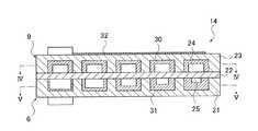
次に、本発明の反応装置を適用した実施形態における第二の反応装置14について図2〜図6を用いて説明する。ここで、図2は第二の反応装置14の斜視図であり、図3は図2の切断線III−IIIに沿った断面図であり、図4は図3の切断線IV−IVに沿った断面図であり、図5は図3の切断線V−Vに沿った断面図であり、図6は図5、図6の切断線VI−VIに沿った断面図である。  Next, the2nd reaction apparatus 14 in embodiment to which the reaction apparatus of this invention is applied is demonstrated using FIGS. Here, FIG. 2 is a perspective view of thesecond reactor 14, FIG. 3 is a cross-sectional view taken along the cutting line III-III in FIG. 2, and FIG. 4 is taken along the cutting line IV-IV in FIG. 5 is a cross-sectional view taken along the cutting line V-V in FIG. 3, and FIG. 6 is a cross-sectional view taken along the cutting line VI-VI in FIGS.

図2、図3、図6に示すように、第二の反応装置14はシリコン結晶、アルミニウム、ガラス等の中から選択された一又は複数の材料で形成された三枚の基板21,22,23を備え、これら三枚の基板21〜23が積み重ねて接合されたものが第二の反応装置14の本体となる。ここで、第二の燃焼器6の本体は、下側の下基板21と、挟持された中基板22とから構成され、改質器9の本体は、上側の上基板23と、中基板22とから構成され、中基板22が第二の燃焼器6と改質器9に共通している。なお、図3、図6では下基板21と上基板23を中基板22よりも厚く図示しているが、実際には基板21〜23は互いに同じ厚さであっても良い。また、基板21〜23はそれぞれ均一な厚さであるのが望ましい。また、基板21〜23は合板であっても良いし、多層基板であっても良いし、単板であっても良い。  As shown in FIGS. 2, 3, and 6, thesecond reactor 14 includes threesubstrates 21, 22, each made of one or more materials selected from silicon crystal, aluminum, glass, and the like. 23, and these threesubstrates 21 to 23 are stacked and joined to form a main body of thesecond reactor 14. Here, the main body of thesecond combustor 6 is composed of alower substrate 21 on the lower side and anintermediate substrate 22 sandwiched, and the main body of thereformer 9 is composed of anupper substrate 23 on the upper side and anintermediate substrate 22. Themiddle substrate 22 is common to thesecond combustor 6 and thereformer 9. 3 and 6, thelower substrate 21 and theupper substrate 23 are shown to be thicker than themiddle substrate 22, but thesubstrates 21 to 23 may actually have the same thickness. Moreover, it is desirable that thesubstrates 21 to 23 have a uniform thickness. Further, thesubstrates 21 to 23 may be plywood, a multilayer substrate, or a single plate.

図3〜図6に示すように、上基板23との中基板22との接合部には、接合面に沿った葛折り状の第一マイクロ流路24が形成されており、下基板21と中基板22との接合部には、接合面に沿った葛折り状の第二マイクロ流路25が形成されている。  As shown in FIG. 3 to FIG. 6, the firstmicro flow path 24 having a fold shape along the joint surface is formed at the joint portion between theupper substrate 23 and themiddle substrate 22. At the joint portion with themiddle substrate 22, a twistedsecond microchannel 25 is formed along the joint surface.

上基板23の中基板22との接合面(図3において上基板23の下面)には、葛折り状の溝が形成されており、この溝は上基板23と中基板22との接合前にフォトリソグラフィー、エッチング等を適宜施すことによって形成されたものである。この溝を覆うようにして上基板23を中基板22に接合することによって、溝が第一マイクロ流路24となっている。第一マイクロ流路24は、一端部から他端部にかけて一様な幅、一様な深さを有しながら延在している。この第一マイクロ流路24は、改質器9の流路である。  On the joint surface of theupper substrate 23 with the middle substrate 22 (the lower surface of theupper substrate 23 in FIG. 3), a crease-like groove is formed, and this groove is formed before theupper substrate 23 and themiddle substrate 22 are joined. It is formed by appropriately performing photolithography, etching and the like. By joining theupper substrate 23 to themiddle substrate 22 so as to cover the groove, the groove becomes thefirst microchannel 24. Thefirst microchannel 24 extends from one end to the other end while having a uniform width and a uniform depth. The firstmicro flow path 24 is a flow path of thereformer 9.

第一マイクロ流路24の一端部では、上基板23の接合面から接合面の反対面(図3において上基板23の上面)まで貫通した入口用の貫通孔26が形成されており、第一マイクロ流路24の他端部では、上基板23の接合面から反対面まで貫通した出口用の貫通孔27が形成されている。貫通孔26は管を介して第一の気化器3の出口に通じており、貫通孔27は別の管を介して一酸化炭素除去器10の入口に通じている。  At one end of thefirst microchannel 24, an inlet through-hole 26 penetrating from the bonding surface of theupper substrate 23 to the surface opposite to the bonding surface (the upper surface of theupper substrate 23 in FIG. 3) is formed. At the other end of themicrochannel 24, an outlet throughhole 27 that penetrates from the joint surface of theupper substrate 23 to the opposite surface is formed. The throughhole 26 communicates with the outlet of thefirst vaporizer 3 through a pipe, and the throughhole 27 communicates with the inlet of thecarbon monoxide remover 10 through another pipe.

第一マイクロ流路24の壁面特に、上基板23に形成された溝の底及び側面には、反応触媒としての改質触媒30が形成されている。改質触媒30は、メタノールと水を水素と二酸化炭素に改質する(上記化学反応式(1)参照)触媒であって、担体としてのアルミニウム酸化物に銅及び亜鉛を担持させたCuO−ZnO系触媒(CuO/ZnO/Al23)である。改質触媒30の膜厚は第一マイクロ流路24の一端部(入口)から他端部(出口)にかけて一様である。なお、改質触媒30の膜厚は第一マイクロ流路24の一端部(入口)から他端部(出口)にかけて連続的又は段階的に厚くなっていっても良い。A reformingcatalyst 30 as a reaction catalyst is formed on the wall surface of thefirst microchannel 24, particularly on the bottom and side surfaces of the groove formed in theupper substrate 23. The reformingcatalyst 30 is a catalyst for reforming methanol and water to hydrogen and carbon dioxide (see the above chemical reaction formula (1)), and is a CuO—ZnO in which copper and zinc are supported on an aluminum oxide as a support. It is a system catalyst (CuO / ZnO / Al2 O3 ). The film thickness of the reformingcatalyst 30 is uniform from one end (inlet) to the other end (outlet) of thefirst microchannel 24. The film thickness of the reformingcatalyst 30 may be increased continuously or stepwise from one end (inlet) to the other end (outlet) of thefirst microchannel 24.

下基板21の中基板22との接合面(図3において下基板21の上面)にも、葛折り状の溝が形成されており、下基板21が中基板22に接合されることによって溝が第二マイクロ流路25となっている。第二マイクロ流路25は、一端部から他端部にかけて一様な幅、一様な深さを有しながら延在している。この第二マイクロ流路25は、第二の燃焼器6の流路である。  A crease-like groove is also formed on the joint surface of thelower substrate 21 with the middle substrate 22 (the upper surface of thelower substrate 21 in FIG. 3), and the groove is formed by joining thelower substrate 21 to themiddle substrate 22. Asecond microchannel 25 is formed. Thesecond microchannel 25 extends from one end to the other end while having a uniform width and a uniform depth. The secondmicro flow path 25 is a flow path of thesecond combustor 6.

また、中基板22の両方の接合面と平行であり且つ両方の接合面の中間にある中間面に関して、第一マイクロ流路24と第二マイクロ流路25が互いに面対称になるように第一マイクロ流路24及び第二マイクロ流路25が形状加工されている。つまり、図3における上から下に向かって第二の反応装置14を見た(第二の反応装置14を平面視した)場合、第一マイクロ流路24が第二マイクロ流路25に重なっている。  In addition, thefirst microchannel 24 and thesecond microchannel 25 are symmetrical with respect to each other with respect to an intermediate surface that is parallel to both of the bonding surfaces of theintermediate substrate 22 and that is intermediate between both of the bonding surfaces. Themicrochannel 24 and thesecond microchannel 25 are processed. That is, when thesecond reactor 14 is viewed from the top to the bottom in FIG. 3 (when thesecond reactor 14 is viewed in plan), thefirst microchannel 24 overlaps thesecond microchannel 25. Yes.

第二マイクロ流路25の一端部では、下基板21の接合面から接合面の反対面(図3において下基板21の下面)まで貫通した入口用の貫通孔28が形成されており、第二マイクロ流路25の他端部には、下基板21の接合面から反対面まで貫通した出口用の貫通孔29が形成されている。貫通孔28は管を介して第二の気化器15に通じており、貫通孔29は別の管を介して発電装置1の外に通じている。  At one end of thesecond microchannel 25, an inlet throughhole 28 penetrating from the bonding surface of thelower substrate 21 to the opposite surface of the bonding surface (the lower surface of thelower substrate 21 in FIG. 3) is formed. At the other end of themicrochannel 25, an outlet through-hole 29 that penetrates from the joint surface of thelower substrate 21 to the opposite surface is formed. The throughhole 28 communicates with thesecond vaporizer 15 through a pipe, and the throughhole 29 communicates with the outside of thepower generator 1 through another pipe.

また、中基板22の両方の接合面と平行であり且つ両方の接合面の中間にある中間面に関して、貫通孔26が貫通孔28に対して対称配置されており、同様にその中間面に関して、貫通孔27が貫通孔29に対称配置されている。  Further, with respect to the intermediate surface that is parallel to both of the bonding surfaces of theintermediate substrate 22 and that is intermediate between both of the bonding surfaces, the throughholes 26 are arranged symmetrically with respect to the through holes 28. The throughhole 27 is arranged symmetrically with the throughhole 29.

第二マイクロ流路25の壁面特に、下基板21に形成された溝の底及び側面には、燃焼触媒31が形成されている。燃焼触媒31は、メタノールの酸化を促進する燃焼触媒であり、具体的には担体に白金を担持させたPt系触媒(Pt/Al23)である。担体は多孔質であり、特に多孔質金属酸化物が好ましく、多孔質金属酸化物として酸化アルミニウム、酸化チタン、酸化セリウム等を用いることができる。これら酸化アルミニウム、酸化チタン、酸化セリウム等のうち二種以上を用いても良い。燃焼触媒31は、燃焼触媒31の膜厚は第二マイクロ流路25の一端部(入口)から他端部(出口)にかけて連続的又は段階的に厚くなっていく。Acombustion catalyst 31 is formed on the wall surface of thesecond microchannel 25, particularly on the bottom and side surfaces of the groove formed in thelower substrate 21. Thecombustion catalyst 31 is a combustion catalyst that promotes the oxidation of methanol. Specifically, thecombustion catalyst 31 is a Pt-based catalyst (Pt / Al2 O3 ) in which platinum is supported on a carrier. The support is porous, and a porous metal oxide is particularly preferable. Aluminum oxide, titanium oxide, cerium oxide, or the like can be used as the porous metal oxide. Two or more of these aluminum oxide, titanium oxide, cerium oxide and the like may be used. Thecombustion catalyst 31 has a film thickness that increases continuously or stepwise from one end (inlet) to the other end (outlet) of thesecond microchannel 25.

上基板23の接合面とは反対側の面(図3において上基板23の上面)には、葛折り状に呈した電熱ヒータ32が配設されている。電熱ヒータ32は、電気抵抗性発熱体,半導体性発熱体等を薄膜状に成膜したものであり、電流が流れたり電圧が印加されたりすることによって電気エネルギーで発熱するものである。  On the surface opposite to the bonding surface of the upper substrate 23 (the upper surface of theupper substrate 23 in FIG. 3), anelectric heater 32 having a twisted shape is disposed. Theelectric heater 32 is a thin film formed of an electric resistance heating element, a semiconductor heating element, etc., and generates heat by electric energy when a current flows or a voltage is applied.

第一の反応装置13について図7を用いて説明する。図7は、第一の反応装置13の断面図である。図7に示すように、第一の反応装置13において、第二の反応装置14のいずれかの部分と対応する部分に対して、下二桁が同じとなる符号を付す。  Thefirst reactor 13 will be described with reference to FIG. FIG. 7 is a cross-sectional view of thefirst reactor 13. As shown in FIG. 7, in the1st reaction apparatus 13, the code | symbol from which the last two digits are the same is attached | subjected with respect to the part corresponding to any part of the2nd reaction apparatus 14. FIG.

第一の反応装置13は、第二の反応装置14とほぼ同様の構成となっている。つまり、第一の反応装置13は、下基板121、中基板122及び上基板123をこの順に積み重ねて接合した本体を有する。第一の反応装置13と第二の反応装置14の異なる点としては、第二の反応装置14では第一マイクロ流路24の壁面に改質触媒30が形成されているのに対し、第一の反応装置13では、上基板123と中基板122との接合部に形成された第一マイクロ流路124の壁面には触媒が形成されていないことである。この第一マイクロ流路124が第一の気化器3の流路であり、下基板121と中基板122との接合部に形成された第二マイクロ流路125が第一の燃焼器5の流路である。更には、第一マイクロ流路124の一端部に通じる入口用の貫通孔は、管を介して第一の燃料ポンプ7に通じており、第一マイクロ流路124の他端部に通じる出口用の貫通孔は、別の管を介して第二の反応装置14の入口用の貫通孔26に通じている。以上のことを除いて、第一の反応装置13は第二の反応装置14と同じに構成されており、第一の反応装置13においては、第二の反応装置14のいずれかの部分と対応する部分についての説明は省略する。  Thefirst reactor 13 has substantially the same configuration as thesecond reactor 14. That is, thefirst reactor 13 has a main body in which thelower substrate 121, themiddle substrate 122, and theupper substrate 123 are stacked and joined in this order. The difference between thefirst reactor 13 and thesecond reactor 14 is that the reformingcatalyst 30 is formed on the wall surface of thefirst microchannel 24 in thesecond reactor 14, whereas thefirst reactor 13 and thesecond reactor 14 are different from each other. In thereactor 13, the catalyst is not formed on the wall surface of thefirst microchannel 124 formed at the joint between theupper substrate 123 and themiddle substrate 122. Thefirst microchannel 124 is the channel of thefirst vaporizer 3, and thesecond microchannel 125 formed at the joint between thelower substrate 121 and themiddle substrate 122 is the flow of thefirst combustor 5. Road. Furthermore, the inlet through hole that communicates with one end of thefirst microchannel 124 communicates with thefirst fuel pump 7 via a pipe, and the outlet through hole that communicates with the other end of thefirst microchannel 124. This through hole communicates with the inlet throughhole 26 of thesecond reactor 14 through another pipe. Except for the above, thefirst reactor 13 is configured in the same manner as thesecond reactor 14, and thefirst reactor 13 corresponds to any part of thesecond reactor 14. A description of the parts to be performed is omitted.

次に、発電装置1の動作、第一の反応装置13を用いた反応方法、第二の反応装置14を用いた反応方法について説明する。
まず、反応物が充填された第一の燃料容器2を電子機器本体に装着するとともに、燃料が充填された第二の燃料容器4を電子機器本体に装着する。次いで、第一の燃料ポンプ7、第二の燃料ポンプ8及び空気ポンプ12を作動させ、電熱ヒータ32,132に電圧を印加して、電熱ヒータ32,132を発熱させる。
Next, the operation of thepower generation device 1, the reaction method using thefirst reaction device 13, and the reaction method using thesecond reaction device 14 will be described.
First, thefirst fuel container 2 filled with the reactant is attached to the electronic device body, and thesecond fuel container 4 filled with fuel is attached to the electronic device body. Next, thefirst fuel pump 7, thesecond fuel pump 8, and theair pump 12 are operated, and a voltage is applied to theelectric heaters 32 and 132 to cause theelectric heaters 32 and 132 to generate heat.

第二の燃料ポンプ8が作動すると、第二の燃料容器4内の燃料が第二の気化器15に供給され、第二の気化器15中で燃料が気化する。気化した燃料は、空気ポンプ12によって取り込まれた空気と混合して第一の燃焼器5、第二の燃焼器6それぞれに供給される。  When thesecond fuel pump 8 is operated, the fuel in thesecond fuel container 4 is supplied to thesecond carburetor 15, and the fuel is vaporized in thesecond carburetor 15. The vaporized fuel is mixed with the air taken in by theair pump 12 and supplied to thefirst combustor 5 and thesecond combustor 6, respectively.

第一の燃焼器5では、燃料と空気の混合気が、第二マイクロ流路125の一端部に通じる入口用の貫通孔から第二マイクロ流路125に流入する。第二マイクロ流路125に流入した燃料と空気の混合気は、第二マイクロ流路125の他端部に向かって流動する。ここで、燃料と空気の混合気が燃焼触媒131によって燃焼する。これにより燃料が酸化し、燃焼熱が発生する。第二マイクロ流路125の中で生成された生成物は、第二マイクロ流路125の他端部に通じる出口用の貫通孔から外部に排出される。  In thefirst combustor 5, the mixture of fuel and air flows into thesecond microchannel 125 from the inlet through hole that communicates with one end of thesecond microchannel 125. The fuel / air mixture flowing into thesecond microchannel 125 flows toward the other end of thesecond microchannel 125. Here, the fuel / air mixture is burned by thecombustion catalyst 131. This oxidizes the fuel and generates combustion heat. The product generated in thesecond microchannel 125 is discharged to the outside from a through-hole for an outlet communicating with the other end of thesecond microchannel 125.

第二の燃焼器6でも同様に、燃料と空気の混合気が入口用の貫通孔28から第二マイクロ流路25に流入する。第二マイクロ流路25に流入した混合気が第二マイクロ流路25の他端部に向かって流動し、その混合気が流動中に燃焼触媒31によって燃焼する。これにより、燃料が酸化し、燃焼熱が発生する。第二マイクロ流路25の中で生成された生成物は、出口用の貫通孔29から外部に排出される。  Similarly, in thesecond combustor 6, the mixture of fuel and air flows into thesecond microchannel 25 from the throughhole 28 for inlet. The air-fuel mixture flowing into thesecond microchannel 25 flows toward the other end of thesecond microchannel 25, and the air-fuel mixture burns by thecombustion catalyst 31 during the flow. As a result, the fuel is oxidized and combustion heat is generated. The product generated in thesecond microchannel 25 is discharged to the outside through the outlet throughhole 29.

一方、第一の燃料ポンプ7が作動すると、第一の燃料容器2内の反応物が第一の気化器3に供給される。第一の気化器3では、反応物が、第一マイクロ流路124の一端部に通じる入口用の貫通孔から第一マイクロ流路124に流入する。第一マイクロ流路124に流入した反応物は、第一マイクロ流路124の他端部に向かって流動する。ここで、第一マイクロ流路124を流動中の反応物は、電熱ヒータ132で発した熱及び第一の燃焼器5で発した燃焼熱により加熱されて気化する。第一マイクロ流路124の中で気化した反応物は、第一マイクロ流路124の他端部に通じる出口用の貫通孔から改質器9に供給される。  On the other hand, when thefirst fuel pump 7 is operated, the reactant in thefirst fuel container 2 is supplied to thefirst vaporizer 3. In thefirst vaporizer 3, the reactant flows into thefirst microchannel 124 from the inlet through hole that communicates with one end of thefirst microchannel 124. The reactant that has flowed into thefirst microchannel 124 flows toward the other end of thefirst microchannel 124. Here, the reactant flowing in thefirst microchannel 124 is heated and vaporized by heat generated by theelectric heater 132 and combustion heat generated by thefirst combustor 5. The reactant vaporized in thefirst microchannel 124 is supplied to thereformer 9 through an outlet through hole that communicates with the other end of thefirst microchannel 124.

改質器9では、気化した反応物が入口用の貫通孔26から第一マイクロ流路24に流入する。第一マイクロ流路24に流入した反応物が第一マイクロ流路24の他端部に向かって流動し、その混合気が流動中に電熱ヒータ32で発した熱及び第二の燃焼器6で発した燃焼熱により加熱される。これにより、反応物が、改質触媒30の作用を受けて二酸化炭素と水素に改質される。第一マイクロ流路24の中で生成された生成物は、出口用の貫通孔27から一酸化炭素除去器10に供給される。  In thereformer 9, the vaporized reactant flows into thefirst microchannel 24 from the inlet throughhole 26. The reactant that has flowed into thefirst microchannel 24 flows toward the other end of thefirst microchannel 24, and the mixture is heated by theelectric heater 32 during the flow and thesecond combustor 6. It is heated by the generated combustion heat. As a result, the reaction product is reformed into carbon dioxide and hydrogen under the action of the reformingcatalyst 30. The product generated in thefirst microchannel 24 is supplied to thecarbon monoxide remover 10 from the outlet throughhole 27.

一酸化炭素除去器10では、改質器9から供給された混合気中の一酸化炭素が除去される。そして、一酸化炭素除去器10から燃料電池11の燃料極に混合気が供給され、空気ポンプ12によって空気が燃料電池11の空気極に供給され、燃料電池11における水素と酸素の電気化学反応により電気エネルギーが生成される。なお、一酸化炭素除去器10では、燃焼器が設けられていないが、反応に熱を要する場合、第三の燃焼器を設けてもよい。  In thecarbon monoxide remover 10, carbon monoxide in the air-fuel mixture supplied from thereformer 9 is removed. Then, the air-fuel mixture is supplied from thecarbon monoxide remover 10 to the fuel electrode of the fuel cell 11, air is supplied to the air electrode of the fuel cell 11 by theair pump 12, and the electrochemical reaction of hydrogen and oxygen in the fuel cell 11 Electric energy is generated. Thecarbon monoxide remover 10 is not provided with a combustor, but a third combustor may be provided when heat is required for the reaction.

ここで、第一の反応装置13に着目すると、中基板122の両接合面の間の中間面に関して、第一マイクロ流路124と第二マイクロ流路125が互いに面対称である。更に、第一マイクロ流路124の入口の貫通孔と第二マイクロ流路125の入口の貫通孔が中間面に関して対称配置されており、第一マイクロ流路124の出口の貫通孔と第二マイクロ流路125の出口の貫通孔が中間面に関して対称配置されている。従って、第一マイクロ流路124に沿って反応物が流動する方向は、第二マイクロ流路125に沿って燃料と空気の混合気が流動する方向と同じである。  Here, when paying attention to thefirst reaction apparatus 13, the firstmicro flow path 124 and the secondmicro flow path 125 are plane-symmetric with respect to an intermediate surface between both the joint surfaces of theintermediate substrate 122. Furthermore, the through hole at the inlet of thefirst microchannel 124 and the throughhole at the inlet of thesecond microchannel 125 are arranged symmetrically with respect to the intermediate surface, and the through hole at the outlet of thefirst microchannel 124 and thesecond microchannel 124 are arranged. The through holes at the outlet of theflow path 125 are arranged symmetrically with respect to the intermediate plane. Therefore, the direction in which the reactant flows along thefirst microchannel 124 is the same as the direction in which the fuel / air mixture flows along thesecond microchannel 125.

ところで、反応物が第一マイクロ流路124を進むにつれて、液体成分が減っていき気体成分が多くなるので、第一マイクロ流路124の出口側では入口側よりも反応物の気化に要する熱量が少なくても済む。そして、燃料が第二マイクロ流路125を進むにつれて、燃料の割合が減っていき生成物の割合が増えていくので、第二マイクロ流路125の出口側では入口側よりも燃焼熱量が小さい。第一マイクロ流路124が中間面に関し第二マイクロ流路125と面対称であり、反応物の流動方向が燃料の流動方向と同じであるから、反応物の気化熱量をより必要とするところでは、燃料の燃焼熱量をより多く発生させ、反応物の気化熱量をあまり必要としないところでは、燃料の燃焼熱量をより少なく発生させている。従って、気化により吸収する熱量を第一の燃焼器5で過不足無く供給することができる。そのため、電熱ヒータ132による供給熱量を少なくすることができ、発電装置1全体のエネルギー効率が向上する。  By the way, as the reactant proceeds through thefirst microchannel 124, the liquid component decreases and the gas component increases, so that the amount of heat required for vaporizing the reactant is larger at the outlet side of thefirst microchannel 124 than at the inlet side. Less is enough. As the fuel travels through thesecond microchannel 125, the ratio of the fuel decreases and the ratio of the product increases. Therefore, the amount of combustion heat is smaller on the outlet side of thesecond microchannel 125 than on the inlet side. Since the firstmicro flow path 124 is plane-symmetric with the secondmicro flow path 125 with respect to the intermediate surface, and the flow direction of the reactant is the same as the flow direction of the fuel, the amount of heat of vaporization of the reactant is more required. Where the amount of heat of combustion of the fuel is increased and the amount of heat of vaporization of the reactant is not so much required, the amount of heat of combustion of the fuel is generated less. Accordingly, the amount of heat absorbed by vaporization can be supplied by thefirst combustor 5 without excess or deficiency. Therefore, the amount of heat supplied by theelectric heater 132 can be reduced, and the energy efficiency of theentire power generator 1 is improved.

第二の反応装置14に着目しても、中基板22の両接合面の間の中間面に関して、第一マイクロ流路24と第二マイクロ流路25が互いに面対称である。更に、入口の貫通孔26と貫通孔28が中間面に関して対称配置されており、出口の貫通孔27と貫通孔29が中間面に関して対称配置されている。従って、第一マイクロ流路24に沿った反応物の流動方向は、第二マイクロ流路25に沿った燃料の流動方向と同じである。そのため、反応物の改質に要する吸熱量をより必要とするところでは、燃料の燃焼熱量をより多く発生させ、反応物の改質に要する吸熱量をあまり必要としないところでは、燃料の燃焼熱量をより少なく発生させている。従って、改質により吸収する熱量を第二の燃焼器6で過不足無く供給することができる。そのため、電熱ヒータ32による供給熱量を少なくすることができ、発電装置1全体のエネルギー効率が向上する。  Even if attention is paid to thesecond reaction apparatus 14, the firstmicro flow path 24 and the secondmicro flow path 25 are plane-symmetric with respect to the intermediate surface between both joint surfaces of theintermediate substrate 22. Further, the inlet throughhole 26 and the throughhole 28 are arranged symmetrically with respect to the intermediate surface, and the outlet throughhole 27 and the throughhole 29 are arranged symmetrically with respect to the intermediate surface. Therefore, the flow direction of the reactant along thefirst microchannel 24 is the same as the flow direction of the fuel along thesecond microchannel 25. Therefore, where more heat absorption is required to reform the reactant, more heat is generated from the combustion of the fuel, and where less heat is required to reform the reactant, the heat of combustion of the fuel is greater. Is generated less. Accordingly, the amount of heat absorbed by the reforming can be supplied by thesecond combustor 6 without excess or deficiency. Therefore, the amount of heat supplied by theelectric heater 32 can be reduced, and the energy efficiency of theentire power generator 1 is improved.

また、燃焼触媒31の膜厚が第二マイクロ流路25の入口から出口にかけて一様ではなく、入口から出口にかけて厚くなっているので、対応する位置においては、反応物の改質による吸熱量と第二燃焼の燃焼による発熱量が同じとなる。そのため、改質により吸収する熱量を第二の燃焼器6で過不足無く供給することができる。  Further, since the film thickness of thecombustion catalyst 31 is not uniform from the inlet to the outlet of thesecond micro-channel 25 and is thicker from the inlet to the outlet, at the corresponding position, the endothermic amount due to the reforming of the reactant and The amount of heat generated by the combustion of the second combustion is the same. Therefore, the amount of heat absorbed by the reforming can be supplied by thesecond combustor 6 without excess or deficiency.

なお、上記実施形態における第二の反応装置14の代わりに、図8に示すような第二の反応装置214を発電装置1に設けても良い。別の第二の反応装置214について図8を用いて説明する。図8は、第二の反応装置214の断面図である。図8に示すように、第二の反応装置214において、上記第二の反応装置14のいずれかの部分と対応する部分に対して、下二桁が同じとなる符号を付す。  In addition, you may provide the2nd reactor 214 as shown in FIG. 8 in the electricpower generating apparatus 1 instead of the2nd reactor 14 in the said embodiment. Anothersecond reactor 214 will be described with reference to FIG. FIG. 8 is a cross-sectional view of thesecond reactor 214. As shown in FIG. 8, in thesecond reactor 214, parts corresponding to any part of thesecond reactor 14 are given the same reference numerals in the last two digits.

別の第二の反応装置214は、上記第二の反応装置14とほぼ同様の構成となっている。つまり、別の第二の反応装置214は下基板221、中基板222及び上基板223をこの順に積み重ねて接合した本体を有し、下基板221と中基板222を接合したものが第二の燃焼器206の本体であり、中基板222と上基板223を接合したものが改質器209の本体であり、中基板222が第二の燃焼器206と改質器209に共通している。  Anothersecond reactor 214 has substantially the same configuration as thesecond reactor 14 described above. That is, anothersecond reactor 214 has a main body in which thelower substrate 221, themiddle substrate 222, and theupper substrate 223 are stacked and joined in this order, and thelower substrate 221 and themiddle substrate 222 joined together are the second combustion. The main body of thecombustor 206 is obtained by joining themiddle substrate 222 and theupper substrate 223 to the main body of thereformer 209, and themiddle substrate 222 is common to thesecond combustor 206 and thereformer 209.

この第二の反応装置214と上記第二の反応装置14の異なる点としては、上記第二の反応装置14では、第二マイクロ流路25となる溝が下基板21の接合面に形成されているとともに第一マイクロ流路24となる溝が上基板23の接合面に形成されているのに対し、この第二の反応装置214では中基板222の両面にそれぞれ第一マイクロ流路224の溝と第二マイクロ流路225の溝が形成されている。  A difference between thesecond reaction device 214 and thesecond reaction device 14 is that thesecond reaction device 14 has a groove that forms thesecond microchannel 25 formed on the bonding surface of thelower substrate 21. In addition, a groove serving as thefirst microchannel 24 is formed on the bonding surface of theupper substrate 23, whereas in thesecond reactor 214, a groove of thefirst microchannel 224 is formed on both surfaces of themiddle substrate 222, respectively. And a groove of thesecond microchannel 225 is formed.

以上のことを除いて、この第二の反応装置214は上記第二の反応装置14と同じに構成されている。つまり、第一マイクロ流路224の壁面に改質触媒230が形成され、第二マイクロ流路225の壁面に燃焼触媒231が形成され、中基板222の両接合面の間の中間面に関し、第一マイクロ流路224と第二マイクロ流路225が互いに面対称であり、第一マイクロ流路224の入口の貫通孔が中間面に関して第二マイクロ流路225の入口の貫通孔と対称配置され、第一マイクロ流路224の出口の貫通孔が中間面に関して第二マイクロ流路225の出口の貫通孔と対称配置されている。従って、気化した反応物が第一マイクロ流路224を流れる方向が気化した燃料が第二マイクロ流路225を流れる方向と同じである。なお、図8において、中基板222を下基板221及び上基板223よりも厚く図示しているが、実際には基板221〜223は同じ厚さであるのが望ましい。  Except for the above, thesecond reactor 214 is configured in the same manner as thesecond reactor 14 described above. That is, the reformingcatalyst 230 is formed on the wall surface of thefirst microchannel 224, thecombustion catalyst 231 is formed on the wall surface of thesecond microchannel 225, and the intermediate surface between both joint surfaces of theintermediate substrate 222 is The onemicrochannel 224 and thesecond microchannel 225 are plane-symmetric with each other, and the through hole at the inlet of thefirst microchannel 224 is symmetrically arranged with the through hole at the inlet of thesecond microchannel 225 with respect to the intermediate surface. The through hole at the outlet of thefirst microchannel 224 is arranged symmetrically with the through hole at the outlet of thesecond microchannel 225 with respect to the intermediate surface. Therefore, the direction in which the vaporized reactant flows through thefirst microchannel 224 is the same as the direction in which the vaporized fuel flows through thesecond microchannel 225. In FIG. 8, themiddle substrate 222 is shown to be thicker than thelower substrate 221 and theupper substrate 223, but it is actually desirable that thesubstrates 221 to 223 have the same thickness.

以下に、実施例を挙げることにより、本発明について更に具体的に説明する。
第二の反応装置14の吸熱量及び発熱量をシミュレーションによって求めた。
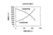
ここで、マイクロ流路24,25の入口から出口までの長さを233mm、マイクロ流路24,25の深さを0.5mm、マイクロ流路24,25の幅を0.6mmとし、改質触媒30及び燃焼触媒31の膜厚を一様として、第二の反応装置14をモデリングした。そして、上記実施形態のように、反応物としてのメタノールと水の混合気を1.48ml/hの供給量で第一マイクロ流路24を流動させ、燃料としてメタノールの気体を0.6ml/hの供給量で第二マイクロ流路25を流動させた場合に、第一マイクロ流路24の各点での吸熱量と第二マイクロ流路25の各点での吸熱量をシミュレーションにより求めた。第一マイクロ流路24における反応物の流動方向が第二マイクロ流路25における燃料の流動方向と同じである場合、つまり、反応物及び燃料をそれぞれの第一マイクロ流路24の入口から出口に向かって流動させた場合の結果を図9に示す。一方、第一マイクロ流路24における反応物の流動方向が第二マイクロ流路25における燃料の流動方向と逆である場合、つまり、反応物は第一マイクロ流路24の入口から出口に向かって流動させ、燃料は逆に第二マイクロ流路25の出口から入口に向かって流動させた場合の結果を図10に示す。
Hereinafter, the present invention will be described more specifically with reference to examples.
The endothermic amount and calorific value of thesecond reactor 14 were determined by simulation.
Here, the length from the inlet to the outlet of themicrochannels 24 and 25 is 233 mm, the depth of themicrochannels 24 and 25 is 0.5 mm, and the width of themicrochannels 24 and 25 is 0.6 mm. Thesecond reactor 14 was modeled with uniform film thicknesses of thecatalyst 30 and thecombustion catalyst 31. Then, as in the above embodiment, a mixture of methanol and water as a reactant is caused to flow through thefirst microchannel 24 at a supply rate of 1.48 ml / h, and methanol gas as fuel is 0.6 ml / h. When thesecond microchannel 25 was caused to flow with the supplied amount, the endothermic amount at each point of thefirst microchannel 24 and the endothermic amount at each point of thesecond microchannel 25 were obtained by simulation. When the flow direction of the reactant in thefirst microchannel 24 is the same as the flow direction of the fuel in thesecond microchannel 25, that is, the reactant and the fuel are transferred from the inlet to the outlet of eachfirst microchannel 24. FIG. 9 shows the result when the fluid is made to flow. On the other hand, when the flow direction of the reactant in thefirst microchannel 24 is opposite to the flow direction of the fuel in thesecond microchannel 25, that is, the reactant flows from the inlet of thefirst microchannel 24 toward the outlet. FIG. 10 shows the result when the fuel is made to flow and the fuel is made to flow from the outlet of thesecond microchannel 25 toward the inlet.

図9,10において、縦軸は熱量を表し、横軸はマイクロ流路24,25それぞれの入口の位置をゼロとした場合、入口からの長さ(流路位置)を表す。
反応物と燃料を同じ方向に流動させた場合、図9に示すように、改質器9における吸熱量は第一マイクロ流路24の入口側で大きく、出口側で小さく、第二の燃焼器6における発熱量は第二マイクロ流路25の入口側で大きく、出口側で小さいことがわかる。従って、対応する位置において、反応物の改質により吸収する熱量を第二の燃焼器6で過不足無く供給することができることがわかる。
9 and 10, the vertical axis represents the amount of heat, and the horizontal axis represents the length (flow path position) from the inlet when the position of the inlet of each of themicro flow paths 24 and 25 is zero.
When the reactant and the fuel flow in the same direction, as shown in FIG. 9, the heat absorption amount in thereformer 9 is large on the inlet side of thefirst microchannel 24 and small on the outlet side, and the second combustor It can be seen that the heat generation amount at 6 is large at the inlet side of thesecond microchannel 25 and small at the outlet side. Therefore, it can be seen that the amount of heat absorbed by the reforming of the reactant can be supplied by thesecond combustor 6 without excess or deficiency at the corresponding position.

また、反応物と燃料を逆方向に流動させた場合、図10に示すように、改質器9における吸熱量は第一マイクロ流路24の入口側で大きく、出口側で小さいが、第二の燃焼器6における発熱量は第二マイクロ流路25の入口側で小さく、出口側で大きいことがわかる。  Further, when the reactant and the fuel are caused to flow in opposite directions, the endothermic amount in thereformer 9 is large at the inlet side of thefirst microchannel 24 and small at the outlet side, as shown in FIG. It can be seen that the amount of heat generated in thecombustor 6 is small on the inlet side of thesecond microchannel 25 and large on the outlet side.

また、図9に示すように、発熱量の流路位置に対する減少が第二マイクロ流路25に沿った中央付近で急峻であり、改質器9の吸熱量は同じ位置における第二の燃焼器6の発熱量と等しくない。これは、燃料の燃焼反応のメタノール濃度次数が、反応物の改質反応の次数に比較して大きいためである。そこで、図11に示すように燃焼触媒31の膜厚を第二マイクロ流路25の入口から出口にかけて段階的に厚くしたら、第一マイクロ流路24に沿った温度分布は図12のようになった。このようにすることによって、改質器9の吸熱量は同じ位置における第二の燃焼器6の発熱量と等しくすることができ、位置毎に異なる改質器9の吸熱量によって温度の低下を、第二マイクロ流路25内での位置毎に燃焼反応の程度を変えることで補償するために、第一マイクロ流路24内が常に均等な温度に設定できるので、第一マイクロ流路24内が冷えることによって或いは過熱することによって反応の進行が遅れたり、本来第一マイクロ流路24内で必要な反応と異なる反応を引き起こすことを抑制できる。ここで、図11において、縦軸は燃焼触媒31の厚さを表し、横軸は第二マイクロ流路25の入口からの長さ(流路位置)を表す。図12において、縦軸は温度を表し、横軸は第二マイクロ流路25の入口からの長さ(流路位置)を表す。  Further, as shown in FIG. 9, the decrease in the calorific value with respect to the flow path position is steep near the center along the secondmicro flow path 25, and the heat absorption amount of thereformer 9 is the second combustor at the same position. It is not equal to 6 calorific value. This is because the methanol concentration order of the fuel combustion reaction is larger than the order of the reforming reaction of the reactant. Therefore, if the film thickness of thecombustion catalyst 31 is increased stepwise from the inlet to the outlet of thesecond microchannel 25 as shown in FIG. 11, the temperature distribution along thefirst microchannel 24 is as shown in FIG. It was. By doing in this way, the heat absorption amount of thereformer 9 can be made equal to the heat generation amount of thesecond combustor 6 at the same position, and the temperature is lowered due to the heat absorption amount of thereformer 9 which is different for each position. In order to compensate by changing the degree of the combustion reaction for each position in thesecond microchannel 25, the inside of thefirst microchannel 24 can always be set at a uniform temperature. It is possible to suppress the reaction from being delayed due to cooling or overheating, or to cause a reaction different from the reaction that is originally required in thefirst microchannel 24. Here, in FIG. 11, the vertical axis represents the thickness of thecombustion catalyst 31, and the horizontal axis represents the length (flow path position) from the inlet of the secondmicro flow path 25. In FIG. 12, the vertical axis represents temperature, and the horizontal axis represents the length from the inlet of the second microchannel 25 (channel position).

発電装置1のブロック図である。1 is a block diagram of apower generator 1. FIG.本発明の実施の形態における第二の反応装置14の斜視図である。It is a perspective view of the2nd reactor 14 in an embodiment of the invention.図2に示した切断線III−IIIに沿った断面図である。FIG. 3 is a cross-sectional view taken along a cutting line III-III shown in FIG. 2.図3に示した切断線IV−IVに沿った断面図である。FIG. 4 is a cross-sectional view taken along a cutting line IV-IV shown in FIG. 3.図3に示した切断線V−Vに沿った断面図である。FIG. 5 is a cross-sectional view taken along a cutting line VV shown in FIG. 3.図4、図5に示した切断線VI−VIに沿った断面図である。FIG. 6 is a cross-sectional view taken along a cutting line VI-VI shown in FIGS. 4 and 5.本発明の実施の形態における第一の反応装置13の断面図である。It is sectional drawing of the1st reaction apparatus 13 in embodiment of this invention.本発明の実施の形態における第二の反応装置214の断面図である。It is sectional drawing of the2nd reaction apparatus 214 in embodiment of this invention.反応物と燃料を同一方向に流した場合、流路の位置と熱量との関係を示したグラフである。It is the graph which showed the relationship between the position of a flow path, and calorie | heat amount when a reactant and a fuel are flowed in the same direction.反応物と燃料を逆方向に流した場合、流路の位置と熱量との関係を示したグラフである。It is the graph which showed the relationship between the position of a flow path, and calorie | heat amount when a reactant and fuel are flowed in the reverse direction.流路の位置と燃焼触媒の厚さとの関係を示したグラフである。It is the graph which showed the relationship between the position of a flow path, and the thickness of a combustion catalyst.流路の位置と温度との関係を示したグラフである。It is the graph which showed the relationship between the position of a flow path, and temperature.

符号の説明Explanation of symbols

13 … 第一の反応装置
14 … 第二の反応装置
22〜23 … 基板(本体)
24 … 第一マイクロ流路(第一流路)
25 … 第二マイクロ流路(第二流路)
26 … 貫通孔(第一の入口)
27 … 貫通孔(第一の出口)
28 … 貫通孔(第二の入口)
29 … 貫通孔(第二の出口)
30 … 改質触媒(反応触媒)
31 … 燃焼触媒
32 … 電熱ヒータ(電熱膜)
121〜123 … 基板(本体)
124 … 第一マイクロ流路(第一流路)
125 … 第二マイクロ流路(第二流路)
131 … 燃焼触媒
132 … 電熱ヒータ
214 … 第二の反応装置
221〜223 … 基板(本体)
224 … 第一マイクロ流路(第一流路)
225 … 第二マイクロ流路(第二流路)
230 … 改質触媒(反応触媒)
231 … 燃焼触媒
232 … 電熱ヒータ(電熱膜)
DESCRIPTION OFSYMBOLS 13 ...1st reactor 14 ... 2nd reactor 22-23 ... Board | substrate (main body)
24 ... 1st micro flow path (1st flow path)
25 ... Second micro channel (second channel)
26 ... Through hole (first inlet)
27 ... Through hole (first outlet)
28 ... Through hole (second inlet)
29 ... Through hole (second outlet)
30 ... Reforming catalyst (reaction catalyst)
31 ...Combustion catalyst 32 ... Electric heater (electric heating film)
121-123 ... Substrate (main body)
124 ... 1st micro flow path (1st flow path)
125 ... Second micro-channel (second channel)
131 ...Combustion catalyst 132 ...Electric heater 214 ... Second reactor 221-223 ... Substrate (main body)
224 ... 1st microchannel (1st channel)
225 ... Second micro channel (second channel)
230… Reforming catalyst (reaction catalyst)
231 ...Combustion catalyst 232 ... Electric heater (electric heating film)

Claims (10)

Translated fromJapanese
本体と、燃料を燃焼させる燃焼触媒と、を有し、
反応物が流れる第一の流路及び燃料が流れる第二の流路が前記本体を通った所定の面に関して互いに面対称となるように前記本体の内部に形成され、前記燃焼触媒が前記第二の流路の壁面に形成されていることを特徴とする反応装置。
A main body and a combustion catalyst for burning fuel;
The first flow path through which the reactant flows and the second flow path through which the fuel flows are formed in the main body so as to be symmetrical with each other with respect to a predetermined plane passing through the main body, and the combustion catalyst is formed in the second flow path. It is formed in the wall surface of this flow path.
反応物が前記第一の流路を流れる方向は燃料が前記第二の流路を流れる方向と同じであることを特徴とする請求項2に記載の反応装置。  The reaction apparatus according to claim 2, wherein the direction in which the reactant flows through the first flow path is the same as the direction in which the fuel flows through the second flow path. 前記第一の流路の一端部にまで通じる第一の入口と、前記第二の流路の一端部にまで通じる第二の入口とが前記本体に形成され、前記所定の面に関して前記第一の入口と第二の入口が互いに対称配置されていることを特徴とする請求項1又は2に記載の反応装置。  A first inlet that leads to one end of the first flow path and a second inlet that leads to one end of the second flow path are formed in the main body, and the first inlet with respect to the predetermined surface The reaction apparatus according to claim 1, wherein the inlet and the second inlet are arranged symmetrically with respect to each other. 前記第一の流路の他端部にまで通じる第一の出口と、前記第二の流路の他端部にまで通じる第二の出口とが前記本体に形成され、前記所定の面に関して前記第第一の出口と前記第二の出口が互いに対称配置されていることを特徴とする請求項1から3のいずれか一項に記載の反応装置。  A first outlet leading to the other end of the first flow path and a second outlet leading to the other end of the second flow path are formed in the main body, and the predetermined surface is The reaction apparatus according to any one of claims 1 to 3, wherein the first outlet and the second outlet are arranged symmetrically to each other. 前記燃焼触媒の厚さが前記第二の流路の一端部から他端部にかけて不均一であることを特徴とする請求項1から4のいずれか一項に記載の反応装置。  The reactor according to any one of claims 1 to 4, wherein the combustion catalyst has a non-uniform thickness from one end to the other end of the second flow path. 反応物を反応させる反応触媒が前記第一の流路の壁面に形成されていることを特徴とする請求項1から5のいずれか一項に記載の反応装置。  The reaction apparatus according to any one of claims 1 to 5, wherein a reaction catalyst for reacting a reactant is formed on a wall surface of the first flow path. 前記反応触媒が反応物としてのメタノールと水を水素と二酸化炭素に反応させる触媒であることを特徴とする請求項6に記載の反応装置。  The reaction apparatus according to claim 6, wherein the reaction catalyst is a catalyst for reacting methanol and water as reactants with hydrogen and carbon dioxide. 前記燃焼触媒が燃料としてのメタノールを燃焼させる触媒であることを特徴とする請求項1から7のいずれか一項に記載の反応装置。  The reaction apparatus according to claim 1, wherein the combustion catalyst is a catalyst that burns methanol as a fuel. 発熱する電熱膜が前記本体の外面に形成されていることを特徴とする請求項1から8のいずれか一項に記載の反応装置。  The reaction apparatus according to any one of claims 1 to 8, wherein an electrothermal film that generates heat is formed on an outer surface of the main body. 請求項1から9のいずれか一項に記載の反応装置を用い、
反応物を前記第一の流路に流すとともに、その反応物が前記第一の流路を流れる方向と同じとなるように燃料を前記第二の流路に流すことを特徴とする反応方法。
Using the reactor according to any one of claims 1 to 9,
A reaction method characterized by causing a reactant to flow through the first channel and flowing fuel into the second channel so that the reactant flows in the same direction as the first channel.
JP2003338542A2003-09-292003-09-29 Reaction apparatus and reaction methodPendingJP2005103399A (en)

Priority Applications (1)

Application NumberPriority DateFiling DateTitle
JP2003338542AJP2005103399A (en)2003-09-292003-09-29 Reaction apparatus and reaction method

Applications Claiming Priority (1)

Application NumberPriority DateFiling DateTitle
JP2003338542AJP2005103399A (en)2003-09-292003-09-29 Reaction apparatus and reaction method

Publications (1)

Publication NumberPublication Date
JP2005103399Atrue JP2005103399A (en)2005-04-21

Family

ID=34534026

Family Applications (1)

Application NumberTitlePriority DateFiling Date
JP2003338542APendingJP2005103399A (en)2003-09-292003-09-29 Reaction apparatus and reaction method

Country Status (1)

CountryLink
JP (1)JP2005103399A (en)

Cited By (12)

* Cited by examiner, † Cited by third party
Publication numberPriority datePublication dateAssigneeTitle
KR100696622B1 (en)2005-10-192007-03-19삼성에스디아이 주식회사 Micro Reforming Reactor for Fuel Cell and Manufacturing Method Thereof
JP2007165144A (en)*2005-12-142007-06-28Micro Reactor System:KkHigh-selectivity fluid reactor
JP2007290900A (en)*2006-04-242007-11-08Toyota Central Res & Dev Lab Inc Heat exchange type reformer
KR100810965B1 (en)2006-05-292008-03-10주식회사 엘지화학 Micro Channel Reactor for Multistage Reaction
JP2008130565A (en)*2006-11-222008-06-05Gm Global Technology Operations IncHeating of auxiliary coolant for fuel cell equipped with metal plate
WO2010032712A1 (en)*2008-09-202010-03-25国立大学法人長岡技術科学大学Microreactor
JP2013226560A (en)*2005-10-242013-11-07Alfa Laval Corporate AbMultipurpose flow module and method for using the same
KR101341956B1 (en)*2011-06-212014-01-03한국에너지기술연구원Membrane electrode assembly for fuel cells having improved efficiency and durability and fuel cell comprising the same
CN103557524A (en)*2013-11-212014-02-05重庆大学Minitype swirl premixed regenerative catalytic combustion reactor
WO2014123152A1 (en)*2013-02-062014-08-14株式会社IhiReactor
JP2017140591A (en)*2016-02-122017-08-17株式会社IhiReactor
KR20200010949A (en)*2018-07-232020-01-31고등기술연구원연구조합Module type reforming reactor

Citations (2)

* Cited by examiner, † Cited by third party
Publication numberPriority datePublication dateAssigneeTitle
JP2002143675A (en)*2000-09-042002-05-21Kawasaki Heavy Ind Ltd Reactor, catalyst used in the reactor and method for producing the same
JP2003519563A (en)*2000-01-112003-06-24アクセンタス パブリック リミテッド カンパニー Catalytic reactor

Patent Citations (2)

* Cited by examiner, † Cited by third party
Publication numberPriority datePublication dateAssigneeTitle
JP2003519563A (en)*2000-01-112003-06-24アクセンタス パブリック リミテッド カンパニー Catalytic reactor
JP2002143675A (en)*2000-09-042002-05-21Kawasaki Heavy Ind Ltd Reactor, catalyst used in the reactor and method for producing the same

Cited By (18)

* Cited by examiner, † Cited by third party
Publication numberPriority datePublication dateAssigneeTitle
KR100696622B1 (en)2005-10-192007-03-19삼성에스디아이 주식회사 Micro Reforming Reactor for Fuel Cell and Manufacturing Method Thereof
US8486163B2 (en)2005-10-192013-07-16Samsung Sdi Co., Ltd.Micro reforming reactor for fuel cell and method of preparing the same
JP2013226560A (en)*2005-10-242013-11-07Alfa Laval Corporate AbMultipurpose flow module and method for using the same
JP2007165144A (en)*2005-12-142007-06-28Micro Reactor System:KkHigh-selectivity fluid reactor
JP2007290900A (en)*2006-04-242007-11-08Toyota Central Res & Dev Lab Inc Heat exchange type reformer
KR100810965B1 (en)2006-05-292008-03-10주식회사 엘지화학 Micro Channel Reactor for Multistage Reaction
JP2008130565A (en)*2006-11-222008-06-05Gm Global Technology Operations IncHeating of auxiliary coolant for fuel cell equipped with metal plate
WO2010032712A1 (en)*2008-09-202010-03-25国立大学法人長岡技術科学大学Microreactor
KR101341956B1 (en)*2011-06-212014-01-03한국에너지기술연구원Membrane electrode assembly for fuel cells having improved efficiency and durability and fuel cell comprising the same
WO2014123152A1 (en)*2013-02-062014-08-14株式会社IhiReactor
JP2014151245A (en)*2013-02-062014-08-25Ihi CorpReactor
US9737869B2 (en)2013-02-062017-08-22Ihi CorporationReactor
CN103557524A (en)*2013-11-212014-02-05重庆大学Minitype swirl premixed regenerative catalytic combustion reactor
JP2017140591A (en)*2016-02-122017-08-17株式会社IhiReactor
WO2017138300A1 (en)*2016-02-122017-08-17株式会社IhiReaction device
US10350575B2 (en)2016-02-122019-07-16Ihi CorporationReactor
KR20200010949A (en)*2018-07-232020-01-31고등기술연구원연구조합Module type reforming reactor
KR102091085B1 (en)2018-07-232020-03-19고등기술연구원연구조합Module type reforming reactor

Similar Documents

PublicationPublication DateTitle
JP2005103399A (en) Reaction apparatus and reaction method
KR100627334B1 (en) Reformer for fuel cell and fuel cell system comprising same
JP4341587B2 (en) Reactor
JP4366483B2 (en) Reactor
JP4983859B2 (en) Combustor
JP4314776B2 (en) Small chemical reactor and fuel cell system
JP4631623B2 (en) Reactor
JP4438569B2 (en) Reactor
JP4665803B2 (en) Reactor
JP5182223B2 (en) Reactor
JP4400273B2 (en) Combustor and reactor
JP4984760B2 (en) Reactor
JP4386018B2 (en) Reactor
JP4590928B2 (en) Vaporizer
JP4254767B2 (en) Reactor
JP4254769B2 (en) Reactor
JP4826185B2 (en) Reactor and power generator
JP4380612B2 (en) Reactor
JP5168750B2 (en) Vaporizer, reactor and power generator
JP5168751B2 (en) Vaporizer, reactor and power generator
JP4715405B2 (en) Reactor
JP2005238100A (en) Reactor and channel structure
JP4371091B2 (en) Reactor
JP4586700B2 (en) Reactor
JP2005103398A (en) Reactor and production method thereof

Legal Events

DateCodeTitleDescription
A621Written request for application examination

Free format text:JAPANESE INTERMEDIATE CODE: A621

Effective date:20060904

A977Report on retrieval

Free format text:JAPANESE INTERMEDIATE CODE: A971007

Effective date:20081121

A131Notification of reasons for refusal

Free format text:JAPANESE INTERMEDIATE CODE: A131

Effective date:20100105

A521Request for written amendment filed

Free format text:JAPANESE INTERMEDIATE CODE: A523

Effective date:20100308

A02Decision of refusal

Free format text:JAPANESE INTERMEDIATE CODE: A02

Effective date:20110322


[8]ページ先頭

©2009-2025 Movatter.jp