JP2005092864A - Electronics - Google Patents
ElectronicsDownload PDFInfo
- Publication number
- JP2005092864A JP2005092864AJP2004193617AJP2004193617AJP2005092864AJP 2005092864 AJP2005092864 AJP 2005092864AJP 2004193617 AJP2004193617 AJP 2004193617AJP 2004193617 AJP2004193617 AJP 2004193617AJP 2005092864 AJP2005092864 AJP 2005092864A
- Authority
- JP
- Japan
- Prior art keywords
- display
- display housing
- electronic device
- pivotally coupled
- housing
- Prior art date
- Legal status (The legal status is an assumption and is not a legal conclusion. Google has not performed a legal analysis and makes no representation as to the accuracy of the status listed.)
- Pending
Links
Images


Classifications
- F—MECHANICAL ENGINEERING; LIGHTING; HEATING; WEAPONS; BLASTING
- F16—ENGINEERING ELEMENTS AND UNITS; GENERAL MEASURES FOR PRODUCING AND MAINTAINING EFFECTIVE FUNCTIONING OF MACHINES OR INSTALLATIONS; THERMAL INSULATION IN GENERAL
- F16M—FRAMES, CASINGS OR BEDS OF ENGINES, MACHINES OR APPARATUS, NOT SPECIFIC TO ENGINES, MACHINES OR APPARATUS PROVIDED FOR ELSEWHERE; STANDS; SUPPORTS
- F16M11/00—Stands or trestles as supports for apparatus or articles placed thereon ; Stands for scientific apparatus such as gravitational force meters
- F16M11/02—Heads
- F16M11/04—Means for attachment of apparatus; Means allowing adjustment of the apparatus relatively to the stand
- F16M11/06—Means for attachment of apparatus; Means allowing adjustment of the apparatus relatively to the stand allowing pivoting
- F16M11/10—Means for attachment of apparatus; Means allowing adjustment of the apparatus relatively to the stand allowing pivoting around a horizontal axis
- F—MECHANICAL ENGINEERING; LIGHTING; HEATING; WEAPONS; BLASTING
- F16—ENGINEERING ELEMENTS AND UNITS; GENERAL MEASURES FOR PRODUCING AND MAINTAINING EFFECTIVE FUNCTIONING OF MACHINES OR INSTALLATIONS; THERMAL INSULATION IN GENERAL
- F16M—FRAMES, CASINGS OR BEDS OF ENGINES, MACHINES OR APPARATUS, NOT SPECIFIC TO ENGINES, MACHINES OR APPARATUS PROVIDED FOR ELSEWHERE; STANDS; SUPPORTS
- F16M11/00—Stands or trestles as supports for apparatus or articles placed thereon ; Stands for scientific apparatus such as gravitational force meters
- F16M11/20—Undercarriages with or without wheels
- F16M11/2007—Undercarriages with or without wheels comprising means allowing pivoting adjustment
- F16M11/2021—Undercarriages with or without wheels comprising means allowing pivoting adjustment around a horizontal axis
- F—MECHANICAL ENGINEERING; LIGHTING; HEATING; WEAPONS; BLASTING
- F16—ENGINEERING ELEMENTS AND UNITS; GENERAL MEASURES FOR PRODUCING AND MAINTAINING EFFECTIVE FUNCTIONING OF MACHINES OR INSTALLATIONS; THERMAL INSULATION IN GENERAL
- F16M—FRAMES, CASINGS OR BEDS OF ENGINES, MACHINES OR APPARATUS, NOT SPECIFIC TO ENGINES, MACHINES OR APPARATUS PROVIDED FOR ELSEWHERE; STANDS; SUPPORTS
- F16M13/00—Other supports for positioning apparatus or articles; Means for steadying hand-held apparatus or articles
- F16M13/005—Other supports for positioning apparatus or articles; Means for steadying hand-held apparatus or articles integral with the apparatus or articles to be supported
- G—PHYSICS
- G06—COMPUTING OR CALCULATING; COUNTING
- G06F—ELECTRIC DIGITAL DATA PROCESSING
- G06F1/00—Details not covered by groups G06F3/00 - G06F13/00 and G06F21/00
- G06F1/16—Constructional details or arrangements
- G06F1/1613—Constructional details or arrangements for portable computers
- G06F1/1615—Constructional details or arrangements for portable computers with several enclosures having relative motions, each enclosure supporting at least one I/O or computing function
- G06F1/1616—Constructional details or arrangements for portable computers with several enclosures having relative motions, each enclosure supporting at least one I/O or computing function with folding flat displays, e.g. laptop computers or notebooks having a clamshell configuration, with body parts pivoting to an open position around an axis parallel to the plane they define in closed position
- G06F1/162—Constructional details or arrangements for portable computers with several enclosures having relative motions, each enclosure supporting at least one I/O or computing function with folding flat displays, e.g. laptop computers or notebooks having a clamshell configuration, with body parts pivoting to an open position around an axis parallel to the plane they define in closed position changing, e.g. reversing, the face orientation of the screen with a two degrees of freedom mechanism, e.g. for folding into tablet PC like position or orienting towards the direction opposite to the user to show to a second user
- G—PHYSICS
- G06—COMPUTING OR CALCULATING; COUNTING
- G06F—ELECTRIC DIGITAL DATA PROCESSING
- G06F1/00—Details not covered by groups G06F3/00 - G06F13/00 and G06F21/00
- G06F1/16—Constructional details or arrangements
- G06F1/1613—Constructional details or arrangements for portable computers
- G06F1/1633—Constructional details or arrangements of portable computers not specific to the type of enclosures covered by groups G06F1/1615 - G06F1/1626
- G06F1/1637—Details related to the display arrangement, including those related to the mounting of the display in the housing
- G06F1/1643—Details related to the display arrangement, including those related to the mounting of the display in the housing the display being associated to a digitizer, e.g. laptops that can be used as penpads
- G—PHYSICS
- G06—COMPUTING OR CALCULATING; COUNTING
- G06F—ELECTRIC DIGITAL DATA PROCESSING
- G06F1/00—Details not covered by groups G06F3/00 - G06F13/00 and G06F21/00
- G06F1/16—Constructional details or arrangements
- G06F1/1613—Constructional details or arrangements for portable computers
- G06F1/1633—Constructional details or arrangements of portable computers not specific to the type of enclosures covered by groups G06F1/1615 - G06F1/1626
- G06F1/1675—Miscellaneous details related to the relative movement between the different enclosures or enclosure parts
- G06F1/1679—Miscellaneous details related to the relative movement between the different enclosures or enclosure parts for locking or maintaining the movable parts of the enclosure in a fixed position, e.g. latching mechanism at the edge of the display in a laptop or for the screen protective cover of a PDA
- G—PHYSICS
- G06—COMPUTING OR CALCULATING; COUNTING
- G06F—ELECTRIC DIGITAL DATA PROCESSING
- G06F1/00—Details not covered by groups G06F3/00 - G06F13/00 and G06F21/00
- G06F1/16—Constructional details or arrangements
- G06F1/1613—Constructional details or arrangements for portable computers
- G06F1/1633—Constructional details or arrangements of portable computers not specific to the type of enclosures covered by groups G06F1/1615 - G06F1/1626
- G06F1/1675—Miscellaneous details related to the relative movement between the different enclosures or enclosure parts
- G06F1/1681—Details related solely to hinges
- G—PHYSICS
- G06—COMPUTING OR CALCULATING; COUNTING
- G06F—ELECTRIC DIGITAL DATA PROCESSING
- G06F1/00—Details not covered by groups G06F3/00 - G06F13/00 and G06F21/00
- G06F1/16—Constructional details or arrangements
- G06F1/1613—Constructional details or arrangements for portable computers
- G06F1/1633—Constructional details or arrangements of portable computers not specific to the type of enclosures covered by groups G06F1/1615 - G06F1/1626
- G06F1/1675—Miscellaneous details related to the relative movement between the different enclosures or enclosure parts
- G06F1/1683—Miscellaneous details related to the relative movement between the different enclosures or enclosure parts for the transmission of signal or power between the different housings, e.g. details of wired or wireless communication, passage of cabling
- G—PHYSICS
- G06—COMPUTING OR CALCULATING; COUNTING
- G06F—ELECTRIC DIGITAL DATA PROCESSING
- G06F1/00—Details not covered by groups G06F3/00 - G06F13/00 and G06F21/00
- G06F1/16—Constructional details or arrangements
- G06F1/1613—Constructional details or arrangements for portable computers
- G06F1/1633—Constructional details or arrangements of portable computers not specific to the type of enclosures covered by groups G06F1/1615 - G06F1/1626
- G06F1/1684—Constructional details or arrangements related to integrated I/O peripherals not covered by groups G06F1/1635 - G06F1/1675
- G06F1/1688—Constructional details or arrangements related to integrated I/O peripherals not covered by groups G06F1/1635 - G06F1/1675 the I/O peripheral being integrated loudspeakers
- G—PHYSICS
- G06—COMPUTING OR CALCULATING; COUNTING
- G06F—ELECTRIC DIGITAL DATA PROCESSING
- G06F1/00—Details not covered by groups G06F3/00 - G06F13/00 and G06F21/00
- G06F1/16—Constructional details or arrangements
- G06F1/1613—Constructional details or arrangements for portable computers
- G06F1/1633—Constructional details or arrangements of portable computers not specific to the type of enclosures covered by groups G06F1/1615 - G06F1/1626
- G06F1/1684—Constructional details or arrangements related to integrated I/O peripherals not covered by groups G06F1/1635 - G06F1/1675
- G06F1/169—Constructional details or arrangements related to integrated I/O peripherals not covered by groups G06F1/1635 - G06F1/1675 the I/O peripheral being an integrated pointing device, e.g. trackball in the palm rest area, mini-joystick integrated between keyboard keys, touch pads or touch stripes
- Y—GENERAL TAGGING OF NEW TECHNOLOGICAL DEVELOPMENTS; GENERAL TAGGING OF CROSS-SECTIONAL TECHNOLOGIES SPANNING OVER SEVERAL SECTIONS OF THE IPC; TECHNICAL SUBJECTS COVERED BY FORMER USPC CROSS-REFERENCE ART COLLECTIONS [XRACs] AND DIGESTS
- Y10—TECHNICAL SUBJECTS COVERED BY FORMER USPC
- Y10S—TECHNICAL SUBJECTS COVERED BY FORMER USPC CROSS-REFERENCE ART COLLECTIONS [XRACs] AND DIGESTS
- Y10S248/00—Supports
- Y10S248/917—Video display screen support
- Y10S248/919—Adjustably orientable video screen support
- Y10S248/92—Angular and linear video display screen support adjustment
Landscapes
- Engineering & Computer Science (AREA)
- Computer Hardware Design (AREA)
- Theoretical Computer Science (AREA)
- General Engineering & Computer Science (AREA)
- Physics & Mathematics (AREA)
- General Physics & Mathematics (AREA)
- Human Computer Interaction (AREA)
- Mechanical Engineering (AREA)
- Mathematical Physics (AREA)
- Computer Networks & Wireless Communication (AREA)
- Devices For Indicating Variable Information By Combining Individual Elements (AREA)
- Pivots And Pivotal Connections (AREA)
- Telephone Set Structure (AREA)
- Casings For Electric Apparatus (AREA)
Abstract
Translated fromJapaneseDescription
Translated fromJapanese本発明は、電子機器に関係している。 The present invention relates to an electronic device.
過去10年にわたり、特にデータ処理機能の高まりの観点から、ラップトップコンピュータに対する要求が増してきている。従来のラップトップコンピュータは、外部電源またはポータブル電源のいずれかによって作動し、本体に枢軸接続されているディスプレイハウジングを特徴としている。典型的には、該ディスプレイハウジングは液晶ディスプレイ(LCD)を含んでおり、一方では該本体はキーボードと、例えばローラボールやタッチパッドの如き2次入力装置と、を含む。 Over the past decade, there has been an increasing demand for laptop computers, particularly from the standpoint of increasing data processing capabilities. Conventional laptop computers feature a display housing that is powered by either an external power source or a portable power source and is pivotally connected to the body. Typically, the display housing includes a liquid crystal display (LCD) while the body includes a keyboard and a secondary input device such as a roller ball or touch pad.
キーボードにアクセスするとともにLCD上に表示された内容を見るために、使用者は、本体を表面(例えば、使用者の膝または固定された表面)上に載置し、そしてディスプレイハウジングを該本体から遠くに旋回させることによりコンピュータを開く。その結果、使用者は、キーボードおよび2次入力装置にアクセスすることができるとともに表示された内容を読むことができる。同様に、使用後に該コンピュータを閉じるには、使用者は、ディスプレイハウジングを本体に向かい旋回させ該ディスプレイハウジングを該本体に固定する。 To access the keyboard and view the content displayed on the LCD, the user places the body on a surface (eg, the user's knee or a fixed surface) and removes the display housing from the body. Open the computer by swiveling away. As a result, the user can access the keyboard and the secondary input device and can read the displayed content. Similarly, to close the computer after use, the user pivots the display housing toward the body and secures the display housing to the body.
最近、携帯情報端末の人気の増大により、ラップトップコンピュータは入力装置として動作するスタイラスペンを伴なっているタブレットコンピュータとして代替的に動作するよう構成されてきた。これは、ディスプレイハウジングが反転されることを要求し、すなわちLCDは、見えるように配置されるとともに本体に対し載置されている。ディスプレイハウジングの反転および旋回は、該ディスプレイハウジングの底部に取付けられている軸によって実現されていた。軸は垂直中心軸を提供し、ディスプレイハウジングが使用者に向かい下方方向に垂直に回転される前に、ディスプレイハウジングが垂直方向の中心軸の周りに水平方向に180°回転されることを許容する。しかしながら、この構造は多くの欠点を有する。 Recently, with the increasing popularity of personal digital assistants, laptop computers have been configured to operate alternatively as tablet computers with a stylus pen operating as an input device. This requires the display housing to be flipped, i.e. the LCD is positioned so that it is visible and rests against the body. The reversal and pivoting of the display housing has been realized by a shaft attached to the bottom of the display housing. The axis provides a vertical central axis, allowing the display housing to be rotated 180 ° horizontally around the vertical central axis before the display housing is rotated vertically downward to the user. . However, this structure has a number of drawbacks.
例えば、1つの欠点は、相当な力が上記軸に作用し、それにより、長期使用の後に、該軸を早めて破損させてしまうことがあることである。他の欠点は、上記軸が、調整および通常の使用の間に上記ディスプレイに対し許容できない程度の不安定性をもたらす傾向がある、単一の接触点を提供するということである。さらに別の欠点は、ブレーキヒンジが、ディスプレイハウジングの背面に対して適合できるということである。従って、電子機器の厚さは、該ヒンジ機構自体の寸法よりも薄くすることができない。 For example, one drawback is that considerable force can act on the shaft, thereby prematurely damaging the shaft after prolonged use. Another drawback is that the axis provides a single point of contact that tends to cause unacceptable instabilities for the display during adjustment and normal use. Yet another disadvantage is that the brake hinge can be adapted to the back of the display housing. Therefore, the thickness of the electronic device cannot be made thinner than the dimensions of the hinge mechanism itself.
この発明の目的は、厚さを薄く出来る電子機器を提供することである。 An object of the present invention is to provide an electronic device capable of reducing the thickness.
請求項1の発明によれば:本体と;前記本体に結合されているヒンジアセンブリと;フロントディスプレイパネルとバックディスプレイパネルとによって覆われているフラットパネルディスプレイを備えているディスプレイハウジングと;第1の枢軸点において前記ヒンジアセンブリと枢軸結合されているとともに第2の枢軸点において前記ディスプレイハウジングと枢軸結合されている第1の部材と、第3の枢軸点において前記ヒンジアセンブリに枢軸結合されているとともに第4の枢軸点において前記ディスプレイハウジングに枢軸結合されている第2の部材と、を備えているディスプレイ支持機構と;を備えており、前記ディスプレイハウジングが第1の位置に配置されたとき、前記第1および第3の枢軸点を含んでいる第1の平面が前記第2および第4の枢軸点を含んでいる第2の平面と平行になり、前記ディスプレイハウジングが第2の位置に配置されたとき、前記第1の平面は前記第2の面と平行でなくなるように方向つけされることを特徴とする。 According to the invention of claim 1, a main body; a hinge assembly coupled to the main body; a display housing comprising a flat panel display covered by a front display panel and a back display panel; A first member pivotally coupled to the hinge assembly at a pivot point and pivotally coupled to the display housing at a second pivot point; and pivotally coupled to the hinge assembly at a third pivot point. A second support member pivotally coupled to the display housing at a fourth pivot point; and when the display housing is disposed in a first position, A first plane containing first and third pivot points; The first plane is parallel to the second plane when the display housing is disposed in the second position and is parallel to the second plane including the second and fourth pivot points. It is characterized by being directed to disappear.
この発明によれば、厚さを薄く出来る電子機器を提供することが出来る。 According to the present invention, an electronic device capable of reducing the thickness can be provided.
以下の詳細な記載に明らかにされている本発明の実施の形態は、一般に、フラットパネルディスプレイのためのディスプレイ支持機構に関係している。一般に、該ディスプレイ支持機構の少なくとも1つの実施の形態は、電子機器内に配置されているブレーキヒンジに枢軸結合されており、該電子機器の厚さを最少にし該フラットパネルディスプレイの支持により大きな安定性を提供するよう物理的に構成されている。また、上記電子機器の全体的な物理的構成は、上記ヒンジアセンブリ内に配置されている所定の導管を通る相互接続(interconnect)の道筋(routing)を可能にする。 The embodiments of the invention disclosed in the detailed description below generally relate to display support mechanisms for flat panel displays. In general, at least one embodiment of the display support mechanism is pivotally coupled to a brake hinge disposed within the electronic device to minimize the thickness of the electronic device and provide greater stability for supporting the flat panel display. Physically configured to provide sex. Also, the overall physical configuration of the electronic device allows for interconnection routing through a predetermined conduit disposed within the hinge assembly.
以下の記載においては、本発明の1つまたはそれ以上の実施の形態の特定の特徴を記載するのに、特定の用語が使用される。例えば、「電子機器」は、調整可能なフラットパネルディスプレイを伴なっている電子製品として規定されている。この詳細な記載においては、明確化のため、上記電子機器はタブレットコンピュータに変化することができるポータブルコンピュータとして図示されている。しかしながら、本発明は、これらに限定または規制されるのではないが、携帯情報端末、携帯電話、ディジタルカメラ、ビデオカメラ、ナビゲーションシステム、およびこれ等と同等のものを含んでいる他の種類の電子機器において使用することができることは明らかである。 In the following description, certain terminology is used to describe certain features of one or more embodiments of the invention. For example, an “electronic device” is defined as an electronic product with an adjustable flat panel display. In this detailed description, for clarity, the electronic device is illustrated as a portable computer that can be converted into a tablet computer. However, the invention is not limited or restricted to these, but other types of electronic devices including personal digital assistants, mobile phones, digital cameras, video cameras, navigation systems, and the like. It is clear that it can be used in equipment.
本願明細書において、用語「回転する」、「旋回する」、およびそれらの変形時制は、回転軸の周りの角移動として一般に規定されている。通常、回転軸は固定されている。この詳細な記載の場合、用語「垂直な」(あるいは、そのいずれかの時制)は、実質的に水平な回転軸に基づいた回転方向を示すのに使用されている。用語「水平な」(または、そのいずれかの時制)は、略垂直な回転軸に基づく回転方向を示すのに用いられている。 In the present specification, the terms “rotate”, “swivel” and their deformation tenses are generally defined as angular movement about the axis of rotation. Usually, the rotating shaft is fixed. In this detailed description, the term “vertical” (or any tense thereof) is used to indicate a direction of rotation based on a substantially horizontal axis of rotation. The term “horizontal” (or any tense thereof) is used to indicate a direction of rotation based on a substantially vertical axis of rotation.
用語「相互接続」は、ある地点から他の地点へ電気信号を転送できるあらゆる媒体である。相互接続の例は、1つまたはそれ以上の電気ワイヤ、いかなる形式のケーブル(例えば、フレキシブル印刷ケーブル)、光ファイバ、およびこれらと同等のものを含むことが出来る。 The term “interconnect” is any medium that can transfer electrical signals from one point to another. Examples of interconnections can include one or more electrical wires, any type of cable (eg, flexible printed cable), optical fiber, and the like.
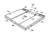
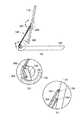
図1〜4を参照すると、電子機器100の斜視図が示されている。ここにおいて、電子機器100は、ヒンジアセンブリ130を介して本体120に枢軸結合されているディスプレイハウジング110と、ディスプレイ支持機構140と、を備える。 1-4, the perspective view of the
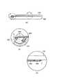
図に示されているように、電子機器100は、第1の閉(「CLOSED」)位置(図1,2)、第2の開(「OPENED」)位置(図3)、および第3の反転(「INVERTED」)位置(図4)にある。これらの位置の各々において、ディスプレイハウジング110の上部または底部は、ディスプレイ支持機構140に対して概して面一である。もちろん、電子機器100は、以下に記載するように、ディスプレイハウジング110の垂直回転に応じた他の位置に配置されてもよい。 As shown, the
本発明の一実施の形態の場合、図1〜4中に示されているように、本体120は、2つの主パネル部、すなわち、フロントパネル部122及びバックパネル部124を備える。これらのパネル部122,124は、電子機器100のハードウェア構成要素および格納されたソフトウェア構成要素を収容するように共に結合されている。これは、これらの構成要素を異物および環境条件から保護する。本発明のこの実施の形態の場合、パネル部122及び124は、硬質プラスチックの如き柔軟でない材質で形成されている。 In the embodiment of the present invention, as shown in FIGS. 1 to 4, the
図示はしていないが、本体120内に、機械ドライブ(駆動装置)または光学ドライブ(駆動装置)を用いてもよいことが意図されている。通常、これらのドライブ(駆動装置)は、本体120の縁部に沿って位置づけられている。 Although not shown, it is contemplated that a mechanical drive (drive device) or an optical drive (drive device) may be used in the
ディスプレイハウジング110は、フラットパネルディスプレイ111、およびフラットパネルディスプレイ111上に表示可能な画像を生成する回路要素を収容する。フラットパネルディスプレイ111の例は、限定または規制されるのではないが、液晶ディスプレイ(LCD)、プラズマディスプレイ、またはこれらと同様のものを含む。 The
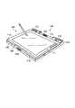
本発明のこの実施の形態の場合、ディスプレイハウジング110は、2つのパネル部、すなわち、フロントディスプレイパネル112及びバックディスプレイパネル114、を備える。図2中に詳細に示されているように、バックディスプレイパネル114は、ディスプレイ支持機構140(図5参照)の第1の部材を完全に収容するような寸法にされている深さを有している凹部領域115を含む。従って、電子機器100が上記閉位置(図1)にあるとき、バックディスプレイパネル114の上面116はディスプレイ支持機構140の上面141とほぼ同一平面になっている。また、バックディスプレイパネル114の凹部領域115が、以下に記載されているように、ディスプレイ支持機構140を形成している部材の厚さの変化を受け入れるよう、1つまたはそれ以上の第2の凹部領域117を備えてもよいことが意図されている。 For this embodiment of the invention, the
図2にさらに示されているように、これらの凹部領域115および/または117は、ディスプレイハウジング110が完全に反転されたとき(例えば、ディスプレイハウジング110のバックパネル114が本体120のフロントパネル部122に近接するよう垂直方向に回転されたとき)、ディスプレイ支持機構140が(フロントパネル部122に一体化されている)キーボード180に、あるいは本体120のフロントパネル部122の上面123に、直接接触するのを協働して防いでいる。本発明のこの実施の形態の場合、ディスプレイハウジング110は、電子機器100が閉位置にあるときの方向から約180°垂直方向に回転されたときに反転される。 As further shown in FIG. 2, these
図1中に示されているように、ヒンジアセンブリ130は、本体120の底縁125およびディスプレイ支持機構140の第1の端部142に結合するために構成されている。本発明の一実施の形態では、ヒンジアセンブリ130は、ディスプレイハウジング110を本体120の上方で選択された回転角度に維持するために、例えば摩擦ヒンジの形式の如きブレーキヒンジとして適合されている。例えば、ヒンジアセンブリ130は、ディスプレイハウジング110を角度Aに維持するように適合されていてよく、この場合「A」は、約30°乃至約150°の間の範囲である(図3)。 As shown in FIG. 1, the
第1のヒンジユニット150は、ディスプレイ支持機構140の第2の端部144に適合されている。本発明の一実施の形態として、第1のヒンジユニット150は、ディスプレイハウジング110のバックディスプレイパネル114の長手方向の中心に略配置されている単一のヒンジまたは複数のヒンジを備える。しかしながら、第1のヒンジユニット150が、該長手方向の中心からずれていてもよいことが意図されている。第1のヒンジユニット150は、ディスプレイハウジング110が、第1のヒンジユニット150によって設定されている水平な回転軸にしたがって、垂直方向に回転可能にしている。第1のヒンジユニット150はさらに、図4中に示されている如くディスプレイハウジング110が反転できるようにしている。 The
図1〜4をなお参照すると、本体120の上縁126上に位置付けられている相補的な留め具162に固定するために、留め具160がディスプレイハウジング110の上縁118に沿って位置付けされている。これらの留め具160,162は、係合されたとき、ディスプレイハウジング110の角回転を防ぐとともに係合が解除されるまで電子機器110を閉位置に維持する。 Still referring to FIGS. 1-4,
デュアルスピーカ170,172が本体120内に一体化されているとともにディスプレイ支持機構140によって分離されている。スピーカ170,172は、ディスプレイハウジング110が下降され電子機器100が閉位置にあるとき、実質的に見えている。
図3中に示されているように、開位置において、電子機器100は、本体120に一体化されているキーボード180にたいするアクセスを使用者に提供する。さらに、電子機器100は、本体120に一体化されている2次入力装置185に対するアクセスを使用者に提供する。2次入力装置185の例は、例えばタッチパッドまたはトラックボールを含んでよい。 As shown in FIG. 3, in the open position,
本発明の一実施の形態の場合、1つまたはそれ以上の溝190および192がフロントパネル部122上に形成されている。各溝190および/または192は、図2中に示されている如くバックディスプレイパネル114上に位置されている1つまたはそれ以上のばね負荷保持フック113を収容する凹部領域191,193を含む。ばね負荷保持フック113は、ディスプレイハウジング110が反転されているときに反動され、そして、従って、ディスプレイハウジング110が反転位置にあるとき(図4)、凹部領域191,193と係合されている。さもなければ、ディスプレイハウジング110がディスプレイ支持機構140に取り付けられたとき(例えば、電子機器100が開位置または閉位置にあるとき)、ばね負荷保持フック113はディスプレイ支持機構140によってディスプレイハウジング110内に押し込まれている。 In one embodiment of the present invention, one or
ディスプレイハウジング110および本体120の異なる領域が、異なる材料で適合されていてもよいことが意図されている。例えば、2次入力装置185を取り囲んでいるフロントパネル部122の一部は、長期間の使用後に損傷するのを改善するために、ステンレス鋼または他の金属組成物により適合されていてもよい。 It is contemplated that different regions of
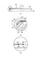
次に図5を参照すると、図1のディスプレイ支持機構140の第1の実施の形態の斜視図が示されている。ディスプレイ支持機構140は、第1の部材200及び第2の部材220を備える。一般に、第1の部材200はヒンジアセンブリ130および第1のヒンジユニット150の両方に結合されている。第2の部材220は、ヒンジアセンブリ130及び、第1のヒンジユニット150からずれている第2のヒンジユニット230に結合されている。これらの結合のうちの少なくともいくつか、あるいは全ては、事実上枢軸的である。 Referring now to FIG. 5, a perspective view of a first embodiment of the
ここにおいては、図6および図7の(a)中に示されているように、ヒンジアセンブリ130はブレーキヒンジである。しかしながら、本発明の一実施の形態としては、ヒンジアセンブリ130は、端部131及び132間に位置されている軸133を伴なった少なくとも2つの端部131,132を備える。本体120または該ケース内の構成要素に強固に固定した場合、端部131、132は軸133の回転をわずかに阻み、それによってブレーキヒンジとして動作するように適合されていてよい。各端部131及び132は、その中を介して相互接続136が道筋立てられる(routed)ようにする開口134及び135を含む。 Here, as shown in FIGS. 6 and 7A, the
一般に、本発明の一実施の形態の場合、軸133は、第1の軸部137と第2の軸部138との間に介在されている第3の軸部139を特徴とする。軸部137及び138は、非円形の断面領域(例えば、平坦な外辺および湾曲された外辺を伴なっている半円形領域)によって構成されている。第3の軸部139は、第1および第2の軸部137及び138の断面領域よりも小さい断面領域を特徴とする。 In general, in the case of an embodiment of the present invention, the
ここにおいて、第1の部材200は軸部137及び138に枢軸結合されており、第2の部材220は第3の軸部139に枢軸結合されている。ヒンジは、この枢軸結合を実現するのに使用されてよい。しかしながら、軸133をどのような形状にしたがって構成してもよいが、このような構成は開口134および/または135を介した相互接続136の為の供給通路を妨げることなく軸133の回転を可能にすべきであることが意図されている。 Here, the
相互接続136を、他の実施の形態によって、本体120とディスプレイハウジング110との間で分けることができることが意図されている。例えば、図7の(b)中に示されているように、相互接続136は、ブレーキヒンジ130の第1の部分の周りに巻くことにより、本体120からディスプレイハウジング110に設けられている。この実施の形態は、図7の(a)の開口134および/または135が設けられていない場合に用いることができる。 It is contemplated that the
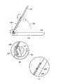
図5に戻って参照すると、第2の部材220は、ヒンジアセンブリ130及び、第1のヒンジユニット150からずれており1つまたはそれ以上のヒンジを備えている第2のヒンジユニット230に枢軸結合されている。この実施の形態の場合、第2のヒンジユニット230は、バックディスプレイパネル114の凹部領域117内に位置決めされている。また、第2の部材220の第1の端部222は、開口134または135を介した供給通路の完全な交差を避けるように、角度Bだけ角度が付けられている。これは、ディスプレイハウジング110が垂直方向に回転されたときに、第2の部材220が、開口134を介して道筋が立てられている相互接続を損傷させるのを防ぐ。角度「B」は、この実施の形態の場合、15°と70°の間の範囲である。 Referring back to FIG. 5, the
本発明の一実施の形態の場合、第1の部材200は、部材200及び220がほぼ同一面になる(即ち、概して同じ平面内にある)ように第2の部材220を収容するような寸法にされている凹部領域205を含む。さらに、凹部領域205は、電子機器100が開位置または閉位置に配置されたときに、第2の部材220を実質的に収容する。この時、第2の部材220の突出部225は、凹部領域205の凹部部分206内に位置されている。さらに、凹部領域205は、電子機器100が反転位置に配置されているとき、第2の部材220を実質的に収容する。この時、第2の部材220の突出部225は、凹部領域205の凹部部分207内に位置されている。 For one embodiment of the present invention, the
第1および第2のヒンジユニット150及び230によって設定されている水平な回転軸に従うディスプレイハウジング110の回転中、第2の部材220は第1の部材200から離れ、そしてもはや該第1の部材200とは同一平面にはない。さらに、本発明の一実施の形態によれば、第2の部材220もまた第1の部材200から斜めに(例えば、非平行に)なる。 During rotation of the
要約すれば、第1の部材200は、ディスプレイハウジング110(または第2の部材220)が第1の位置に配置されているとき、第2の部材220と実質的に同一平面にあるとともに該第2の部材と平行であってよい。この「第1の」位置において、ディスプレイハウジング110の上部または底部のいずれかが、ディスプレイ支持部材140に対して概して面一になるよう位置付けられている(図9の(a)、図10の(a)、図14の(a)および図15の(a)参照)。しかしながら、ディスプレイハウジング110が第2の位置に配置されているとき、第2の部材220は第1の部材200から斜めになって、もはや該第1の部材とは同一平面ではなくなる。一般に、上記第2の位置は、ディスプレイハウジング110がディスプレイ支持部材140から引き離されるとともにヒンジユニット150及び230によって設定されている水平軸周りに回転されたときに、実現される。 In summary, the
具体的には、図11の(a)、図12の(a)、および図13の(a)中に示されているように、第1および第2のヒンジユニット150、230によって設定されている回転軸に沿ったディスプレイハウジング110の初期の時計回りの回転は、最初は第1の部材200と同一平面であった第2の部材220を第1の部材200から遠ざかるよう移動させる。また、第2の部材220は、第1の部材200から斜めになり、それに伴って該第1の部材200とは平行でなくなる。ディスプレイハウジング110の時計回りの引き続く回転は第2の部材220を第1の部材200からさらに離し、第2の部材220が互いに非平行な状態を続ける。一実施の形態においては、所定の距離は1/4インチを越えるが、しかしながら、どのような所定の距離も適応されることができる。 Specifically, it is set by the first and
図13の(a)および図14の(a)中に示されているように、図9の(a)における非回転状態からの概して90°を越える、第1および第2のヒンジユニット150及び230によって設定されている集合的な回転軸に沿ったディスプレイハウジング110のさらなる時計回りの回転は、第1の部材200および第2の部材220の減少された隔離を生じさせる。ディスプレイハウジング110が図15の(a)中に示されているように反転されると、第2の部材220は、図5の第1の部材200の凹部領域205内に再び位置付けされることになる。その結果、第2の部材220は、再び、第1の部材200と同一平面になり、かつ該と平行になる。 As shown in FIGS. 13 (a) and 14 (a), the first and
次に図8を参照すると、ディスプレイ支持機構140の第2の実施の形態の斜視図が示されている。ここにおいて、ディスプレイハウジング110は、第1のヒンジユニット150を介してディスプレイ支持機構140に枢軸結合されたままである。しかしながら、ディスプレイ支持機構140は複数のアームによって構成されている。ここにおいて、第1の部材200は、第1のヒンジユニット150の一端に枢軸結合されている第1のアーム305と、第1のヒンジユニットの他端に枢軸結合されている第2のアーム310と、を備える。第1および第2のアーム305及び310は、第1の軸部137および第2の軸部138に夫々枢軸結合されることができる。第2の部材220は、ヒンジアセンブリ130および第2のヒンジユニット230に枢軸結合されている第3のアーム315を備える。アーム305,310,そして315は、図2の凹部領域115の深さよりも小さい厚さに寸法きめされている。 Referring now to FIG. 8, a perspective view of a second embodiment of the
今度は図9の(a)〜図9の(c)を参照すると、第1および第2の部材200及び220の枢軸結合されている端部の詳細図と共に、図1の電子機器100の断面図が示されている。本発明のこの実施の形態の場合、ディスプレイ支持機構140は、互いに実質的に同一平面であってよい第1の部材200および第2の部材220によって構成されている。ディスプレイハウジング110は、ディスプレイ支持機構140に対して面一になるように位置決めされている。 Referring now to FIGS. 9 (a) -9 (c), a cross-section of the
より具体的には、第1の部材200の第1の端部202は軸133の外側縁部(例えば、軸部138)に枢軸結合されているとともに該外側縁部に概して近接しており、第2の部材220の角度が付けられた第1の端部222は軸133の内側部(例えば、第3の軸部139)に枢軸結合されている。第1の部材200の第2の端部204は第1のヒンジユニット150に結合されており、第2の部材220の第2の端部224は第2のヒンジユニット230に結合されている。従って、電子機器100が閉位置にある間に、第1および第2の部材200及び220の両方が、示されているように互いにほぼ同一平面にあるる。 More specifically, the
また、図9の(b)および図9の(c)中に示されているように、電子機器100が閉位置に配置されているとき、平面Aが平面Bから斜めになり、そして平面Bと平行にならないように方向決めされていることが認識される。平面Aは第1および第2の部材200及び220の端部202及び222における枢軸点を含む。平面Bは、第1および第2の部材200及び220の端部204及び224における枢軸点を含む。 Further, as shown in FIGS. 9B and 9C, when the
図10の(a)〜図10の(c)を参照すると、第1および第2の部材200及び220の枢軸結合されている端部の詳細図と共に、電子機器100の断面図が示されている。本発明のこの実施の形態の場合、ディスプレイハウジング110およびディスプレイ支持機構140は、矢印250により示されているように同時に垂直方向に旋回されている。しかしながら、ディスプレイハウジング110をディスプレイ支持機構140に対して面一に維持するよう、第1および第2のヒンジユニット150及び230によって設定されている水平方向の回転軸周りのいかなる角回転もまだない。その結果、第1および第2の部材200及び220は、図10の(c)中に示されているように、概して同一平面のままである。 Referring to FIGS. 10A to 10C, a cross-sectional view of the
ここにおいては、図10の(b)中に示されているように図9の(b)と比較して、ヒンジアセンブリ130の軸133は、図9の(b)の矢印255により指摘されているように、時計回り方向に90°未満の角度だけ回転している。このような回転は、第1の部材200の第1の端部202および第2の部材220の第1の端部222の対応している動きを引き起こし、開口135を通る相互接続のための供給通路を依然として維持する。 Here, as shown in FIG. 10 (b), compared to FIG. 9 (b), the
次に図11の(a)〜図11の(c)を参照すると、第1および第2の部材200及び220の枢軸結合されている端部の詳細図と共に、電子機器100の断面図が示されている。本発明のこの実施の形態の場合、ディスプレイハウジング110は、矢印260により示されているように、第1のヒンジユニット150および第2のヒンジユニット230によって設定されている軸の周りで反時計回り方向に垂直方向に回転されている。しかしながら、ヒンジアセンブリ130における軸133の回転はない。これは、第1の部材200および第2の部材220をヒンジユニット150及び230に向かい近接して部分的に離間させる。 Next, referring to FIGS. 11A to 11C, a cross-sectional view of the
図12の(a)〜図12の(c)を参照すると、第1および第2の部材200及び220の枢軸結合されている端部の詳細図と共に、電子機器100の断面図が示されている。本発明のこの実施の形態の場合、ディスプレイハウジング110は、矢印265により例示されている反時計周り方向で垂直方向に回転され続ける。このような回転は、図11の(a)〜図11の(c)中に明確にされている位置と比較して、ヒンジアセンブリ130の軸133の反時計周り方向への回転を生じさせる。 12 (a) to 12 (c), a cross-sectional view of the
第2の部材220の角度の付いた第1の端部222のお蔭により、軸133の回転は、第1の部材200を下方にずらし、かつ第2の部材220を上方にずらす。このようなずらしは、第1の部材200と第2の部材220との間の離間をさらに生じさせる。この位置において、電子機器100の第1の部材200および第2の部材220は互いにわずかに斜めになり、開口135を通る供給通路は依然として維持される。 By virtue of the angled
図12(b)および図12(c)中に示されているように、ディスプレイハウジング110が、ここに示されているようにディスプレイ支持機構140から一旦離されそして回転されると、平面Cは平面Dと平行になる。平面Cは第1および第2の部材200及び220の端部202及び222における枢軸点を含み、平面Dは第1および第2の部材200及び220の端部204及び224における枢軸点をそれぞれ含む。 As shown in FIGS. 12 (b) and 12 (c), once the
図13の(a)〜図13の(c)を参照すると、第1および第2の部材200及び220の枢軸結合されている端部の詳細図と共に、電子機器100の断面図が示されている。本発明のこの実施の形態の場合、ディスプレイハウジング110は矢印270により示されているように反時計周り方向に垂直方向に回転され続ける。この位置において、ディスプレイハウジング110は、殆どすでに十分に反転されている。このような回転は、図12の(a)〜図12の(c)中に図示されている位置と比較して、反時計周り方向における軸133のさらなる回転を生じさせる。 Referring to FIGS. 13A to 13C, a cross-sectional view of the
軸133の回転は、第1の部材200を下方へずらし続け、かつ第2の部材220を上方へずらし続ける。このずらしは、第1の部材200および第2の部材220を図12の(a)中に図示されているよりも小さな離間距離で再位置付けする。 The rotation of the
今度は図14の(a)〜図14の(c)を参照すると、第1および第2の部材200及び220の枢軸結合されている端部の詳細図と共に、電子機器100の断面図が示されている。本発明のこの実施の形態の場合、ディスプレイハウジング110は、ほとんど反転されている。従って、ディスプレイハウジング110のバックディスプレイパネルは、ディスプレイ支持機構140に対して面一になっている。 Referring now to FIGS. 14 (a) -14 (c), a cross-sectional view of the
この位置において、ヒンジアセンブリ130の軸133は、図13の(a)〜図13の(c)中に明らかにされている位置と比較して、反時計周り方向にさらに回転されている。軸133の回転は、図9の(a)および図10の(a)中に同様に示されているように、第1の部材200および第2の部材220を互いに略同一平面に再位置付けする。示されているように、相互接続の為に許容されている空間が前に示されているものから減少されているにもかかわらず、開いている供給通路は依然として維持されている。 In this position, the
今度は図15の(a)〜図15の(c)を参照すると、第1および第2の部材200及び220の枢軸結合されている端部の詳細図と共に、図4の電子機器100の断面図が示されている。本発明のこの実施の形態の場合、ディスプレイハウジング110は既に反転されていて、ディスプレイ支持機構140はディスプレイハウジング110と本体120との間に位置付けられている。ディスプレイハウジング110のバックパネル114は、本体120のフロントパネル部122に対して概して面一である。 Referring now to FIGS. 15 (a) -15 (c), a cross-section of
また、図15の(b)および図15の(c)中に示されているように、ディスプレイハウジング110が反転位置に配置されたとき、平面Eは平面Fから斜めになり、かつ平面Fとは平行にならないように方向が決められている。平面Eは第1および第2の部材200及び220の端部202及び222における枢軸点を含む。平面Fは第1および第2の部材200及び220の端部204および224における枢軸点を含む。 Further, as shown in FIGS. 15B and 15C, when the
要約すると、ディスプレイハウジング110がディスプレイ支持機構140から離されているとともにヒンジユニット150及び230によって設定されている1つまたはそれ以上の水平方向の回転軸の周りに回転されたとき、第1および第2の部材200の同じ端部における枢軸点を含めた第1の平面は第1および第2の部材220の他方の端部における枢軸点を含めた第2の平面と平行になる。回転の量は、第1の位置、すなわち、水平方向の回転軸周りのディスプレイハウジング110の角回転を開始する直前のディスプレイハウジング110の位置、から、10°と170°との範囲で変化してもよい。該第1の位置において、ディスプレイハウジング110のバックディスプレイパネルの一部は、ディスプレイ支持機構140に対して概して面一である。 In summary, when the
本発明の特定の実施の形態を記載し、かつ添付図面に示してきたが、そのような実施の形態は、単に例証的なものであり、かつ本発明の様々な実施の形態の広い態様を規制するものではなく、また、種々の他の変更が可能であるため、これらの実施の形態は、図示および記載した特定の構造および配置を限定するものではないことを理解すべきである。 While particular embodiments of the present invention have been described and illustrated in the accompanying drawings, such embodiments are merely illustrative and illustrate the broad aspects of the various embodiments of the present invention. It should be understood that these embodiments are not intended to limit the particular structures and arrangements shown and described, as these are not restrictive and various other modifications are possible.
100…電子機器、110…ディスプレイハウジング、111…フラットパネルディスプレイ、112…フロントディスプレイパネル、113…負荷保持フック、114…バックディスプレイパネル、115,117…凹部領域、116,123,141…上面、118,126…上縁、120…本体、122…フロントパネル部、124…バックパネル部、125…底縁、130…ヒンジアセンブリ、131,132…端部、133…軸、134,135…開口、136…配線、137…第1の軸部、138…第2の軸部、139…第3の軸部、140…ディスプレイ支持機構、142,202,222…第1の端部、144,204,224…第2の端部、150…第1のヒンジユニット、160,162…留め具、170,172…デュアルスピーカ、180…キーボード、185…2次入力装置、190,192…溝、191,193,205…凹部領域、200…第1の部材、206,207…凹部部分、220…第2の部材、225…突出部、230…第2のヒンジユニット、305…第1のアーム、310…第2のアーム、315…第3のアーム、A,B,C,D,E,F…平面 DESCRIPTION OF
Claims (5)
Translated fromJapanese前記本体に結合されているヒンジアセンブリと;
フロントディスプレイパネルとバックディスプレイパネルとによって覆われているフラットパネルディスプレイを備えているディスプレイハウジングと;
第1の枢軸点において前記ヒンジアセンブリと枢軸結合されているとともに第2の枢軸点において前記ディスプレイハウジングと枢軸結合されている第1の部材と、第3の枢軸点において前記ヒンジアセンブリに枢軸結合されているとともに第4の枢軸点において前記ディスプレイハウジングに枢軸結合されている第2の部材と、を備えているディスプレイ支持機構と;
を備えており、
前記ディスプレイハウジングが第1の位置に配置されたとき、前記第1および第3の枢軸点を含んでいる第1の平面が前記第2および第4の枢軸点を含んでいる第2の平面と平行になり、
前記ディスプレイハウジングが第2の位置に配置されたとき、前記第1の平面は前記第2の面と平行でなくなるように方向つけされることを特徴とする電子機器。With the body;
A hinge assembly coupled to the body;
A display housing comprising a flat panel display covered by a front display panel and a back display panel;
A first member pivotally coupled to the hinge assembly at a first pivot point and pivotally coupled to the display housing at a second pivot point; and pivotally coupled to the hinge assembly at a third pivot point. And a second member pivotally coupled to the display housing at a fourth pivot point; and a display support mechanism comprising:
With
A second plane in which the first plane containing the first and third pivot points includes the second and fourth pivot points when the display housing is disposed in the first position; Become parallel,
The electronic apparatus according to claim 1, wherein when the display housing is disposed at the second position, the first plane is oriented so as not to be parallel to the second surface.
Applications Claiming Priority (1)
| Application Number | Priority Date | Filing Date | Title |
|---|---|---|---|
| US10/654,834US6961234B2 (en) | 2003-09-04 | 2003-09-04 | Display support mechanism |
Publications (1)
| Publication Number | Publication Date |
|---|---|
| JP2005092864Atrue JP2005092864A (en) | 2005-04-07 |
Family
ID=34136683
Family Applications (1)
| Application Number | Title | Priority Date | Filing Date |
|---|---|---|---|
| JP2004193617APendingJP2005092864A (en) | 2003-09-04 | 2004-06-30 | Electronics |
Country Status (4)
| Country | Link |
|---|---|
| US (1) | US6961234B2 (en) |
| EP (1) | EP1513047A3 (en) |
| JP (1) | JP2005092864A (en) |
| CN (1) | CN1285021C (en) |
Cited By (6)
| Publication number | Priority date | Publication date | Assignee | Title |
|---|---|---|---|---|
| WO2011037176A1 (en)* | 2009-09-28 | 2011-03-31 | 京セラ株式会社 | Mobile electronic device |
| JP2013073345A (en)* | 2011-09-27 | 2013-04-22 | Toshiba Corp | Electronic apparatus |
| WO2013114503A1 (en)* | 2012-02-03 | 2013-08-08 | ソニー株式会社 | Information terminal device |
| JP2014044460A (en)* | 2012-08-24 | 2014-03-13 | Sony Corp | Information processing apparatus |
| JP2014512043A (en)* | 2011-03-28 | 2014-05-19 | シェル−ライン カンパニー リミテッド | Sliding and tilting tablet computer |
| JP2014232386A (en)* | 2013-05-28 | 2014-12-11 | ソニー株式会社 | Electronic device |
Families Citing this family (33)
| Publication number | Priority date | Publication date | Assignee | Title |
|---|---|---|---|---|
| US7035090B2 (en)* | 2003-09-04 | 2006-04-25 | Kabushiki Kaisha Toshiba | Interlocking mechanism for a display |
| US7206196B2 (en)* | 2003-09-15 | 2007-04-17 | Intel Corporation | Computer system with detachable display |
| US20050156952A1 (en)* | 2004-01-20 | 2005-07-21 | Orner Edward E. | Interactive display systems |
| KR100526617B1 (en)* | 2004-03-12 | 2005-11-08 | 삼성전자주식회사 | Monitor |
| US7184617B2 (en)* | 2004-03-12 | 2007-02-27 | Matsushita Electric Industrial Co., Ltd. | Portable device |
| TWM261726U (en)* | 2004-07-06 | 2005-04-11 | High Tech Comp Corp | Handheld electronic device |
| US7239505B2 (en)* | 2004-10-08 | 2007-07-03 | Microsoft Corporation | Direct hinge for optimizing conversion |
| JP2006157769A (en)* | 2004-12-01 | 2006-06-15 | Nec Access Technica Ltd | Portable terminal |
| US20060256512A1 (en)* | 2005-05-11 | 2006-11-16 | Esther Kang Mi J | Display panel mount for a notebook or tablet computer |
| US20100004124A1 (en)* | 2006-12-05 | 2010-01-07 | David Taft | Systems and methods for delivery of materials for agriculture and aquaculture |
| JP4396726B2 (en)* | 2007-05-23 | 2010-01-13 | ソニー株式会社 | Display device |
| JP2008292691A (en)* | 2007-05-23 | 2008-12-04 | Sony Corp | Display device |
| US9074721B2 (en) | 2010-06-09 | 2015-07-07 | Alex Lau | Support system |
| US9316346B2 (en) | 2010-06-09 | 2016-04-19 | Colebrook Bosson Saunders (Products) Limited | Support system |
| USD684982S1 (en) | 2010-08-11 | 2013-06-25 | Colebrook Bosson Saunders (Products) Limited | Display support with indicator window |
| TWI459886B (en)* | 2011-03-11 | 2014-11-01 | Quanta Comp Inc | Portable electrical device |
| TWI502313B (en)* | 2012-06-08 | 2015-10-01 | Wistron Corp | Support mechanism for supporting a display module on a base and portable electronic device therewith |
| US9715251B2 (en)* | 2012-08-28 | 2017-07-25 | Samsung Electronics Co., Ltd. | Portable device |
| JP2014059397A (en)* | 2012-09-14 | 2014-04-03 | Olympus Imaging Corp | Imaging device |
| JP6155952B2 (en) | 2013-03-26 | 2017-07-05 | ソニー株式会社 | Electronics |
| JP6201508B2 (en)* | 2013-03-26 | 2017-09-27 | ソニー株式会社 | Information processing apparatus and information processing method |
| US9483084B2 (en)* | 2013-09-27 | 2016-11-01 | Intel Corporation | Frictional hinge for electronic devices |
| US9360889B2 (en)* | 2013-12-27 | 2016-06-07 | Intel Corporation | Routing signals via hinge assemblies for mobile computing devices |
| US9256253B2 (en) | 2013-12-28 | 2016-02-09 | Intel Corporation | Clasp assembly and data interconnection for wearable computing devices |
| US9383778B2 (en)* | 2013-12-31 | 2016-07-05 | Google Inc. | Disc style 360 degree hinge for a laptop computer |
| US10133314B2 (en) | 2014-05-26 | 2018-11-20 | Apple Inc. | Portable computing system |
| US10228721B2 (en)* | 2014-05-26 | 2019-03-12 | Apple Inc. | Portable computing system |
| US10317937B2 (en)* | 2014-05-28 | 2019-06-11 | Hewlett-Packard Development Company, L.P. | Computing device with a rotatable display housing |
| US10310564B2 (en) | 2014-06-30 | 2019-06-04 | Hewlett-Packard Development Company, L.P. | Linking mechanism for a computing device with a rotatable display member |
| CN207586791U (en) | 2014-09-30 | 2018-07-06 | 苹果公司 | Portable computing system |
| US10162390B2 (en) | 2015-01-16 | 2018-12-25 | Apple Inc. | Hybrid acoustic EMI foam for use in a personal computer |
| CN108664086B (en)* | 2018-06-29 | 2025-04-22 | 联想(北京)有限公司 | An electronic device |
| US10774981B1 (en)* | 2019-12-06 | 2020-09-15 | Todd McCall | Collapsible support structure for a removable electronic device |
Family Cites Families (29)
| Publication number | Priority date | Publication date | Assignee | Title |
|---|---|---|---|---|
| US5268817A (en)* | 1990-04-27 | 1993-12-07 | Kabushiki Kaisha Toshiba | Portable computer with keyboard and having display with coordinate input tablet rotatably mounted to face either toward or away from keyboard when closed over keyboard |
| JPH0749725A (en) | 1993-08-06 | 1995-02-21 | Sharp Corp | Information processing equipment |
| US6094180A (en)* | 1996-04-05 | 2000-07-25 | Fakespace, Inc. | Gimbal-mounted virtual reality display system |
| JPH1055227A (en) | 1996-08-09 | 1998-02-24 | Sharp Corp | Information processing device |
| US6288891B1 (en)* | 1996-11-21 | 2001-09-11 | Canon Kabushiki Kaisha | Movable display apparatus |
| US6005767A (en)* | 1997-11-14 | 1999-12-21 | Vadem | Portable computer having articulated display |
| US5991150A (en)* | 1997-09-09 | 1999-11-23 | International Business Machines Corporation | Self deploying magnifier for a portable computer display screen |
| US6464195B1 (en)* | 1997-12-04 | 2002-10-15 | Raymond Hildebrandt | Ergonomic mounting for computer screen displays |
| KR100505945B1 (en)* | 1998-03-18 | 2005-10-19 | 삼성전자주식회사 | Monitor having a control function for display angle and height |
| US6282082B1 (en)* | 1998-07-31 | 2001-08-28 | Qubit, Llc | Case for a modular tablet computer system |
| US6483445B1 (en)* | 1998-12-21 | 2002-11-19 | Intel Corporation | Electronic device with hidden keyboard |
| JP2000228128A (en) | 1999-02-08 | 2000-08-15 | Matsushita Graphic Communication Systems Inc | Communication terminal device |
| GB2348459B (en)* | 1999-03-27 | 2003-03-19 | Ibm | Lid restraint for portable computer |
| US6196850B1 (en)* | 2000-02-10 | 2001-03-06 | International Business Machines Corporation | Rotatable docking station for an electronic device |
| US6430038B1 (en)* | 2000-04-18 | 2002-08-06 | Hewlett-Packard Company | Computer with articulated mechanism |
| US6437973B1 (en)* | 2000-04-18 | 2002-08-20 | Hewlett-Packard Company | Modular mechanism for movable display |
| JP2002023650A (en)* | 2000-06-14 | 2002-01-23 | Internatl Business Mach Corp <Ibm> | Portable computer device |
| US6396687B1 (en)* | 2000-10-13 | 2002-05-28 | Dell Products, L.P. | Rotating portable computer docking station |
| JP3607608B2 (en)* | 2000-12-19 | 2005-01-05 | 株式会社日立製作所 | Liquid cooling system for notebook computers |
| JP2002222026A (en) | 2001-01-26 | 2002-08-09 | Nec Yonezawa Ltd | Portable information processor |
| US6717798B2 (en)* | 2001-03-22 | 2004-04-06 | Intel Corporation | Docking digital picture displays |
| US6402109B1 (en)* | 2001-05-16 | 2002-06-11 | Chief Manufacturing, Inc. | Self-balancing mounting system for a flat panel display |
| US6480373B1 (en)* | 2001-07-24 | 2002-11-12 | Compaq Information Technologies Group, L.P. | Multifunctional foldable computer |
| US6873521B2 (en)* | 2001-07-24 | 2005-03-29 | Hewlett-Packard Development Company, L.P. | Multiple environment foldable computer |
| JP2003044169A (en) | 2001-07-31 | 2003-02-14 | Casio Comput Co Ltd | Electronics |
| JP2003223238A (en)* | 2002-01-28 | 2003-08-08 | Internatl Business Mach Corp <Ibm> | Computer device, monitor unit and support structure of unit facing user |
| US6856506B2 (en)* | 2002-06-19 | 2005-02-15 | Motion Computing | Tablet computing device with three-dimensional docking support |
| US6788530B2 (en)* | 2002-09-24 | 2004-09-07 | International Business Machines Corporation | User friendly computer equipment, monitor unit, and monitor unit setting base |
| US7035090B2 (en)* | 2003-09-04 | 2006-04-25 | Kabushiki Kaisha Toshiba | Interlocking mechanism for a display |
- 2003
- 2003-09-04USUS10/654,834patent/US6961234B2/ennot_activeExpired - Fee Related
- 2004
- 2004-06-30JPJP2004193617Apatent/JP2005092864A/enactivePending
- 2004-08-27EPEP04020384Apatent/EP1513047A3/ennot_activeWithdrawn
- 2004-09-03CNCN200410068608.4Apatent/CN1285021C/ennot_activeExpired - Fee Related
Cited By (7)
| Publication number | Priority date | Publication date | Assignee | Title |
|---|---|---|---|---|
| WO2011037176A1 (en)* | 2009-09-28 | 2011-03-31 | 京セラ株式会社 | Mobile electronic device |
| US8885331B2 (en) | 2009-09-28 | 2014-11-11 | Kyocera Corporation | Portable electronic apparatus |
| JP2014512043A (en)* | 2011-03-28 | 2014-05-19 | シェル−ライン カンパニー リミテッド | Sliding and tilting tablet computer |
| JP2013073345A (en)* | 2011-09-27 | 2013-04-22 | Toshiba Corp | Electronic apparatus |
| WO2013114503A1 (en)* | 2012-02-03 | 2013-08-08 | ソニー株式会社 | Information terminal device |
| JP2014044460A (en)* | 2012-08-24 | 2014-03-13 | Sony Corp | Information processing apparatus |
| JP2014232386A (en)* | 2013-05-28 | 2014-12-11 | ソニー株式会社 | Electronic device |
Also Published As
| Publication number | Publication date |
|---|---|
| EP1513047A2 (en) | 2005-03-09 |
| CN1285021C (en) | 2006-11-15 |
| EP1513047A3 (en) | 2010-04-28 |
| CN1591275A (en) | 2005-03-09 |
| US6961234B2 (en) | 2005-11-01 |
| US20050052834A1 (en) | 2005-03-10 |
Similar Documents
| Publication | Publication Date | Title |
|---|---|---|
| JP2005092864A (en) | Electronics | |
| CN1322393C (en) | Electronic device | |
| US9715251B2 (en) | Portable device | |
| US6771494B2 (en) | Portable computer usable in laptop and tablet configurations | |
| US8908364B2 (en) | Portable computer | |
| US6829140B2 (en) | Portable computer usable in laptop and tablet configurations | |
| JP2005149469A (en) | Electronics | |
| JP6201508B2 (en) | Information processing apparatus and information processing method | |
| CN101669080B (en) | Adjustable display | |
| US9632529B2 (en) | Portable computer | |
| US20040203994A1 (en) | Portable computer having adjustable display | |
| US8917500B2 (en) | Portable computer | |
| JP2005085260A (en) | Electronics | |
| US8896558B2 (en) | Portable computer with adjustable touch screen display | |
| JP2006252546A (en) | Switchable computer system | |
| US9317071B2 (en) | Electronic device and hinge module thereof | |
| TW201506590A (en) | Adjustable display housing assembly | |
| US9876521B2 (en) | Sliding stand assembly | |
| US20200133336A1 (en) | Electronic device with dual display | |
| TW201322891A (en) | Portable computer | |
| CN113711159B (en) | Information handling system dual pivot hinge signal path | |
| TWI498491B (en) | Opening-closing apparatus and hinge device thereof | |
| JP6206144B2 (en) | Folding-type article opening / closing device and electronic apparatus equipped with the opening / closing device | |
| TWI756589B (en) | Electronic devices with hinge assemblies | |
| CN100428110C (en) | portable computer |