JP2005091447A - 3D display device - Google Patents
3D display deviceDownload PDFInfo
- Publication number
- JP2005091447A JP2005091447AJP2003321277AJP2003321277AJP2005091447AJP 2005091447 AJP2005091447 AJP 2005091447AJP 2003321277 AJP2003321277 AJP 2003321277AJP 2003321277 AJP2003321277 AJP 2003321277AJP 2005091447 AJP2005091447 AJP 2005091447A
- Authority
- JP
- Japan
- Prior art keywords
- lobe
- display device
- stereoscopic display
- stereoscopic
- control means
- Prior art date
- Legal status (The legal status is an assumption and is not a legal conclusion. Google has not performed a legal analysis and makes no representation as to the accuracy of the status listed.)
- Withdrawn
Links
Images


Landscapes
- Liquid Crystal Display Device Control (AREA)
- Testing, Inspecting, Measuring Of Stereoscopic Televisions And Televisions (AREA)
- Control Of Indicators Other Than Cathode Ray Tubes (AREA)
Abstract
Description
Translated fromJapanese本発明は、複数の視差画像を観察者に表示することで立体表示を行う立体表示装置、特に3視差以上の視差画像を表示する多眼式の立体表示装置に関する。 The present invention relates to a stereoscopic display device that performs stereoscopic display by displaying a plurality of parallax images to an observer, and more particularly to a multi-view stereoscopic display device that displays parallax images of three or more parallaxes.
(1)従来の2眼式立体表示手段の説明:
左右2枚の視差画像を観察者の眼に各々表示する、所謂、2眼式立体表示装置は構成が簡素なため、広く用いられてきた。直視型の2眼式立体表示装置はパララックスバリア方式とレンチキュラ方式が代表的で広く知られている。(1) Description of conventional binocular stereoscopic display means:
A so-called binocular stereoscopic display device that displays two parallax images on the left and right sides of the observer's eyes has been widely used because of its simple configuration. As the direct-view type binocular stereoscopic display device, a parallax barrier method and a lenticular method are typical and widely known.
パララックスバリア方式については、非特許文献1(S.H.Kaplan, “Theory of
Parallax Barriers", J.SMPTE,Vol. 59,No.7,pp.11−21(1952))に開示されている。この方式によれば、複数視点からの複数視差画像のうち、少なくとも左右視差画像を交互に配列されたストライプ画像を、この画像から所定の距離だけ離れた位置に設けられた所定の開口部を有するスリット(パララックスバリアと呼ばれる)を介して、左右それぞれの眼でそれぞれの眼に対応した視差画像を観察することにより立体視を行うことができる。Regarding the parallax barrier method, Non-Patent Document 1 (SHKaplan, “Theory of
Parallax Barriers ", J. SMPTE, Vol. 59, No. 7, pp. 11-21 (1952). According to this method, at least left-right parallax among a plurality of parallax images from a plurality of viewpoints. The stripe images in which the images are alternately arranged are separated by the left and right eyes through slits (called parallax barriers) having predetermined openings provided at positions separated from the images by a predetermined distance. Stereoscopic viewing can be performed by observing a parallax image corresponding to the eye.
レンチキュラ方式は、ディスプレイの前面にかまぼこ状のレンズを多数並べたレンチキュラを設け、空間的に左右の眼に入る画像を分離してユーザに立体像を観察させる。
(2)2D/3D混在表示の説明:
2次元画像(一視点画像)表示装置との両立を達成するために、パララックスバリアを透過型液晶表示装置等により電子的に発生させ、バリアパターンの形状や位置等を電子的に可変制御するようにした立体表示装置が、特許文献1及び特許文献2に開示されている。In the lenticular method, a lenticular in which a number of kamaboko-shaped lenses are arranged on the front surface of a display is provided, and a spatial image is separated into left and right eyes to allow a user to observe a stereoscopic image.
(2) Explanation of 2D / 3D mixed display:
In order to achieve compatibility with a two-dimensional image (one viewpoint image) display device, a parallax barrier is electronically generated by a transmissive liquid crystal display device or the like, and the shape and position of the barrier pattern are variably controlled electronically. Such a stereoscopic display device is disclosed in Patent Document 1 and
図14は特許文献1に開示されている立体画像表示装置の基本構成図である。 FIG. 14 is a basic configuration diagram of a stereoscopic image display device disclosed in Patent Document 1.
この立体画像表示装置は、画像表示を行う透過型液晶表示装置901と、これに厚さdのスペーサー902を介して配置される透過型液晶表示素子を具備する。透過型液晶表示装置901には2方向又は多方向から撮像した視差画像を縦ストライプ画像として表示する。そして、電子式パララックスバリア903にはXYアドレスをマイクロコンピュータ904等の制御部によって指定することにより、バリア面上の任意の位置にパララックスバリアパターンを形成し、前記パララックスバリア方式の原理に従って立体視を可能とする。 This stereoscopic image display device includes a transmissive liquid crystal display device 901 that displays an image, and a transmissive liquid crystal display element that is disposed on the transmissive liquid crystal display device 901 via a
又、図15は特許文献2に開示されている液晶パネルディスプレイと電子式パララックスバリアによって構成された立体画像表示装置の表示部の構成図であり、2枚の液晶層915,925をそれぞれ2枚の偏光板911,918及び912,928で挟んだ構成になっている。この装置において、2次元画像表示を行う際には、電子式パララックスバリアパターンの表示を停止し、電子式バリア903の画像表示領域の全域に亘って無色透明な状態にすることで、2次元表示との両立性を実現している。 FIG. 15 is a configuration diagram of a display unit of a stereoscopic image display device configured by a liquid crystal panel display and an electronic parallax barrier disclosed in
又、特許文献2には、図16に示すように透過型液晶表示素子から成る電子式パララックスバリア903の一部領域にのみバリア・ストライプのパターンを発生させることができる構成とし、3次元画像と2次元画像とを同一面内で混在表示することを可能とした例が開示されている。
(3)多眼式の立体表示装置の説明:
上述のように左右2枚の視差画像を用いる2眼式立体表示装置では立体に観察できる立体観察領域が狭い。この短所を克服するため、3つ以上の視差画像を観察者に表示する多眼式立体表示装置の試みがなされてきた。Further, in
(3) Description of multi-view stereoscopic display device:
As described above, in the binocular stereoscopic display device using two right and left parallax images, the stereoscopic observation region that can be stereoscopically observed is narrow. In order to overcome this disadvantage, attempts have been made for a multi-view stereoscopic display device that displays three or more parallax images to an observer.
複数台の投射型表示装置からレンチキュラスクリーンに視差画像を投影する方式等が代表的である。又、液晶表示装置やプラズマディスプレイ等のフラットディスプレイとパララックスバリアやレンチキュラを組み合わせて多眼表示する立体表示装置も従来から知られている。一般にレンチキュラやパララックスバリアを用いて多眼表示する立体表示装置は水平方向のみ解像度が劣化し、水平方向と垂直方向の解像度バランスが悪くなる。この水平解像度のみの劣化を垂直方向に分散して解像劣化を平均化した例が、特許文献6や特許文献3にて提案されている。
(4)多眼式のメインローブ及びサイドローブの説明:
特許文献7の図17では3眼式、図18では4眼式の例が述べられている。特許文献7の図17において、立体的に観察できる領域は図中のA,B及びCである。又、図に示すように、その領域が周期的に繰り返すので隣のA,B及びCの領域でも観察できる。中央で観察可能な領域(A,B及びC)をメインローブ、その横にある観察可能領域をサイドローブと呼ぶ。A method of projecting parallax images from a plurality of projection display devices onto a lenticular screen is representative. In addition, a stereoscopic display device that performs multi-view display by combining a flat display such as a liquid crystal display device or a plasma display with a parallax barrier or lenticular is also conventionally known. In general, a stereoscopic display device that performs multi-view display using a lenticular or parallax barrier deteriorates the resolution only in the horizontal direction, and the resolution balance in the horizontal and vertical directions is deteriorated.
(4) Description of multi-lens main lobe and side lobe:
FIG. 17 of Patent Document 7 describes an example of a trinocular system and FIG. In FIG. 17 of Patent Document 7, regions that can be observed stereoscopically are A, B, and C in the figure. Further, as shown in the figure, since the region repeats periodically, it can be observed in the adjacent regions A, B, and C. The area (A, B, and C) that can be observed in the center is called a main lobe, and the observable area next to the main lobe is called a side lobe.
メインローブは図中の光学フィルタの開口(レンズ)機能部分に対応する液晶パネルの画像を分離するが、サイドローブでは隣の開口を透過して視差画像を表示する。メインローブとサイドローブの境界部分、例えば特許文献7の図17では左目にA領域、右目C領域の際は逆立体視の状態となり、正常な立体視はできない。特許文献7の図18は4眼の例であり、A,B,C及びDが1つのローブであり、中央にメインローブ、横にサイドローブが繰り返される。3眼よりも4眼の方が逆立体視に対して正立体視領域の割合が増えて、観察し易い表示となる。このように眼数が多いほど、観察し易くなるが、反面、解像度の高い表示パネルが必要となる。
(5)サイドローブ利用した公知例1:
特許文献4の実施例4(図34〜図36)には2つの空間変調素子を用いて、サイドローブを利用して表示する方式が開示されている。この例では開口制御用の空間変調素子(SLM2)の開口位置の制御と視差画像を表示する空間変調素子(SLM1)の表示画像の制御を行うことによって、広い観察領域を確保している。
(6)サイドローブ利用した公知例2:
特許文献5には、シャッタアレイと同期し、サイドローブを利用する立体表示技術が開示されている。The main lobe separates the image of the liquid crystal panel corresponding to the aperture (lens) functional portion of the optical filter in the figure, but the side lobe transmits the adjacent aperture and displays the parallax image. In the boundary portion between the main lobe and the side lobe, for example, in FIG. 17 of Patent Document 7, when the left eye is in the A region and the right eye C region, the reverse stereoscopic viewing is performed, and normal stereoscopic viewing is not possible. FIG. 18 of Patent Document 7 is an example of four eyes. A, B, C, and D are one lobe, and a main lobe is repeated in the center and side lobes are repeated. The ratio of the normal stereoscopic vision area increases with respect to the reverse stereoscopic vision in the four eyes rather than the three eyes, and the display becomes easy to observe. As the number of eyes increases, the observation becomes easier, but a display panel with high resolution is required.
(5) Known example 1 using side lobes 1:
Example 4 (FIGS. 34 to 36) of
(6) Known example 2 using side lobes:
Patent Document 5 discloses a stereoscopic display technique that uses side lobes in synchronization with a shutter array.
(1)従来の2眼式では観察領域が狭く、観察位置によっては逆立体視になる。
(2)上記従来例の多眼式では表示パネルの解像度は表示眼数に反比例するため、連続した立体視領域を広げるために眼数を多くすると、それに応じて高解像度の表示パネルが必要となる。
(3)特許文献4に記載されている方法では、シリンドリカルレンズアレイのピッチが大きいと、そのピッチの画像ムラが観察されて視認性の悪い画像となる。そのため、ピッチを小さくする必要がある。特許文献4の実施例4の形態では、シリンドリカルレンズアレイのレンズの数に比例して高速表示切り替えをする必要があり、非現実的であった。又、1つのシリンドリカルレンズに対応した開口しか空いていないため、画像が暗くなる問題があった。
(4)特許文献5では、開口が周期的に発生するシャッタアレイと二次元表示面の組み合わせで構成されるため、画像が所定の開口以外から観察されない条件を満たすためには、シャッタアレイと表示面の間隔やシャッタアレイのピッチ及び視差画像のピッチ等の制約が大きく、設計自由度が狭い。
(5)特許文献4や特許文献5のように時分割を利用する立体表示装置では、表示パネルに高速な表示速度が要求され、構成上の選択肢が狭い。
(6)後述の実施の形態1に示す多眼式立体表示装置では、2D/3D切り替え及び2D/3D混在表示が実現できない。(1) In the conventional binocular system, the observation area is narrow, and depending on the observation position, reverse stereoscopic viewing is performed.
(2) In the conventional multi-lens system, the resolution of the display panel is inversely proportional to the number of display eyes. Therefore, if the number of eyes is increased in order to expand the continuous stereoscopic viewing area, a high-resolution display panel is required accordingly. Become.
(3) In the method described in
(4) In Patent Document 5, since a combination of a shutter array in which apertures are periodically generated and a two-dimensional display surface is used, in order to satisfy a condition that an image is not observed from other than a predetermined aperture, a shutter array and a display are used. Restrictions such as the space between the surfaces, the pitch of the shutter array and the pitch of the parallax images are large, and the degree of freedom in design is narrow.
(5) In a stereoscopic display device using time division as in
(6) 2D / 3D switching and 2D / 3D mixed display cannot be realized in the multi-view stereoscopic display device described in Embodiment 1 described later.
本発明は上記問題に鑑みてなされたもので、その目的とする処は、立体表示領域を拡大することができる立体表示装置を提供することにある。 The present invention has been made in view of the above problems, and an object thereof is to provide a stereoscopic display device capable of enlarging a stereoscopic display area.
上記目的を達成するため、本発明は、立体観察領域にメインローブとサイドローブを交互に表示する多眼立体表示手段と、前記メインローブ或はサイドローブの発生を順次切り替えて繰り返し制御するローブ制御手段と、前記ローブ制御手段によって発生したメインローブ或はサイドローブに応じた視差画像を表示する視差画像表示手段と、前記ローブ制御手段と視差画像手段のタイミングを図る同期手段を含んで立体表示装置を構成したことを特徴とする。 To achieve the above object, the present invention provides multi-view stereoscopic display means for alternately displaying a main lobe and a side lobe in a stereoscopic observation area, and a lobe control for repeatedly controlling the generation of the main lobe or the side lobe by sequentially switching. 3D display device comprising: means, a parallax image display means for displaying a parallax image corresponding to a main lobe or a side lobe generated by the lobe control means, and a synchronization means for timing the lobe control means and the parallax image means It is characterized by comprising.
又、本発明は、立体観察領域にメインローブとサイドローブを交互に表示する多眼立体表示手段と、観察者の視点位置を検出する視点位置検出手段と、前記視点検出手段が得た視点位置に応じてローブを発生させるローブ位置制御手段と、前記視点検出手段或は前記ローブ位置制御手段に応じた視差画像を表示する視差画像表示手段を含んで立体表示装置を構成したことを特徴とする。 The present invention also provides multi-view stereoscopic display means for alternately displaying main lobes and side lobes in the stereoscopic observation area, viewpoint position detection means for detecting the viewpoint position of the observer, and viewpoint positions obtained by the viewpoint detection means. The stereoscopic display device is configured to include a lobe position control unit that generates a lobe according to the position and a parallax image display unit that displays a parallax image according to the viewpoint detection unit or the lobe position control unit. .
本発明によれば、メインローブとサイドローブが発生し、複数の視差画像を表示する立体表示手段に前記メインローブ或はサイドローブを制御する手段を設けることによって、立体表示領域を拡大することができ、観察者一人の場合でも、視点追従が構成でき、表示パネルの表示速度に依存することなく、立体表示領域が拡大できる。 According to the present invention, a main lobe and side lobes are generated, and a stereoscopic display area can be enlarged by providing means for controlling the main lobe or side lobe in the stereoscopic display means for displaying a plurality of parallax images. Even when only one observer is present, the viewpoint tracking can be configured, and the stereoscopic display area can be enlarged without depending on the display speed of the display panel.
2次元表示と3次元表示が制御できる手段を設けることにより、2D/3D切り替え表示と2D/3D混在表示が可能となる。 By providing means capable of controlling two-dimensional display and three-dimensional display, 2D / 3D switching display and 2D / 3D mixed display are possible.
以下、添付の図面を参照して本発明の実施の形態を説明する。 Hereinafter, embodiments of the present invention will be described with reference to the accompanying drawings.
<実施の形態1>
図1〜図3を用いてサイドローブ利用の基本原理である実施の形態1を説明する。本実施の形態では、立体表示光学系をパララックスバリア方式として説明するが、観察領域にメインローブとサイドローブが交互に表示されるレンチキュラ等の他の方式でも成り立つ。
(1)実施の形態1の全体構成:
図1に本実施の形態で多眼3次元表示を行うための光学系の斜視図を示す。<Embodiment 1>
Embodiment 1 which is a basic principle of using side lobes will be described with reference to FIGS. In the present embodiment, the stereoscopic display optical system is described as a parallax barrier system, but other systems such as a lenticular display in which main lobes and side lobes are alternately displayed in the observation region are also valid.
(1) Overall configuration of the first embodiment:
FIG. 1 shows a perspective view of an optical system for performing multi-view three-dimensional display in the present embodiment.
101は視差画像を光学的に指向性を持たせるためのパララックスバリアである。102は表示パネルで、液晶表示装置やプラズマディスプレイ等の所謂、フラットパネルディスプレイによって構成され、コンピュータ等の映像信号により所定の視差画像を表示する。50Rと50Lは観察者の右目と左目を現す。103はローブ制御部材で、液晶表示パネル等の空間変調素子で構成され、光の透過と遮光を電子的に制御し、立体表示のローブ発生を制御する。 Reference numeral 101 denotes a parallax barrier for optically directing the parallax image. Reference numeral 102 denotes a so-called flat panel display such as a liquid crystal display device or a plasma display, and displays a predetermined parallax image by a video signal from a computer or the like. 50R and 50L represent the right and left eyes of the observer.
図2に本実施の形態のシステム構成を示す。 FIG. 2 shows the system configuration of the present embodiment.
110はローブ制御部材103を所定の位置に開口発生させるローブ制御駆動部、120は表示パネル102の画像表示を制御する画像表示系、130はローブ制御駆動部と画像表示系のタイミングを取るためのローブ同期部である。ローブ同期部130は、表示パネル102の表示タイミングとローブ制御部材103の開口発生位置のタイミングを取るものであり、画像表示制御部或はローブ制御駆動部110の中に機能が含まれても問題ない。
(2)ローブ制御と表示画像の動作説明:
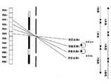
図3(1)〜(3)は本発明の動作を説明する動作図であり、メインローブ及び左右サイドローブの合計3つを利用し、4眼式のパララックス光学系で視差画像1〜視差画像12までの12眼の視差画像を表示することが可能である。110 is a lobe control driving unit that generates an opening of the
(2) Explanation of lobe control and display image operation:
3 (1) to 3 (3) are operation diagrams for explaining the operation of the present invention, using a total of three main lobes and left and right side lobes, and a parallax image 1 to parallax with a four-lens parallax optical system. It is possible to display 12-eye parallax images up to image 12.
図3の表示パネル102の視差画素ピッチとパララックスバリア101の開口ピッチは、従来のパララックスバリア方式やレンチキュラ方式で知られているように幾何学的な関係で導かれる。図中のように視差画像のピッチPA、パララックスバリアのピッチPB、眼数をNd(本実施の形態では、N=4)以下の関係になる。 The parallax pixel pitch of the display panel 102 in FIG. 3 and the opening pitch of the parallax barrier 101 are derived in a geometrical relationship as is known in the conventional parallax barrier method and lenticular method. As shown in the figure, the parallax image pitch PA, the parallax barrier pitch PB, and the number of eyes are Nd (in this embodiment, N = 4) or less.
PA×Nd>PB
更に、ローブ制御部材の開口ピッチをPCとおくと以下の関係になる。PA × Nd> PB
Further, when the opening pitch of the lobe control member is set to PC, the following relationship is established.
PA×Nd>PC>PB
図3ではパララックスバリアと表示パネルの間にローブ制御部材が設けられているが、ローブ制御部材をパララックスバリアと観察者の間に設けても良く、この場合は以下の関係となる。PA × Nd>PC> PB
In FIG. 3, the lobe control member is provided between the parallax barrier and the display panel. However, the lobe control member may be provided between the parallax barrier and the observer. In this case, the following relationship is established.
PA×Nd>PB>PC
ローブ制御部材は、所定の観察領域で1つのローブのみ表示するように構成される。パララックスバリア等の光学構成により、ローブ制御部材の仕様は幾何学的に求めることができる。PA × Nd>PB> PC
The lobe control member is configured to display only one lobe in a predetermined observation area. The specification of the lobe control member can be obtained geometrically by an optical configuration such as a parallax barrier.
図3(1)はメインローブのみ、即ち、視差画像5から視差画像8を表示するものである。図3(1)ではローブ制御部材の作用によってサイドローブが発生しないように表示パネルからの画像光を制御する。この視差画像5から視差画像8に対応する画像を表示パネルに表示する。 FIG. 3A shows only the main lobe, that is, the
図3(2)では、左側のサイドローブのみ、即ち視差画像1から視差画像4を表示するようにローブ制御部材を制御する。同時に表示パネルに対応した視差画像を表示する。同様に図3(3)は右側のサイドローブのみ、即ち視差画像9から視差画像12を表示するようにローブ制御部材と表示パネルを制御する。図3(1)〜(3)で説明した動作を観察者の残像時間内に行えば、観察者には視差画像1〜視差画像12の画像を観察することができる。
(3)表示光学系の眼数、使用ローブ数及び観察できる眼数の関係:
1つのローブ内で提示できる表示光学系の眼数をNd、表示に使用するローブの数をNr、観察者に表示できる眼数をNoとおけば、これらの関係は以下のように単純なものになる。In FIG. 3B, the lobe control member is controlled so that only the left side lobe, that is, the parallax images 1 to 4 are displayed. At the same time, a parallax image corresponding to the display panel is displayed. Similarly, in FIG. 3C, the lobe control member and the display panel are controlled so that only the right side lobe, that is, the parallax image 12 to the parallax image 12 is displayed. If the operations described in FIGS. 3A to 3 are performed within the observer's afterimage time, the observer can observe the parallax images 1 to 12.
(3) Relationship between the number of eyes of the display optical system, the number of lobes used, and the number of eyes that can be observed:
If the number of eyes of the display optical system that can be presented in one lobe is Nd, the number of lobes used for display is Nr, and the number of eyes that can be displayed to the observer is No, these relationships are as follows: become.
No=Nd×Nr
又、上述の図2で説明した内容では、メインローブと2つのサイドローブの構成で、Nr=3である。このようにNrが奇数のときにはメインローブとサイドローブの区別ができる。しかし、Nrが偶数のときにはメインローブとサイドローブの区別がつかないが、図2のシーケンスが偶数回数になるだけで問題ない。No = Nd × Nr
Further, in the content described with reference to FIG. 2 above, Nr = 3 in the configuration of the main lobe and the two side lobes. Thus, when Nr is an odd number, the main lobe and the side lobe can be distinguished. However, when Nr is an even number, the main lobe and the side lobe cannot be distinguished, but there is no problem if the sequence of FIG.
更にNrが奇数ならば、そのメインローブの中心位置を立体表示装置の表示部の略中心位置にする。Nrが偶数ならば、ローブとローブの境界位置を立体表示装置の表示部の略中心位置にする。
(4)ローブ制御手段の他の方法:
上記では、ローブ制御手段を電子的に制御可能な空間変調素子として説明したが、開口がパターニングされた板ガラス状の開口マスク板を機械的に移動させても同等の効果がある。Further, if Nr is an odd number, the center position of the main lobe is set to the approximate center position of the display unit of the stereoscopic display device. If Nr is even, the boundary position between the lobes is set to the approximate center position of the display unit of the stereoscopic display device.
(4) Other methods of lobe control means:
In the above description, the lobe control means is described as an electronically controllable spatial modulation element. However, the same effect can be obtained by mechanically moving a plate-glass-shaped aperture mask plate with patterned openings.
以上、実施の形態1で説明したようにサイドローブを利用して表示することにより、連続して立体観察できる領域、即ち、メインローブ領域を大幅に広げることが可能である。 As described above, the display using the side lobes as described in the first embodiment makes it possible to greatly expand the region where the stereoscopic observation can be performed continuously, that is, the main lobe region.
<実施の形態2>
図4〜図13を用いて視点追従に関する実施の形態2について説明する。尚、図中の番号で実施の形態1と同じものは同様の機能を果たす。
(1)実施の形態1の多眼式に視点追従を付加した場合のメリット:
2眼式の立体表示装置では、観察者の視点位置を検出し、その視点位置に立体視領域を追従することで実用上の立体視領域を拡大している。この場合、2人以上の観察者に立体視領域を追従させることは不可能であり、1人用の立体表示装置となってしまう。しかしながら、パーソナルコンピュータ等のように、通常は1人で観察するものが多く、1人用のデメリット以上に立体視領域が広がるメリットの方が大きい場合も多い。<
A second embodiment regarding viewpoint tracking will be described with reference to FIGS. The same reference numerals as those in the first embodiment perform the same functions.
(1) Advantages of adding viewpoint tracking to the multi-view system of the first embodiment:
In the binocular stereoscopic display device, the viewpoint position of the observer is detected, and the stereoscopic vision area is expanded by following the stereoscopic vision area to the viewpoint position. In this case, it is impossible for two or more observers to follow the stereoscopic vision region, resulting in a stereoscopic display device for one person. However, there are many things that are usually observed by one person, such as a personal computer, etc., and there are many cases where the merit of expanding the stereoscopic viewing area is larger than the disadvantage of one person.
実施の形態1のような多眼式の立体表示装置に視点追従機能を付加したときのメリットは2つある。1つは表示パネルやローブ制御部材の駆動周波数が低く抑えられる。もう1つは、2眼式に比べて視点検出と追従の精度が甘くても良い。
(2)視点検出・追従のシステムの説明:
図4は実施の形態2の視点検出・追従システムを説明するシステム構成図である。There are two merits when the viewpoint tracking function is added to the multi-view stereoscopic display device as in the first embodiment. One is that the drive frequency of the display panel and lobe control member can be kept low. The other is that the accuracy of viewpoint detection and tracking may be less than that of the twin-lens system.
(2) Explanation of viewpoint detection / follow-up system:
FIG. 4 is a system configuration diagram illustrating the viewpoint detection / follow-up system according to the second embodiment.
図中の201は観察者の視点位置を検出するための視点検出部である。視点検出の手段はビデオカメラで撮影した画像を画像処理によって観察者を抽出するものや、赤外線の投受光によって検出するもの等、様々な手段が既に開示されている。本実施の形態も公知の検出技術を利用することができる。202は追従制御部で視点検出部201からの視点位置に応じて、ローブ制御駆動部203と画像表示制御部204に司令を出す。ローブ制御駆動部203は観察者の視点位置に応じて開口位置を制御し、画像表示制御部では観察位置に応じた視差画像を表示する。シーケンシャルに制御していた実施の形態1とは、これらの点で異なる。
(3)視点追従の動作説明:
図5〜図7は本発明の動作を説明する動作図である。図5は観察者が略中央(領域1)にいる場合、図6は観察者が左側(領域2)にいる場合、図7は観察者が右側(領域3)にいる場合である。201 in the figure is a viewpoint detection unit for detecting the viewpoint position of the observer. Various means have already been disclosed as viewpoint detection means, such as extracting an observer by image processing of an image taken by a video camera, and detecting by infrared light projection and reception. This embodiment can also use a known detection technique. A
(3) Explanation of viewpoint tracking operation:
5 to 7 are operation diagrams for explaining the operation of the present invention. FIG. 5 shows a case where the observer is substantially in the center (area 1), FIG. 6 shows a case where the observer is on the left side (area 2), and FIG. 7 shows a case where the observer is on the right side (area 3).
図8〜図11は上述の動作を行っても、観察者の片目のみ視差画像が表示され、正常な立体視の状態に無い場合の説明図である。 FIGS. 8 to 11 are explanatory diagrams in the case where the parallax image is displayed only on one eye of the observer and the state is not in a normal stereoscopic view even when the above-described operation is performed.
図12と図13は上述の図8〜図11の問題点を解決するものである。図中の領域4〜6のように所定量シフトした制御領域を設けることでローブ間にオーバーラップが生じる。そのシフトした制御領域に対応してローブ制御部材のローブ発生と視差画像の描画を行えば良い。この所定シフト量は視差画像間のピッチの整数倍となる。例えば、図12のローブは「視差画像6,5,4,3」のローブ、図13は「視差画像10,9,8,7」のローブのように構成する。このように図12と図13の状態を発生することで、観察者の片目のみに視差画像を表示することはない。 FIGS. 12 and 13 solve the problems of FIGS. 8 to 11 described above. By providing a control region shifted by a predetermined amount as in
以上、実施の形態2で説明したように、1人の観察者の立体視領域を表示デバイスの表示速度に関係なく拡大できる。 As described above, as described in
<実施の形態3>
以下に、2次元表示に関して説明する。
(1)立体表示装置における2次元表示の一般的な説明:
コンピュータシステムやテレビジョンシステムでは、従来のデータやソースを使用するために2次元表示の要求がある。立体表示装置で行う2次元表示としては、2D/3D切り替え表示と2D/3D混在表示がある。2D/3D切り替え表示は、立体表示装置の表示画面を2次元表示或は3次元表示に切り替えるもので、2次元表示のときは通常の2次元専用と同様の使用ができる。2D/3D混在表示は、立体表示装置の表示画面の一部が3次元表示、他が2次元表示されるものである。<
Hereinafter, the two-dimensional display will be described.
(1) General description of two-dimensional display in a stereoscopic display device:
In computer systems and television systems, there is a need for two-dimensional display in order to use conventional data and sources. Two-dimensional display performed by the stereoscopic display device includes 2D / 3D switching display and 2D / 3D mixed display. The 2D / 3D switching display switches the display screen of the stereoscopic display device to a two-dimensional display or a three-dimensional display, and can be used in the same manner as a normal two-dimensional display in the case of a two-dimensional display. In the 2D / 3D mixed display, a part of the display screen of the stereoscopic display device is three-dimensionally displayed and the other is two-dimensionally displayed.
本発明の実施形態で2次元表示するには以下の方法がある。
(2)表示パネルの表示画像のみで制御:
2D/3D切り替え表示する場合には、表示する視差画像を全て同じ視差画像にすれば2次元表示なる。又、3次元表示を行いたい部分のみに視差を表示すれば、2D/3D混在表示となる。
(3)パララックスバリアを液晶で構成:
パララックスバリアを液晶表示装置等で構成し、電子的に発生制御ができるように構成すれば、多眼立体表示の有効と無効が制御できる。2D/3D切り替え表示する場合には、パララックスバリアとローブ制御部材を透過になるように制御する。又、3次元表示を行いたい部分のみにパララックスバリアとローブ制御部材の機能を電子的に発生させれば、2D/3D混在表示となる。
(4)拡散板を挿入:
視差画像の光学的な指向性を打ち消すための拡散版を挿入する。又、この拡散板は電気的に拡散或は透過制御できるものでも良い。There are the following methods for two-dimensional display in the embodiment of the present invention.
(2) Control only with display image on display panel:
In the case of 2D / 3D switching display, if all the parallax images to be displayed are the same parallax image, the display is two-dimensional. Further, if parallax is displayed only on a portion where three-dimensional display is desired, 2D / 3D mixed display is obtained.
(3) The parallax barrier is composed of liquid crystals:
If the parallax barrier is configured by a liquid crystal display device or the like and can be controlled electronically, the effectiveness and ineffectiveness of multi-view stereoscopic display can be controlled. When the 2D / 3D switching display is performed, the parallax barrier and the lobe control member are controlled to be transparent. Further, if the functions of the parallax barrier and the lobe control member are electronically generated only in the portion where the three-dimensional display is desired, 2D / 3D mixed display is obtained.
(4) Insert diffusion plate:
A diffusion plate is inserted to cancel the optical directivity of the parallax image. The diffusion plate may be one that can be electrically diffused or permeated.
以上、実施の形態3で説明したように2D/3D切り替え表示と2D/3D混在表示が可能となり、ユーザに使い勝手の良いディスプレイが提供できる。 As described above, the 2D / 3D switching display and the 2D / 3D mixed display are possible as described in
本発明は、複数の視差画像を観察者に表示することで立体表示を行う立体表示装置、特に3視差以上の視差画像を表示する多眼式の立体表示装置に対して適用可能である。 The present invention is applicable to a stereoscopic display device that performs stereoscopic display by displaying a plurality of parallax images to an observer, and particularly to a multi-view stereoscopic display device that displays parallax images of three or more parallaxes.
101 パララックスバリア
102 表示パネル
103 ローブ制御部材
110 ローブ制御駆動部
120 画像表示系
130 ローブ同期部
201 視点検出部
202 追従制御部
203 ローブ制御駆動部Reference Signs List 101 parallax barrier 102
Claims (16)
Translated fromJapaneseNo=Nd×Nr
の関係を満足することを特徴とする請求項1記載の立体表示装置。The number of eyes that can be displayed in one lobe of the main lobe or side lobe of the multi-view display means is Nd, the number of lobes that are sequentially used for switching display by the lobe control means is Nr, and the number of eyes that can be displayed to the observer. When you say No
No = Nd × Nr
The stereoscopic display device according to claim 1, wherein the following relationship is satisfied.
Priority Applications (1)
| Application Number | Priority Date | Filing Date | Title |
|---|---|---|---|
| JP2003321277AJP2005091447A (en) | 2003-09-12 | 2003-09-12 | 3D display device |
Applications Claiming Priority (1)
| Application Number | Priority Date | Filing Date | Title |
|---|---|---|---|
| JP2003321277AJP2005091447A (en) | 2003-09-12 | 2003-09-12 | 3D display device |
Publications (1)
| Publication Number | Publication Date |
|---|---|
| JP2005091447Atrue JP2005091447A (en) | 2005-04-07 |
Family
ID=34453013
Family Applications (1)
| Application Number | Title | Priority Date | Filing Date |
|---|---|---|---|
| JP2003321277AWithdrawnJP2005091447A (en) | 2003-09-12 | 2003-09-12 | 3D display device |
Country Status (1)
| Country | Link |
|---|---|
| JP (1) | JP2005091447A (en) |
Cited By (10)
| Publication number | Priority date | Publication date | Assignee | Title |
|---|---|---|---|---|
| JP2008541165A (en)* | 2005-05-09 | 2008-11-20 | シリコンファイル・テクノロジーズ・インコーポレイテッド | 3D image display device using flat panel display |
| JP2010501083A (en)* | 2006-08-17 | 2010-01-14 | コーニンクレッカ フィリップス エレクトロニクス エヌ ヴィ | Display device |
| JP2011081272A (en)* | 2009-10-08 | 2011-04-21 | Nikon Corp | Image display device and image display method |
| WO2011132422A1 (en)* | 2010-04-21 | 2011-10-27 | パナソニック株式会社 | Three-dimensional video display device and three-dimensional video display method |
| CN102547347A (en)* | 2010-12-28 | 2012-07-04 | 索尼公司 | Three-dimensional image display apparatus |
| JP2012215670A (en)* | 2011-03-31 | 2012-11-08 | Nippon Telegr & Teleph Corp <Ntt> | Naked-eye stereoscopic image display device and method |
| JP2014123130A (en)* | 2013-12-27 | 2014-07-03 | Japan Display Inc | Display device and electronic apparatus |
| US9081196B2 (en) | 2011-07-01 | 2015-07-14 | Japan Display Inc. | Display apparatus |
| US9826222B2 (en) | 2013-09-26 | 2017-11-21 | Nlt Technologies, Ltd. | Stereoscopic image display device, terminal device, stereoscopic image display method, and program thereof |
| CN115685581A (en)* | 2021-07-29 | 2023-02-03 | 京东方科技集团股份有限公司 | A 3D display device and design method |
- 2003
- 2003-09-12JPJP2003321277Apatent/JP2005091447A/ennot_activeWithdrawn
Cited By (14)
| Publication number | Priority date | Publication date | Assignee | Title |
|---|---|---|---|---|
| JP2008541165A (en)* | 2005-05-09 | 2008-11-20 | シリコンファイル・テクノロジーズ・インコーポレイテッド | 3D image display device using flat panel display |
| JP2010501083A (en)* | 2006-08-17 | 2010-01-14 | コーニンクレッカ フィリップス エレクトロニクス エヌ ヴィ | Display device |
| JP2011081272A (en)* | 2009-10-08 | 2011-04-21 | Nikon Corp | Image display device and image display method |
| JP5631329B2 (en)* | 2010-04-21 | 2014-11-26 | パナソニック インテレクチュアル プロパティ コーポレーション オブアメリカPanasonic Intellectual Property Corporation of America | 3D image display apparatus and 3D image display method |
| WO2011132422A1 (en)* | 2010-04-21 | 2011-10-27 | パナソニック株式会社 | Three-dimensional video display device and three-dimensional video display method |
| CN102449534A (en)* | 2010-04-21 | 2012-05-09 | 松下电器产业株式会社 | Three-dimensional video display device and three-dimensional video display method |
| US9215452B2 (en) | 2010-04-21 | 2015-12-15 | Panasonic Intellectual Property Corporation Of America | Stereoscopic video display apparatus and stereoscopic video display method |
| CN102547347A (en)* | 2010-12-28 | 2012-07-04 | 索尼公司 | Three-dimensional image display apparatus |
| JP2012215670A (en)* | 2011-03-31 | 2012-11-08 | Nippon Telegr & Teleph Corp <Ntt> | Naked-eye stereoscopic image display device and method |
| US9081196B2 (en) | 2011-07-01 | 2015-07-14 | Japan Display Inc. | Display apparatus |
| US9826222B2 (en) | 2013-09-26 | 2017-11-21 | Nlt Technologies, Ltd. | Stereoscopic image display device, terminal device, stereoscopic image display method, and program thereof |
| US10567741B2 (en) | 2013-09-26 | 2020-02-18 | Tianma Microelectronics Co., Ltd. | Stereoscopic image display device, terminal device, stereoscopic image display method, and program thereof |
| JP2014123130A (en)* | 2013-12-27 | 2014-07-03 | Japan Display Inc | Display device and electronic apparatus |
| CN115685581A (en)* | 2021-07-29 | 2023-02-03 | 京东方科技集团股份有限公司 | A 3D display device and design method |
Similar Documents
| Publication | Publication Date | Title |
|---|---|---|
| US7468838B2 (en) | Stereoscopic display for switching between 2D/3D images | |
| JP4925702B2 (en) | Stereoscopic video display device for 2D / 3D video compatibility using a polarizing grating screen | |
| JP3966830B2 (en) | 3D display device | |
| CN1893674B (en) | 2D/3D Switchable Stereoscopic Display Provides Full Parallax Images | |
| JP2891177B2 (en) | 3D display device | |
| KR101680771B1 (en) | Three-dimensional image display apparatus and method | |
| JP2846856B2 (en) | 3D image display device | |
| JP2002250895A (en) | Stereoscopic image display method and stereoscopic image display device using the same | |
| JP5107564B2 (en) | Image display device | |
| JPH05122733A (en) | 3D image display device | |
| KR20050115942A (en) | Autostereoscopic display | |
| WO2008032943A1 (en) | Multi-view autostereoscopic display with improved resolution | |
| JP2007156390A (en) | 2D and 3D video selectable display device | |
| JP4546505B2 (en) | Spatial image projection apparatus and method | |
| KR20000002236A (en) | Cubic and multi-visual point 3-dimensional image display device | |
| Dodgson | Autostereo displays: 3D without glasses | |
| JP2005091447A (en) | 3D display device | |
| JP3583936B2 (en) | 3D image display without glasses | |
| JP2005157033A (en) | 3D display device | |
| JP2008541165A (en) | 3D image display device using flat panel display | |
| JPH08327948A (en) | Stereoscopic image display method and stereoscopic image display device | |
| WO2004046788A1 (en) | Light source device for image display device | |
| JP2004282217A (en) | Multiple-lens stereoscopic video image display apparatus | |
| KR101911776B1 (en) | Three-dimensional displaying device and method thereof | |
| Minami et al. | Portrait and landscape mode convertible stereoscopic display using parallax barrier |
Legal Events
| Date | Code | Title | Description |
|---|---|---|---|
| RD01 | Notification of change of attorney | Free format text:JAPANESE INTERMEDIATE CODE: A7421 Effective date:20060201 | |
| A300 | Withdrawal of application because of no request for examination | Free format text:JAPANESE INTERMEDIATE CODE: A300 Effective date:20061205 |