Movatterモバイル変換


[0]ホーム

URL:


JP2005087803A - Reactor - Google Patents

Reactor
Download PDF

Info

Publication number
JP2005087803A
JP2005087803AJP2003321812AJP2003321812AJP2005087803AJP 2005087803 AJP2005087803 AJP 2005087803AJP 2003321812 AJP2003321812 AJP 2003321812AJP 2003321812 AJP2003321812 AJP 2003321812AJP 2005087803 AJP2005087803 AJP 2005087803A
Authority
JP
Japan
Prior art keywords
catalyst
film
substrate
internal space
reactor
Prior art date
Legal status (The legal status is an assumption and is not a legal conclusion. Google has not performed a legal analysis and makes no representation as to the accuracy of the status listed.)
Granted
Application number
JP2003321812A
Other languages
Japanese (ja)
Other versions
JP4961657B2 (en
Inventor
Tadao Yamamoto
忠夫 山本
Current Assignee (The listed assignees may be inaccurate. Google has not performed a legal analysis and makes no representation or warranty as to the accuracy of the list.)
Casio Computer Co Ltd
Original Assignee
Casio Computer Co Ltd
Priority date (The priority date is an assumption and is not a legal conclusion. Google has not performed a legal analysis and makes no representation as to the accuracy of the date listed.)
Filing date
Publication date
Application filed by Casio Computer Co LtdfiledCriticalCasio Computer Co Ltd
Priority to JP2003321812ApriorityCriticalpatent/JP4961657B2/en
Publication of JP2005087803ApublicationCriticalpatent/JP2005087803A/en
Application grantedgrantedCritical
Publication of JP4961657B2publicationCriticalpatent/JP4961657B2/en
Anticipated expirationlegal-statusCritical
Expired - Fee Relatedlegal-statusCriticalCurrent

Links

Images

Classifications

Landscapes

Abstract

Translated fromJapanese

【課題】 触媒が所望の温度に上昇するまでの時間を短縮することができる触媒反応器を提供すること。
【解決手段】 第一基板54には凹部56aが形成され、第一基板54を第二基板55に接合することによって凹部56aが蓋されて、内部空間としてのチャンバー56を有した反応容器本体50が形成される。チャンバー56の平面視形状は長方形を呈しており、チャンバー56の立体形状は薄型の直方体状である。凹部56aの底面には電熱膜51が成膜され、電熱膜51には触媒膜59が積層されている。
【選択図】図1
PROBLEM TO BE SOLVED: To provide a catalytic reactor capable of shortening the time until a catalyst rises to a desired temperature.
A first substrate 54 is formed with a recess 56a. The first substrate 54 is joined to a second substrate 55 to cover the recess 56a, and a reaction vessel main body 50 having a chamber 56 as an internal space. Is formed. The planar view shape of the chamber 56 is rectangular, and the three-dimensional shape of the chamber 56 is a thin rectangular parallelepiped shape. An electrothermal film 51 is formed on the bottom surface of the recess 56 a, and a catalyst film 59 is laminated on the electrothermal film 51.
[Selection] Figure 1

Description

Translated fromJapanese

本発明は、反応容器本体に形成された内部空間で反応を行う反応器に関する。  The present invention relates to a reactor for performing a reaction in an internal space formed in a reaction vessel main body.

近年では、高いエネルギー利用効率を実現できる燃料電池についての研究・開発が盛んにおこなわれている。燃料電池は、燃料と大気中の酸素とを電気化学的に反応させて化学エネルギーから電気エネルギーを直接取り出すものであり、将来性に富む有望な電池であると位置付けられている。燃料電池に用いる燃料としては水素が挙げられるが、常温で気体であることによる取り扱い・貯蔵に問題がある。そこで、アルコール類及びガソリンといった液体燃料を用いれば液体燃料を貯蔵するためのシステムが比較的小型になるが、液体燃料と水蒸気を高温に加熱して反応させることによって発電に必要な水素を生成する改質装置が必要である。また、燃料改質型の燃料電池を小型の電子機器の電源として用いる場合には、燃料電池だけでなく改質装置も小型化する必要がある。  In recent years, research and development have been actively conducted on fuel cells that can achieve high energy use efficiency. BACKGROUND ART A fuel cell is a promising battery that is promising and promising because it directly extracts electric energy from chemical energy by electrochemically reacting fuel and oxygen in the atmosphere. The fuel used in the fuel cell includes hydrogen, but there is a problem in handling and storage due to being a gas at room temperature. Therefore, if liquid fuels such as alcohols and gasoline are used, the system for storing the liquid fuel becomes relatively small, but the hydrogen necessary for power generation is generated by heating and reacting the liquid fuel and water vapor to a high temperature. A reformer is required. When a fuel reforming fuel cell is used as a power source for a small electronic device, it is necessary to downsize not only the fuel cell but also the reforming device.

一方、複数の基板を接合してなる小型のケミカルマイクロリアクタを用いることによって微量の化学反応を行うことが特許文献1に記載されている。特許文献1に記載されたマイクロリアクタについて簡単に説明すると、まず一方の面に流路となる溝が形成されたポリスチレン製の第一の基板を準備し、この溝に蓋をするように第二の基板を第一の基板に紫外線硬化樹脂で接着することによって、これら二枚の基板の接合部に流路を形成している。
特開2002−102681号公報
On the other hand,Patent Document 1 describes that a small amount of chemical reaction is performed by using a small chemical microreactor formed by bonding a plurality of substrates. The microreactor described inPatent Document 1 will be briefly described. First, a first substrate made of polystyrene in which a groove serving as a flow path is formed on one surface is prepared, and a second substrate is covered so as to cover this groove. By adhering the substrate to the first substrate with an ultraviolet curable resin, a flow path is formed at the joint between these two substrates.
JP 2002-102681 A

ところで、ケミカルマイクロリアクタの流路に触媒を設ければ触媒反応器が提供され、化学燃料と水の混合気を流路に流せば、化学燃料と水が触媒反応によって水素に改質されるようになる。触媒反応が常温で起こりにくいため、ケミカルマイクロリアクタを加熱する必要がある。ケミカルマイクロリアクタを加熱する方法は特許文献1に記載されているが、その加熱方法は加熱した金属をケミカルリアクタの外面に接触させるだけである。しかし、触媒がケミカルマイクロリアクタの内側の流路に設けられており、加熱した金属をケミカルリアクタの外面に接触させて触媒を加熱しているため、金属からの熱がケミカルリアクタのポリスチレン等の部材を伝搬することによって触媒に到達して触媒が所望の温度に上昇するまでには長時間を要する。  By the way, if a catalyst is provided in the flow path of the chemical microreactor, a catalytic reactor is provided, and if a mixture of chemical fuel and water flows through the flow path, the chemical fuel and water are reformed to hydrogen by the catalytic reaction. Become. Since the catalytic reaction hardly occurs at room temperature, it is necessary to heat the chemical microreactor. A method of heating the chemical microreactor is described inPatent Document 1, but the heating method is merely bringing the heated metal into contact with the outer surface of the chemical reactor. However, the catalyst is provided in the flow path inside the chemical microreactor, and the heated metal is brought into contact with the outer surface of the chemical reactor to heat the catalyst. It takes a long time for the catalyst to reach the catalyst by propagation and rise to the desired temperature.

そこで、本発明は、上記のような問題点を解決しようとしてなされたものであり、反応に要する温度に上昇するまでの時間を短縮することができる反応器を提供することを目的とする。  Therefore, the present invention has been made to solve the above-described problems, and an object of the present invention is to provide a reactor capable of shortening the time required to increase the temperature required for the reaction.

以上の課題を解決するために、請求項1に記載の発明の反応器は、反応物が供給される内部空間を形成した反応容器本体と、前記内部空間の壁面に成膜された電熱膜と、前記電熱膜に積層された触媒膜と、を具備する。  In order to solve the above problems, the reactor according to the first aspect of the present invention includes a reaction vessel body that forms an internal space to which a reactant is supplied, an electrothermal film formed on a wall surface of the internal space, And a catalyst film laminated on the electrothermal film.

請求項1に記載の発明では、電熱膜に電気エネルギーが供給されると、電熱膜が発熱し、電熱膜で発した熱が反応器全体に伝導し、内部空間に供給された反応物には触媒膜によって触媒反応が生じる。この電熱膜に触媒膜が積層されているので、触媒膜に熱伝導しやすくなる。  In the first aspect of the present invention, when electric energy is supplied to the electrothermal film, the electrothermal film generates heat, heat generated by the electrothermal film is conducted to the entire reactor, and the reactant supplied to the internal space includes A catalytic reaction is caused by the catalyst membrane. Since the catalyst film is laminated on the electrothermal film, heat conduction to the catalyst film is facilitated.

また、請求項2に記載の発明は、請求項1に記載の反応器であって、前記触媒膜の熱伝導率が前記反応容器本体の熱伝導率よりも高いことを特徴とする。  The invention according toclaim 2 is the reactor according toclaim 1, characterized in that the thermal conductivity of the catalyst film is higher than the thermal conductivity of the reaction vessel main body.

また、請求項2に記載の発明では、反応容器本体の熱伝導率よりも触媒膜の熱伝導率が高いため、電熱膜で発した熱が反応容器本体よりも触媒膜に伝導しやすい。  In the invention according toclaim 2, since the thermal conductivity of the catalyst film is higher than the thermal conductivity of the reaction vessel body, the heat generated by the electrothermal film is more easily conducted to the catalyst membrane than the reaction vessel body.

また、請求項3に記載の発明は、請求項1又は2に記載の反応器であって、前記内部空間が六面体状の空間であることを特徴とする。  The invention described inclaim 3 is the reactor according toclaim 1 or 2, wherein the internal space is a hexahedral space.

請求項3に記載の発明では、内部空間が六面体状の空間であるため、反応容器本体の一部が内部空間を突出していない。つまり、内部空間が仕切られていない。  In the invention described inclaim 3, since the internal space is a hexahedral space, a part of the reaction vessel main body does not protrude from the internal space. That is, the internal space is not partitioned.

また、請求項4に記載の発明は、請求項1又は2に記載の反応器であって、前記内部空間が流路状の空間であり、その流路の深さをdchaとし、前記触媒膜の膜厚をdcatとした場合、次式(C)を満たすことを特徴とする。

Figure 2005087803
The invention according toclaim 4 is the reactor according toclaim 1 or 2, wherein the internal space is a flow path-like space, the depth of the flow path is dcha , and the catalyst When the film thickness is dcat , the following formula (C) is satisfied.
Figure 2005087803

また、請求項5に記載の発明は、請求項1から4の何れか一項に記載の反応器であって、前記反応物がメタノールと水との混合気であり、前記触媒膜がメタノールと水を水素と二酸化炭素に改質する性質を有することを特徴とする。  The invention according toclaim 5 is the reactor according to any one ofclaims 1 to 4, wherein the reactant is a mixture of methanol and water, and the catalyst membrane is methanol and It has the property of reforming water into hydrogen and carbon dioxide.

また、請求項6に記載の発明は、請求項5に記載の反応器であって、前記触媒膜には、Cu/Zn系触媒が含まれていることを特徴とする。  The invention according toclaim 6 is the reactor according toclaim 5, wherein the catalyst film contains a Cu / Zn-based catalyst.

請求項6に記載の発明では、Cu/Zn系触媒がメタノールと水を水素と二酸化炭素に改質する性質を有する。  In the invention described inclaim 6, the Cu / Zn-based catalyst has a property of reforming methanol and water into hydrogen and carbon dioxide.

請求項7に記載の発明の反応器は、
反応物が供給される内部空間を形成した反応容器本体を具備し、
前記内部空間が流路状の空間であり、前記内部空間の深さ、長さをそれぞれdcha、Lchaとし、前記内部空間を流れる流体の平均流速、有効拡散係数をそれぞれv、Dmとした場合、次式(A)を満たすことを特徴とする。

Figure 2005087803
The reactor of the invention described inclaim 7 comprises:
Comprising a reaction vessel body having an internal space to which reactants are supplied;
The internal space is a channel-like space, the depth and length of the internal space are dcha and Lcha , respectively, and the average flow velocity and effective diffusion coefficient of the fluid flowing through the internal space are v and Dm , respectively. In this case, the following formula (A) is satisfied.
Figure 2005087803

請求項8に記載の発明の反応器は、
反応物が供給される内部空間面に露出された触媒膜が形成された反応容器本体を具備し、
前記内部空間が流路状の空間であり、前記触媒膜の厚さ、前記内部空間の長さをそれぞれdcha、Lchaとし、前記内部空間を流れる流体の平均流速、有効拡散係数をそれぞれv、DeAとした場合、次式(B)を満たすことを特徴とする。

Figure 2005087803
The reactor of the invention described inclaim 8 is:
Comprising a reaction vessel main body formed with a catalyst film exposed on the inner space to which the reactant is supplied;
The internal space is a channel-like space, and the thickness of the catalyst membrane and the length of the internal space are dcha and Lcha , respectively, and the average flow velocity and effective diffusion coefficient of the fluid flowing through the internal space are v ,DeA , the following formula (B) is satisfied.
Figure 2005087803

請求項1に記載の発明によれば、電熱膜で発した熱が触媒膜に伝導しやすいため、電熱膜で加熱を開始してから触媒膜が所望の温度にまで上昇するのに要する時間を短縮することができ、反応物の触媒反応が効率よく起こるまでの時間も短縮することができる。  According to the first aspect of the present invention, since the heat generated by the electrothermal film is easily conducted to the catalyst film, the time required for the catalyst film to rise to a desired temperature after starting heating with the electrothermal film is reduced. The time until the catalytic reaction of the reactant occurs efficiently can also be shortened.

請求項2に記載の発明によれば、電熱膜で発熱した熱が反応容器本体よりも触媒膜に伝導しやすいため、電熱膜で加熱を開始してから触媒膜が所望の温度にまで上昇するのに要する時間を短縮することができる。更に、電熱膜で発した熱が反応容器本体の加熱よりも触媒膜の加熱に効率よく用いられ、電熱膜の省エネルギーを図ることができる。  According to the second aspect of the present invention, since the heat generated by the electrothermal film is more easily conducted to the catalyst film than the reaction vessel body, the catalyst film rises to a desired temperature after heating is started by the electrothermal film. The time required for this can be shortened. Furthermore, the heat generated by the electrothermal film is used more efficiently for heating the catalyst film than for heating the reaction vessel main body, and energy saving of the electrothermal film can be achieved.

請求項3に記載の発明によれば、反応容器本体の一部が内部空間を突出していないため、内部空間で生じる圧力損失が小さく、反応物を内部空間に供給して生成物を内部空間から排出するために要する負荷が軽減される。また、反応容器本体の一部が内部空間に突出していないため、反応容器本体の熱容量が小さく、電熱膜で発した熱が触媒膜の加熱に効率よく用いられる。  According to the invention described inclaim 3, since a part of the reaction vessel main body does not protrude from the internal space, the pressure loss generated in the internal space is small, and the reaction product is supplied to the internal space and the product is discharged from the internal space. The load required for discharging is reduced. Further, since a part of the reaction vessel main body does not protrude into the internal space, the heat capacity of the reaction vessel main body is small, and the heat generated by the electrothermal film is efficiently used for heating the catalyst film.

請求項4に記載の発明によれば、式(C)を満たすことによって、触媒膜の性能を最大限に触媒反応に用いることができる。  According to the invention described inclaim 4, by satisfying the formula (C), the performance of the catalyst film can be maximized for the catalytic reaction.

請求項5に記載の発明によれば、メタノールから水素を得るための改質反応器として本発明の触媒反応器を用いることができる。  According to the invention described inclaim 5, the catalytic reactor of the present invention can be used as a reforming reactor for obtaining hydrogen from methanol.

請求項6に記載の発明によれば、Cu/Zn系触媒によってメタノールと水から水素と二酸化炭素が生成されるので、請求項5に記載の発明と同様の効果を奏する。  According to the invention described inclaim 6, since hydrogen and carbon dioxide are generated from methanol and water by the Cu / Zn-based catalyst, the same effect as that of the invention described inclaim 5 is achieved.

請求項7に記載の発明によれば、式(A)を満たすことによって、流体が内部空間に流入してから流出するまでの間に内部空間を定義づける反応容器本体の壁(又は溝)に接触するように拡散できるので、壁から伝わる熱を流体に伝搬することができ、流体が反応を促進することが可能となる。  According to the seventh aspect of the present invention, by satisfying the formula (A), the wall (or groove) of the reaction vessel main body defining the internal space from when the fluid flows into the internal space until it flows out. Since it can diffuse to contact, heat transmitted from the wall can be propagated to the fluid, and the fluid can promote the reaction.

請求項8に記載の発明によれば、式(B)を満たすことによって、流体が内部空間に流入してから流出するまでの間に内部空間内の触媒膜中を十分に接触しながら拡散できるので、流体が触媒による反応を十分促進することができる。  According to the eighth aspect of the present invention, by satisfying the formula (B), the fluid can be diffused while sufficiently contacting the catalyst film in the internal space between the time when the fluid flows into the internal space and the time when the fluid flows out. Therefore, the fluid can sufficiently promote the reaction by the catalyst.

以下に、本発明を実施するための最良の形態について図面を用いて説明する。但し、以下に述べる実施形態には、本発明を実施するために技術的に好ましい種々の限定が付されているが、発明の範囲を以下の実施形態及び図示例に限定するものではない。  The best mode for carrying out the present invention will be described below with reference to the drawings. However, although various technically preferable limitations for implementing the present invention are given to the embodiments described below, the scope of the invention is not limited to the following embodiments and illustrated examples.

図1は、本発明を適用した反応器を組み込んだ燃料電池式発電システム1を一部破断して示した斜視図である。  FIG. 1 is a perspective view of a fuel cellpower generation system 1 incorporating a reactor to which the present invention is incorporated, with a part thereof broken away.

図1に示すように、燃料電池式発電システム1は、反応物としての燃料9を貯蔵する燃料貯蔵モジュール2と、本発明の反応器を適用した改質反応器42、水性シフト反応器43及び選択酸化反応器44等を有した小型改質装置40を内蔵するとともに燃料貯蔵モジュール2に貯蔵された燃料9を用いて発電を行う発電モジュール3と、を具備している。  As shown in FIG. 1, a fuel cellpower generation system 1 includes afuel storage module 2 that storesfuel 9 as a reactant, a reformingreactor 42 to which a reactor of the present invention is applied, anaqueous shift reactor 43, and Thepower generation module 3 includes asmall reformer 40 having aselective oxidation reactor 44 and the like, and generates power using thefuel 9 stored in thefuel storage module 2.

燃料貯蔵モジュール2は略円筒状の筐体4を有しており、この筐体4が発電モジュール3に対して着脱自在に取り付けられるようになっている。筐体4の頭頂部には円形の貫通孔5が形成されており、筐体4の外周側には、発電モジュール3で生成された副生成物の水を流通させるための第一排水管6が形成されている。燃料貯蔵モジュール2の底部には、排水用の水を貯留する排水容器7(図2に図示)が配設されており、この排水容器7に上記第一排水管6が接続されている。  Thefuel storage module 2 has a substantiallycylindrical casing 4, and thecasing 4 is detachably attached to thepower generation module 3. A circular throughhole 5 is formed at the top of thecasing 4, and afirst drain pipe 6 for circulating the by-product water generated by thepower generation module 3 is provided on the outer peripheral side of thecasing 4. Is formed. A drainage container 7 (shown in FIG. 2) for storing drainage water is disposed at the bottom of thefuel storage module 2, and thefirst drainage pipe 6 is connected to thedrainage container 7.

筐体4の内部には燃料タンク8が収納されており、燃料タンク8の外周面の一部が筐体4から露出している。燃料タンク8の内部には液体の燃料9が貯蔵されている。燃料タンク8は、内部空間を有した透明又は半透明な円柱状の部材であって、ポリエチレン、ポリプロピレン、ポリカーボネート、アクリル等の材料から形成されている。燃料タンク8の一部が露出しており、燃料タンク8が透明又は半透明であるため、燃料タンク8を通じて内部の燃料9の有無及び残量を容易に確認できるようになっている。  Afuel tank 8 is housed inside thehousing 4, and a part of the outer peripheral surface of thefuel tank 8 is exposed from thehousing 4.Liquid fuel 9 is stored inside thefuel tank 8. Thefuel tank 8 is a transparent or translucent columnar member having an internal space, and is formed of a material such as polyethylene, polypropylene, polycarbonate, acrylic, or the like. Since part of thefuel tank 8 is exposed and thefuel tank 8 is transparent or translucent, the presence / absence and the remaining amount of theinternal fuel 9 can be easily confirmed through thefuel tank 8.

燃料9は、水素元素と炭素元素を含む液状の化学燃料と水との混合液であり、化学燃料としてはメタノール,エタノール等のアルコール類やガソリンといった化合物が適用可能である。本実施形態では、燃料9としてメタノールと水とを等モルで均一に混合した混合液を用いている。  Thefuel 9 is a liquid mixture of a liquid chemical fuel containing hydrogen and carbon elements and water. As the chemical fuel, alcohols such as methanol and ethanol, and compounds such as gasoline are applicable. In the present embodiment, a mixed liquid in which methanol and water are uniformly mixed in an equimolar amount is used as thefuel 9.

燃料タンク8の頭頂部には、燃料9を発電モジュール3に供給するための供給口10が突出して筐体4の貫通孔5にまで挿入されるように配設されており、供給口10の内部には、供給口10全体を閉塞する閉塞膜11が配設されている。燃料タンク8の内部には、図1において上下方向に延在して供給口10に挿入された供給管12が配設されている。この供給管12は、燃料タンク8の底部から供給口10内の閉塞膜11のすぐ下方にまで延在している。供給口10が閉塞膜11で閉塞されることによって、燃料タンク8から外部に燃料9が漏出することが防止されている。  Asupply port 10 for supplying thefuel 9 to thepower generation module 3 protrudes from the top of thefuel tank 8 and is inserted into the throughhole 5 of thehousing 4. Inside, a blockingfilm 11 that blocks theentire supply port 10 is disposed. Inside thefuel tank 8, asupply pipe 12 extending in the vertical direction in FIG. 1 and inserted into thesupply port 10 is disposed. Thesupply pipe 12 extends from the bottom of thefuel tank 8 to a position immediately below the blockingfilm 11 in thesupply port 10. Thesupply port 10 is blocked by the blockingfilm 11, thereby preventing thefuel 9 from leaking from thefuel tank 8 to the outside.

次に、発電モジュール3について説明する。
発電モジュール3は、略円筒状の筐体30と、筐体30の内部に配設された小型改質装置40と、小型改質装置40の周囲であって筐体30の外周面側に配設された燃料電池91と、を備える。
Next, thepower generation module 3 will be described.
Thepower generation module 3 includes a substantiallycylindrical housing 30, asmall reformer 40 disposed inside thehousing 30, and a peripheral portion of thehousing 30 around thesmall reformer 40. Afuel cell 91 provided.

燃料電池91の外側であって筐体30の外周面には、大気中の空気を吸気するための複数のスリット13,13,…が互いに平行に並んだ状態で形成されている。  A plurality ofslits 13, 13,... For inhaling air in the atmosphere are formed outside thefuel cell 91 and in parallel with each other on the outer peripheral surface of thehousing 30.

筐体30の頭頂部には、外部のデバイスに電気エネルギーを供給するための端子32が配設されており、端子32の周囲であって筐体30の頭頂部には、副生成物の二酸化炭素及び水蒸気等を排気するための複数の通気孔33,33,…が形成されている。  A terminal 32 for supplying electric energy to an external device is disposed on the top of thehousing 30, and by-product dioxide dioxide is provided around the terminal 32 and on the top of thehousing 30. A plurality of ventilation holes 33, 33,... For exhausting carbon, water vapor, and the like are formed.

筐体30の外周側には第二排水管34が配設されている。この第二排水管34は、筐体30の底部から下方に突出し、燃料貯蔵モジュール2の第一排水管6に対応する位置に配されている。第二排水管34は燃料電池91で生成された副生成物の水を流通させるためのものであり、副生成物の水は第二排水管34及び第一排水管6を通じて排水容器7へ排水されるようになっている。  Asecond drain pipe 34 is disposed on the outer peripheral side of thehousing 30. Thesecond drain pipe 34 projects downward from the bottom of thehousing 30 and is disposed at a position corresponding to thefirst drain pipe 6 of thefuel storage module 2. Thesecond drain pipe 34 is for circulating the by-product water generated in thefuel cell 91, and the by-product water is drained to thedrainage container 7 through thesecond drain pipe 34 and thefirst drain pipe 6. It has come to be.

また、第二排水管34にはバルブ35が配設されており、筐体30に設けられた水導入管36がバルブ35を介して第二排水管34に通じている。バルブ35及び水導入管36は燃料電池91で生成された副生成物の水を必要に応じて小型改質装置40に導入させるものであり、これにより燃料タンク8内の燃料9に含有した化学燃料の濃度をより高くすることができる。  Further, avalve 35 is disposed in thesecond drain pipe 34, and awater introduction pipe 36 provided in thehousing 30 communicates with thesecond drain pipe 34 via thevalve 35. Thevalve 35 and thewater introduction pipe 36 are used to introduce by-product water produced by thefuel cell 91 into thesmall reformer 40 as necessary, and thereby the chemical contained in thefuel 9 in thefuel tank 8. The fuel concentration can be increased.

筐体30の底部であってその中央部には、吸入ニップル部37が下方に突出するように配設されている。吸入ニップル部37には、先端から中心線に沿って貫通する流路が形成されている。吸入ニップル部37は、燃料貯蔵モジュール2の貫通孔5に対応する位置に配されており、燃料タンク8から燃料9を吸入するためのものである。  A suction nipple portion 37 is disposed at the bottom portion of thehousing 30 at the center thereof so as to protrude downward. The suction nipple portion 37 is formed with a flow path penetrating from the tip along the center line. The suction nipple portion 37 is disposed at a position corresponding to the throughhole 5 of thefuel storage module 2 and is for sucking thefuel 9 from thefuel tank 8.

以上のような燃料貯蔵モジュール2及び発電モジュール3において、燃料タンク8を収納した燃料貯蔵モジュール2を発電モジュール3に取り付けると、両モジュール2,3の接続箇所の外周側では、発電モジュール3の第二排水管34が燃料貯蔵モジュール2の第一排水管6と接続される。これにより、第二排水管34が第一排水管6に通じ合い、発電モジュール3で生成された副生成物の水を、第二排水管34から第一排水管6へと流通させて排水容器7に排出可能な状態となる。  In thefuel storage module 2 and thepower generation module 3 as described above, when thefuel storage module 2 containing thefuel tank 8 is attached to thepower generation module 3, thepower generation module 3 is connected to the outer peripheral side of the connecting portion between themodules 2 and 3. Twodrain pipes 34 are connected to thefirst drain pipe 6 of thefuel storage module 2. As a result, thesecond drain pipe 34 communicates with thefirst drain pipe 6, and the by-product water generated by thepower generation module 3 is circulated from thesecond drain pipe 34 to thefirst drain pipe 6 to be a drain container. 7 is ready to be discharged.

一方、両モジュール2,3の接続箇所の中央部では、発電モジュール3の吸入ニップル部37が燃料貯蔵モジュール2の貫通孔5及び燃料タンク8の供給口10に挿入され、供給口10の閉塞膜11を突き破る。これにより、吸入ニップル部37が燃料タンク8の供給管12と通じ合い、燃料タンク8に貯蔵された燃料9を供給管12から吸入ニップル部37へと供給可能な状態となる。  On the other hand, in the central portion of the connection location between themodules 2 and 3, the suction nipple portion 37 of thepower generation module 3 is inserted into the throughhole 5 of thefuel storage module 2 and thesupply port 10 of thefuel tank 8. Break through 11. As a result, the suction nipple portion 37 communicates with thesupply pipe 12 of thefuel tank 8, and thefuel 9 stored in thefuel tank 8 can be supplied from thesupply pipe 12 to the suction nipple portion 37.

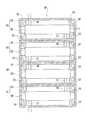
次に、図2、図3を用いて発電モジュール3に内蔵された小型改質装置40について説明する。ここで、図2は燃料電池式発電システム1の構成を示したブロック図であり、図3は小型改質装置40を一部破断して示した図面である。  Next, thesmall reformer 40 built in thepower generation module 3 will be described with reference to FIGS. Here, FIG. 2 is a block diagram showing the configuration of the fuel cell typepower generation system 1, and FIG. 3 is a drawing in which thesmall reformer 40 is partially broken.

図2、図3に示すように、小型改質装置40は、燃料タンク8から供給された燃料9を蒸発させるための蒸発器41と、蒸発器41で気化した燃料9から水素ガスと二酸化炭素ガスを生成するための改質反応器42と、改質反応器42から供給された混合気に含まれる一酸化炭素ガスと水から二酸化炭素と水素ガスを生成するための水性シフト反応器43と、水性シフト反応器43から供給された混合気に含まれる一酸化炭素ガスを酸化させて一酸化炭素ガスを除去するための選択酸化反応器44と、を備える。蒸発器41、改質反応器42、水性シフト反応器43、選択酸化反応器44の順に下から積み重なっている。これら反応器41〜44のうち改質反応器42、水性シフト反応器43及び選択酸化反応器44が、本発明の反応器を適用した実施の形態における触媒反応器である。  As shown in FIGS. 2 and 3, thesmall reformer 40 includes anevaporator 41 for evaporating thefuel 9 supplied from thefuel tank 8, and hydrogen gas and carbon dioxide from thefuel 9 vaporized by theevaporator 41. A reformingreactor 42 for generating gas, and anaqueous shift reactor 43 for generating carbon dioxide and hydrogen gas from carbon monoxide gas and water contained in the gas mixture supplied from the reformingreactor 42; Aselective oxidation reactor 44 for oxidizing the carbon monoxide gas contained in the air-fuel mixture supplied from theaqueous shift reactor 43 to remove the carbon monoxide gas. Theevaporator 41, the reformingreactor 42, theaqueous shift reactor 43, and theselective oxidation reactor 44 are stacked in this order from the bottom. Among thesereactors 41 to 44, the reformingreactor 42, theaqueous shift reactor 43 and theselective oxidation reactor 44 are catalytic reactors in an embodiment to which the reactor of the present invention is applied.

蒸発器41、改質反応器42、水性シフト反応器43及び選択酸化反応器44は何れも、反応を引き起こすための内部空間を形成した反応容器本体50と、反応容器本体50を内包した断熱パッケージ52と、を備える。  Theevaporator 41, the reformingreactor 42, theaqueous shift reactor 43, and theselective oxidation reactor 44 are each a reaction vesselmain body 50 that forms an internal space for causing a reaction, and a heat insulating package that encloses the reaction vesselmain body 50. 52.

蒸発器41、改質反応器42、水性シフト反応器43及び選択酸化反応器44の何れの断熱パッケージ52も、ガラス等の比較的熱伝導率の低い断熱材で形成されている。断熱パッケージ52の内壁には、Au、Ag、Al等で形成された輻射反射膜(図示略)が形成されている。輻射反射膜は赤外線を含む電磁波に対して高反射率で反射するものであり、内部の反応容器本体50で発された電磁波が輻射反射膜で反射されることによって輻射反射膜の外側に位置する断熱パッケージ52に熱が伝わることが抑えられている。これにより、電磁波による輻射熱が断熱パッケージ52外に放熱することを防止できるようになっている。  All the heat insulation packages 52 of theevaporator 41, the reformingreactor 42, theaqueous shift reactor 43, and theselective oxidation reactor 44 are formed of a heat insulating material having a relatively low thermal conductivity such as glass. On the inner wall of theheat insulation package 52, a radiation reflection film (not shown) made of Au, Ag, Al or the like is formed. The radiation reflection film reflects the electromagnetic wave including infrared rays with high reflectivity, and the electromagnetic wave emitted from the internalreaction vessel body 50 is reflected by the radiation reflection film, and is located outside the radiation reflection film. It is suppressed that heat is transmitted to theheat insulation package 52. Thereby, it is possible to prevent radiant heat due to electromagnetic waves from radiating outside theheat insulating package 52.

また、蒸発器41、改質反応器42、水性シフト反応器43及び選択酸化反応器44の何れについても、断熱パッケージ52内の内部空間が真空或いは減圧雰囲気に設けられているか、又は断熱パッケージ52内の内部空間にメチル基若しくはエチル基の水素を塩素やフッ素で置換した多ハロゲン化誘導体ガス(フレオン(商品名)ガス)又は炭酸ガス等の冷媒が充填されている。多ハロゲン化誘導体ガスとしては、トリクロロフルオロメタン、ジクロロジフルオロメタン等がある。  Further, in any of theevaporator 41, the reformingreactor 42, theaqueous shift reactor 43, and theselective oxidation reactor 44, the internal space in theheat insulation package 52 is provided in a vacuum or a reduced pressure atmosphere, or theheat insulation package 52. The interior space is filled with a refrigerant such as polyhalogenated derivative gas (Freon (trade name) gas) or carbon dioxide gas in which methyl or ethyl group hydrogen is replaced with chlorine or fluorine. Examples of the multihalogenated derivative gas include trichlorofluoromethane and dichlorodifluoromethane.

蒸発器41、改質反応器42、水性シフト反応器43及び選択酸化反応器44の何れについても、断熱パッケージ52の内部空間の入隅には、支持体53,53,…がそれぞれ配設されている。そして、反応容器本体50は、これら支持体53,53,…により支持された状態で断熱パッケージ52の内壁から離れるようにして、断熱パッケージ52の内側に配設されている。  In any of theevaporator 41, the reformingreactor 42, theaqueous shift reactor 43, and theselective oxidation reactor 44, supports 53, 53,. ing. The reaction vesselmain body 50 is disposed inside theheat insulation package 52 so as to be separated from the inner wall of theheat insulation package 52 while being supported by thesesupports 53, 53,.

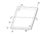
次に、反応容器本体50について図4、図5を用いて説明する。ここで、図4は反応容器本体50を斜視して示した透視図であり、図5は図4のV-V線に沿った断面図である。  Next, the reaction vesselmain body 50 will be described with reference to FIGS. Here, FIG. 4 is a perspective view showing thereaction container body 50 in a perspective view, and FIG. 5 is a cross-sectional view taken along the line V-V in FIG.

蒸発器41、改質反応器42、水性シフト反応器43及び選択酸化反応器44の何れの反応容器本体50も、シリコン結晶、アルミニウム、ガラス等の材料から四角形の平板状に形成された二枚の基板54,55から構成されている。これら基板54,55を貼り合わせることによって、内部空間としてのチャンバー56がこれら基板54,55の接合部に形成され、反応容器本体50が形成されている。  The reaction vesselmain body 50 of each of theevaporator 41, the reformingreactor 42, theaqueous shift reactor 43, and theselective oxidation reactor 44 is formed of a rectangular flat plate made of a material such as silicon crystal, aluminum, or glass. The board |substrates 54 and 55 are comprised. By laminating thesesubstrates 54 and 55, achamber 56 as an internal space is formed at the joint between thesesubstrates 54 and 55, and thereaction vessel body 50 is formed.

具体的には、第一基板54の一方の面には実質的に平面視四角形をした凹部56aが形成されており、第一基板54の凹部56a側の面を第二基板55に向かい合わせて第一基板54と第二基板55を接合することによって薄型直方体状のチャンバー56が形成されている。なお、図5において第一基板54が第二基板55よりも厚く示されているが、ほぼ同じ厚さであっても良い。第一基板54、第二基板55はいずれもシリコン基板、ガラス基板、アルミニウム等の金属基板から選択できるが熱伝導率の低いものが好ましい。  Specifically, aconcave portion 56 a having a substantially square shape in plan view is formed on one surface of thefirst substrate 54, and the surface on theconcave portion 56 a side of thefirst substrate 54 faces thesecond substrate 55. A thinrectangular parallelepiped chamber 56 is formed by bonding thefirst substrate 54 and thesecond substrate 55. Although thefirst substrate 54 is shown to be thicker than thesecond substrate 55 in FIG. 5, the thickness may be substantially the same. Both thefirst substrate 54 and thesecond substrate 55 can be selected from a metal substrate such as a silicon substrate, a glass substrate, and aluminum, but preferably have a low thermal conductivity.

また、第一基板54の一つの角部には、反応容器本体50の外側から凹部56aに通じる切欠き57aが形成され、この第一基板54の一つの角部に対角に位置する第二基板55における角部には、反応容器本体50の外側から凹部56aに通じる切欠き58aが形成されており、第一基板54と第二基板55が接合されることによってこれら切欠き57a,58aがチャンバー56まで通じる流路口となる。これら流路口は、第一基板54及び第二基板55を平面視した場合のチャンバー56の対角位置に配設されている。一方の切欠き57aからなる流路口には流入管57(図3に図示)が接続されており、他方の切欠き58aからなる流路口には流出管58が接続されている。流入管57は断熱パッケージ52を貫通して反応容器本体50から断熱パッケージ52の外部にまで延出しており、流出管58も断熱パッケージ52を貫通して反応容器本体50から断熱パッケージ52の外部にまで延出している。  In addition, anotch 57a is formed at one corner of thefirst substrate 54 from the outside of the reaction vesselmain body 50 to therecess 56a, and a second corner located diagonally at one corner of thefirst substrate 54 is formed. Anotch 58a is formed at the corner of thesubstrate 55 from the outside of the reaction vesselmain body 50 to therecess 56a. When thefirst substrate 54 and thesecond substrate 55 are joined, thenotches 57a and 58a are formed. It becomes a channel opening leading to thechamber 56. These channel openings are arranged at diagonal positions of thechamber 56 when thefirst substrate 54 and thesecond substrate 55 are viewed in plan. An inflow pipe 57 (shown in FIG. 3) is connected to the flow path opening made of onenotch 57a, and anoutflow pipe 58 is connected to the flow path opening made of theother notch 58a. Theinflow pipe 57 passes through theheat insulation package 52 and extends from thereaction container body 50 to the outside of theheat insulation package 52, and theoutflow pipe 58 also passes through theheat insulation package 52 and extends from thereaction container body 50 to the outside of theheat insulation package 52. It extends to.

蒸発器41の流入管57は図1に示された吸入ニップル部37に通じており、燃料タンク8に貯蔵された燃料9が吸入ニップル部37及び流入管57を通じて蒸発器41のチャンバー56に供給されるようになっている。また、蒸発器41の流入管57と吸入ニップル部37との間には、ポンプ(図示略)が設けられており、このポンプによって蒸発器41の流入管57に流れ込む燃料9の流量を調節できるようになっている。  Theinflow pipe 57 of theevaporator 41 communicates with the suction nipple portion 37 shown in FIG. 1, and thefuel 9 stored in thefuel tank 8 is supplied to thechamber 56 of theevaporator 41 through the suction nipple portion 37 and theinflow pipe 57. It has come to be. A pump (not shown) is provided between theinflow pipe 57 of theevaporator 41 and the suction nipple portion 37, and the flow rate of thefuel 9 flowing into theinflow pipe 57 of theevaporator 41 can be adjusted by this pump. It is like that.

また、図3に示すように、蒸発器41の流出管58は改質反応器42の流入管57に通じており、改質反応器42の流出管58は水性シフト反応器43の流入管57に通じており、水性シフト反応器43の流出管58は選択酸化反応器44の流入管57に通じている。選択酸化反応器44の流出管58は、後述する燃料電池91の燃料極にまで通じている。また、選択酸化反応器44のチャンバー56には空気導入管60が通じており、この空気導入管60は断熱パッケージ52を貫通して外部にまで延出している。この空気導入管60はバルブ又はポンプを介してスリット13にまで通じており、酸素を含む外気がスリット13及び空気導入管60を介して選択酸化反応器44のチャンバー56に供給されるようになっている。  Further, as shown in FIG. 3, theoutflow pipe 58 of theevaporator 41 communicates with theinflow pipe 57 of the reformingreactor 42, and theoutflow pipe 58 of the reformingreactor 42 is connected to theinflow pipe 57 of theaqueous shift reactor 43. Theoutflow pipe 58 of theaqueous shift reactor 43 communicates with theinflow pipe 57 of theselective oxidation reactor 44. Theoutflow pipe 58 of theselective oxidation reactor 44 leads to a fuel electrode of afuel cell 91 described later. Anair introduction pipe 60 communicates with thechamber 56 of theselective oxidation reactor 44. Theair introduction pipe 60 extends through theheat insulating package 52 to the outside. Theair introduction pipe 60 leads to theslit 13 through a valve or a pump, and outside air containing oxygen is supplied to thechamber 56 of theselective oxidation reactor 44 through theslit 13 and theair introduction pipe 60. ing.

図5に示すように、蒸発器41、改質反応器42、水性シフト反応器43及び選択酸化反応器44の何れの反応容器本体50でも、第一基板54の凹部56aの底面には、電熱膜51が成膜されている。電熱膜51は、電気抵抗性発熱体、半導体性発熱体を薄膜状に形成したものであり、電流が流れたり電圧が印加されたりすることによって電気エネルギーで発熱するものである。第一基板54の離れた二箇所それぞれには電熱膜51まで通じたスルーホールが形成されており、これらスルーホールに導電性材料が埋め込まれている。これらスルーホールの導電性材料にはリード線(図示略)がそれぞれ接続されており、どちらのリード線も断熱パッケージ52を貫通して外部にまで延出しており、リード線を通じて電熱膜51に電気エネルギーが供給されるようになっている。  As shown in FIG. 5, in anyreaction vessel body 50 of theevaporator 41, the reformingreactor 42, theaqueous shift reactor 43, and theselective oxidation reactor 44, the bottom surface of therecess 56 a of thefirst substrate 54 is electrically heated. Afilm 51 is formed. Theelectrothermal film 51 is formed by forming an electric resistance heating element and a semiconductor heating element in a thin film shape, and generates heat by electric energy when a current flows or a voltage is applied. Through holes extending to theelectrothermal film 51 are formed at two locations apart from thefirst substrate 54, and a conductive material is embedded in these through holes. Lead wires (not shown) are respectively connected to the conductive materials of these through holes, and both lead wires extend through theheat insulating package 52 to the outside and are electrically connected to theelectrothermal film 51 through the lead wires. Energy is being supplied.

図5に示すように、蒸発器41を除く改質反応器42、水性シフト反応器43及び選択酸化反応器44の何れの反応容器本体50でも、触媒膜59が電熱膜51に積層されてチャンバー56内において露出している。触媒膜59は、担体に触媒を分散させ、その担体に触媒を担持したものである。担体としては、金属酸化物等の多孔質性物質を用いることができる。触媒としては、一つ又は複数の金属種、一つ又は複数の金属酸化物、これら金属種と金属酸化物を組み合わせたものを用いることができる。特に、触媒膜59に含まれる触媒は不均一系触媒である。  As shown in FIG. 5, in any reaction vesselmain body 50 of the reformingreactor 42, theaqueous shift reactor 43, and theselective oxidation reactor 44 excluding theevaporator 41, thecatalyst film 59 is laminated on theelectrothermal film 51 to form a chamber. 56 is exposed. Thecatalyst film 59 is obtained by dispersing a catalyst on a carrier and carrying the catalyst on the carrier. As the carrier, a porous substance such as a metal oxide can be used. As the catalyst, one or more metal species, one or more metal oxides, or a combination of these metal species and metal oxides can be used. In particular, the catalyst contained in thecatalyst film 59 is a heterogeneous catalyst.

また、改質反応器42、水性シフト反応器43及び選択酸化反応器44の間で、触媒膜59は同じ材料で形成されていても良いし、異なる材料で形成されていても良い。また、改質反応器42、水性シフト反応器43及び選択酸化反応器44何れでも、一つの反応器の触媒膜59が一種類の材料で形成されていても良いし、複数種類の材料で形成されてチャンバー56内の場所によって異なっていても良い。  Further, between the reformingreactor 42, theaqueous shift reactor 43, and theselective oxidation reactor 44, thecatalyst film 59 may be formed of the same material, or may be formed of different materials. In any of the reformingreactor 42, theaqueous shift reactor 43, and theselective oxidation reactor 44, thecatalyst film 59 of one reactor may be formed of one kind of material, or may be formed of a plurality of kinds of materials. It may be different depending on the place in thechamber 56.

特に、改質反応器42の触媒膜59には、化学反応式(1)のようにメタノールと水とを反応させて二酸化炭素と水を生成することを促進させる触媒が担持されている。
CH3OH+H2O→3H2+CO2 … (1)
In particular, thecatalyst film 59 of the reformingreactor 42 carries a catalyst that promotes the generation of carbon dioxide and water by reacting methanol and water as in chemical reaction formula (1).
CH3 OH + H2 O → 3H2 + CO2 (1)

改質反応器42の触媒膜59に含まれる触媒としては、Cu/Zn系触媒(Cu/ZnO触媒も含む。)が挙げられる。  Examples of the catalyst included in thecatalyst film 59 of the reformingreactor 42 include a Cu / Zn-based catalyst (including a Cu / ZnO catalyst).

また、水性シフト反応器43の触媒膜59には、化学反応式(2)のように一酸化炭素と水を反応させて二酸化炭素と水素を生成することを促進させる触媒が担持されている。
CO+H2O→CO2+H2 … (2)
Thecatalyst film 59 of theaqueous shift reactor 43 carries a catalyst that promotes the generation of carbon dioxide and hydrogen by reacting carbon monoxide and water as shown in chemical reaction formula (2).
CO + H2 O → CO2 + H2 (2)

また、選択酸化反応器44の触媒膜59には、化学反応式(3)のように混合気中の一酸化炭素を選択して、一酸化炭素と酸素を反応させて二酸化炭素を生成することを促進させる触媒が担持されている。
2CO+O2→2CO2 … (3)
Thecatalyst film 59 of theselective oxidation reactor 44 selects carbon monoxide in the air-fuel mixture as shown in chemical reaction formula (3), and reacts carbon monoxide with oxygen to generate carbon dioxide. The catalyst which promotes is carried.
2CO + O2 → 2CO2 (3)

ここで触媒膜59の熱伝導率は第一基板54の熱伝導率よりも高くなるように設計されている。例えば、改質反応器42において、Cu/Zn系触媒の触媒膜59の熱伝導率はおおよそ3〜10〔W/m・K〕であるから、第一基板54がガラスのように1〜2〔W/m・K〕の低熱伝導率材料である。触媒膜59の熱伝導率が第一基板54の熱伝導率よりも高いと、電熱膜51で発した熱が第一基板54よりも触媒膜59側に伝導するので、吸熱反応である触媒反応が効率よく起こる。  Here, the thermal conductivity of thecatalyst film 59 is designed to be higher than the thermal conductivity of thefirst substrate 54. For example, in the reformingreactor 42, the thermal conductivity of thecatalyst film 59 of the Cu / Zn-based catalyst is approximately 3 to 10 [W / m · K], so thefirst substrate 54 is 1 to 2 like glass. [W / m · K] Low thermal conductivity material. If the thermal conductivity of thecatalyst film 59 is higher than the thermal conductivity of thefirst substrate 54, the heat generated by theelectrothermal film 51 is conducted to thecatalyst film 59 side than thefirst substrate 54, and thus a catalytic reaction that is an endothermic reaction. Happens efficiently.

なお、本実施形態では蒸発器41のチャンバー56内には触媒膜が設けられていない。  In this embodiment, no catalyst film is provided in thechamber 56 of theevaporator 41.

次に、燃料電池91について説明する。燃料電池91は、触媒を担持させた燃料極(カソード)と、触媒を担持させた空気極(アノード)と、燃料極と空気極との間に挟まれたフィルム状のイオン伝導膜と、を具備するものである。  Next, thefuel cell 91 will be described. Thefuel cell 91 includes a fuel electrode (cathode) carrying a catalyst, an air electrode (anode) carrying a catalyst, and a film-like ion conductive membrane sandwiched between the fuel electrode and the air electrode. It has.

燃料電池91においては、電気化学反応式(4)に示すように、燃料極に水素ガスが供給されると、燃料極の触媒により電子の分離した水素イオンが発生し、水素イオンがイオン伝導膜を通じて空気極へ伝導し、燃料極から電子が取り出されるようになっている。
2→2H++2e- … (4)
一方、電気化学反応式(5)に示すように、空気極に酸素ガスが供給されると、イオン導電膜を通過した水素イオンと、酸素ガスと、電子とが反応して、水が副生成物として生成されるようになっている。
2H++1/2O2+2e-→H2O … (5)
燃料電池91で以上のような電気化学反応が起こることによって、電気エネルギーが生成されるようになっている。
In thefuel cell 91, as shown in the electrochemical reaction formula (4), when hydrogen gas is supplied to the fuel electrode, hydrogen ions from which electrons are separated are generated by the catalyst of the fuel electrode, and the hydrogen ions are ion-conducting membrane. It is conducted to the air electrode through, and electrons are taken out from the fuel electrode.
H2 → 2H+ + 2e (4)
On the other hand, as shown in the electrochemical reaction equation (5), when oxygen gas is supplied to the air electrode, hydrogen ions that have passed through the ion conductive film, oxygen gas, and electrons react to generate water as a by-product. It is generated as a product.
2H+ + 1 / 2O2 + 2e → H2 O (5)
Electrical energy is generated by the electrochemical reaction as described above occurring in thefuel cell 91.

次に、燃料電池式発電システム1の動作について説明する。
まず、燃料電池式発電システム1が起動すると、蒸発器41、改質反応器42、水性シフト反応器43及び選択酸化反応器44それぞれの電熱膜51に電気エネルギーが供給され、電熱膜51が発熱する。電熱膜51で発した熱が触媒膜59及び反応容器本体50に伝導するが、触媒膜59の熱伝導率が第一基板54の熱伝導率よりも高いため、触媒膜59に熱伝導しやすい。
Next, the operation of the fuel cellpower generation system 1 will be described.
First, when the fuel cell typepower generation system 1 is activated, electric energy is supplied to theelectrothermal films 51 of theevaporator 41, the reformingreactor 42, theaqueous shift reactor 43, and theselective oxidation reactor 44, and theelectrothermal film 51 generates heat. To do. The heat generated by theelectrothermal film 51 is conducted to thecatalyst film 59 and the reaction vesselmain body 50. However, since the thermal conductivity of thecatalyst film 59 is higher than the thermal conductivity of thefirst substrate 54, the heat is easily conducted to thecatalyst film 59. .

一方、発電モジュール3内の各バルブ・各ポンプの動作により、外部の空気がスリット13,13,…に吸引されて燃料電池91の空気極及び選択酸化反応器44のチャンバー56に供給されるとともに、燃料タンク8内の燃料9が吸入ニップル部37に吸引され蒸発器41の流入管57を通じて蒸発器41のチャンバー56に供給される。  On the other hand, by the operation of each valve and each pump in thepower generation module 3, external air is sucked into theslits 13, 13,... And supplied to the air electrode of thefuel cell 91 and thechamber 56 of theselective oxidation reactor 44. Thefuel 9 in thefuel tank 8 is sucked into the suction nipple portion 37 and supplied to thechamber 56 of theevaporator 41 through theinflow pipe 57 of theevaporator 41.

燃料9は蒸発器41のチャンバー56を流れている時に蒸発器41の電熱膜51の熱によって蒸発する。燃料9の気化により燃料9がメタノールと水との混合気に相変化し、蒸発器41のチャンバー56内の気圧が高くなって対流が生じ、混合気が流体として化学的に変化しながら蒸発器41から改質反応器42、水性シフト反応器43、選択酸化反応器44及び燃料電池91までこの順に流動する。  Thefuel 9 is evaporated by the heat of theelectrothermal film 51 of theevaporator 41 while flowing through thechamber 56 of theevaporator 41. The vaporization of thefuel 9 causes thefuel 9 to undergo a phase change to a mixture of methanol and water, the atmospheric pressure in thechamber 56 of theevaporator 41 increases and convection occurs, and the evaporator changes while the mixture changes chemically as a fluid. From 41 to the reformingreactor 42, theaqueous shift reactor 43, theselective oxidation reactor 44 and thefuel cell 91 flow in this order.

混合気は改質反応器42のチャンバー56を流動している時に改質反応器42の電熱膜51によって加熱され、更に改質反応器42の触媒膜59によって上記化学反応式(1)のような反応が促進される。これにより、改質反応器42では、混合気から水素ガスと二酸化炭素ガスが生成される。  The air-fuel mixture is heated by theelectrothermal film 51 of the reformingreactor 42 while flowing in thechamber 56 of the reformingreactor 42, and further, by thecatalyst film 59 of the reformingreactor 42, the chemical reaction formula (1) above. Reaction is promoted. Thereby, in the reformingreactor 42, hydrogen gas and carbon dioxide gas are generated from the air-fuel mixture.

また、改質反応器42のチャンバー56を流れている混合気が完全に水素ガスと二酸化炭素ガスに改質されない場合もあり、化学反応式(6)のような化学反応も僅かに起こり、二酸化炭素ガス、一酸化炭素ガス及び水が生成される。
2CH3OH+H2O→5H2+CO+CO2 … (6)
In addition, the air-fuel mixture flowing through thechamber 56 of the reformingreactor 42 may not be completely reformed to hydrogen gas and carbon dioxide gas, and a chemical reaction such as the chemical reaction formula (6) slightly occurs, and the dioxide dioxide. Carbon gas, carbon monoxide gas and water are produced.
2CH3 OH + H2 O → 5H2 + CO + CO2 (6)

改質反応器42のチャンバー56で生成された水素ガス、二酸化炭素ガス、一酸化炭素ガス及び水蒸気からなる混合気は、水性シフト反応器43のチャンバー56に供給される。水性シフト反応器43のチャンバー56に供給された混合気は、そのチャンバー56を流動している時に水性シフト反応器43の電熱膜51によって加熱され、更に水性シフト反応器43の触媒膜59によって上記化学反応式(2)のような反応が促進される。これにより、混合気が無毒化される。  The air-fuel mixture composed of hydrogen gas, carbon dioxide gas, carbon monoxide gas and water vapor generated in thechamber 56 of the reformingreactor 42 is supplied to thechamber 56 of theaqueous shift reactor 43. The air-fuel mixture supplied to thechamber 56 of theaqueous shift reactor 43 is heated by theelectrothermal film 51 of theaqueous shift reactor 43 while flowing through thechamber 56, and further, thecatalyst film 59 of theaqueous shift reactor 43 performs the above operation. Reaction such as chemical reaction formula (2) is promoted. Thereby, the air-fuel mixture is detoxified.

そして、水性シフト反応器43を流動した混合気は、選択酸化反応器44のチャンバー56に供給される。また、外気中の空気がスリット13及び空気導入管60を通じて選択酸化反応器44のチャンバー56に供給され、混合気と空気が混合する。空気を含む混合気が、選択酸化反応器44のチャンバー56を流動している時に選択酸化反応器44の電熱膜51によって加熱され、更に選択酸化反応器44の触媒膜59によって上記化学反応式(3)のような反応が促進される。ここで、選択酸化反応器44の触媒膜59が化学反応式(3)の化学反応を選択的に促進するから、混合気に含まれる水素は殆ど酸化しない。  Then, the air-fuel mixture that has flowed through theaqueous shift reactor 43 is supplied to thechamber 56 of theselective oxidation reactor 44. Further, air in the outside air is supplied to thechamber 56 of theselective oxidation reactor 44 through theslit 13 and theair introduction pipe 60, and the air-fuel mixture and air are mixed. The air-fuel mixture containing air is heated by theelectrothermal film 51 of theselective oxidation reactor 44 when flowing in thechamber 56 of theselective oxidation reactor 44, and further, the above chemical reaction formula ( The reaction as in 3) is promoted. Here, since thecatalyst film 59 of theselective oxidation reactor 44 selectively promotes the chemical reaction of the chemical reaction formula (3), hydrogen contained in the air-fuel mixture is hardly oxidized.

選択酸化反応器44のチャンバー56を流れている混合気が流出管58に至る時点では、その混合気には一酸化炭素が殆ど含まれず、水素ガス及び二酸化炭素ガスの濃度が非常に高い。そして、水素ガス及び二酸化炭素ガスの濃度が高い混合気は、選択酸化反応器44の流出管58を流れて、燃料電池91の燃料極に供給される。燃料電池91では、混合気中の水素ガスが燃料極で上記電気化学反応式(4)のような反応をし、スリット13,13,…を通じて空気極に酸素ガスが供給されて空気極で上記電気化学反応式(5)のような反応をする。電気化学反応式(4)、(5)のような電気化学反応によって燃料電池91で電気エネルギーが生成される。生成された電気エネルギーは外部のデバイスに供給されたり、内部の電熱膜51、ポンプ、バルブその他を駆動するためのエネルギーに利用されたり、内部の蓄電部に貯蔵されたりする。また、空気極で生成された水は、通気孔33,33,…を通じて外部に排出されたり、排水管34,6を通じて排水容器7に排水されたりする。排水容器7では水が貯留される。  When the air-fuel mixture flowing through thechamber 56 of theselective oxidation reactor 44 reaches theoutflow pipe 58, the air-fuel mixture hardly contains carbon monoxide, and the concentrations of hydrogen gas and carbon dioxide gas are very high. The air-fuel mixture having a high concentration of hydrogen gas and carbon dioxide gas flows through theoutflow pipe 58 of theselective oxidation reactor 44 and is supplied to the fuel electrode of thefuel cell 91. In thefuel cell 91, hydrogen gas in the gas mixture reacts as shown in the electrochemical reaction formula (4) at the fuel electrode, and oxygen gas is supplied to the air electrode through theslits 13, 13,. Reaction is performed as shown in the electrochemical reaction formula (5). Electric energy is generated in thefuel cell 91 by an electrochemical reaction such as the electrochemical reaction formulas (4) and (5). The generated electrical energy is supplied to an external device, used as energy for driving the internalelectrothermal film 51, a pump, a valve, and the like, or stored in an internal power storage unit. Further, the water generated at the air electrode is discharged to the outside through the vent holes 33, 33,... Or drained into thedrainage container 7 through thedrain pipes 34, 6. Water is stored in thedrainage container 7.

次に、本実施形態の効果について説明する。
電熱膜51に触媒膜59が直接積層されているので、触媒膜59に熱伝導しやすくなる。そのため、電熱膜51で加熱を開始してから触媒膜59が所望の温度(改質反応器42の場合には280℃)にまで上昇するのに要する時間を短縮することができ、燃料9の触媒反応が効率よく起こるまでの時間も短縮することができる。
Next, the effect of this embodiment will be described.
Since thecatalyst film 59 is directly laminated on theelectrothermal film 51, heat conduction to thecatalyst film 59 is facilitated. Therefore, the time required for thecatalyst film 59 to rise to a desired temperature (280 ° C. in the case of the reforming reactor 42) after heating is started by theelectrothermal film 51 can be shortened. The time until the catalytic reaction occurs efficiently can also be shortened.

また、第一基板54の熱伝導率よりも触媒膜59の熱伝導率が高いため、電熱膜51で発した熱が第一基板54よりも触媒膜59に伝導しやすい。そのため、電熱膜51で加熱を開始してから触媒膜59が所望の温度にまで上昇するのに要する時間を短縮することができるとともに、電熱膜51で発した熱が第一基板54の加熱よりも触媒膜59の加熱に効率よく用いられ、電熱膜51の省エネルギーを図ることができる。  Further, since the thermal conductivity of thecatalyst film 59 is higher than the thermal conductivity of thefirst substrate 54, the heat generated by theelectrothermal film 51 is more easily conducted to thecatalyst film 59 than thefirst substrate 54. Therefore, it is possible to shorten the time required for thecatalyst film 59 to rise to a desired temperature after heating is started by theelectrothermal film 51, and the heat generated by theelectrothermal film 51 is less than the heating of thefirst substrate 54. Is also used efficiently for heating thecatalyst film 59, and energy saving of theelectrothermal film 51 can be achieved.

また、反応容器本体50の内部空間が直方体状のチャンバー56であるため、第一基板54及び第二基板55の一部がチャンバー56内へ突出していない。そのため、反応容器本体50の熱容量が小さく、電熱膜51で発した熱が触媒膜59の加熱に効率よく用いられる。更に、チャンバー56で生じる圧力損失が小さく、燃料9をチャンバー56に供給して生成物をチャンバー56から排出するために要する負荷が軽減される。  In addition, since the internal space of the reaction vesselmain body 50 is arectangular parallelepiped chamber 56, a part of thefirst substrate 54 and thesecond substrate 55 does not protrude into thechamber 56. Therefore, the heat capacity of the reaction vesselmain body 50 is small, and the heat generated by theelectrothermal film 51 is efficiently used for heating thecatalyst film 59. Furthermore, the pressure loss generated in thechamber 56 is small, and the load required to supply thefuel 9 to thechamber 56 and discharge the product from thechamber 56 is reduced.

以下、改質反応器42の反応容器本体50を変形した場合について例を挙げて説明するが、改質反応器42の場合と同様に水性シフト反応器43及び選択酸化反応器44それぞれの反応容器本体50も以下のように変形することができる。  Hereinafter, the case where the reaction vesselmain body 50 of the reformingreactor 42 is deformed will be described by way of example. However, similarly to the case of the reformingreactor 42, the reaction vessels of theaqueous shift reactor 43 and theselective oxidation reactor 44, respectively. Themain body 50 can also be modified as follows.

〔変形例1〕
図6には、変形した反応容器本体150が示されている。
反応容器本体150が図4に示された反応容器本体50と異なることは、流入口157a、流出口158aの軸方向である。つまり、図4に示された反応容器本体50では、切欠き57a,58aによる流路口の軸方向がチャンバー56の平面形状四角形の辺に対して直交しているのに対し、図6に示された反応容器本体150では、流入口157a、流出口158aの軸方向が平面視してチャンバー156の対角線に一致している。また、図4に示された反応容器本体50では、チャンバー56の平面視形状が四角形でも特に長方形であるのに対し、図6に示された反応容器本体150では、チャンバー156の平面視形状が正方形である。チャンバー156の平面視形状が正方形であっても、チャンバー156の立体形状は直方体状である。
[Modification 1]
FIG. 6 shows a deformed reaction vesselmain body 150.
The reaction vesselmain body 150 differs from the reaction vesselmain body 50 shown in FIG. 4 in the axial direction of theinflow port 157a and theoutflow port 158a. That is, in the reaction vesselmain body 50 shown in FIG. 4, the axial direction of the flow path opening by thenotches 57a and 58a is orthogonal to the side of the planar square of thechamber 56, whereas FIG. In the reaction vesselmain body 150, the axial directions of theinlet 157a and theoutlet 158a coincide with the diagonal line of thechamber 156 in plan view. Further, in the reaction vesselmain body 50 shown in FIG. 4, the planar view shape of thechamber 56 is square or particularly rectangular, whereas in the reaction vesselmain body 150 shown in FIG. 6, the planar view shape of thechamber 156 is It is a square. Even if the planar view shape of thechamber 156 is a square, the three-dimensional shape of thechamber 156 is a rectangular parallelepiped shape.

以上のことを除いて、反応容器本体150は反応容器本体50と同一構成をしている。つまり、凹部が形成された第一基板にその凹部を蓋するように第二基板を第一基板に接合することによって、内部空間であるチャンバー156を有した反応容器本体150が形成される。また、その第一基板の凹部の壁面に電熱膜が成膜され、電熱膜に触媒膜が積層されている。更には、触媒膜の熱伝導率が第一基板の熱伝導率よりも高い。  Except for the above, the reaction vesselmain body 150 has the same configuration as the reaction vesselmain body 50. That is, thereaction vessel body 150 having thechamber 156 that is the internal space is formed by bonding the second substrate to the first substrate so as to cover the first substrate on which the recess is formed. An electrothermal film is formed on the wall surface of the recess of the first substrate, and a catalyst film is laminated on the electrothermal film. Furthermore, the thermal conductivity of the catalyst film is higher than the thermal conductivity of the first substrate.

〔変形例2〕
図7には、別の反応容器本体250が示されている。
反応容器本体250が図4に示された反応容器本体50と異なることは、チャンバー256の形状である。つまり、図4に示された反応容器本体50では、チャンバー56の平面視形状が四角形でも特に長方形であるのに対し、図7に示された反応容器本体250では、チャンバー256の平面視形状が菱形である。チャンバー256が平面視菱形を呈していても、チャンバー256の立体形状は六面体状である。
[Modification 2]
FIG. 7 shows another reaction vesselmain body 250.
Thereaction vessel body 250 is different from thereaction vessel body 50 shown in FIG. 4 in the shape of thechamber 256. That is, in the reaction vesselmain body 50 shown in FIG. 4, the planar view shape of thechamber 56 is square or particularly rectangular, whereas in the reaction vesselmain body 250 shown in FIG. It is a diamond. Even if thechamber 256 has a rhombus in plan view, the three-dimensional shape of thechamber 256 is a hexahedron.

また、図4に示された反応容器本体50では、チャンバー56の四つの角部がそれぞれ第一基板54の角の近傍に位置しているのに対し、図7に示されたチャンバー256の四つの角部がそれぞれ基板の辺の中点の近傍に位置している。また、図7に示された反応容器本体250では、流入口257a、流出口258aの軸方向が平面視してチャンバー256の対角線に一致している。  Further, in the reaction vesselmain body 50 shown in FIG. 4, the four corners of thechamber 56 are positioned in the vicinity of the corners of thefirst substrate 54, respectively, whereas the four corners of thechamber 256 shown in FIG. Each corner is located near the midpoint of the side of the substrate. In the reaction vesselmain body 250 shown in FIG. 7, the axial directions of theinlet 257a and the outlet 258a coincide with the diagonal line of thechamber 256 in plan view.

以上のことを除いて、反応容器本体250は反応容器本体50と同一構成をしている。つまり、凹部が形成された第一基板にその凹部を蓋するように第二基板を第一基板に接合することによって、内部空間であるチャンバー256を有した反応容器本体250が形成される。また、その第一基板の凹部の壁面に電熱膜が成膜され、電熱膜に触媒膜が積層されている。更には、触媒膜の熱伝導率が第一基板の熱伝導率よりも高い。  Except for the above, thereaction vessel body 250 has the same configuration as thereaction vessel body 50. That is, thereaction vessel body 250 having thechamber 256 that is the internal space is formed by bonding the second substrate to the first substrate so as to cover the concave portion on the first substrate on which the concave portion is formed. An electrothermal film is formed on the wall surface of the recess of the first substrate, and a catalyst film is laminated on the electrothermal film. Furthermore, the thermal conductivity of the catalyst film is higher than the thermal conductivity of the first substrate.

〔変形例3〕
図8には、別の反応容器本体350が示されている。
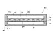
反応容器本体350が図5に示された反応容器本体50と異なることは、反応容器本体350には燃焼器361が備え付けられていることである。つまり、第二基板355は第一基板354と第三基板370との間に挟まれた状態でそれぞれの基板354,370に接合されている。第一基板354と第二基板355の接合部には、上記化学反応式(1)の反応が起こるチャンバー356が形成されており、第二基板355と第三基板370の接合部には、燃料を酸素と反応させて燃焼させるための燃焼用チャンバー371が形成されている。
[Modification 3]
FIG. 8 shows another reaction vesselmain body 350.
Thereaction vessel body 350 is different from thereaction vessel body 50 shown in FIG. 5 in that thereaction vessel body 350 is provided with acombustor 361. That is, thesecond substrate 355 is bonded to thesubstrates 354 and 370 while being sandwiched between thefirst substrate 354 and thethird substrate 370. Achamber 356 in which the reaction of the chemical reaction formula (1) occurs is formed at the joint between thefirst substrate 354 and thesecond substrate 355, and the fuel at the joint between thesecond substrate 355 and thethird substrate 370 is formed. Is formed with acombustion chamber 371 for reacting oxygen with oxygen and burning it.

第三基板370の第二基板355側の面には平面視四角形の凹部371aが形成されており、第三基板370に第二基板355を接合することによって凹部371aに蓋をして、燃焼用チャンバー371が形成されている。この燃焼用チャンバー371は薄型の直方体状に設けられている。  Aconcave portion 371a having a square shape in a plan view is formed on the surface of thethird substrate 370 on thesecond substrate 355 side, and theconcave portion 371a is covered with thethird substrate 370 by bonding thesecond substrate 355, and is used for combustion. Achamber 371 is formed. Thecombustion chamber 371 is provided in a thin rectangular parallelepiped shape.

また、第二基板355の第三基板370側の面であって燃焼用チャンバー371の内壁面を形成した部分には、燃焼用触媒372が設けられている。この燃焼用触媒372は、燃料9のメタノールを酸化させることを促進するものである。また、図示は省略するが、第三基板370側面には、燃焼用チャンバー371にまで通じる流入口及び流出口が設けられている。燃料タンク8から燃料9が流入口を通じて燃焼用チャンバー371に供給されるようになっているとともに外部から空気がスリット13(図1に図示)及び流入口を通じて燃焼用チャンバー371に供給され、生成物が燃焼用チャンバー371から流出口及び通気孔33(図1に図示)を通じて外部に排出されるようになっている。燃料9のうちメタノールが燃焼用チャンバー371中で酸化する。  Acombustion catalyst 372 is provided on a portion of thesecond substrate 355 on thethird substrate 370 side where the inner wall surface of thecombustion chamber 371 is formed. Thecombustion catalyst 372 promotes oxidation of methanol of thefuel 9. Although not shown, an inlet and an outlet that lead to thecombustion chamber 371 are provided on the side surface of thethird substrate 370.Fuel 9 is supplied from thefuel tank 8 to thecombustion chamber 371 through the inlet, and air is supplied from the outside to thecombustion chamber 371 through the slit 13 (shown in FIG. 1) and the inlet, and the product Is discharged from thecombustion chamber 371 to the outside through the outlet and the vent hole 33 (shown in FIG. 1). Methanol of thefuel 9 is oxidized in thecombustion chamber 371.

第一基板354の第二基板355側の面には平面視四角形の凹部356aが形成されており、第一基板354に第二基板355を接合することによって凹部356aに蓋をして、チャンバー356が形成されている。第二基板355の第一基板354側の面であってチャンバー356の内壁面を形成した部分には、電気抵抗性発熱体、半導体性薄膜発熱体等の電熱膜351が形成されている。電熱膜351上には触媒膜359が成膜されており、この触媒膜359がチャンバー356内において露出している。触媒膜359は、多孔質性物質等の担体に金属、金属酸化物等の触媒を分散させ、その担体に触媒を担持したものである。この触媒膜359の熱伝導率は第二基板355の熱伝導率よりも高い。以上のことを除いて、反応容器本体350は反応容器本体50と同一構成をしている。  Aconcave portion 356a having a rectangular shape in plan view is formed on the surface of thefirst substrate 354 on thesecond substrate 355 side. Theconcave portion 356a is covered by bonding thesecond substrate 355 to thefirst substrate 354, and thechamber 356 is covered. Is formed. On the surface of thesecond substrate 355 on thefirst substrate 354 side where the inner wall surface of thechamber 356 is formed, anelectrothermal film 351 such as an electric resistance heating element or a semiconductor thin film heating element is formed. Acatalyst film 359 is formed on theelectrothermal film 351, and thiscatalyst film 359 is exposed in thechamber 356. Thecatalyst film 359 is obtained by dispersing a catalyst such as a metal or a metal oxide on a carrier such as a porous substance and carrying the catalyst on the carrier. The thermal conductivity of thecatalyst film 359 is higher than the thermal conductivity of thesecond substrate 355. Except for the above, the reaction vesselmain body 350 has the same configuration as the reaction vesselmain body 50.

この反応容器本体350においては、起動時には電熱膜351によって反応容器本体350全体の加熱を行う。そして、電熱膜351によって燃焼用触媒372が所定温度(250℃〜300℃)まで昇温したら、燃焼用チャンバー371に燃料9を燃焼用チャンバー371に流入させ、燃焼用触媒372によって燃料9を触媒反応させることによって燃料9を燃焼させる。これにより、燃焼熱によってチャンバー356内の混合気が加熱されるとともに電熱膜351の発熱によって混合気が補助的に加熱され、触媒膜359によって混合気の触媒反応が促進される。  In the reaction vessel
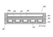
main body 350, the entire reaction vesselmain body 350 is heated by theelectrothermal film 351 at the time of activation. When thecombustion catalyst 372 is heated to a predetermined temperature (250 ° C. to 300 ° C.) by theelectrothermal film 351, thefuel 9 is caused to flow into thecombustion chamber 371 and thefuel 9 is catalyzed by thecombustion catalyst 372. Thefuel 9 is burned by reacting. Thus, the air-fuel mixture in thechamber 356 is heated by the combustion heat, and the air-fuel mixture is supplementarily heated by the heat generated by theelectrothermal film 351, and the catalytic reaction of the air-fuel mixture is promoted by thecatalyst film 359.

〔変形例4〕
図9には、別の反応容器本体450が示されている。この反応容器本体450においては、図8に示された反応容器本体350と同様に燃焼器461が備え付けられている。但し、反応容器本体350の燃焼器361では内部空間として直方体状のチャンバー371中で触媒燃焼が行われているのに対し、反応容器本体450の燃焼器461では内部空間として葛折り状のマイクロ流路471中で触媒燃焼が行われている。つまり、第三基板470の第二基板455側の面には葛折り状の溝471aが形成されており、第三基板470の溝471a側の面を第二基板455に向かい合わせて接合することによってマイクロ流路471が形成されている。また、第三基板470の溝471aの壁面には燃焼用触媒472が形成されており、燃焼用触媒472がマイクロ流路471内で露出している。このマイクロ流路471の一方の端部は吸入ニップル部37及びスリット13(図1に図示)に通じており、マイクロ流路471の他方の端部は通気孔33に通じている。そして、燃料タンク8から燃料9が吸入ニップル部37を通じてマイクロ流路471の一方の端部に供給されるとともに外部から空気がスリット13を通じてマイクロ流路471の一方の端部に供給され、燃料9がマイクロ流路471を流動している時に燃料9が燃焼用触媒472によって燃焼し、生成物がマイクロ流路471の他方の端部から通気孔33を通じて外部に排出されるようになっている。以上のことを除いて反応容器本体450は反応容器本体350と同じ構成をしている。
[Modification 4]
FIG. 9 shows another reaction vesselmain body 450. In the reaction vesselmain body 450, acombustor 461 is provided in the same manner as the reaction vesselmain body 350 shown in FIG. However, in thecombustor 361 of the reaction vesselmain body 350, catalytic combustion is performed in arectangular parallelepiped chamber 371 as an internal space, whereas in thecombustor 461 of the reaction vesselmain body 450, a distorted micro flow is used as the internal space. Catalytic combustion is performed in thepassage 471. That is, thegroove 471a is formed on the surface of thethird substrate 470 on thesecond substrate 455 side, and the surface of thethird substrate 470 on thegroove 471a side is opposed to thesecond substrate 455 and bonded. Thus, amicro flow channel 471 is formed. Further, acombustion catalyst 472 is formed on the wall surface of thegroove 471 a of thethird substrate 470, and thecombustion catalyst 472 is exposed in themicro flow channel 471. One end of themicro channel 471 communicates with the suction nipple portion 37 and the slit 13 (shown in FIG. 1), and the other end of themicro channel 471 communicates with the vent hole 33. Thefuel 9 is supplied from thefuel tank 8 through the suction nipple portion 37 to one end portion of themicro flow path 471 and air is supplied from the outside through theslit 13 to one end portion of themicro flow path 471. However, thefuel 9 is combusted by thecombustion catalyst 472 while flowing in themicro flow channel 471, and the product is discharged from the other end of themicro flow channel 471 to the outside through the vent hole 33. Except for the above, the reaction vesselmain body 450 has the same configuration as the reaction vesselmain body 350.

〔変形例5〕
図10には別の反応容器本体550の透視図が示されており、図11には、図10のXI-XI線に沿った断面の一部が示されている。この反応容器本体550が図4に示された反応容器本体50と異なることは、反応容器本体50には直方体状の内部空間としてチャンバー56が形成されているのに対し、この反応容器本体550には葛折り状の内部空間としてマイクロ流路556が形成されていることである。つまり、第一基板554の第二基板455側の面には葛折り状の溝556aが形成されており、第一基板554の溝556a側の面を第二基板555に向かい合わせて接合することによってマイクロ流路556が形成されている。マイクロ流路556の一方の端部において第二基板555には、マイクロ流路556まで通じた流入口557aが形成されており、マイクロ流路556の他方の端部において第二基板555には、マイクロ流路556まで通じた流出口558aが形成されている。
[Modification 5]
FIG. 10 shows a perspective view of another reaction vesselmain body 550, and FIG. 11 shows a part of a cross section taken along line XI-XI of FIG. The reaction vesselmain body 550 is different from the reaction vesselmain body 50 shown in FIG. 4 in that achamber 56 is formed as a rectangular parallelepiped internal space in the reaction vesselmain body 50. Is that themicro flow path 556 is formed as a twisted internal space. That is, thegroove 556a is formed on the surface of thefirst substrate 554 on thesecond substrate 455 side, and the surface of thefirst substrate 554 on thegroove 556a side is opposed to thesecond substrate 555 and bonded. Thus, amicro flow channel 556 is formed. Thesecond substrate 555 has aninflow port 557a at one end of themicro flow channel 556, and thesecond substrate 555 at the other end of themicro flow channel 556. Anoutlet 558a that leads to themicrochannel 556 is formed.

また、第一基板554の溝556aの壁面には電熱膜551が形成されている。マイクロ流路556の両端それぞれにおいて第一基板554には電熱膜551まで通じたスルーホールが形成されており、これらスルーホールに導電性材料が埋め込まれている。外部まで導かれたリード線がスルーホールで導電性材料に接続されており、リード線を通じて電熱膜551に電気エネルギーが供給されるようになっている。  In addition, anelectrothermal film 551 is formed on the wall surface of thegroove 556 a of thefirst substrate 554. At both ends of themicrochannel 556, through holes are formed in thefirst substrate 554 to theelectrothermal film 551, and a conductive material is embedded in these through holes. A lead wire led to the outside is connected to a conductive material through a through hole, and electric energy is supplied to theelectrothermal film 551 through the lead wire.

電熱膜551上には、触媒膜559が成膜されている。触媒膜559はマイクロ流路556内において露出している。触媒膜559は、多孔質性物質等の担体に金属、金属酸化物等の触媒を担持したものである。触媒膜559の熱伝導率は第一基板554の熱伝導率よりも高い。  Acatalyst film 559 is formed on theelectrothermal film 551. Thecatalyst film 559 is exposed in themicro flow channel 556. Thecatalyst film 559 is obtained by supporting a catalyst such as a metal or metal oxide on a carrier such as a porous substance. The thermal conductivity of thecatalyst film 559 is higher than the thermal conductivity of thefirst substrate 554.

この反応容器本体550では、マイクロ流路556の深さが次式(A)を満たすように設計されている。ここで、マイクロ流路556の深さをdchaとし、マイクロ流路556内での各化学種の有効拡散係数をDmとし、マイクロ流路556の一方の端部(流入口557a)から他方の端部(流出口558a)までの長さをLchaとし、マイクロ流路556内での混合気の平均流速をvとする。

Figure 2005087803
Thereaction vessel body 550 is designed such that the depth of themicrochannel 556 satisfies the following formula (A). Here, the depth of themicrochannel 556 is dcha , the effective diffusion coefficient of each chemical species in themicrochannel 556 is Dm, and the other end of the microchannel 556 (inlet 557a) is the other. The length to the end portion (outflow port 558a) is Lcha, and the average flow rate of the air-fuel mixture in themicrochannel 556 is v.
Figure 2005087803

また、この反応容器本体550では、触媒膜559の膜厚が次式(B)を満たすように設計されている。ここで、触媒膜559内での各化学種の有効拡散係数をDeAとし、触媒膜559の膜厚をdcatとする。

Figure 2005087803
Further, thereaction vessel body 550 is designed so that the thickness of thecatalyst film 559 satisfies the following formula (B). Here, the effective diffusion coefficient of each species in thecatalyst layer 559 and DeA, the thickness of thecatalyst film 559 and dcat.
Figure 2005087803

更に、この反応容器本体550では、触媒膜559の膜厚dcatとマイクロ流路556の深さdchaとの比が次式(C)を満たすように設計されている。

Figure 2005087803
Further, the reaction vesselmain body 550 is designed so that the ratio of the film thickness dcat of thecatalyst film 559 to the depth dcha of themicrochannel 556 satisfies the following formula (C).
Figure 2005087803

まず、式(A)について説明する。流体がマイクロ流路556の深さ方向に分子拡散し、触媒膜559に到達するまでの時間をtchaとしたら、次式(D)が成立する。

Figure 2005087803
First, formula (A) will be described. If the time required for the fluid to molecularly diffuse in the depth direction of themicrochannel 556 and reach thecatalyst film 559 is tcha , the following equation (D) is established.
Figure 2005087803

また、マイクロ流路556の一方の端部から他方の端部までの反応時間、つまり、混合気が平均流速vでマイクロ流路556の一方の端部から他方の端部までに流れる時間をtreacとしたら、次式(E)が成立する。

Figure 2005087803
Also, the reaction time from one end of themicrochannel 556 to the other end, that is, the time during which the air-fuel mixture flows from one end of themicrochannel 556 to the other end at the average flow velocity v is t.If reac , the following equation (E) is established.
Figure 2005087803

反応時間treacと拡散時間tchaとの比を変えてメタノール転化率(燃料9中のメタノールが全て化学反応式(1)のように改質した場合を1とする。)を計算すると、メタノール転化率とtcha/treacとの関係は図12に示すようになる。図12からわかるように、tcha/treac=0.1を境にメタノールの転化率が変わっている。すなわちtcha/treac≦0.1の場合には拡散速度が反応速度よりも速く、転化率が触媒膜559の反応性能に依存した反応律速となる。一方、tcha/treac>0.1の場合には、拡散速度が反応速度よりも遅く、転化率がマイクロ流路556内の拡散速度に依存した拡散律速となる。従って、tcha/treac≦0.1を満たせば触媒膜559の触媒の性能を最大限に利用することができ、tcha/treac≦0.1に対して式(D)、(E)を代入すると、式(A)が成立する。式(A)は、触媒を有するマイクロリアクタである改質反応器42、水性シフト反応器43及び選択酸化反応器44の何れにも適用可能であるが、流体となっている分子がマイクロリアクタの流路内にいるうちに、反応に要する温度に設定されている溝の表面に接することで気化反応を含む化学反応を引き起こすために拡散律速させないための条件式なので、触媒のない蒸発器41であっても、流れる流体の種類に大きな変化がないので適用することが可能である。すなわち、ここでいう反応とは反応物の化学変化を伴う反応のみならず、反応物の状態変化を伴うものも反応とする。When the ratio of the reaction time treac and the diffusion time tcha is changed to calculate the methanol conversion rate (when methanol in thefuel 9 is all reformed as in the chemical reaction formula (1), 1), methanol is calculated. The relationship between the conversion rate and tcha / treac is as shown in FIG. As can be seen from FIG. 12, the conversion rate of methanol changes at tcha / treac = 0.1. That is, in the case of tcha / treac ≦ 0.1, the diffusion rate is faster than the reaction rate, and the conversion rate becomes the reaction rate-limiting depending on the reaction performance of thecatalyst film 559. On the other hand, in the case of tcha / treac > 0.1, the diffusion rate is slower than the reaction rate, and the conversion rate becomes a diffusion rate control depending on the diffusion rate in themicrochannel 556. Accordingly, if tcha / treac ≦ 0.1 is satisfied, the catalyst performance of thecatalyst membrane 559 can be utilized to the maximum, and the equations (D) and (E) areobtained for tcha / treac ≦ 0.1. ) Is substituted, the formula (A) is established. Expression (A) can be applied to any of the reformingreactor 42, theaqueous shift reactor 43, and theselective oxidation reactor 44, which are microreactors having a catalyst. Theevaporator 41 without a catalyst is a conditional equation for preventing diffusion-control in order to cause a chemical reaction including a vaporization reaction by contacting the surface of the groove set to the temperature required for the reaction while inside. However, since there is no great change in the type of flowing fluid, it can be applied. That is, the reaction here refers not only to a reaction accompanied by a chemical change of the reactant, but also a reaction accompanied by a change in the state of the reactant.

次に、式(B)について説明する。触媒膜559内での分子輸送形態は、触媒膜の細孔径が1nm〜15nm程度であるから、細孔径と分子の平均自由行程との比が0.1以下になり、クヌーセン(Knudsen)拡散となる。  Next, the formula (B) will be described. The molecular transport mode in thecatalyst membrane 559 is such that the pore size of the catalyst membrane is about 1 nm to 15 nm, so the ratio of the pore size to the mean free path of the molecule is 0.1 or less, and Knudsen diffusion and Become.

また、触媒膜559の厚さ方向に分子拡散する時間をtcatとしたら、次式(F)が成立する。

Figure 2005087803
Further, when the time for molecular diffusion in the thickness direction of thecatalyst film 559 is tcat , the following equation (F) is established.
Figure 2005087803

反応時間treacと拡散時間tcatとの比を変えてメタノール転化率を計算すると、tcat/treac≦0.1の場合には拡散速度が反応速度よりも速く、転化率が触媒膜559の反応性能に依存した反応律速となる。一方、tcat/treac>0.1の場合には、拡散速度が反応速度よりも遅く、転化率が触媒膜559内の拡散速度に依存した拡散律速となる。従って、tcat/treac≦0.1を満たせば触媒膜559の触媒の性能を最大限に利用することができ、tcat/treac≦0.1に対して式(E)、(F)を代入すると、式(B)が成立する。When the methanol conversion rate is calculated by changing the ratio between the reaction time treac and the diffusion time tcat , when tcat / treac ≦ 0.1, the diffusion rate is faster than the reaction rate, and the conversion rate is thecatalyst film 559. The reaction rate depends on the reaction performance. On the other hand, in the case of tcat / treac > 0.1, the diffusion rate is slower than the reaction rate, and the conversion rate becomes the diffusion rate controlling depending on the diffusion rate in thecatalyst film 559. Therefore, if tcat / treac ≦ 0.1 is satisfied, the catalyst performance of thecatalyst film 559 can be utilized to the maximum, and the equations (E) and (F) can be used for tcat / treac ≦ 0.1. ) Is substituted, the formula (B) is established.

次に、式(C)について説明する。
改質反応器42の反応容器本体550であり且つ触媒膜559の触媒をCuZn系触媒である場合、マイクロ流路556内での各化学種(H2、CO2、CH3OH、H2O)の有効拡散係数Dmとメタノール転化率との関係を次の表1に示す。

Figure 2005087803
Next, Formula (C) will be described.
When the reaction vesselmain body 550 of the reformingreactor 42 and the catalyst of thecatalyst film 559 are CuZn-based catalysts, the chemical species (H2 , CO2 , CH3 OH, H2 O in themicro flow channel 556 are used. ) shows the relationship between the effective diffusion coefficient Dm and methanol conversion in the following Table 1.
Figure 2005087803

また、改質反応器42の反応容器本体550であり且つ触媒膜559の触媒をCuZn系触媒である場合、触媒膜559内での各化学種(H2、CO2、CH3OH、H2O)の有効拡散係数DeAを表2に示す。

Figure 2005087803
When thereaction vessel body 550 of the reformingreactor 42 and the catalyst of thecatalyst film 559 are CuZn-based catalysts, the chemical species (H2 , CO2 , CH3 OH, H2 in the catalyst film 559 are used. Table 2 shows the effective diffusion coefficient DeA of O).
Figure 2005087803

表1から有効拡散係数Dmの最大値は2.54×10⁻⁴〔m2/s〕であり、表2から改質反応器42内での原料系の流体物質CH3OH、生成系の流体物質H2O、H2、CO2のうちの有効拡散係数DeAの最小値は3.1×10-7〔m2/s〕である。これらの値を式(A)、式(B)に代入すると、dcat/dchaの最小値0.0356が求まる。From Table 1, the maximum value of the effective diffusion coefficient Dm is 2.54 × 10⁻⁴ [m2 / s], and from Table 2, the raw material fluid substance CH3 OH in the reformingreactor 42, the production system Among the fluid substances H2 O, H2 , and CO2 , the minimum effective diffusion coefficientDe A is 3.1 × 10⁻⁷ [m2 / s]. By substituting these values into equations (A) and (B), the minimum value 0.0356 of dcat / dcha is obtained.

一方、表1から有効拡散係数Dmの最小値は5.24×10⁻⁵〔m2/s〕であり、表2から有効拡散係数DeAの最大値は1.4×10-6〔m2/s〕である。これらの値を式(A)、式(B)に代入すると、dcat/dchaの最大値0.0163が求まる。従って、式(C)が求まる。
上記(C)は、水性シフト反応器43或いは選択酸化反応器44であっても、流れる流体の種類に大きな変化がないので適用することが可能である。
On the other hand, from Table 1, the minimum value of the effective diffusion coefficient Dm is 5.24 × 10⁻⁵ [m2 / s], and from Table 2, the maximum value of the effective diffusion coefficient DeA is 1.4 × 10⁻⁶ [ m2 / s]. By substituting these values into formulas (A) and (B), a maximum value 0.0163 of dcat / dcha is obtained. Therefore, the formula (C) is obtained.
The above (C) can be applied to theaqueous shift reactor 43 or theselective oxidation reactor 44 because there is no significant change in the type of fluid flowing.

以下に、実施例を挙げることにより、本発明について更に具体的に説明する。
実施例1では、図8に示された反応容器本体350を用いて電熱膜351で加熱した場合に、加熱開始時刻からの時間と触媒膜359の温度との関係をシミュレーションによって求めた。シミュレーションの条件としては、電熱膜351の発熱量を10〔W〕とし、第一基板354を熱伝導率1.3〔W/m・K〕、厚さ0.7mmのガラス基板とし、第二基板355を熱伝導率148〔W/m・k〕、厚さ0.6mmのシリコン基板とし、第三基板370を熱伝導率1.3〔W/m・K〕、厚さ0.7mmのガラス基板とした。
Hereinafter, the present invention will be described more specifically with reference to examples.
In Example 1, when theelectrothermal film 351 was heated using the reaction vesselmain body 350 shown in FIG. 8, the relationship between the time from the heating start time and the temperature of thecatalyst film 359 was obtained by simulation. As conditions for the simulation, the heating value of theelectrothermal film 351 is 10 [W], thefirst substrate 354 is a glass substrate having a thermal conductivity of 1.3 [W / m · K] and a thickness of 0.7 mm, Thesubstrate 355 is a silicon substrate having a thermal conductivity of 148 [W / m · k] and a thickness of 0.6 mm, and thethird substrate 370 is a thermal conductivity of 1.3 [W / m · K] and a thickness of 0.7 mm. A glass substrate was used.

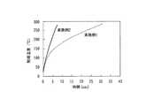
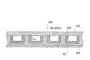
比較例では、図17に示された反応容器本体600を用いて電熱膜601で加熱した場合に、加熱開始時刻からの時間と触媒膜609の温度との関係をシミュレーションによって求めた。反応容器本体600は、図10、図11に示す反応容器本体550の電熱膜551と同様の電熱膜601をマイクロ流路606の葛折り状の溝606aの表面ではなく、第二基板604の下面側に配置させた以外は反応容器本体550と実質的に同様である。このため、葛折り状の溝606aには触媒膜609のみが成膜され、第二基板604の葛折り状の溝606aが形成された面を第一基板605で覆っている。シミュレーションの条件としては、電熱膜601の発熱量を20Wとし、第一基板54を熱伝導率148〔W/m・K〕、厚さ0.6mmのシリコン基板とし、第二基板55を熱伝導率1.3〔W/m・K〕、厚さ0.7mmのガラス基板とした。  In the comparative example, the relationship between the time from the heating start time and the temperature of thecatalyst film 609 was obtained by simulation when theelectrothermal film 601 was heated using the reaction vesselmain body 600 shown in FIG. The reaction vesselmain body 600 has anelectric heating film 601 similar to theelectric heating film 551 of the reaction vesselmain body 550 shown in FIGS. 10 and 11, not the surface of thetwisted groove 606 a of themicrochannel 606, but the lower surface of thesecond substrate 604. Thereaction vessel body 550 is substantially the same as thereaction vessel body 550 except that it is disposed on the side. Therefore, only thecatalyst film 609 is formed in thetwisted groove 606a, and the surface of thesecond substrate 604 where thetwisted groove 606a is formed is covered with thefirst substrate 605. As simulation conditions, the heating value of theelectrothermal film 601 is 20 W, thefirst substrate 54 is a silicon substrate having a thermal conductivity of 148 [W / m · K] and a thickness of 0.6 mm, and thesecond substrate 55 is thermally conductive. The glass substrate had a rate of 1.3 [W / m · K] and a thickness of 0.7 mm.

実施例1と比較例のシミュレーション結果を図13に示す。図13において、横軸は加熱開始時刻からの時間を表し、縦軸は触媒膜59の温度を示す。図13からわかるように、実施例1は比較例よりも触媒膜の温度が上昇しやすい。  The simulation results of Example 1 and the comparative example are shown in FIG. In FIG. 13, the horizontal axis represents the time from the heating start time, and the vertical axis represents the temperature of thecatalyst film 59. As can be seen from FIG. 13, in Example 1, the temperature of the catalyst membrane is more likely to rise than in the comparative example.

実施例2では、図8に示された反応容器本体350を用いて電熱膜351で加熱した場合に、加熱開始時刻からの時間と触媒膜359の温度との関係をシミュレーションによって求めた。シミュレーションの条件としては、電熱膜351の発熱量を10Wとし、第一基板354を熱伝導率1.3〔W/m・K〕、厚さ0.7mmのガラス基板とし、第二基板355を熱伝導率1.3〔W/m・K〕、厚さ0.7mmのガラス基板とし、第三基板370を熱伝導率1.3〔W/m・K〕、厚さ0.7mmのガラス基板とした。ここで、第二基板355をシリコン基板からガラス基板とすることによって基板自体の熱容量が小さくなるので、基板での熱のロスが少なくなり、迅速に触媒温度の高くすることができる。  In Example 2, when theelectrothermal film 351 was heated using the reaction vesselmain body 350 shown in FIG. 8, the relationship between the time from the heating start time and the temperature of thecatalyst film 359 was obtained by simulation. As conditions for the simulation, the heating value of theelectrothermal film 351 is 10 W, thefirst substrate 354 is a glass substrate having a thermal conductivity of 1.3 [W / m · K] and a thickness of 0.7 mm, and thesecond substrate 355 is A glass substrate having a thermal conductivity of 1.3 [W / m · K] and a thickness of 0.7 mm is used, and thethird substrate 370 is a glass having a thermal conductivity of 1.3 [W / m · K] and a thickness of 0.7 mm. A substrate was used. Here, since the heat capacity of the substrate itself is reduced by changing thesecond substrate 355 from a silicon substrate to a glass substrate, heat loss at the substrate is reduced, and the catalyst temperature can be quickly increased.

実施例2と実施例1のシミュレーション結果を図14に示す。図14において、横軸は加熱開始時刻からの時間を表し、縦軸は触媒膜の温度を示す。図14からわかるように、実施例2のガラス基板は、実施例1のシリコン基板からなる第二基板355よりも厚いにも関わらず熱容量が小さいため触媒膜の温度が上昇しやすい。  The simulation results of Example 2 and Example 1 are shown in FIG. In FIG. 14, the horizontal axis represents the time from the heating start time, and the vertical axis represents the temperature of the catalyst membrane. As can be seen from FIG. 14, although the glass substrate of Example 2 is thicker than thesecond substrate 355 made of the silicon substrate of Example 1, the temperature of the catalyst film is likely to rise because the heat capacity is small.

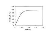
実施例3では、図4、図5に示された反応容器本体50を電熱膜51で加熱した場合に、加熱開始時刻からの時間と、切欠き58aで形成された流出口における各種気体の濃度との関係をシミュレーションによって求め、その結果を図15に示した。また、加熱開始時刻からの時間と、流出口におけるメタノール転化率との関係をシミュレーションによって求め、その結果を図16に示した。シミュレーションの条件としては、チャンバー56の大きさは幅を17〔mm〕とし、長さを20〔mm〕とし、深さを1.2〔mm〕とし、燃料9のスチームカーボン比を1.2とした。スチームカーボン比とは、原料炭化水素(ここでは、燃料9のメタノール)中の炭素原子に対する改質スチームの水分子の比を言い、H2O/Cで表される。図15において、横軸は加熱開始時刻からの時間を表し、縦軸は各種気体の濃度を表す。図16において、横軸は加熱開始時刻からの時間を表し、縦軸はメタノール転化率を表す。In Example 3, when the reaction vesselmain body 50 shown in FIGS. 4 and 5 is heated by theelectrothermal film 51, the time from the heating start time and the concentration of various gases at the outlet formed by thenotch 58a. The relationship is obtained by simulation, and the result is shown in FIG. Moreover, the relationship between the time from the heating start time and the methanol conversion rate at the outlet was determined by simulation, and the results are shown in FIG. The simulation conditions are as follows: thechamber 56 has a width of 17 [mm], a length of 20 [mm], a depth of 1.2 [mm], and a steam carbon ratio of thefuel 9 of 1.2. It was. The steam carbon ratio is a ratio of water molecules of the reformed steam to carbon atoms in the raw material hydrocarbon (here, methanol of the fuel 9), and is represented by H2 O / C. In FIG. 15, the horizontal axis represents the time from the heating start time, and the vertical axis represents the concentration of various gases. In FIG. 16, the horizontal axis represents the time from the heating start time, and the vertical axis represents the methanol conversion rate.

燃料電池式発電システムの燃料貯蔵モジュール及び発電モジュールを一部破断して示した斜視図である。It is the perspective view which partially cut and showed the fuel storage module and power generation module of a fuel cell type power generation system.上記燃料電池式発電システムの基本構成を示したブロック図である。It is the block diagram which showed the basic composition of the said fuel cell type electric power generation system.上記発電モジュールに内蔵された小型改質装置を一部破断して示した側面図である。It is the side view which fractured | ruptured and showed the small reformer built in the said electric power generation module.蒸発器、改質反応器、水性シフト反応器及び選択酸化反応器の反応容器本体を示した斜視図である。It is the perspective view which showed the reaction container main body of an evaporator, a reforming reactor, an aqueous shift reactor, and a selective oxidation reactor.図4に示されたV-V線に沿った断面図である。FIG. 5 is a cross-sectional view taken along line VV shown in FIG. 4.図4に示された反応容器本体とは別の反応容器本体を示した斜視図である。It is the perspective view which showed the reaction container main body different from the reaction container main body shown by FIG.図4、図6に示された反応容器本体とは別の反応容器本体を示した斜視図である。It is the perspective view which showed the reaction container main body different from the reaction container main body shown by FIG. 4, FIG.図4、図6、図7に示された反応容器本体とは別の反応容器本体を示した断面図である。It is sectional drawing which showed the reaction container main body different from the reaction container main body shown by FIG.4, FIG.6, FIG.7.図4、図6、図7、図8に示された反応容器本体とは別の反応容器本体を示した断面図である。It is sectional drawing which showed the reaction container main body different from the reaction container main body shown by FIG.4, FIG.6, FIG.7 and FIG.図4、図6、図7、図8、図9に示された反応容器本体とは別の反応容器本体を示した斜視図である。FIG. 10 is a perspective view showing a reaction vessel body different from the reaction vessel body shown in FIGS. 4, 6, 7, 8, and 9.図10に示されたXI-XI線に沿った断面図である。It is sectional drawing along the XI-XI line | wire shown by FIG.反応時間と拡散時間の比と、メタノール転化率との関係を示したグラフである。It is the graph which showed the relationship between ratio of reaction time and diffusion time, and methanol conversion.実施例1において加熱時間と触媒膜の温度との関係を示したグラフである。4 is a graph showing a relationship between a heating time and a temperature of a catalyst film in Example 1.実施例1及び実施例2において加熱時間と触媒膜の温度との関係を示したグラフである。6 is a graph showing the relationship between the heating time and the temperature of the catalyst film in Example 1 and Example 2.実施例3において加熱時間と各種気体の濃度との関係を示したグラフである。6 is a graph showing the relationship between the heating time and the concentrations of various gases in Example 3.実施例3において加熱時間とメタノール転化率との関係を示したグラフである。4 is a graph showing the relationship between heating time and methanol conversion rate in Example 3.比較例として用いた反応容器本体を示した断面図である。It is sectional drawing which showed the reaction container main body used as a comparative example.

符号の説明Explanation of symbols

40 … 改質装置
41 … 蒸発器(反応器)
42 … 改質反応器(反応器)
43 … 水性シフト反応器(反応器)
44 … 選択酸化反応器(反応器)
50、150、250、350、450、550 … 反応容器本体
51、351、451、551 … 電熱膜
54、354、454、554 … 第一基板
55、355、455、555 … 第二基板
56、156、256、356、456 … チャンバー(内部空間)
59 … 触媒膜
556 … マイクロ流路(内部空間)
40 ...reformer 41 ... evaporator (reactor)
42 ... Reforming reactor (reactor)
43… Aqueous shift reactor (reactor)
44… Selective oxidation reactor (reactor)
50, 150, 250, 350, 450, 550... Reaction vesselmain bodies 51, 351, 451, 551...Electrothermal films 54, 354, 454, 554...First substrate 55, 355, 455, 555. 256, 356, 456 ... chamber (internal space)
59 ...Catalyst membrane 556 ... Micro flow path (internal space)

Claims (8)

Translated fromJapanese
反応物が供給される内部空間を形成した反応容器本体と、前記内部空間の壁面に成膜された電熱膜と、前記電熱膜に積層された触媒膜と、を具備することを特徴とする反応器。  A reaction vessel body having an internal space to which a reactant is supplied; an electrothermal film formed on a wall surface of the internal space; and a catalyst film laminated on the electrothermal film. vessel. 前記触媒膜の熱伝導率が前記反応容器本体の熱伝導率よりも高いことを特徴とする請求項1に記載の反応器。  The reactor according to claim 1, wherein the thermal conductivity of the catalyst film is higher than the thermal conductivity of the reaction vessel main body. 前記内部空間が六面体状の空間であることを特徴とする請求項1又は2に記載の反応器。  The reactor according to claim 1 or 2, wherein the internal space is a hexahedral space. 前記内部空間が流路状の空間であり、その内部空間の深さをdchaとし、前記触媒膜の膜厚をdcatとした場合、次式(C)を満たすことを特徴とする請求項1又は2に記載の反応器。
Figure 2005087803
The internal space is a channel-shaped space, and when the depth of the internal space is dcha and the film thickness of the catalyst film is dcat , the following equation (C) is satisfied: The reactor according to 1 or 2.
Figure 2005087803
前記反応物がメタノールと水との混合気であり、前記触媒膜がメタノールと水を水素と二酸化炭素に改質する性質を有することを特徴とする請求項1から4の何れか一項に記載の反応器。  5. The reaction product according to claim 1, wherein the reactant is a mixture of methanol and water, and the catalyst film has a property of reforming methanol and water into hydrogen and carbon dioxide. Reactor. 前記触媒膜には、Cu/Zn系触媒が含まれていることを特徴とする請求項5に記載の反応器。  The reactor according to claim 5, wherein the catalyst film contains a Cu / Zn-based catalyst. 反応物が供給される内部空間を形成した反応容器本体を具備し、
前記内部空間が流路状の空間であり、前記内部空間の深さ、長さをそれぞれdcha、Lchaとし、前記内部空間を流れる流体の平均流速、有効拡散係数をそれぞれv、Dmとした場合、次式(A)を満たすことを特徴とする反応器。
Figure 2005087803
Comprising a reaction vessel body having an internal space to which reactants are supplied;
The internal space is a channel-like space, the depth and length of the internal space are dcha and Lcha , respectively, and the average flow velocity and effective diffusion coefficient of the fluid flowing through the internal space are v and Dm , respectively. In that case, the reactor satisfies the following formula (A).
Figure 2005087803
反応物が供給される内部空間面に露出された触媒膜が形成された反応容器本体を具備し、
前記内部空間が流路状の空間であり、前記触媒膜の厚さ、前記内部空間の長さをそれぞれdcha、Lchaとし、前記内部空間を流れる流体の平均流速、有効拡散係数をそれぞれv、DeAとした場合、次式(B)を満たすことを特徴とする反応器。
Figure 2005087803
Comprising a reaction vessel main body formed with a catalyst film exposed on the inner space to which the reactant is supplied;
The internal space is a channel-like space, and the thickness of the catalyst membrane and the length of the internal space are dcha and Lcha , respectively, and the average flow velocity and effective diffusion coefficient of the fluid flowing through the internal space are v , DeA , a reactor satisfying the following formula (B):
Figure 2005087803
JP2003321812A2003-09-122003-09-12 ReactorExpired - Fee RelatedJP4961657B2 (en)

Priority Applications (1)

Application NumberPriority DateFiling DateTitle
JP2003321812AJP4961657B2 (en)2003-09-122003-09-12 Reactor

Applications Claiming Priority (1)

Application NumberPriority DateFiling DateTitle
JP2003321812AJP4961657B2 (en)2003-09-122003-09-12 Reactor

Publications (2)

Publication NumberPublication Date
JP2005087803Atrue JP2005087803A (en)2005-04-07
JP4961657B2 JP4961657B2 (en)2012-06-27

Family

ID=34453374

Family Applications (1)

Application NumberTitlePriority DateFiling Date
JP2003321812AExpired - Fee RelatedJP4961657B2 (en)2003-09-122003-09-12 Reactor

Country Status (1)

CountryLink
JP (1)JP4961657B2 (en)

Cited By (9)

* Cited by examiner, † Cited by third party
Publication numberPriority datePublication dateAssigneeTitle
JP2007099596A (en)*2005-10-072007-04-19Ishikawajima Shibaura Mach Co LtdFuel modification device
WO2008026656A1 (en)*2006-08-302008-03-06Kyocera CorporationReaction device, fuel battery system, and electronic device
JP2008056527A (en)*2006-08-302008-03-13Kyocera Corp Reactor, fuel cell system and electronic device
JP2008059872A (en)*2006-08-302008-03-13Kyocera Corp Reactor, fuel cell system and electronic device
JP2008059871A (en)*2006-08-302008-03-13Kyocera Corp Reactor, fuel cell system and electronic device
JP2008308382A (en)*2007-06-182008-12-25Casio Comput Co Ltd Reactor, power generator and electronic equipment
JP2010059050A (en)*2008-09-052010-03-18Samsung Sdi Co LtdEvaporator and fuel reformer
US8382865B2 (en)2006-08-302013-02-26Kyocera CorporationReaction apparatus, fuel cell system and electronic device
WO2019122101A1 (en)*2017-12-212019-06-27Hte Gmbh The High Throughput Experimentation CompanyReactor system for continuous flow reactions

Citations (8)

* Cited by examiner, † Cited by third party
Publication numberPriority datePublication dateAssigneeTitle
JP2001185195A (en)*1999-12-282001-07-06Mitsubishi Gas Chem Co Inc Method for producing hydrogen for fuel cells
JP2001322283A (en)*1999-05-132001-11-20Casio Comput Co LtdHeating resistor and method of its production
JP2002003203A (en)*2000-06-202002-01-09Suzuki Motor CorpMethod for manufacturing methanol reforming apparatus
JP2003045459A (en)*2001-08-012003-02-14Casio Comput Co Ltd Heating device, reformer, and fuel cell system
JP2003088754A (en)*2001-09-182003-03-25Casio Comput Co Ltd Chemical reaction apparatus and control method thereof
JP2003095614A (en)*2001-09-182003-04-03Toshiba International Fuel Cells CorpApparatus for producing hydrogen
JP2003226657A (en)*2001-11-202003-08-12Rohm & Haas CoElectroactive catalysis
JP2004518598A (en)*2000-08-282004-06-24モトローラ・インコーポレイテッド Hydrogen generator using ceramic technology

Patent Citations (8)

* Cited by examiner, † Cited by third party
Publication numberPriority datePublication dateAssigneeTitle
JP2001322283A (en)*1999-05-132001-11-20Casio Comput Co LtdHeating resistor and method of its production
JP2001185195A (en)*1999-12-282001-07-06Mitsubishi Gas Chem Co Inc Method for producing hydrogen for fuel cells
JP2002003203A (en)*2000-06-202002-01-09Suzuki Motor CorpMethod for manufacturing methanol reforming apparatus
JP2004518598A (en)*2000-08-282004-06-24モトローラ・インコーポレイテッド Hydrogen generator using ceramic technology
JP2003045459A (en)*2001-08-012003-02-14Casio Comput Co Ltd Heating device, reformer, and fuel cell system
JP2003088754A (en)*2001-09-182003-03-25Casio Comput Co Ltd Chemical reaction apparatus and control method thereof
JP2003095614A (en)*2001-09-182003-04-03Toshiba International Fuel Cells CorpApparatus for producing hydrogen
JP2003226657A (en)*2001-11-202003-08-12Rohm & Haas CoElectroactive catalysis

Cited By (11)

* Cited by examiner, † Cited by third party
Publication numberPriority datePublication dateAssigneeTitle
JP2007099596A (en)*2005-10-072007-04-19Ishikawajima Shibaura Mach Co LtdFuel modification device
WO2008026656A1 (en)*2006-08-302008-03-06Kyocera CorporationReaction device, fuel battery system, and electronic device
JP2008056527A (en)*2006-08-302008-03-13Kyocera Corp Reactor, fuel cell system and electronic device
JP2008059872A (en)*2006-08-302008-03-13Kyocera Corp Reactor, fuel cell system and electronic device
JP2008059871A (en)*2006-08-302008-03-13Kyocera Corp Reactor, fuel cell system and electronic device
US8382865B2 (en)2006-08-302013-02-26Kyocera CorporationReaction apparatus, fuel cell system and electronic device
US8382866B2 (en)2006-08-302013-02-26Kyocera CorporationReaction apparatus, fuel cell system and electronic device
JP2008308382A (en)*2007-06-182008-12-25Casio Comput Co Ltd Reactor, power generator and electronic equipment
JP2010059050A (en)*2008-09-052010-03-18Samsung Sdi Co LtdEvaporator and fuel reformer
US8568495B2 (en)2008-09-052013-10-29Samsung Sdi Co., Ltd.Evaporator and fuel reformer having the same
WO2019122101A1 (en)*2017-12-212019-06-27Hte Gmbh The High Throughput Experimentation CompanyReactor system for continuous flow reactions

Also Published As

Publication numberPublication date
JP4961657B2 (en)2012-06-27

Similar Documents

PublicationPublication DateTitle
AU2003269498B2 (en)Chemical reactor and fuel cell system
US7175817B2 (en)Compact chemical reactor and chemical reaction system
US7410515B2 (en)Reformer, method for manufacturing the reformer, and power generation system
JP3873171B2 (en) Reforming apparatus and power generation system
JP4961657B2 (en) Reactor
WO2005030384A1 (en)Thermal treatment apparatus and power generation module
JP4269742B2 (en) Method for producing catalytic reactor and catalytic reactor
JP2005103399A (en) Reaction apparatus and reaction method
JP2004281340A (en) Fuel container
KR100804913B1 (en) Reactor
JP4453261B2 (en) Fuel supply mechanism
JP4665803B2 (en) Reactor
JP4269743B2 (en) Method for producing catalytic reactor
JP4371093B2 (en) Reactor
JP4386018B2 (en) Reactor
JP4590928B2 (en) Vaporizer
JP4380612B2 (en) Reactor
JP2004290880A (en) Small reactor
JP2007015920A (en) Reforming apparatus and power generation system
JP4380613B2 (en) Reactor
JP2007268531A (en) Small chemical reactor
JP2011000586A (en)Reactor
JP2008238028A (en) Reactor
JP2005259453A (en) Power generation device and fuel storage module

Legal Events

DateCodeTitleDescription
A621Written request for application examination

Free format text:JAPANESE INTERMEDIATE CODE: A621

Effective date:20060904

A977Report on retrieval

Free format text:JAPANESE INTERMEDIATE CODE: A971007

Effective date:20081121

A131Notification of reasons for refusal

Free format text:JAPANESE INTERMEDIATE CODE: A131

Effective date:20100105

A521Request for written amendment filed

Free format text:JAPANESE INTERMEDIATE CODE: A523

Effective date:20100305

A131Notification of reasons for refusal

Free format text:JAPANESE INTERMEDIATE CODE: A131

Effective date:20110329

A521Request for written amendment filed

Free format text:JAPANESE INTERMEDIATE CODE: A523

Effective date:20110527

RD02Notification of acceptance of power of attorney

Free format text:JAPANESE INTERMEDIATE CODE: A7422

Effective date:20110527

TRDDDecision of grant or rejection written
A01Written decision to grant a patent or to grant a registration (utility model)

Free format text:JAPANESE INTERMEDIATE CODE: A01

Effective date:20120228

A01Written decision to grant a patent or to grant a registration (utility model)

Free format text:JAPANESE INTERMEDIATE CODE: A01

A61First payment of annual fees (during grant procedure)

Free format text:JAPANESE INTERMEDIATE CODE: A61

Effective date:20120312

R150Certificate of patent or registration of utility model

Free format text:JAPANESE INTERMEDIATE CODE: R150

FPAYRenewal fee payment (event date is renewal date of database)

Free format text:PAYMENT UNTIL: 20150406

Year of fee payment:3

LAPSCancellation because of no payment of annual fees

[8]ページ先頭

©2009-2025 Movatter.jp