JP2005087477A - Internal hemorrhoid suction rubber band ligator - Google Patents
Internal hemorrhoid suction rubber band ligatorDownload PDFInfo
- Publication number
- JP2005087477A JP2005087477AJP2003324781AJP2003324781AJP2005087477AJP 2005087477 AJP2005087477 AJP 2005087477AJP 2003324781 AJP2003324781 AJP 2003324781AJP 2003324781 AJP2003324781 AJP 2003324781AJP 2005087477 AJP2005087477 AJP 2005087477A
- Authority
- JP
- Japan
- Prior art keywords
- cylinder
- inner cylinder
- outer cylinder
- suction
- rubber
- Prior art date
- Legal status (The legal status is an assumption and is not a legal conclusion. Google has not performed a legal analysis and makes no representation as to the accuracy of the status listed.)
- Pending
Links
- 201000007772internal hemorrhoidDiseases0.000titleclaimsabstractdescription18
- 208000014617hemorrhoidDiseases0.000claimsdescription34
- 230000003014reinforcing effectEffects0.000claimsdescription16
- 229920005989resinPolymers0.000claimsdescription14
- 239000011347resinSubstances0.000claimsdescription14
- 230000002093peripheral effectEffects0.000claimsdescription12
- 238000005286illuminationMethods0.000claimsdescription10
- 238000003780insertionMethods0.000claimsdescription9
- 230000037431insertionEffects0.000claimsdescription9
- 230000008878couplingEffects0.000claimsdescription8
- 238000010168coupling processMethods0.000claimsdescription8
- 238000005859coupling reactionMethods0.000claimsdescription8
- 239000000463materialSubstances0.000claimsdescription3
- 230000001678irradiating effectEffects0.000claims1
- 238000000465mouldingMethods0.000description13
- 238000011282treatmentMethods0.000description7
- 238000004519manufacturing processMethods0.000description5
- 230000033001locomotionEffects0.000description4
- 210000003813thumbAnatomy0.000description4
- 238000000034methodMethods0.000description3
- 244000052616bacterial pathogenSpecies0.000description2
- 210000003811fingerAnatomy0.000description2
- 229920003023plasticPolymers0.000description2
- 238000002560therapeutic procedureMethods0.000description2
- 230000005540biological transmissionEffects0.000description1
- 230000000740bleeding effectEffects0.000description1
- 230000007423decreaseEffects0.000description1
- 230000009545invasionEffects0.000description1
- 238000005304joiningMethods0.000description1
- 230000013011matingEffects0.000description1
- 239000002184metalSubstances0.000description1
- 239000002674ointmentSubstances0.000description1
- 239000004033plasticSubstances0.000description1
- 238000003825pressingMethods0.000description1
- 238000002271resectionMethods0.000description1
- 238000007632sclerotherapyMethods0.000description1
- 238000001356surgical procedureMethods0.000description1
- 208000024891symptomDiseases0.000description1
- 229920003002synthetic resinPolymers0.000description1
- 239000000057synthetic resinSubstances0.000description1
- 230000001225therapeutic effectEffects0.000description1
Images


Landscapes
- Surgical Instruments (AREA)
Abstract
Description
Translated fromJapanese本発明は、内痔核処置用器具に関し、特に、内痔核を輪ゴムで結紮するための内痔核吸引輪ゴム結紮器に関する。 The present invention relates to an internal hemorrhoid treatment instrument, and more particularly, to an internal hemorrhoid suction rubber band ligator for ligating an internal hemorrhoid with a rubber band.
従来、内痔核の治療は、その症状が軽度から重度になるにしたがって、1度、2度、3度、…のように分類され、1度は軟膏などを用いた保存的治療を、また、2度は硬化療法や輪ゴム結紮療法などの外来治療を行い、さらに、3度以上の内痔核や1度あるいは2度でも出血を繰り返すような症例に対しては結紮切除術を主とした手術を行うのが一般的である。 Conventionally, the treatment of internal hemorrhoids is classified as once, twice, three times, etc. according to the symptom becoming mild to severe, and conservative treatment using ointment etc. once, Perform outpatient treatments such as sclerotherapy and rubber band ligation therapy twice, and surgery for ligation and resection for cases with internal hemorrhoids more than 3 times and bleeding once or twice It is common to do it.
これらの治療方法のうち、輪ゴム結紮療法には、内痔核を輪ゴムで結紮する器具が用いられていた。この器具は、本発明者の一人により発明されたものであり、内痔核を軸方向にスライド可能に同心的に配置された内外二重筒を介して空気流により吸引し、内筒先端に装着された輪ゴムを外筒のスライドにより、内痔核に移動させ、結紮するものである(特許文献1)。
しかし、上記の内痔核吸引輪ゴム結紮器は、雑菌の侵入、患者間の病原菌の伝染等、衛生上の観点から、一度使用した器具は使い捨てとすることが望ましい。しかし従来の内痔核吸引輪ゴム結紮器はその構造が複雑であり、量産に適していないため、その製造コストが高く、使い捨てにすることは困難であった。 However, it is desirable that the above-mentioned inner hemorrhoid suction ring rubber ligator be disposable once used from the viewpoint of hygiene such as invasion of germs and transmission of pathogenic bacteria between patients. However, since the conventional inner core suction ring rubber ligator has a complicated structure and is not suitable for mass production, its production cost is high and it is difficult to make it disposable.
そこで、本発明の目的は、量産に適した構造を備え、安価で使い捨てが可能であるとともに、操作性の優れた内痔核吸引輪ゴム結紮器を提供することにある。 SUMMARY OF THE INVENTION An object of the present invention is to provide an inner core suction ring rubber ligator having a structure suitable for mass production, being inexpensive and disposable, and having excellent operability.
本発明の内痔核吸引輪ゴム結紮器は、左右に移動し、その端部近辺にバネ止め部を有する外筒と、その外筒内部に内包され且つ端部に注視鏡が、また、その端部近辺に吸引調整孔を有し、且つ内部で中空状態で連結している吸引調整筒を備えた内筒と、前記外筒の左右移動を行う引き金と、前記外筒に取り付けられていて、この引き金の操作によって前記外筒の左右移動を調整するように前記外筒に取り付けられていてバネと、前記内筒と一体的に固定連結されていて、その上部に照明灯を装着する照明灯装着部が、また、下部に吸引チューブを挿入するチューブ差込み部がそれぞれ設けられている握り部とを備えたことを特徴とするものである。 An inner hemorrhoid suction ring rubber ligator according to the present invention moves left and right and has an outer cylinder having a spring stopper in the vicinity of the end thereof, a gazescope included in the outer cylinder and a gazescope at the end, and an end thereof. An inner cylinder provided with a suction adjustment cylinder having a suction adjustment hole in the vicinity and connected in a hollow state inside, a trigger for moving the outer cylinder to the left and right, and attached to the outer cylinder. Attached to the outer cylinder so as to adjust the left / right movement of the outer cylinder by the operation of a trigger, and attached to the spring, and an illuminating lamp that is fixedly connected integrally with the inner cylinder, and an illuminating lamp is mounted on the upper part thereof The portion further includes a grip portion provided with a tube insertion portion for inserting the suction tube at a lower portion.
また、本発明の内痔核吸引輪ゴム結紮器においては、前記吸引調整筒は前記握り部の左右側面に突出していることを特徴とするものである。 In the inner hemorrhoid suction ring rubber ligator according to the present invention, the suction adjusting cylinder protrudes from the left and right side surfaces of the grip portion.
さらに、本発明の内痔核吸引輪ゴム結紮器においては、前記内筒に装着自在で、且つ先端が細く円錐形に形成されている輪ゴム装着補助器を備えたことを特徴とするものである。 Furthermore, in the inner hemorrhoid suction rubber band ligator of the present invention, there is provided a rubber band mounting auxiliary device that can be mounted on the inner cylinder and has a thin tip and a conical shape.
さらに、本発明の内痔核吸引輪ゴム結紮器においては、前記照明灯装着部の上部は、前記外筒の先端前方を照らすように、その先端方向が後部よりも低い傾斜をもって形成されていることを特徴とするものである。 Furthermore, in the inner hemorrhoid suction ring rubber ligator of the present invention, the upper part of the illuminating lamp mounting part is formed such that the tip direction thereof is inclined with a lower slope than the rear part so as to illuminate the front end of the outer cylinder. It is a feature.
さらに、本発明の内痔核吸引輪ゴム結紮器においては、前記輪ゴム装着補助器には、その先端部分が複数の輪ゴムが装着できる長さを有していることを特徴とするものである。 Further, in the inner hemorrhoid suction rubber band ligator according to the present invention, the rubber band attachment assisting device has a length that allows a plurality of rubber bands to be attached at a tip portion thereof.
さらに、本発明の内痔核吸引輪ゴム結紮器においては、前記外筒および前記内筒と、前記吸引調整筒および前記引き金ならびに前記握り部とは、透明プラスチック材で形成されていることを特徴とするものである。 Furthermore, in the inner hemorrhoid suction ring rubber ligator according to the present invention, the outer cylinder and the inner cylinder, the suction adjustment cylinder, the trigger, and the grip portion are formed of a transparent plastic material. Is.
さらに、本発明の内痔核吸引輪ゴム結紮器においては、上部に照明灯装着部を、また、その上部側面には吸引調整筒を突出させる突出穴を有し、さらに、下部にはチューブ差込部材を取り付ける差込部材取付け穴を有し、且つその裏面内部に両者を合体させる合体手段と引き金挿入突起部とを有する左右握り部と、右端近辺にバネ止めと、そのバネ止めの右側下部に設けた噛合い歯とを有する外筒と、この外筒内部に挿入され、且つその右端近辺には吸引調整孔を有して内部で中空状態で連結している前記吸引調整筒と前記左右握り部を固定する握手固定部材とを有する内筒と、この内筒に対する外筒の移動を調整するバネと、上部に前記噛合い歯と噛合う引き金歯および挿入孔を有する引き金とを備え、前記外筒の右端からバネを挿入した後、前記内筒を前記外筒に挿入し、さらに、前記引き金歯を前記噛合い歯に噛み合わせた状態で前記引き金を前記左右握り部に合体させ、さらに、その左右握り部側面から突出穴を介して吸引調整筒を外部に突出させて前記握手固定部材に前記左右握り部を固定したことを特徴とするものである。 Furthermore, in the internal hemorrhoid suction ring rubber ligator according to the present invention, the upper part has an illumination lamp mounting part, the upper side surface has a projecting hole for projecting the suction adjusting cylinder, and the lower part has a tube insertion member Left and right gripping parts having a uniting means for joining the two and a trigger insertion projection part inside the back surface, a spring stopper near the right end, and a lower right part of the spring stopper. An outer cylinder having meshing teeth, and the suction adjustment cylinder inserted into the outer cylinder and having a suction adjustment hole near the right end thereof and connected in a hollow state inside and the left and right grips An inner cylinder having a handshake fixing member for fixing the outer cylinder, a spring for adjusting the movement of the outer cylinder relative to the inner cylinder, a trigger tooth having an engagement hole and an insertion hole engaging with the meshing tooth on the upper part, and the outer cylinder A spring was inserted from the right end of the tube The inner cylinder is inserted into the outer cylinder, and the trigger is combined with the left and right grips in a state where the trigger teeth are engaged with the meshing teeth, and a protruding hole is further formed from the side surface of the left and right grips. The left and right grip portions are fixed to the handshake fixing member by projecting the suction adjustment cylinder to the outside.
上記した本発明によれば、小型軽量であり、かつ、機械的強度も高く、安価で使い捨て使用が可能であり、したがって衛生的な内痔核吸引輪ゴム結紮器が得られる。 According to the present invention described above, it is small and light, has high mechanical strength, is inexpensive and can be used in a disposable manner, and thus a hygienic inner core suction ring rubber ligator can be obtained.
さらに、本発明によれば、輪ゴム装着補助器あるいは照明灯を併用することによって、より高い治療効果が得られる。 Furthermore, according to the present invention, a higher therapeutic effect can be obtained by using a rubber band wearing aid or an illuminating lamp together.
以下、本発明の実施形態を図面により詳細に説明する。 Hereinafter, embodiments of the present invention will be described in detail with reference to the drawings.
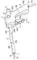
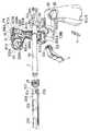
図1は、本発明による内痔核吸引輪ゴム結紮器の斜視図であり、図2はその分解斜視図である。この内痔核吸引輪ゴム結紮器は、全体としてピストル型をしており、内筒1が外筒2内に挿入されている。すなわち、内筒1および外筒2は、互いに軸方向にスライド可能に同心的に配置された二重筒からなり、内筒1は、引き金3が矢示4方向に引かれると、外筒2内に引き込まれるように構成されている。外筒2の後端には、内筒1の内部を通して患部(不図示)を拡大して観察できる拡大レンズ5が取り付けられている。FIG. 1 is a perspective view of an inner hemorrhoid suction ring rubber ligator according to the present invention, and FIG. 2 is an exploded perspective view thereof. This internal hemorrhoid suction ring rubber ligator has a pistol type as a whole, and the
また、握り部6は内筒1が挿入された外筒2を支持する支持部601と、この支持部601に一体的に形成され、前記筒軸に交差する方向に延長された把持部602から構成されている。支持部601は、外筒2をその後端部において支持するために、外筒2の筒軸に沿って延長され、外筒2の外周をほぼ同軸的に包囲するように形成されている。また、把持部602は、支持部601の後端部において前記筒軸に交差する方向に延長され、器具の使用者が片手で把持できるような大きさに形成されている。 The
握り部6の支持部601上部には、外筒2の筒軸に沿い、かつ、外筒2の前方に向かって徐々に高さが低下する斜面を有する照明灯装着部7が設けられている。この照明灯装着部7には、後述する照明灯を装着すると、その照明光が外筒2の先端部に位置する患部を照射するようになっている。 On the upper portion of the
さらに、握り部6の側面両側には、内部で内筒1と連結する吸引調整筒8を外部に導出するための透孔9が設けられている。この吸引調整筒8は、器具の使用者が握り部6を握りながら、例えば、その握り手の親指でこれを塞いだり開放したりすることによって内筒1による吸引の開始・停止あるいは吸引の強さを調整するためのものである。 Furthermore, through
さらに、握り部6の下部には、吸引ポンプ(図示せず。)に接続された吸引管10が接続される接続栓11が取り付けられている。 Further, a
図2および図3により上記内痔核吸引輪ゴム結紮器の内部構造についてさらに説明する。 The internal structure of the inner hemorrhoid suction ring rubber ligator will be further described with reference to FIGS.
内筒1は、図2および図4に示されるように、その中央の外周面に径が幾分縮小された径小部101が形成され、外筒2との軸方向のスライド抵抗を減少させている。内筒1は、その後端部に外筒2の内径よりやや大きな径を有する径大部102が形成されている。この径大部102には、上述した吸引調整筒8が、内筒1の半径方向で反対側にそれぞれ延長配置されている。図2および図4では両側の吸引調整筒をそれぞれ8A、8Bで示している。これらの吸引調整筒8A、8Bはそれぞれその開口端が斜めに切断された形状になっており、親指で開口端を開閉しやすくなっている。内筒1の径大部102にはまた、内筒1の軸に沿って固定板103、104が半径方向で反対側にそれぞれ配置されている。これらの固定板103A、103Bにはそれぞれ複数個の固定孔105が形成されている。このような内筒1は、樹脂成形により製造することが可能である。 As shown in FIGS. 2 and 4, the
内筒1の径大部102にはさらに、図2および図4(B)に示されるように、吸引用のチューブを接続するための樹脂製の第1の接続栓106が内筒1の外周面上に設けられている。第1の接続栓106は、後述するように、この接続栓106に接続される吸引用のチューブを介して、内筒1内の空気を吸引するために設けられている。図4(C)は、内筒1をその後端側から見た背面図である。同図のように内筒1の外周面上において、吸引調整筒8A、8Bは水平方向に延長され、接続栓106は垂直方向に延長されている。 As shown in FIGS. 2 and 4B, the
次に、外筒2は、図1あるいは図2に示されるように、その円周面上の上下部分において、軸方向に複数本の長孔201、202、203が形成されている。これらの長孔201、202、203は、内筒1とのスライド抵抗を減少するために形成されている。外筒2の後端部外周面には、その後端から見て上部および左右に3個のバネ係止用突起204、205、206が設けられている。そして外筒2の後端部外周面下側には、平面歯車207を構成する歯列が軸に沿って形成されている。この平面歯車207は、後述するように、引き金3の回動により、外筒2をその軸方向に移動させるために用いられる。このような外筒2も樹脂成形により製造することが可能である。 Next, as shown in FIG. 1 or FIG. 2, the
図2に示される金属製のコイルスプリング21は、その内径が外筒2の外周よりやや大きく外筒2の外周に嵌合してその軸方向に移動するが、外筒2の外周に固定された3個のバネ係止用突起204、205、206によりその移動が阻止されるように構成されている。内筒1および外筒2に対してコイルスプリング21は次のように組み立てられる。まず、内筒1がその先端部から外筒2内に挿入される。この場合、内筒1は、外筒2の後端部が内筒1の径大部102前端部に接触するまで挿入される。その後、外筒2の先端部からコイルスプリング21が挿入され、バネ係止用突起204、205、206にその移動が阻止されるまで、外筒2の後端に向かって移動される。 The
次に、握り部6は、図2に示されるように、外筒2を両側から2個の半握り部6A、6Bにより挟んで支持するように構成されている。また、このように2個の半握り部6A、6Bを合体することにより構成される握り部6は、その内部が中空となるように、各半握り部6A、6Bを樹脂成型により製造される。 Next, as shown in FIG. 2, the
握り部6には、また、支持部601の前端部において、前記筒軸に沿って長孔603が形成され、この長孔603から引き金3が、把持部602にほぼ平行に突出している。この引き金3は同じく樹脂成形により製造され、図2に示されるように、その基部に回転軸受筒301が樹脂成形により設けられている。この回転軸受筒301には、半握り部6Aの内壁に一端が植設された樹脂製の筒状回転軸604Aが挿入され、引き金3はこの筒状回転軸604Aの周りに回動可能に支持される。引き金3の回転軸受筒301の周囲の外周面には、前述した外筒2の後端部に形成された平面歯車207に噛み合う円形歯車302が形成されている。 In the
半握り部6Bの内壁にも、図3(B)に示すように、回転軸604Aに対応して同様な回転軸604Bの一端が植設されており、半握り部6Bが半握り部6Aに合体されたとき、回転軸604Aおよび回転軸604Bは共に引き金3の回転軸受筒301内部に挿入され、両者で一体となって引き金3の回転軸を形成する。半握り部6Aに植設された回転軸604Aの周囲の内壁には、リング状の突起605Aが植設されており、このリング状の突起605A内には引き金3の回転軸受筒301の一端が嵌合する。すなわちこのリング状の突起605Aは、引き金3の回動の際、その回転を案内する機能を有している。半握り部6Bの内壁にも、図3(B)に示すように、同様なリング状の突起605Bが設けられている。 As shown in FIG. 3 (B), one end of a similar
半握り部6Aの内壁にはまた、図2に示されるように、外筒2を支持するとともに中空の握り部6の強度を補強するための第1の補強板606A、第2の補強板607Aが樹脂成形により固定されている。これらの補強板606A、607Aの上端には半円弧状の切欠部が形成され、これらの部分で外筒2の外周面を支持する。半握り部6Aの前壁608Aおよび後壁609Aにも同様な半円弧状の切欠部が形成され、これらの部分で外筒2の外周面を支持する。半握り部6Bにも、図3(B)に示すように、半握り部6Aとほぼ対照的な構造の補強板606A、607Aあるいは前壁608Bおよび後壁609Bを備えている。 As shown in FIG. 2, the inner wall of the
半握り部6Aの内壁にはさらに、図2あるいは図3(A)に示されるように、複数個の結合ロッド611A〜615Aがほぼ垂直に樹脂成形により植設されている。半握り部6Bの内壁には、図3(B)に示されるように、これらの結合ロッド611A〜615Aが圧入される複数個の結合筒体611B〜615B(図示せず。)が樹脂成形により植設されている。半握り部6Aと半握り部6Bとは、結合ロッド611A〜615Aが対応する結合筒体611B〜615Bに圧入されることによって、外筒2を挟んで一体に結合される。 Further, as shown in FIG. 2 or FIG. 3 (A), a plurality of connecting
また、半握り部6Aの内壁には図2あるいは図3(B)に示した内筒1の固定板103A、103Bに形成された複数個の固定孔105に挿入され、内筒1を握り部6内に固定するための、固定ピン616A、617A、618Aが樹脂成形により植設されている。半握り部6Bの内壁にも、対応する部分に固定ピン616B、617B、618Bが同様に植設されている。半握り部6Aと半握り部6Bとを内筒1を挟んで合体すると、それぞれの固定ピン616A、617A、618Aおよび固定ピン616B、617B、618Bは、内筒1の固定板103A、103Bに形成された複数個の固定孔105に両側から挿入され、内筒1を握り部6内に固定する。 Further, the inner wall of the
半握り部6Aの内壁において、把持部602に該当する部分にはさらに、図2あるいは図3(A)に示されるように、第3乃至第7の補強板620A〜624Aが樹脂成形により設けられている。これらのうち第3の補強板620Aは、第1および第2の補強板606A、607Aと同様に、外筒2の筒軸に対してほぼ直交する方向に延長配置されているが、第4乃至第7の補強板621A〜624Aは外筒2の筒軸に対してほぼ平行に延長配置されている。半握り部6Bにも図3(B)に示されるように、同様な第3乃至第7の補強板620B〜624Bが対称的に設けられている。 As shown in FIG. 2 or FIG. 3 (A), third to seventh reinforcing
半握り部6Aの支持部601の上面には図3(A)に示されるように、照明灯装着部7Aが樹脂成形により一体に設けられている。照明灯装着部7Aは内筒1の軸方向に平行に延長され、その後端部において開口する中空部7Cを有している。半握り部6Bにも図3(B)に示されるように、同様な照明灯装着部7Bが樹脂成形により設けられており、半握り部6Aと半握り部6Bを内筒1および外筒2を挟んで合体させたとき、照明灯装着部7Aおよび7Bも合体されて、照明灯装着部7を形成する。 As shown in FIG. 3A, an illumination
図5は図1に示した内痔核吸引輪ゴム結紮器の一部を分解して示す側面図である。同図においては、図1の構成部分と同一の部分には同一の符号を付して示し、重複した説明は行わないこととする。 FIG. 5 is an exploded side view showing a part of the inner hemorrhoid suction ring rubber ligator shown in FIG. In the figure, the same components as those shown in FIG. 1 are designated by the same reference numerals, and redundant description will not be given.
外筒2およびこの内部に挿入された内筒1は、握り部6の支持部601内に支持される。すなわち、外筒2は支持部601の前壁608A(608B)に設けられた開口608Cおよび第1の補強板606A(606B)に設けられた切欠部により支持される。また、内筒1は支持部601後壁609Aに設けられた開口609Cおよび第2の補強板607Aに設けられた切欠部により支持される。内筒1はさらに、その径大部102に固定された固定板103A、103Bに形成された複数個の固定孔105に、半握り部6Aに植設された固定ピン616A、617A、618Aおよび半握り部6Bに植設された固定ピン616B、617B、618Bを、固定板103A、103Bの両側から挿入することにより、握り部6内に固定される。 The
外筒2に嵌合されたコイルスプリング21は、バネ係止用突起204、205、206と握り部6の前壁608A(608B)間に圧縮挟持される。この結果、外筒2はその軸方向後方に押圧され、その後端部は内筒1の径大部102前端部に接触する位置に保持されている。この状態において、内筒1の先端部1Aは外筒2の先端部2Aよりわずかに突出している。この外筒2の先端部2Aから突出した内筒1の先端部1Aには、後述するように、輪ゴム15が嵌合装着される。 The
引き金3は把持部602の回転軸604A(604B)の周りに回動可能に設けられており、握り部6を把持する内痔核吸引輪ゴム結紮器の使用者の人差し指により矢印4に示す方向に回動される。この回動力は、引き金3の上端外周に形成された円形歯車302およびこれに噛み合う外筒2の後端部に形成された平面歯車207を介して外筒2に伝達され、外筒2を内筒1に沿って前方にスライドさせる。 The
内筒1の径大部102に設けられた第2の接続栓106には、吸引用チューブ22の一端が接続されている。吸引用チューブ22は握り部6の支持部601内を通過して、その他端は第2の接続栓11に接続される。吸引用チューブ22は支持部601内の第3乃至第7の補強板620A〜624A(620B〜624B)に形成された切欠部23を通過させることにより、支持部601内に固定される。第2の接続栓11の一端は握り部6を構成する把持部602の下端に形成された透孔604から外側に導出されている。 One end of the
図6は上記内痔核吸引輪ゴム結紮器に装着される照明灯の斜視図、図7は上記内痔核吸引輪ゴム結紮器に輪ゴムを装着するための補助器を示す斜視図である。 FIG. 6 is a perspective view of an illumination lamp mounted on the inner hemorrhoid suction ring rubber ligator, and FIG. 7 is a perspective view showing an auxiliary device for mounting the rubber band on the inner hemorrhoid suction ring rubber ligator.
図6に示した前記の照明灯12はペン型の照明灯で、その側面には長手方向に長い装着金具13が取り付けられていて、この装着金具13をその前端から前記照明灯装着部7の中空部7C(図1、3)に差し込むことによって、照明灯12が照明灯装着部7に装着される。照明灯装着部7は前方に向かって低くなるように傾斜しているため、照明灯12から照射される光は図1の内筒1の先端部1Aに光が集光する。この内筒1の先端部1Aは処置すべき患部に存在する痔核25を照射し、内痔核吸引輪ゴム結紮器の使用者は、内筒1の後端部に設けられた拡大レンズ5を介して患部を観察することができる。 The illuminating
図7に示した輪ゴム装着補助器14は、先端部から輪ゴム15を挿入して後端部に向かって案内する円錐台状の案内部16と、この案内部16の後端に連結された円柱状の内筒挿入部17から構成されている。案内部16後端部の直径は内筒1の先端部1Aの外径とほぼ同一かやや大きく選定され、また、内筒挿入部17の外径は内筒1内に挿入できるように、その内径にほぼ等しいかやや小さく選定されている。この輪ゴム装着補助器14はその内筒挿入部17を、内筒1の先端部1Aに挿入することにより装着し、この状態で治療に用いられる輪ゴム15を案内部16の先端部から嵌め込む。この輪ゴム15は案内部16の後端部に向かって移動され、内筒1の先端部1Aに嵌合される。その後輪ゴム装着補助器14は内筒1の先端部1Aからはずされる。 The rubber band attachment
次にこのように構成された内痔核吸引輪ゴム結紮器使用方法について説明する。先ず、上記のように輪ゴム装着補助器14を用いて輪ゴム15を内筒1の先端部1Aに嵌合する。次いで結紮器の握り部6下部に吸引管10を介して接続された吸引ポンプ(図示せず。)を動作状態にして吸引を開始する。このとき、内筒1の径大部102に設けられた左右2個の吸引調整筒8A、8Bのうちの一方を予め栓(図示せず。)等により閉塞し、他方のみを開放状態にする。いずれを開放状態にするかは、握り部6を右手と左手のいずれかにより把持するかにより選択する。すなわち、一般に使用者である医師が右利きの場合には、右手で把持するため、右手の親指で閉塞可能な側の吸引調整筒8B(図2)を開放状態にし、反対側の吸引調整筒8Aを予め閉塞しておく。また、照明灯12を照明灯装着部7に装着し点灯状態にする。そして使用者は、予め輪ゴム15が内筒1の先端部1Aに装着された結紮器の握り部6を片手により把持し、内筒1の先端部1Aを例えば肛門鏡(図示せず。)等の器具を併用して患部(図1の24)に挿入する。この際使用者は、内筒1の後端部に設けられた拡大レンズ5を介して患部を観察しつつ、治療すべき痔核24に内筒1の先端部1Aを接近させる。内筒1の先端部1Aが患部の痔核24に十分接近したとき、使用者はその右手の親指で吸引調整筒8Bを閉塞し、あるいはその開口の押圧力を調整することにより吸引力を調整する。これにより、内筒1の先端部1Aに吸引ポンプによる吸引力が働き、痔核24を引き寄せる。この状態において使用者はその右手の人差し指で引き金3を矢示4(図5)方向に引くと、外筒2が内筒1の先端部1Aまで移動する。この結果、内筒1の先端部1Aに嵌合装着されていた輪ゴム15は、外筒2の先端部により押し出され、内筒1の先端部1Aからはずれて痔核24の周囲に移動してこれを結紮する。使用者が引き金3を開放すると、支持部601内に装着されたコイルスプリング21の復元作用により、外筒2はその軸方向後方に移動し、元の位置に戻される。 Next, a method of using the inner hemorrhoid suction ring rubber ligator configured as described above will be described. First, the
このようにして、一個の痔核24の治療が完了すると、輪ゴム装着補助器14を用いて別の輪ゴム15を内筒1先端部1Aに装着する。そして、上記した手順で他の痔核24の治療を行う。このため、輪ゴム装着補助器14には、1本に限らず必要に応じて複数本の輪ゴム15を装着しておいても良い。 In this way, when the treatment for one
なお、患部が十分に明るい場合には、照明灯12を点灯する必要はなく、あるいは照明灯装着部7に装着する必要もない。 When the affected part is sufficiently bright, it is not necessary to turn on the
このように、本発明による内痔核吸引輪ゴム結紮器によれば、痔核の輪ゴムにより結紮は、片手の操作のみにより簡単にできるため、医者は補助者を要することなく一人で治療が可能である。また、本発明の内痔核吸引輪ゴム結紮器は、コイルスプリング21等、一部の部品を除き、全体を合成樹脂の成形体部品を組み立てることにより製造することができる。また、その構造も内筒1および外筒2を支持する握り部6は、ほぼ対称な成形体部品である半握り部6Aおよび半握り部6Bをその内壁に植設された複数個の結合ロッド611A〜615Aおよびこれらが圧入される複数個の結合筒体611B〜615Bにより結合され、さらに縦横に張り巡らされた第1第、2の補強板606A、607A(606B、607B)あるいは第3乃至第7の補強板620A〜624A(620B〜624B)により補強されるため、高い機械的な強度が得られる。 As described above, according to the inner hemorrhoid suction rubber band ligator according to the present invention, ligation can be easily performed by only one hand operation by the hemorrhoid rubber band, so that the doctor can treat alone without requiring an assistant. Further, the inner core suction ring rubber ligator according to the present invention can be manufactured by assembling a synthetic resin molded part as a whole, except for some parts such as the
さらに、内筒1と外筒2の相対的な移動機構は、外筒2の後端部に形成された平面歯車207と引き金3の回転軸受筒301の周囲の外周面に形成された円形歯車302、さらにはこれらとコイルスプリング21のとの組み合わせにより構成されるため、確実かつ安定な動作が可能である。 Further, the relative movement mechanism of the
さらに、内筒1の径大部102には左右2個の吸引調整筒8A、8Bが設けられているため、使用者は左右いずれの手により把持することができ、使用者が右利きのあるいは左利きのいずれであるかにかかわらず、誰でも使用することができる。 Furthermore, since the
また、本発明による内痔核吸引輪ゴム結紮器は、その製造においても樹脂成形により量産が可能であるとともに、部品の組み立てもプラモデルを組み立てる要領で容易に組み立てられることができる。したがって、材料費も安く、製造工費も安価であるため、使い捨て使用が可能であり、衛生面でも安全性が高い。 In addition, the inner core suction ring rubber ligator according to the present invention can be mass-produced by resin molding in its manufacture, and parts can be easily assembled in the manner of assembling a plastic model. Therefore, since the material cost is low and the manufacturing cost is also low, it can be used in a disposable manner and is highly safe in terms of hygiene.
1 内筒
2 外筒
3 引き金
4 矢示
5 拡大レンズ
6 握り部
7 照明灯装着部
8 吸引調整筒
9 吸引調整筒用孔
10 吸引管
11 第2の接続栓
12 照明灯
13 装着金具
14 輪ゴム装着補助器
21 コイルスプリング
22 吸引チューブ
106 第1の接続栓
204、205、206 バネ係止用突起
207 平面歯車
302 円形歯車
601 支持部
602 把持部1 inner cylinder
2 outer cylinder
3 trigger
4 Arrow
5 Magnifying lens
6 grip
7 Lighting lamp mounting part
8 Suction adjustment cylinder
9 Hole for suction adjustment cylinder
10 Suction tube
11 Second connection plug
12 Illumination lights
Claims (11)
Translated fromJapanesePriority Applications (1)
| Application Number | Priority Date | Filing Date | Title |
|---|---|---|---|
| JP2003324781AJP2005087477A (en) | 2003-09-17 | 2003-09-17 | Internal hemorrhoid suction rubber band ligator |
Applications Claiming Priority (1)
| Application Number | Priority Date | Filing Date | Title |
|---|---|---|---|
| JP2003324781AJP2005087477A (en) | 2003-09-17 | 2003-09-17 | Internal hemorrhoid suction rubber band ligator |
Publications (1)
| Publication Number | Publication Date |
|---|---|
| JP2005087477Atrue JP2005087477A (en) | 2005-04-07 |
Family
ID=34455445
Family Applications (1)
| Application Number | Title | Priority Date | Filing Date |
|---|---|---|---|
| JP2003324781APendingJP2005087477A (en) | 2003-09-17 | 2003-09-17 | Internal hemorrhoid suction rubber band ligator |
Country Status (1)
| Country | Link |
|---|---|
| JP (1) | JP2005087477A (en) |
Cited By (13)
| Publication number | Priority date | Publication date | Assignee | Title |
|---|---|---|---|---|
| WO2007079674A1 (en)* | 2006-01-09 | 2007-07-19 | The 3Rd Hospital Affiliated To The 3Rd Military Medical University | Negative pressure suction-type haemorrhoidal treatment device |
| CN102048572A (en)* | 2010-12-29 | 2011-05-11 | 顾蕾凯 | Minimally invasive-type automatic ligation device for hemorrhoids |
| JP2012520110A (en)* | 2009-03-12 | 2012-09-06 | ティアッカディ ソチエタ ペル アツィオニ | Device for stretching elastic rings |
| CN103417255A (en)* | 2013-08-14 | 2013-12-04 | 江苏华杨医疗科技有限公司 | Disposable controllable negative-pressure multi-continuous-jet haemorrhoid loop ligature device |
| CN107582110A (en)* | 2017-10-20 | 2018-01-16 | 上海普益医疗器械股份有限公司 | Varication strips off pull aid |
| CN108144138A (en)* | 2018-02-12 | 2018-06-12 | 张�林 | A kind of withered bundle machine of intelligence hemorrhoid |
| CN110575232A (en)* | 2019-10-17 | 2019-12-17 | 宁波海泰科迈医疗器械有限公司 | hemorrhoid ligation device and working method thereof |
| CN111658049A (en)* | 2020-06-27 | 2020-09-15 | 泰州品青医疗器械有限公司 | Disposable negative pressure haemorrhoids ligation device |
| CN113143376A (en)* | 2021-02-25 | 2021-07-23 | 重庆市中医院 | Internal hemorrhoid ligation device |
| CN113317839A (en)* | 2021-05-31 | 2021-08-31 | 上海埃尔顿医疗器械有限公司 | Surgical ligation device |
| WO2022129967A1 (en)* | 2020-02-07 | 2022-06-23 | Top Minmal Invasive Medical Science And Technology (Changzhou) Ltd. | Hemorrohids ligation treatment device |
| JP2022539345A (en)* | 2019-07-16 | 2022-09-08 | ボストン サイエンティフィック サイムド,インコーポレイテッド | Apparatus and method for treating hemorrhoids using suction |
| CN116983070A (en)* | 2023-09-06 | 2023-11-03 | 浙江伽奈维医疗科技有限公司 | Tissue clamping device |
- 2003
- 2003-09-17JPJP2003324781Apatent/JP2005087477A/enactivePending
Cited By (19)
| Publication number | Priority date | Publication date | Assignee | Title |
|---|---|---|---|---|
| WO2007079674A1 (en)* | 2006-01-09 | 2007-07-19 | The 3Rd Hospital Affiliated To The 3Rd Military Medical University | Negative pressure suction-type haemorrhoidal treatment device |
| JP2012520110A (en)* | 2009-03-12 | 2012-09-06 | ティアッカディ ソチエタ ペル アツィオニ | Device for stretching elastic rings |
| CN102048572A (en)* | 2010-12-29 | 2011-05-11 | 顾蕾凯 | Minimally invasive-type automatic ligation device for hemorrhoids |
| CN103417255A (en)* | 2013-08-14 | 2013-12-04 | 江苏华杨医疗科技有限公司 | Disposable controllable negative-pressure multi-continuous-jet haemorrhoid loop ligature device |
| CN107582110A (en)* | 2017-10-20 | 2018-01-16 | 上海普益医疗器械股份有限公司 | Varication strips off pull aid |
| CN107582110B (en)* | 2017-10-20 | 2023-09-22 | 上海普益医疗器械股份有限公司 | Varicose vein stripping booster |
| CN108144138A (en)* | 2018-02-12 | 2018-06-12 | 张�林 | A kind of withered bundle machine of intelligence hemorrhoid |
| CN108144138B (en)* | 2018-02-12 | 2023-10-20 | 张�林 | Intelligent hemorrhoid withering machine |
| US12102333B2 (en) | 2019-07-16 | 2024-10-01 | Boston Scientific Scimed, Inc. | Device and method for treatment of hemorrhoids using suction |
| JP2022539345A (en)* | 2019-07-16 | 2022-09-08 | ボストン サイエンティフィック サイムド,インコーポレイテッド | Apparatus and method for treating hemorrhoids using suction |
| JP2023174712A (en)* | 2019-07-16 | 2023-12-08 | ボストン サイエンティフィック サイムド,インコーポレイテッド | Device and method for treatment of hemorrhoid using suction |
| CN110575232A (en)* | 2019-10-17 | 2019-12-17 | 宁波海泰科迈医疗器械有限公司 | hemorrhoid ligation device and working method thereof |
| WO2022129967A1 (en)* | 2020-02-07 | 2022-06-23 | Top Minmal Invasive Medical Science And Technology (Changzhou) Ltd. | Hemorrohids ligation treatment device |
| CN111658049A (en)* | 2020-06-27 | 2020-09-15 | 泰州品青医疗器械有限公司 | Disposable negative pressure haemorrhoids ligation device |
| CN113143376A (en)* | 2021-02-25 | 2021-07-23 | 重庆市中医院 | Internal hemorrhoid ligation device |
| CN113143376B (en)* | 2021-02-25 | 2023-06-09 | 重庆市中医院 | A kind of internal hemorrhoid ligation device |
| CN113317839A (en)* | 2021-05-31 | 2021-08-31 | 上海埃尔顿医疗器械有限公司 | Surgical ligation device |
| CN116983070A (en)* | 2023-09-06 | 2023-11-03 | 浙江伽奈维医疗科技有限公司 | Tissue clamping device |
| CN116983070B (en)* | 2023-09-06 | 2023-12-29 | 浙江伽奈维医疗科技有限公司 | Tissue clamping device |
Similar Documents
| Publication | Publication Date | Title |
|---|---|---|
| JP2005087477A (en) | Internal hemorrhoid suction rubber band ligator | |
| US7766819B2 (en) | Endoscope and endoscope tip forming member | |
| JP4481878B2 (en) | Intraocular lens insertion device | |
| CA2817572C (en) | Combined coaxial and bimanual irrigation/aspiration apparatus | |
| EP3897486B1 (en) | Actuation mechanism with arcuate levers | |
| TWI726309B (en) | Endocranial endoscope and method for using endocranial endoscope | |
| JP2006271972A (en) | Tip assembly | |
| JP2004520141A (en) | Hand-held surgical instrument with full-circle drive capability | |
| US9795289B2 (en) | Light for oral anesthesia injection syringe | |
| US6786718B2 (en) | Tool and method for adjusting orthodontic expansion screws | |
| CN219629572U (en) | Small robot endoscope and small robot endoscope set | |
| CN219500975U (en) | Ventricular endoscope handle | |
| CN109925026B (en) | circumcision stapler | |
| JP2017527398A (en) | Surgical instrument having a selectively rotating handle | |
| CN1466437A (en) | Living tissue support devices for medical procedures | |
| JP7420417B2 (en) | surgical tools | |
| CN206295370U (en) | A kind of magnetic stapler suitable for Cholangio- jejunostomy under laparoscope | |
| EP2948207A1 (en) | Light for oral anesthesia injection syringe | |
| CN209529240U (en) | Circular-pipe anastomat | |
| ES1051042U (en) | Suture device comprising incorporated thread | |
| CN109925027B (en) | Circumcision Stapler | |
| EP2818097A1 (en) | Improved medical device | |
| CN221600136U (en) | Double suction channel operation electrode for mammary gland surgery | |
| JP2011067650A (en) | Hood for endoscope | |
| CN212140510U (en) | Circumcision Stapler |
Legal Events
| Date | Code | Title | Description |
|---|---|---|---|
| A621 | Written request for application examination | Effective date:20060828 Free format text:JAPANESE INTERMEDIATE CODE: A621 | |
| RD04 | Notification of resignation of power of attorney | Free format text:JAPANESE INTERMEDIATE CODE: A7424 Effective date:20060920 | |
| A977 | Report on retrieval | Free format text:JAPANESE INTERMEDIATE CODE: A971007 Effective date:20080512 | |
| A131 | Notification of reasons for refusal | Free format text:JAPANESE INTERMEDIATE CODE: A131 Effective date:20080520 | |
| A02 | Decision of refusal | Free format text:JAPANESE INTERMEDIATE CODE: A02 Effective date:20080930 |