JP2005080989A - Treatment system, treatment support system, and treatment support method - Google Patents
Treatment system, treatment support system, and treatment support methodDownload PDFInfo
- Publication number
- JP2005080989A JP2005080989AJP2003318538AJP2003318538AJP2005080989AJP 2005080989 AJP2005080989 AJP 2005080989AJP 2003318538 AJP2003318538 AJP 2003318538AJP 2003318538 AJP2003318538 AJP 2003318538AJP 2005080989 AJP2005080989 AJP 2005080989A
- Authority
- JP
- Japan
- Prior art keywords
- treatment
- image data
- reference image
- mpr
- unit
- Prior art date
- Legal status (The legal status is an assumption and is not a legal conclusion. Google has not performed a legal analysis and makes no representation as to the accuracy of the status listed.)
- Granted
Links
Images


Landscapes
- Ultra Sonic Daignosis Equipment (AREA)
- Radiation-Therapy Devices (AREA)
- Apparatus For Radiation Diagnosis (AREA)
- Magnetic Resonance Imaging Apparatus (AREA)
- Surgical Instruments (AREA)
Abstract
Translated fromJapaneseDescription
Translated fromJapanese本発明は、予め収集した画像情報に基づいて治療計画を策定することによって正確かつ安全な治療行為を支援する機能を有した治療システム、治療支援システム及び治療支援方法に関する。 The present invention relates to a treatment system, a treatment support system, and a treatment support method having a function of supporting an accurate and safe treatment action by formulating a treatment plan based on image information collected in advance.
近年、最小侵襲治療と呼ばれる治療法が注目を集めており、悪性腫瘍治療の分野においても最小侵襲治療への積極的な試みが行なわれている。特に悪性腫瘍の場合、これまで、その治療の多くを外科的手術に頼ってきたが、従来の外科的手術による治療、即ち広範囲の組織切除を行なう場合には、その臓器がもつ本来の機能や外見上の形態を大きく損なう場合が多く、たとえ生命を存えたとしても患者に対して多大な負担を与えることになる。このような従来の外科的治療に対して、QOL(quality-of-life)を考慮した最小侵襲治療システムの開発が強く望まれており、その1つの方法として、腫瘍組織に対して強力な超音波を照射することによって加熱し、熱変性壊死させる超音波治療法の研究が進められている。 In recent years, a treatment method called minimally invasive treatment has attracted attention, and active attempts have been made for minimally invasive treatment in the field of malignant tumor treatment. In particular, in the case of malignant tumors, many of the treatments have so far been relied on surgical operations. However, in the case of conventional surgical treatments, that is, when performing extensive tissue resection, In many cases, the form of appearance is greatly impaired, and even if it is alive, a great burden is placed on the patient. For such conventional surgical treatment, development of a minimally invasive treatment system considering quality-of-life (QOL) is strongly desired. Research on ultrasonic therapy that heats and heat-denatures necrosis by irradiating with sound waves is ongoing.
強力な治療用超音波を用いた治療方法は、マイクロ波を用いた方法と比較してエネルギーの集束性と深達度に優れているため、体内の深部に位置した臓器の腫瘍に対して体外からの局所的な治療が可能となる大きな利点を有している。 The therapeutic method using powerful therapeutic ultrasonic waves is superior to the method using microwaves in terms of energy focusing and depth of penetration, so it is extracorporeal for tumors of organs located deep inside the body. It has the great advantage of allowing local treatment from.
この治療用超音波による治療法は、例えば凹面状の大型圧電振動子に対し電気的な駆動信号を供給することによって発生する超音波を腫瘍部位に照射し、腫瘍組織を瞬時に熱変性壊死(焼灼)させるものであり、超音波集束点において超音波エネルギーを集中させて腫瘍組織の焼灼を行なっている。 In this therapeutic method using ultrasonic waves for treatment, for example, an ultrasonic wave generated by supplying an electric drive signal to a large concave piezoelectric vibrator is irradiated to a tumor site, and the tumor tissue is instantaneously heat-denatured necrosis ( Cauterization of tumor tissue is performed by concentrating ultrasonic energy at the ultrasonic focusing point.
この、治療用超音波を用いた治療法では、2次元的あるいは3次元的に収集した医用画像データの観察下において治療部位の位置の確認、あるいは治療効果の判定などを行なう診断治療方法が提案され、この場合の医用画像データとして超音波診断装置やMRI装置、更には、CT装置によって得られる画像データが用いられている(例えば、特許文献1及び特許文献2参照。)。 In this treatment method using therapeutic ultrasound, a diagnostic treatment method is proposed in which the position of the treatment site is confirmed or the treatment effect is judged while observing medical image data collected two-dimensionally or three-dimensionally. In this case, image data obtained by an ultrasonic diagnostic apparatus, an MRI apparatus, and a CT apparatus are used as medical image data (see, for example,
例えば、超音波画像観察下での治療用超音波による治療では、治療用ヘッドであるアプリケータに治療用超音波を照射するための圧電振動子と、この治療部位のイメージングを行なうイメージング用圧電振動子が一体化して設けられており、治療用超音波の照射と、この照射部位における超音波画像データの収集を並行して行なうことが可能となっている。
特許文献1あるいは特許文献2の方法によれば、治療用超音波による焼灼の位置や焼灼の状態を医用画像上で確認しながら治療することが可能となる。しかしながら、焼灼に先だって行なわれる治療計画の策定段階において、同一患者から事前に得られた2次元あるいは3次元の医用画像データに基づいた治療計画の策定は、これまで行なわれてこなかった。このため、正確な治療計画の策定が困難であり、治療の途中で治療計画の変更を余儀なくされる場合が多く、治療効率を著しく低下させていた。 According to the method of
本発明は、このような従来の治療計画の策定における問題点を解決するためになされたものであり、その目的は、治療対象患者から予め収集した画像データに基づいて治療計画を策定することにより、正確かつ安全な治療行為を支援する機能を有した治療システム、治療支援システム及び治療支援方法を提供することにある。 The present invention has been made to solve the problems in the formulation of such a conventional treatment plan, and its purpose is to formulate a treatment plan based on image data collected in advance from a patient to be treated. Another object of the present invention is to provide a treatment system, a treatment support system, and a treatment support method having a function of supporting accurate and safe treatment.
上記課題を解決するために、請求項1に係る本発明の治療システムは、治療前の患者に対して得られた参照画像データに基づいて前記患者の治療部位に対して治療計画を策定する治療計画策定手段と、策定された前記治療計画に基づいて前記治療部位に対する治療を行なう治療手段と、前記治療部位に対して実画像データの生成を行なう実画像データ生成手段と、前記実画像データを表示する表示手段を備えることを特徴としている。 In order to solve the above-mentioned problem, the treatment system of the present invention according to
又、請求項2に係る本発明の治療システムは、治療前の患者に対して得られた3次元の参照画像データの中から所望の断面における2次元の参照画像データを抽出してMPR(multi planar reconstruction)画像データを生成するMPR画像データ生成手段と、前記MPR画像データに基づいて前記患者の治療部位に対して治療計画を策定する治療計画策定手段と、策定された前記治療計画に基づいて前記治療部位に対する治療を行なう治療手段と、前記治療部位に対して実画像データの生成を行なう実画像データ生成手段と、前記実画像データを表示する表示手段を備えることを特徴としている。 The treatment system of the present invention according to claim 2 extracts two-dimensional reference image data in a desired cross-section from three-dimensional reference image data obtained for a patient before treatment, and MPR (multi planar reconstruction) MPR image data generation means for generating image data, treatment plan formulation means for formulating a treatment plan for the treatment site of the patient based on the MPR image data, and based on the established treatment plan It is characterized by comprising treatment means for treating the treatment site, real image data generation means for producing real image data for the treatment site, and display means for displaying the real image data.
一方、請求項15に係る本発明の治療支援システムは、治療前の患者に対して得られた3次元の参照画像データの中から所望の断面における2次元の参照画像データを抽出してMPR(multi planar reconstruction)画像データを生成するMPR画像データ生成手段と、前記MPR画像データに基づいて前記患者の治療部位に対して治療計画を策定する治療計画策定手段と、この治療計画策定手段によって得られた治療計画データを治療装置もしくは診断治療装置に供給する治療計画供給手段を備えることを特徴としている。 On the other hand, the treatment support system according to the fifteenth aspect of the present invention extracts two-dimensional reference image data in a desired cross section from three-dimensional reference image data obtained for a patient before treatment, and MPR ( multi planar reconstruction) MPR image data generation means for generating image data, treatment plan formulation means for formulating a treatment plan for the treatment site of the patient based on the MPR image data, and the treatment plan formulation means The apparatus is characterized by comprising treatment plan supply means for supplying the treatment plan data to the treatment device or the diagnostic treatment device.
更に、請求項18に係る本発明の治療支援方法は、治療前の患者に対して3次元参照画像データを収集するステップと、前記3次元参照画像データに基づいて所望の2次元画像の画像断面を設定するステップと、設定された前記画像断面の位置情報に基づいて前記3次元参照画像データの中から2次元の参照画像データを抽出してMPR(multi planar reconstruction)画像データを生成するステップと、前記MPR画像データにおける前記患者の治療部位に対して治療計画を策定するステップと、策定された前記治療計画に基づいて前記治療部位に対する治療を行なうとともに前記治療部位における実画像データの生成と表示を行なうステップを有することを特徴としている。 Furthermore, the treatment support method of the present invention according to claim 18 includes a step of collecting 3D reference image data for a patient before treatment, and an image cross section of a desired 2D image based on the 3D reference image data. And generating MPR (multi planar reconstruction) image data by extracting two-dimensional reference image data from the three-dimensional reference image data based on the set position information of the image slice. , A step of formulating a treatment plan for the treatment site of the patient in the MPR image data, a treatment for the treatment site based on the formulated treatment plan, and generation and display of actual image data at the treatment site It has the step which performs.
又、請求項19に係る本発明の治療支援方法は、治療前の患者に対して3次元参照画像データを収集するステップと、前記3次元参照画像データに基づいて所望の2次元画像の画像断面を設定するステップと、設定された前記画像断面の位置情報に基づいて前記3次元参照画像データの中から2次元の参照画像データを抽出してMPR(multi planar reconstruction)画像データを生成するステップと、前記MPR画像データにおける前記治療部位に対して治療計画を策定するステップと、策定された治療計画に関するデータを治療装置もしくは診断治療装置に供給するステップを有することを特徴としている。 According to a nineteenth aspect of the present invention, there is provided a treatment support method of the present invention, the step of collecting three-dimensional reference image data for a patient before treatment, and an image section of a desired two-dimensional image based on the three-dimensional reference image data And generating MPR (multi planar reconstruction) image data by extracting two-dimensional reference image data from the three-dimensional reference image data based on the set position information of the image slice. The method includes the steps of formulating a treatment plan for the treatment site in the MPR image data and supplying data relating to the formulated treatment plan to a treatment apparatus or a diagnostic treatment apparatus.
本発明によれば、良好な精度をもった治療計画に基づいた治療行為が可能となるため、治療効率が向上すると共に正確かつ安全な治療が可能となる。 According to the present invention, a therapeutic action based on a treatment plan with good accuracy is possible, so that the treatment efficiency is improved and accurate and safe treatment is possible.
治療対象患者(以下、患者と呼ぶ。)に対し治療前に予め収集した、例えばCT画像データ(以下、参照画像データと呼ぶ。)に基づいて治療部位に対する治療計画を策定する。そして、この治療計画に従って治療用超音波による焼灼を行ない、更に、焼灼後に収集した超音波画像データ(以下、実画像データと呼ぶ。)と前記参照画像データとを比較して治療効果の判定を行なう。 A treatment plan for a treatment site is formulated based on, for example, CT image data (hereinafter referred to as reference image data) collected in advance before treatment for a patient to be treated (hereinafter referred to as a patient). Then, according to this treatment plan, cauterization is performed using therapeutic ultrasonic waves, and further, ultrasonic image data (hereinafter referred to as actual image data) collected after cauterization is compared with the reference image data to determine the treatment effect. Do.
(システムの構成)
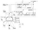
本発明の第1の実施例における治療システムの構成について図1乃至図3を用いて説明する。なお、図1は、本実施例における治療システム全体の概略構成を示すブロック図であり、図2及び図3は、この治療システムの構成要素である診断・治療部のブロック図である。(System configuration)
The configuration of the treatment system according to the first embodiment of the present invention will be described with reference to FIGS. FIG. 1 is a block diagram showing a schematic configuration of the entire treatment system in this embodiment, and FIGS. 2 and 3 are block diagrams of a diagnosis / treatment unit which is a component of the treatment system.
図1において、治療システム100は、治療部位に対して治療用超音波を照射すると共に、この治療部位の実画像データの生成を行なう診断・治療部12と、この診断・治療部12において生成された実画像データの保存や、ネットワーク14を介して画像データサーバ15から供給される3次元の参照画像データの保存を行なう画像データ記憶部5と、画像データ記憶部5に保存された参照画像データに対して画像処理を行なう画像処理部6を備えている。 In FIG. 1, a
更に、治療システム100は、画像データ記憶部5において保存されている所望の実画像データ及び参照画像データや、これらの画像データに対する付帯情報などを表示する表示部8と、治療計画を策定するための焼灼方法や照射条件などの設定や患者情報あるいは各種コマンド信号の入力を行なう入力部9と、ネットワーク14を介して画像データサーバ15から画像データを受信するためのネットワークインターフェース10と、上述の各ユニットを統括的に制御するシステム制御部11を備えている。 Further, the
尚、ネットワーク14を介して治療システム100と接続されている画像データサーバ15は、核医学画像データサーバ15−1、CT画像データサーバ15−2、MRI画像データサーバ15−3、更には超音波画像データサーバ15−4などから構成されている。 The
次に、治療システム100の診断・治療部12は、治療用超音波の照射と実画像データの収集を行なうためにイメージング用超音波の送受波を行なうアプリケータ部1と、治療用超音波を照射するためにアプリケータ部1に対して駆動信号を供給する治療用駆動部2と、イメージング用超音波による実画像データの生成を行なうために前記アプリケータ部1に対して駆動信号を供給すると共に、前記イメージング用超音波の送受波によって得られた受信信号に基づいて実画像データを生成するための信号処理を行なう画像データ生成部4と、前記アプリケータ部1を患者の所定の位置に移動させるための移動機構部3を備えている。 Next, the diagnosis /
図2は、上述のアプリケータ部1、治療用駆動部2、及び移動機構部3の構成を示したブロック図である。 FIG. 2 is a block diagram showing the configuration of the
図2のアプリケータ部1は、例えば、脱気水からなるカップリング液23によって充満されており、その上部には患者51の治療部位(例えば腫瘍)55に対して治療用超音波を照射するための超音波送波器22が装着され、そのほぼ中央部に開口した孔部26には、治療部位55に関する実画像データを生成するために、患者51に対してイメージング用超音波の送受波を行なう超音波プローブ27が回転自在に取り付けられている。そして、超音波プローブ27の先端部、及び超音波送波器22には、電気音響変換素子である圧電振動子が設けられ、この圧電振動子によって治療用超音波の照射やイメージング用超音波の送受波が行なわれる。 The
一方、アプリケータ部1における患者51の体表53との接触部には、高分子材料からなり、前記カップリング液23とほぼ等しい音響インピーダンスを有したカップリング膜24が設けられている。即ち、超音波送波器22から照射される治療用超音波や超音波プローブ27によって送受波されるイメージング用超音波は、患者51とほぼ等しい音響特性を有するカップリング膜24及びカップリング液23を介し、患者51に対して効率良く送受波される。 Meanwhile, a
又、超音波送波器22は、M個の圧電振動子がリング状に配列された、所謂アニュラアレイを形成しており、その前面(凹面)及び後面(凸面)には、駆動信号を供給するための電極及び接地用の電極がそれぞれ装着され、凸面側は支持台に固定されている。一方、凹面側の電極には、患者51に対して治療用超音波の照射を効率良く行なうための音響マッチング層が設けられ、更にその外表面は保護膜によって覆われている。尚、超音波プローブ27については、後述する画像データ生成部4と関連させて説明する。 The
一方、治療用駆動部2は、治療用超音波を照射するために超音波送波器22に対して駆動信号を供給する機能を有し、超音波送波器22を構成する圧電振動子の共振周波数に対応した周波数の連続波を発生するCW発生器36と、この連続波に対して所定の遅延位相を与える位相遅延回路37と、前記連続波を増幅するRFアンプ38と、RFアンプ38の出力信号を超音波送波器22に効率良く供給するためにインピーダンスマッチングを行なうマッチング回路39を備えている。 On the other hand, the
尚、上述の位相遅延回路37、RFアンプ38、及びマッチング回路39は、超音波送波器22における圧電振動子数Mと対応してMチャンネルから構成されている。そして、位相遅延回路37は、超音波送波器22におけるM個の圧電振動子が照射する治療用超音波を所望の距離(焦点距離)に集束させるために、前記圧電振動子に供給されるMチャンネルの駆動信号に対して所定の遅延位相を設定する。尚、位相遅延回路37において設定される各チャンネルの位相遅延量は、アニュラアレイ圧電振動子の半径や焦点距離によって一義的に決定される。 The
一方、移動機構部3は、治療用超音波の焦点52、あるいは実画像断面が治療部位55に合致するように、前記アプリケータ部1の移動や超音波プローブ27の回転を行なう移動機構31と、システム制御部11からの指示信号に従ってアプリケータ部1の移動方向や移動距離、あるいは超音波プローブ27の回転角度などを設定するための制御信号を移動機構31に供給する機構制御回路32と、移動機構31によるアプリケータ部1の移動方向や移動量あるいは回転角度などの位置情報を検出する位置検出器33を備えている。そして、位置検出器33によって検出された位置情報は、機構制御回路32を介してシステム制御部11に供給される。 On the other hand, the
次に、診断・治療部12の画像データ生成部4と超音波プローブ27につき図3を用いて説明する。画像データ生成部4は、アプリケータ部1の超音波プローブ27に接続され、超音波プローブ27に対して駆動信号を供給すると共に、超音波プローブ27から得られる受信信号に基づいて治療部位55における実画像データを生成する。即ち、画像データ生成部4と超音波プローブ27によって治療部位55における治療用超音波の照射状況や治療効果のリアルタイム観察が行なわれる。 Next, the image
超音波プローブ27は、通常の超音波診断装置において使用されるものと同様な超音波プローブを用いることが可能であるが、特にアプリケータ部1の超音波送波器22による治療用超音波の照射の妨げにならないように、小さな超音波送受信面で広い範囲の画像化が可能なセクタ走査用の超音波プローブが好適である。 As the
そして、超音波プローブ27の先端部は、例えば1次元にN個配列された図示しない圧電振動子を有し、この圧電振動子によって、送信時には電気パルス(駆動信号)を超音波パルス(送信超音波)に変換して患者51に送信し、また受信時には患者51からの超音波反射波(受信超音波)を電気信号(受信信号)に変換する。 The distal end portion of the
一方、図3の画像データ生成部4は、超音波プローブ27から患者51に対して送信超音波を放射するための駆動信号を生成するイメージング用駆動部61と、患者51からの受信超音波を超音波プローブ27を介して受信するイメージング用受信部62と、この受信信号に基づいて超音波画像データを生成するための信号処理を行なう受信信号処理部63を備えている。 On the other hand, the image
そして、イメージング用駆動部61は、レートパルス発生器66と、送信遅延回路67と、パルサ68を備えており、レートパルス発生器66は、患者51に放射する送信超音波の繰り返し周期を決定するレートパルスを発生して送信遅延回路67に供給する。又、送信遅延回路67は、送信超音波を所定の深さに集束するための遅延時間と所定の方向に放射して患者51を走査するための遅延時間をレートパルスに与え、このレートパルスをパルサ68に供給する。そして、パルサ68は、レートパルスに同期した駆動信号を生成し、この駆動信号を超音波プローブ27の圧電振動子に供給する。 The imaging drive unit 61 includes a
一方、イメージング用受信部62は、前記圧電振動子によって電気信号に変換された受信信号を増幅し十分なS/Nを確保するプリアンプ69と、受信遅延回路70と、加算器71とを備えている。受信遅延回路70は、細い受信ビーム幅を得るために所定の深さからの受信超音波を集束するための遅延時間と、受信超音波の指向性を制御し患者51を走査するための遅延時間とをプリアンプ69の出力に与えた後、加算器71に送り、加算器71は、複数チャンネルの受信信号を加算して1チャンネルに纏める。 On the other hand, the imaging reception unit 62 includes a
尚、上述の送信遅延回路67、パルサ68、プリアンプ69、及び受信遅延回路70は、通常、超音波プローブ27におけるN個の圧電振動子に対応したNチャンネルの回路から構成されている。 Note that the
次に、受信信号処理部63は、対数変換器72と、包絡線検波器73と、A/D変換器74とを備えている。受信信号処理部63の入力信号は、対数変換器72においてその信号振幅が対数変換され、弱い信号が相対的に強調される。又、包絡線検波器73は、対数変換された受信信号に対して包絡線検波を行ない、A/D変換器74は、この包絡線検波信号をA/D変換して実画像データを生成する。 Next, the received signal processing unit 63 includes a
図1に戻って、画像データ記憶部5は、患者51に対する治療行為の際に画像データ生成部4から供給される実画像データを保存する実画像データ記憶領域と、ネットワーク14を介して画像データサーバ15のCT画像データサーバ15−2から供給される前記患者51の参照画像データ、あるいは、この参照画像データに対して画像処理部6が行なう画像処理によって得られた処理後の参照画像データを保存する参照画像データ記憶領域を備えている。そして、これらの画像データ記憶領域において、2次元あるいは3次元の実画像データ及び参照画像データが保存される。 Returning to FIG. 1, the image
又、画像処理部6は、図示しない演算回路と記憶回路を備え、画像データ記憶部5の参照画像データ記憶領域に保存された3次元の参照画像データに対して、例えば、ボリュームレンダリング法を用いた画像処理を行ない、臓器や血管あるいは腫瘍などの境界面あるいは表面が強調表示された参照画像データ(以下、ボリュームレンダリング画像データと呼ぶ。)を生成する。又、入力部9から入力された仮想アプリケータの位置情報に基づいて前記3次元の参照画像データの中から所望の2次元の参照画像データ(以下、MPR(multi planar reconstruction)画像データと呼ぶ。)の抽出を行なう。 The image processing unit 6 includes an arithmetic circuit and a storage circuit (not shown). For example, a volume rendering method is used for the three-dimensional reference image data stored in the reference image data storage area of the image
一方、表示部8は、図示しない表示用データメモリと、変換回路と、モニタを備えており、ネットワーク14を介して画像データサーバ15から供給された参照画像データや画像処理部6において画像処理されて得られた処理後の参照画像データ、更には、画像データ生成部4によって生成された実画像データを独立あるいは並列して表示する。又、これらの実画像データや参照画像データに対して、治療用超音波のビーム幅や焦点位置、後述する仮想アプリケータの位置情報に対応した前記MPR画像の断面位置、更には、入力部9から入力される患者情報等の各種入力データなどが付帯情報として重畳表示される。 On the other hand, the
即ち、上述の各画像データと付帯情報は、表示用データメモリで所定フォーマットに従って合成され、変換回路においてD/A変換とテレビフォーマット変換が行われた後CRTあるいは液晶などのモニタに表示される。 That is, the above-described image data and incidental information are combined according to a predetermined format in the display data memory, and after being subjected to D / A conversion and television format conversion in the conversion circuit, are displayed on a monitor such as a CRT or a liquid crystal display.
次いで、入力部9は、操作パネル上に液晶パネル、キーボード、トラックボール、マウス、選択ボタン等の入力デバイスを備え、患者情報の入力、治療対象臓器やアプリケータ部1の選択、照射条件や焼灼方法の設定、参照画像データ及び画像処理方法の選択、参照画像データに対する仮想アプリケータの位置及び方向の設定、更には、種々のコマンド信号の入力などを行なうことが可能である。特に、参照画像上に重畳表示される仮想アプリケータの位置や方向を前記入力デバイスを用いて変更することによって、所望の断面におけるMPR画像データを生成することができる。 Next, the input unit 9 includes input devices such as a liquid crystal panel, a keyboard, a trackball, a mouse, and a selection button on the operation panel, and inputs patient information, selection of a treatment target organ and
そして、システム制御部11は、図示しないCPU(中央演算処理装置)と記憶回路を備え、入力部9からのコマンド信号に従って各ユニットの制御やシステム全体の制御を統括して行なう。又、システム制御部11の記憶回路19には、入力部9を介して供給される入力情報、設定情報、選択情報、更には種々のコマンド信号などが一旦保存される。 The system control unit 11 includes a CPU (Central Processing Unit) and a storage circuit (not shown), and controls each unit and the entire system according to a command signal from the input unit 9. The storage circuit 19 of the system control unit 11 temporarily stores input information, setting information, selection information, and various command signals supplied via the input unit 9.
(治療の手順)
次に、本実施例における治療手順を、図1乃至図6を用いて説明する。図4は、本実施例の治療システム100による治療手順を示すフローチャートである。(Treatment procedure)
Next, the treatment procedure in the present embodiment will be described with reference to FIGS. FIG. 4 is a flowchart showing a treatment procedure by the
治療に先立って、治療対象患者51の担当医(以下、操作者と呼ぶ)や他の医師、あるいは検査技師は、患者51に対してヘリカルスキャン方式あるいはマルチスライス方式などのCT装置を用いて3次元の参照画像データを収集し、ネットワーク14を介して治療システム100と接続されている画像データサーバ15のCT画像データサーバ15−2に保存する。尚、CT装置による画像データの生成方法は、通常の臨床の場で行なわれている方法と同様であるため、詳細な説明は省略する。 Prior to treatment, a doctor in charge of the patient to be treated 51 (hereinafter referred to as an operator), another doctor, or a laboratory technician uses a CT apparatus such as a helical scan method or a multi-slice method for the
次いで、操作者は、図1に示した治療システム100の入力部9において患者情報を入力した後、参照画像データとして「CT画像データ」、参照画像データに対する画像処理法として「ボリュームレンダリング」、治療対象臓器として「肝臓」を選択する。 Next, the operator inputs patient information at the input unit 9 of the
入力部9よりこれらの選択信号が供給されたシステム制御部11は、ネットワークインターフェース10,及びネットワーク14を介して画像データサーバ5のCT画像データサーバ15−2を選択し、このCT画像データサーバ15−2に保存されている当該患者51の「肝臓」に対して予め収集された3次元の参照画像データを読み出す。 The system control unit 11 to which these selection signals are supplied from the input unit 9 selects the CT image data server 15-2 of the
そして、読み出した参照画像データを、ネットワーク14及びネットワークインターフェース10を介して治療システム100の画像データ記憶部5における参照画像データ記憶領域に保存する(図4のステップS1)。 Then, the read reference image data is stored in the reference image data storage area in the image
参照画像データの画像データ記憶部5への保存が終了したならば、システム制御部11は、「ボリュームレンダリング」による画像処理を行なうための制御信号を画像処理部6に供給し、画像処理部6は、画像データ記憶部5に保存されている3次元の参照画像データを読み出し、記憶回路に一旦保存する。次いで、画像処理部6の演算回路は、記憶回路に予め保存されている「ボリュームレンダリング」処理プログラムを用い、前記参照画像データに対して画像処理を施すことによって生成したボリュームレンダリング画像データを表示部8に表示する(図4のステップS2)。 When the storage of the reference image data in the image
一方、操作者は、入力部9において入力された患者情報や選択された治療対象臓器、更には、ボリュームレンダリング画像において観察される治療部位55までの距離に基づいて最適な仕様、即ち圧電振動子の外径、曲率半径、圧電振動子数(M)、圧電振動子の共振周波数などを有したアプリケータ部1を選択する(図4のステップS3)。 On the other hand, the operator selects the optimum specification based on the patient information input at the input unit 9, the selected treatment target organ, and the distance to the
次いで、操作者は、表示部8に表示されたボリュームレンダリング画像を必要に応じて所望の角度だけ回転させた後、この画像上の体表位置に仮想アプリケータを配置する。尚、上記のボリュームレンダリング画像の回転や、仮想アプリケータの設定、あるいは仮想アプリケータの位置や方向などの変更は、入力部9の入力デバイスを用いて行なわれる。 Next, the operator rotates the volume rendering image displayed on the
図5は、仮想アプリケータによるMPR画像断面の設定方法を示す図であり、図5(a)は、ボリュームレンダリング画像の体表位置に配置された仮想アプリケータ81と、この仮想アプリケータ81の位置情報によって自動設定されるMPR画像の仮想画像断面82を示している。この仮想アプリケータ81は、図5(b)に示すように仮想超音波送波器83と仮想超音波プローブ84から構成され、仮想超音波プローブ84は、仮想アプリケータ81の中央部を中心に回転可能となっている。そして、上述の仮想画像断面82は、仮想超音波プローブ84のマーカ85で示された圧電振動子の配列方向、即ちイメージング用超音波の走査方向に対応している。 FIG. 5 is a diagram illustrating a method for setting an MPR image cross section by a virtual applicator. FIG. 5A illustrates a
システム制御部11は、表示部8に表示されたボリュームレンダリング画像において設定された仮想アプリケータ81の位置情報を入力部9から読み出して画像処理部6に供給する。そして、画像処理部6は、供給された位置情報に基づいて一義的に決定される仮想画像断面82を前記ボリュームレンダリング画像データに重畳して表示部8に表示する。 The system control unit 11 reads the position information of the
次いで、操作者は、仮想アプリケータ81の位置や角度の変更に伴って更新される前記仮想画像断面82を観測し、この仮想画像断面82が、ボリュームレンダリング画像上に表示されている治療部位90に対して最適な位置になる場合の仮想アプリケータ81の位置を設定する(図4のステップS4)。そして、このとき入力部9から送られる仮想アプリケータ81の位置情報は、システム制御部11の記憶回路に保存される。 Next, the operator observes the
一方、画像処理部6は、設定された仮想アプリケータ81の位置情報に基づいて前記仮想画像断面82に対応する画像のアドレスデータを算出する。次いで、このアドレスデータに基づいて、画像データ記憶部5に保存されている3次元の参照画像データの中から所望の2次元の参照画像データを抽出し、MPR画像データを生成する。そして、生成されたMPR画像データは、表示部8に表示される。(図4のステップS5)。 On the other hand, the image processing unit 6 calculates address data of an image corresponding to the
尚、このMPR画像データには、選択したアプリケータ部1の仕様によって決定される治療用超音波のビーム幅や焦点位置の情報が重畳され、表示部8に表示されたMPR画像において、治療用超音波の照射が肋骨(図5の肋骨70)や図示しない肺などの臓器の影響をあまり受けないこと、あるいは、治療用超音波の焦点52が治療部位55の領域に設定されていることなどの確認が行なわれる。 The MPR image data is superimposed with the information on the beam width and focal position of the therapeutic ultrasound determined by the specifications of the selected
次に、操作者は、表示部8に表示されたMPR画像上の治療部位90に対し、治療用超音波による焼灼範囲、焼灼間隔、焼灼順序などの焼灼方法、更には、照射エネルギーや照射時間などの照射条件を設定する(図4のステップS6)。尚、この照射条件は、上述のMPR画像において観察される肋骨70や肺の治療用超音波に対する遮蔽度、あるいは治療部位55の深度などを考慮して経験的に決定される。 Next, the operator applies an ablation method such as an ablation range, an ablation interval, an ablation order, etc., as well as an irradiation energy and an irradiation time for the
以上述べた手順により治療計画、(即ち、上述のアプリケータ部1の選択、アプリケータ部1の位置、焼灼方法、照射条件などの設定)の策定が終了したならば、操作者は、図4のステップS3において選択したアプリケータ部1を診断・治療部12の図示しないアプリケータ支持部に装着し、治療計画において設定された仮想アプリケータ81の位置情報、あるいはMPR画像情報に基づいて前記アプリケータ部1の中心位置、方向、及び傾斜角度を設定する(図4のステップS7)。 When the treatment plan (ie, selection of the
次いで、診断・治療部12の画像データ生成部4は、操作者によって入力部9より入力される画像データ生成コマンドに従がい、アプリケータ部1の超音波プローブ27を用いて実画像データの生成を行なう。 Next, the image
患者51へのイメージング用超音波の送信に際して、図3に示したイメージング用駆動部61のレートパルス発生器66は、システム制御部11からの制御信号に従い、患者51に放射する送信超音波の繰り返し周期を決定するレートパルスをNチャンネルの送信遅延回路67に供給する。 When transmitting the imaging ultrasound to the
送信遅延回路67は、イメージング用の送信超音波を所定の深さに集束するための遅延時間と、所定の方向に超音波を送信するための遅延時間をレートパルスに与え、このレートパルスをNチャンネルのパルサ68に供給する。そして、パルサ68は、前記レートパルスに同期した駆動信号を生成し、超音波プローブ27のN個の圧電振動子に供給して患者51の第1の方向(θ1方向)に送信超音波を放射する。 The
患者51に放射された送信超音波の一部は、音響インピーダンスの異なる患者51の臓器境界面あるいは組織内にて反射し、超音波プローブ27のN個の圧電振動子によって受信されて電気信号に変換される。次いで、変換された受信信号は、Nチャンネルのプリアンプ69にて増幅され、更に、Nチャンネルの受信遅延回路70に供給される。 A part of the transmission ultrasonic wave radiated to the
受信遅延回路70は、所定の深さからの超音波を集束して受信するための遅延時間と、θ1方向に強い受信指向性をもたせて受信するための遅延時間を受信信号に与えた後、この受信信号を加算器71へ送る。そして、加算器71はプリアンプ69、受信遅延回路70を介して入力されるNチャンネルの受信信号を加算合成し、1つの受信信号に纏めて受信信号処理部63へ供給する。 The
次いで、加算器71の出力は、受信信号処理部63の対数変換器72、包絡線検波器73、A/D変換器74において、対数変換、包絡線検波、A/D変換がなされて実画像データが生成され、この実画像データは、図1の画像データ記憶部5における実画像データ記憶領域に保存される。 Next, the output of the adder 71 is subjected to logarithmic conversion, envelope detection, and A / D conversion in a
引き続いて、システム制御部11は、超音波の送受信方向をΔθずつ更新させながらθ1方向の場合と同様な手順で第2の走査方向(θ2)乃至第Lの走査方向(θL)に超音波の送受波を行なう。即ち、システム制御部11は、送信遅延回路67及び受信遅延回路70の遅延時間を超音波送受波方向に対応させて順次更新して2次元走査し、実画像データのための受信信号の収集を行なう。そして、得られた受信信号に基づいて生成された実画像データを画像データ記憶部5に保存し、所定範囲(θ1乃至θL)の走査が終了した時点で保存された実画像データを表示部8においてリアルタイム表示する。このとき、表示部8では、治療計画設定において得られたMPR画像と前記実画像は並列表示される(図4のステップS8)。 Subsequently, the system control unit 11 updates the transmission / reception direction of the ultrasonic wave by Δθ in the same procedure as in the θ1 direction, and performs ultrasonic wave transmission in the second scanning direction (θ2) to the Lth scanning direction (θL). Transmit and receive waves. That is, the system control unit 11 sequentially updates the delay times of the
操作者は、MPR画像と並べてリアルタイム表示される実画像を観察し、両者の断面位置に許容できない差異がある場合には、実画像のリアルタイム表示を継続した状態で、入力部9に設けられた入力デバイスを用いてアプリケータ部1の位置を再設定する。このとき、入力部9から出力された位置信号はシステム制御部11に供給され、システム制御部11は、この位置信号に基づいて位置制御信号を移動機構部3に供給してアプリケータ部1を所定の方向に移動する。 The operator observes the real image displayed in real time side by side with the MPR image, and if there is an unacceptable difference between the cross-sectional positions of the two, the operator is provided with the input unit 9 in a state in which the real image is continuously displayed. The position of the
リアルタイム表示される実画像データが、MPR画像データと同じ画像断面位置になるまで操作者は上述の手順を繰り返し、アプリケータ部1の中心位置、回転角度、更には傾斜角度の更新を行なう。 The operator repeats the above-described procedure until the real image data displayed in real time reaches the same image cross-sectional position as the MPR image data, and updates the center position, rotation angle, and tilt angle of the
尚、アプリケータ部1の超音波プローブ27と超音波送波器22は、一体化して取り付けられているため、これらの相対位置も一義的に決定される。即ち、超音波送波器22における圧電振動子の曲率半径と、この圧電振動子に供給される駆動信号の位相遅延量によって決定される治療用超音波のビーム幅や焦点の位置はMPR画像のみならず実画像においても重畳表示される。 Since the
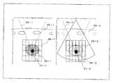
次に、最適位置の設定が終了したアプリケータ部1を用いて得られた実画像データにおいて、既に治療計画において設定された焼灼範囲、焼灼間隔あるいは焼灼順序が治療用超音波のビーム幅や焦点と同時に重畳表示される。図6は、表示部8のモニタに並列表示されるMPR画像85−1と実画像85−2を示したものであり、夫々の画像には治療用超音波のビーム幅86−1及び86−2、焦点マーカ87−1及び87−2、焼灼範囲と照射間隔88−1及び88−2が治療部位の画像90−1及び90−2が重畳表示されている。 Next, in the real image data obtained using the
そして、操作者は、実画像85−2において、治療用超音波のビームの肋骨による遮蔽量が許容できること、焦点マーカ87が治療部位の画像90−2のほぼ中心に位置していること、更には、焼灼範囲88の大きさが治療部位の画像90−2に対して適当であることなどを確認し、特に、焼灼範囲88が適当でない場合には入力部9より再設定を行なう(図4のステップS9)。 Then, the operator can tolerate the amount of shielding of the therapeutic ultrasound beam by the ribs in the actual image 85-2, that the focus marker 87 is positioned substantially at the center of the treatment site image 90-2, and Confirms that the size of the ablation range 88 is appropriate for the image 90-2 of the treatment site. In particular, when the ablation range 88 is not appropriate, resetting is performed from the input unit 9 (FIG. 4). Step S9).
上述の手順によって所望の画像断面におけるアプリケータ部1の位置や焼灼範囲等の確認あるいは再設定が終了したならば、アプリケータ部1を実画像データの画像断面に対して垂直な方向(図5のY軸方向:以下、スライス方向と呼ぶ。)に移動させて同様な確認を行ない、必要に応じて変更を行なう。(図4のステップS10)。 When the confirmation or resetting of the position, cauterization range, etc. of the
次に、操作者は、入力部9より治療用超音波の照射開始コマンドを入力する。 Next, the operator inputs a therapeutic ultrasound irradiation start command from the input unit 9.
図2において、入力部9から入力された照射開始コマンド信号を受信したシステム制御部11は、治療計画において設定された最初の照射位置に治療用超音波の焦点52が形成されるように、移動機構部3の移動機構31、及び治療用駆動部2の位相遅延回路37に制御信号を供給する。 In FIG. 2, the system control unit 11 that has received the irradiation start command signal input from the input unit 9 moves so that the
そして、移動機構31は、アプリケータ部1を患者51の体表53に沿って所定の位置に移動する。一方、システム制御部11は、治療用超音波の集束距離と前記最初の照射位置の深さが一致するための位相遅延データを、システム制御部11の記憶回路に設けられた図示しないルックアップテーブルから読み出し、この位相遅延データを位相遅延回路37に供給する。 Then, the moving
最初の照射位置に対するアプリケータ部1の位置の設定と位相遅延量の設定が終了したならば、システム制御部11は、治療用駆動部2のCW発生器36に対して所定周波数の連続波を発生させる。この連続波は、Mチャンネルから構成される位相遅延回路37において上述の位相遅延量が与えられた後、RFアンプ38及びマッチング回路39を経て、アプリケータ部1の超音波送波器22を構成するM個のアニュラアレイ圧電振動子に供給される。 When the setting of the position of the
この連続波の駆動によって超音波送波器22から照射された治療用超音波は、治療計画にて設定された最初の照射位置に集束し、この照射位置にある治療部位55を焼灼する。 The therapeutic ultrasonic wave emitted from the
一方、超音波送波器22によって治療用超音波が照射された最初の照射位置の焼灼状態は、アプリケータ部1の超音波プローブ27と図1に示した診断・治療部12の画像データ生成部4によって生成されて表示部8にリアルタイム表示される実画像によってモニタリングされる。 On the other hand, the cauterization state of the first irradiation position irradiated with therapeutic ultrasonic waves by the
最初の照射位置への治療用超音波の照射と、この照射位置における実画像の観察が行われた後、照射計画に従って第2の照射位置、更には第3以降の照射位置に対しても同様の手順によって治療用超音波の照射と、実画像による焼灼状態のモニタリングが行なわれる。更に、移動機構部3を制御してアプリケータ部1をスライス方向に移動させることにより、3次元的に拡がった治療部位55の任意の位置に対する治療用超音波の照射と実画像によるモニタリングを行なう。(図4のステップS11)。 After the treatment ultrasonic wave is irradiated to the first irradiation position and the actual image is observed at this irradiation position, the same applies to the second irradiation position and further to the third and subsequent irradiation positions according to the irradiation plan. In this procedure, irradiation with therapeutic ultrasonic waves and monitoring of the ablation state using actual images are performed. Further, by controlling the moving
治療計画において予め設定された全ての照射位置に対する治療用超音波の照射が終了したならば、操作者は、3次元の実画像データを収集するためのコマンドを入力部9より入力する。そして、このコマンド信号を受信したシステム制御部11は、画像データ生成部4の各ユニットに対して実画像データの収集を継続する指示信号を供給し、更に、移動機構部3に対してアプリケータ部1をスライス方向に移動するための制御信号を供給する。 When irradiation of therapeutic ultrasonic waves to all irradiation positions set in advance in the treatment plan is completed, the operator inputs a command for collecting three-dimensional actual image data from the input unit 9. Upon receiving this command signal, the system control unit 11 supplies an instruction signal for continuing the collection of the actual image data to each unit of the image
これらの指示信号と制御信号を受信した画像データ生成部4及び移動機構部3は、アプリケータ部1をスライス方向に移動させながら実画像データの生成を行ない、得られた3次元的な実画像データは画像データ記憶部5の実画像データ記憶領域に保存される(図4のステップS12)。 The image
次に、システム制御部11は、入力部9から入力されるコマンド信号に従って、画像データ記憶部5に保存された3次元参照画像データ及び3次元実画像データの中から同一画像断面における2次元参照画像データと2次元実画像データを順次読み出し、表示部8のモニタにおいて、比較表示する(図4のステップS13)。 Next, the system control unit 11 performs two-dimensional reference in the same image section from the three-dimensional reference image data and the three-dimensional actual image data stored in the image
そして、操作者は、並べて表示された治療前の画像データ(参照画像データ)と治療後の画像データ(実画像データ)を比較し(図4のステップS14)、目標とした治療効果、あるいは顕著な治療効果が認められた場合には治療を終了する(図4のステップS15)。一方、更なる治療が要求される場合、治療計画の再設定が必要ならば図4のステップS3に戻り、又、照射強度が不足している場合には図4のステップS11にもどって治療を継続する。 Then, the operator compares the pre-treatment image data (reference image data) and the post-treatment image data (actual image data) displayed side by side (step S14 in FIG. 4), and the target treatment effect or remarkable If a significant therapeutic effect is recognized, the treatment is terminated (step S15 in FIG. 4). On the other hand, if further treatment is required, if it is necessary to reset the treatment plan, the process returns to step S3 in FIG. 4. If the irradiation intensity is insufficient, the process returns to step S11 in FIG. continue.
以上述べた本実施例によれば、治療部位に対し治療用超音波を用いた焼灼を行なう際、同じ患者から治療前に得られた3次元画像データに基づいた詳細な治療計画が策定できる。従って、精度の良い治療が可能となり、治療途中における治療計画の変更や治療の繰り返しを低減できるため、治療効率が向上すると共に正確かつ安全な治療が可能となる。更に、治療前後の3次元画像情報の比較観察によって治療効果を容易に把握することができ、治療効果が不充分な場合には治療計画の再策定と、この治療計画に基づいた治療を引き続き行なうことが可能となる。 According to the present embodiment described above, a detailed treatment plan based on the three-dimensional image data obtained from the same patient before the treatment can be formulated when performing ablation using the therapeutic ultrasound on the treatment site. Therefore, treatment with high accuracy is possible, and changes in treatment plan and treatment repetition during treatment can be reduced, so that treatment efficiency is improved and accurate and safe treatment is possible. Furthermore, the treatment effect can be easily grasped by comparative observation of the three-dimensional image information before and after the treatment. When the treatment effect is insufficient, the treatment plan is re-developed and the treatment based on the treatment plan is continued. It becomes possible.
又、異なる画像診断装置によって得られる実画像データと参照画像データを用いることによって、互いの欠点を補完することができる。例えば、超音波画像では低コントラストゆえに診断が困難な治療部位がCT画像では鮮明に表示できる場合がある。 Moreover, the mutual fault can be complemented by using the real image data and reference image data obtained by different image diagnostic apparatuses. For example, there are cases where a treatment site that is difficult to diagnose due to low contrast in an ultrasound image can be clearly displayed in a CT image.
次に、本発明の第2の実施例における治療支援システムにつき図7及び図8を用いて説明する。この治療支援システムは、患者に対し治療前に予め収集した参照画像データに基づいて治療部位に対する治療計画を策定し、この治療計画データと参照画像データを診断・治療装置に供給することを特徴としている。尚、この実施例においても、上述の第1の実施例と同様にして、治療前の患者に対して3次元のCT画像データを参照画像データとして収集し、この参照画像データに基づいて強力超音波による治療のための治療計画を策定する場合を例に説明する。 Next, a treatment support system according to a second embodiment of the present invention will be described with reference to FIGS. This treatment support system is characterized in that a treatment plan for a treatment site is formulated based on reference image data collected in advance before treatment for a patient, and the treatment plan data and reference image data are supplied to a diagnosis / treatment device. Yes. In this embodiment as well, as in the first embodiment described above, three-dimensional CT image data is collected as reference image data for a patient before treatment, and based on this reference image data, A case where a treatment plan for treatment with sound waves is formulated will be described as an example.
(システムの構成)
本発明の第2の実施例における治療支援システムの構成につき図7のブロック図を用いて説明する。図7の治療支援システム200は、ネットワーク14を介して画像データサーバ15から供給される3次元の参照画像データの保存を行なう画像データ記憶部105と、画像データ記憶部105に保存された参照画像データに対して画像処理を行なう画像処理部106を備えている。更に、治療支援システム200は、画像データ記憶部105において保存されている所望の参照画像データや、参照画像データに対する付帯情報などを表示する表示部108と、治療計画を策定するための焼灼方法や照射条件などの設定や患者情報、あるいは各種コマンドの入力を行なう入力部109と、ネットワーク14を介して画像データサーバ15から参照画像データを受信するためのネットワークインターフェース110と、上述の各ユニットを統括的に制御するシステム制御部111を備えている。(System configuration)
The configuration of the treatment support system according to the second embodiment of the present invention will be described with reference to the block diagram of FIG. The treatment support system 200 of FIG. 7 includes an image data storage unit 105 that stores three-dimensional reference image data supplied from the
尚、ネットワーク14を介して治療支援システム200と接続されている画像データサーバ15は、核医学画像データサーバ15−1、CT画像データサーバ15−2、MRI画像データサーバ15−3、更には超音波画像データサーバ15−4などから構成されている。一方、治療支援システム200の画像データ記憶部105に一旦保存された2次元あるいは3次元の参照画像データは、診断・治療装置150からの画像データ要求コマンド信号に従って、診断・治療装置150に供給され、診断・治療装置150において生成される実画像データと比較表示される。 The
(治療支援の手順)
次に、本実施例における治療支援手順を図7のブロック図と図8のフローチャートを用いて説明する。(Treatment support procedure)
Next, the treatment support procedure in the present embodiment will be described with reference to the block diagram of FIG. 7 and the flowchart of FIG.
治療に先立って、治療支援システム200の操作者は、患者51に対してCT装置を用いて3次元の参照画像データを収集し、ネットワーク14を介して治療支援システム200と接続されている画像データサーバ15のCT画像データサーバ15−2に保存する。 Prior to the treatment, the operator of the treatment support system 200 collects three-dimensional reference image data from the patient 51 using a CT apparatus, and is connected to the treatment support system 200 via the network 14. The data is stored in the CT image data server 15-2 of the
次いで、操作者は、図1に示した治療支援システム200の入力部109において患者情報を入力した後、参照画像データとして「CT画像データ」、前記参照画像データに対する画像処理法として「ボリュームレンダリング」、治療対象臓器として「肝臓」を夫々選択する。 Next, the operator inputs patient information at the
これらの選択信号が供給されたシステム制御部111は、ネットワークインターフェース110及びネットワーク14を介して画像データサーバ15のCT画像データサーバ15−2を選択し、このCT画像データサーバ15−2に保存されている当該患者51の「肝臓」に関する3次元の参照画像データを読み出す。 The
そして、読み出した参照画像データを、ネットワーク14及びネットワークインターフェース110を介して治療支援システム200の画像データ記憶部105に保存する(図8のステップS21)。 Then, the read reference image data is stored in the image data storage unit 105 of the treatment support system 200 via the network 14 and the network interface 110 (step S21 in FIG. 8).
次に、システム制御部111は、「ボリュームレンダリング」による画像処理を行なうための制御信号を画像処理部106に供給し、画像処理部106は、画像データ記憶部105に保存されている3次元の参照画像データを読み出す。そして、前記参照画像データに対してボリュームレンダリング処理を施すことによって臓器や血管、更には腫瘍などの表面抽出を行ない、得られたボリュームレンダリング画像データを表示部108に表示する(図8のステップS22)。 Next, the
一方、操作者は、入力部109において入力された患者情報や選択された治療対象臓器、更には、ボリュームレンダリング画像において観察される治療部位55までの距離に基づいて治療アプリケータの選択を行なう(図8のステップS23)。そして、表示部108に表示されたボリュームレンダリング画像上の体表位置に仮想アプリケータを配置する。 On the other hand, the operator selects the treatment applicator based on the patient information input at the
一方、システム制御部111は、表示部108に表示されたボリュームレンダリング画像上に配置された仮想アプリケータの位置情報を入力部109から読み出し、この位置情報を画像処理部106に供給する。そして、画像処理部106は、供給された位置情報に基づいて一義的に決定される仮想画像断面データを前記ボリュームレンダリング画像データに追加し、更に、このボリュームレンダリング画像データと仮想画像断面データを重畳して表示部108に表示する。 On the other hand, the
次いで、操作者は、仮想画像断面82がボリュームレンダリング画像上の治療部位55に対して最適な位置になるように仮想アプリケータの位置を設定する(図8のステップS24)。 Next, the operator sets the position of the virtual applicator so that the
一方、画像処理部106は、設定された仮想アプリケータの位置情報をシステム制御部111を介して読み出し、この位置情報に基づいて仮想画像断面82に対応する画像のアドレスデータを算出し、更に、このアドレスデータに基づいて、画像データ記憶部105に保存されている3次元の参照画像データの中から所望の2次元の参照画像データ(MPR画像データ)を読み出す。そして、読み出されたMPR画像データは、表示部108に表示される。(図8のステップS25)。尚、このMPR画像には、選択した治療アプリケータの仕様によって決定される治療用超音波のビーム幅や焦点の位置が重畳表示される。 On the other hand, the
次に、操作者は、表示部108のMPR画像に表示されている治療部位55に対し、治療用超音波の焼灼方法や照射条件などを設定する。(図8のステップS26)。そして、得られた治療計画データと2次元あるいは3次元の参照画像データは診断・治療装置150に供給される。(図8のステップS27)。 Next, the operator sets a therapeutic ultrasound cauterization method, irradiation conditions, and the like for the
以上述べた本実施例によれば、治療部位に対し治療用超音波を用いた焼灼を行なう際、同じ患者から治療前に得られた3次元画像データに基づいた詳細な治療計画を策定することができ、この治療計画データを受けた診断・治療装置は、治療途中における治療計画の変更や治療の繰り返しを低減できるため、治療効率が向上すると共に正確かつ安全な治療が可能となる。 According to the present embodiment described above, when ablation using therapeutic ultrasound is performed on a treatment site, a detailed treatment plan based on the three-dimensional image data obtained from the same patient before the treatment is formulated. The diagnosis / treatment device that has received the treatment plan data can reduce the change of the treatment plan during the treatment and the repetition of the treatment, thereby improving the treatment efficiency and enabling accurate and safe treatment.
尚、本発明は、上述した実施例に限定されるものではなく、種々変形して実施することが可能である。例えば、上述の実施例において述べたように、異なる画像診断装置によって得られた実画像データと参照画像データを用いることによって互いの欠点を補完することができるが、同一の画像診断装置を用いてもよい。この場合、得られた実画像データと参照画像データの比較が容易となり、重畳表示あるいはサブトラクション表示を行なうことも可能となる。又、実画像データと参照画像データの生成は、同一の診断・治療部12、あるいは診断・治療装置150によって行なうことができるため、ネットワーク14を介して参照画像データを収集する必要が無くなる。更に、治療効果が不充分ゆえに治療を繰り返す場合には、実画像データを新たな参照画像データとして用いてもよい。 In addition, this invention is not limited to the Example mentioned above, It can be implemented in various deformation | transformation. For example, as described in the above-described embodiments, the mutual defect can be complemented by using the real image data and the reference image data obtained by different image diagnostic apparatuses, but the same image diagnostic apparatus is used. Also good. In this case, it is easy to compare the obtained actual image data and reference image data, and it is possible to perform superimposed display or subtraction display. Further, since the actual image data and the reference image data can be generated by the same diagnosis /
一方、上述の実施例におけるアプリケータ部1の超音波プローブ27、あるいは超音波送波器22は、2次元配列された圧電振動子を用いてもよく、この場合、治療用超音波の焦点位置や実画像断面の設定は全て電子的に制御することができるため移動機構部3を省くことも可能となる。 On the other hand, the
又、参照画像データに対する画像処理は、「ボリュームレンダリング」に限定されるものではなく、例えば「サーフィスレンダリング」など、他の画像処理方法であってもよい。 Further, the image processing for the reference image data is not limited to “volume rendering”, but may be another image processing method such as “surface rendering”.
更に、画像データサーバ15から供給される参照画像データは、PET画像データのように代謝画像データであってもよい。 Further, the reference image data supplied from the
一方、診断・治療部12、あるいは診断・治療装置150における実画像データ生成手段及び治療手段は、超音波診断装置及び強力超音波治療装置に限定されるものではなく、他の診断装置や治療装置であってもよい。例えば、アプリケータ部1は、MCT,RFA,PEIもしくは穿刺生検用の穿刺針、治療用カテーテルであってもよく、又、内視鏡や腹腔鏡、更には胸腔鏡であってもよい。 On the other hand, the actual image data generation means and the treatment means in the diagnosis /
又、上記実施例では、ネットワーク14を介して画像データサーバ15から供給された参照画像データを画像データ記憶部5あるいは画像データ記憶部105に一旦保存する場合について述べたが、画像処理部6あるいは画像処理部106は、画像データサーバ15から直接供給される参照画像データに対して所望の画像処理を行なってもよい。 In the above embodiment, the case where the reference image data supplied from the
更に、上述の実施例における患者情報は、入力部9あるいは入力部109において操作者によって直接入力されたが、ネットワーク14を介して接続された病院情報システム(HIS)などから供給されてもよい。 Furthermore, the patient information in the above-described embodiment is directly input by the operator at the input unit 9 or the
1…アプリケータ部
2…治療用駆動部
3…移動機構部
4…画像データ生成部
5…画像データ記憶部
6…画像処理部
8…表示部
9…入力部
10…ネットワークインターフェース
11…システム制御部
12…診断・治療部
14…ネットワーク
15…画像データサーバ
100…治療システムDESCRIPTION OF
Claims (19)
Translated fromJapanese策定された前記治療計画に基づいて前記治療部位に対する治療を行なう治療手段と、
前記治療部位に対して実画像データの生成を行なう実画像データ生成手段と、
前記実画像データを表示する表示手段を
備えることを特徴とする治療システム。Treatment plan formulation means for formulating a treatment plan for the treatment site of the patient based on reference image data obtained for the patient before treatment;
Treatment means for performing treatment on the treatment site based on the established treatment plan;
Real image data generating means for generating real image data for the treatment site;
A treatment system comprising display means for displaying the actual image data.
前記MPR画像データに基づいて前記患者の治療部位に対して治療計画を策定する治療計画策定手段と、
策定された前記治療計画に基づいて前記治療部位に対する治療を行なう治療手段と、
前記治療部位に対して実画像データの生成を行なう実画像データ生成手段と、
前記実画像データを表示する表示手段を
備えることを特徴とする治療システム。MPR image data generation means for extracting two-dimensional reference image data in a desired cross section from three-dimensional reference image data obtained for a patient before treatment and generating MPR (multi planar reconstruction) image data; ,
A treatment plan formulation means for formulating a treatment plan for the treatment site of the patient based on the MPR image data;
Treatment means for performing treatment on the treatment site based on the established treatment plan;
Real image data generating means for generating real image data for the treatment site;
A treatment system comprising display means for displaying the actual image data.
前記MPR画像データに基づいて前記患者の治療部位に対して治療計画を策定する治療計画策定手段と、
この治療計画策定手段によって得られた治療計画データを治療装置もしくは診断治療装置に供給する治療計画供給手段を
備えることを特徴とする治療支援システム。MPR image data generation means for extracting two-dimensional reference image data in a desired cross section from three-dimensional reference image data obtained for a patient before treatment and generating MPR (multi planar reconstruction) image data; ,
A treatment plan formulation means for formulating a treatment plan for the treatment site of the patient based on the MPR image data;
A treatment support system comprising treatment plan supply means for supplying treatment plan data obtained by the treatment plan formulation means to a treatment apparatus or a diagnostic treatment apparatus.
前記3次元参照画像データに基づいて所望の2次元画像の画像断面を設定するステップと、
設定された前記画像断面の位置情報に基づいて前記3次元参照画像データの中から2次元の参照画像データを抽出してMPR(multi planar reconstruction)画像データを生成するステップと、
前記MPR画像データにおける前記患者の治療部位に対して治療計画を策定するステップと、
策定された前記治療計画に基づいて前記治療部位に対する治療を行なうとともに前記治療部位における実画像データの生成と表示を行なうステップを
有することを特徴とする治療支援方法。Collecting 3D reference image data for a patient prior to treatment;
Setting an image cross section of a desired two-dimensional image based on the three-dimensional reference image data;
Extracting MPR (multi planar reconstruction) image data by extracting 2D reference image data from the 3D reference image data based on the set image slice position information;
Formulating a treatment plan for the treatment site of the patient in the MPR image data;
A treatment support method comprising the steps of performing treatment on the treatment site based on the formulated treatment plan and generating and displaying actual image data at the treatment site.
前記3次元参照画像データに基づいて所望の2次元画像の画像断面を設定するステップと、
設定された前記画像断面の位置情報に基づいて前記3次元参照画像データの中から2次元の参照画像データを抽出してMPR(multi planar reconstruction)画像データを生成するステップと、
前記MPR画像データにおける前記治療部位に対して治療計画を策定するステップと、
策定された治療計画に関するデータを治療装置もしくは診断治療装置に供給するステップを
有することを特徴とする治療支援方法。Collecting 3D reference image data for a patient prior to treatment;
Setting an image cross section of a desired two-dimensional image based on the three-dimensional reference image data;
Extracting MPR (multi planar reconstruction) image data by extracting 2D reference image data from the 3D reference image data based on the set image slice position information;
Formulating a treatment plan for the treatment site in the MPR image data;
A treatment support method comprising a step of supplying data relating to a formulated treatment plan to a treatment device or a diagnostic treatment device.
Priority Applications (1)
| Application Number | Priority Date | Filing Date | Title |
|---|---|---|---|
| JP2003318538AJP4434668B2 (en) | 2003-09-10 | 2003-09-10 | Treatment system and treatment support system |
Applications Claiming Priority (1)
| Application Number | Priority Date | Filing Date | Title |
|---|---|---|---|
| JP2003318538AJP4434668B2 (en) | 2003-09-10 | 2003-09-10 | Treatment system and treatment support system |
Publications (2)
| Publication Number | Publication Date |
|---|---|
| JP2005080989Atrue JP2005080989A (en) | 2005-03-31 |
| JP4434668B2 JP4434668B2 (en) | 2010-03-17 |
Family
ID=34417796
Family Applications (1)
| Application Number | Title | Priority Date | Filing Date |
|---|---|---|---|
| JP2003318538AExpired - Fee RelatedJP4434668B2 (en) | 2003-09-10 | 2003-09-10 | Treatment system and treatment support system |
Country Status (1)
| Country | Link |
|---|---|
| JP (1) | JP4434668B2 (en) |
Cited By (15)
| Publication number | Priority date | Publication date | Assignee | Title |
|---|---|---|---|---|
| JP2005323627A (en)* | 2004-05-12 | 2005-11-24 | Ge Medical Systems Global Technology Co Llc | Photographing plan preparing method, and x-ray ct apparatus |
| JP2007125169A (en)* | 2005-11-02 | 2007-05-24 | Toshiba Corp | Image diagnosis / treatment support apparatus and image data display method |
| JP2007125240A (en)* | 2005-11-04 | 2007-05-24 | Hitachi Medical Corp | Image diagnosis apparatus |
| JP2007275312A (en)* | 2006-04-06 | 2007-10-25 | Terarikon Inc | Three-dimensional image display device with preprocessor based on analysis protocol |
| JP2008119071A (en)* | 2006-11-09 | 2008-05-29 | Hitachi Medical Corp | Ultrasonic diagnostic equipment |
| JP2009505768A (en)* | 2005-08-30 | 2009-02-12 | コーニンクレッカ フィリップス エレクトロニクス エヌ ヴィ | Combined imaging and therapy transducer |
| JP2009536857A (en)* | 2006-05-11 | 2009-10-22 | コーニンクレッカ フィリップス エレクトロニクス エヌ ヴィ | Deformable registration of images for image-guided radiology |
| JP2012223500A (en)* | 2011-04-22 | 2012-11-15 | Toshiba Corp | X-ray diagnostic apparatus and image processing apparatus |
| JP2013512748A (en)* | 2009-12-08 | 2013-04-18 | コーニンクレッカ フィリップス エレクトロニクス エヌ ヴィ | Ablation treatment plan and device |
| JP2013519454A (en)* | 2010-02-12 | 2013-05-30 | デルフィヌス メディカル テクノロジーズ,インコーポレイテッド | A method for characterizing the pathological response of a tissue to a treatment plan |
| JP2015512671A (en)* | 2012-02-27 | 2015-04-30 | コーニンクレッカ フィリップス エヌ ヴェ | Computed Tomography (CT)-High Density Focused Ultrasound (HIFU) System and / or Method |
| JP2015524691A (en)* | 2012-07-16 | 2015-08-27 | ミラビリス メディカ インク | Human interface and devices for ultrasound guided therapy |
| CN105120949A (en)* | 2012-10-29 | 2015-12-02 | 皇家飞利浦有限公司 | Automatic optimal IMRT/VMAT treatment plan generation |
| JP2020014551A (en)* | 2018-07-23 | 2020-01-30 | ザイオソフト株式会社 | Medical image processing apparatus, medical image processing method, and medical image processing program |
| WO2021242053A1 (en)* | 2020-05-29 | 2021-12-02 | 주식회사 메디트 | Three-dimensional data acquisition method and device, and computer-readable storage medium storing program for performing same method |
Families Citing this family (1)
| Publication number | Priority date | Publication date | Assignee | Title |
|---|---|---|---|---|
| JP6892169B1 (en)* | 2020-08-28 | 2021-06-23 | セイリン株式会社 | Acupuncture and moxibustion treatment support device, acupuncture and moxibustion treatment support method, acupuncture and moxibustion treatment support program and acupuncture and moxibustion treatment support system |
- 2003
- 2003-09-10JPJP2003318538Apatent/JP4434668B2/ennot_activeExpired - Fee Related
Cited By (20)
| Publication number | Priority date | Publication date | Assignee | Title |
|---|---|---|---|---|
| JP2005323627A (en)* | 2004-05-12 | 2005-11-24 | Ge Medical Systems Global Technology Co Llc | Photographing plan preparing method, and x-ray ct apparatus |
| JP2009505768A (en)* | 2005-08-30 | 2009-02-12 | コーニンクレッカ フィリップス エレクトロニクス エヌ ヴィ | Combined imaging and therapy transducer |
| JP2007125169A (en)* | 2005-11-02 | 2007-05-24 | Toshiba Corp | Image diagnosis / treatment support apparatus and image data display method |
| JP2007125240A (en)* | 2005-11-04 | 2007-05-24 | Hitachi Medical Corp | Image diagnosis apparatus |
| JP2007275312A (en)* | 2006-04-06 | 2007-10-25 | Terarikon Inc | Three-dimensional image display device with preprocessor based on analysis protocol |
| JP2009536857A (en)* | 2006-05-11 | 2009-10-22 | コーニンクレッカ フィリップス エレクトロニクス エヌ ヴィ | Deformable registration of images for image-guided radiology |
| JP2008119071A (en)* | 2006-11-09 | 2008-05-29 | Hitachi Medical Corp | Ultrasonic diagnostic equipment |
| US9125689B2 (en) | 2009-12-08 | 2015-09-08 | Koninklijke Philips N.V. | Clipping-plane-based ablation treatment planning |
| JP2013512748A (en)* | 2009-12-08 | 2013-04-18 | コーニンクレッカ フィリップス エレクトロニクス エヌ ヴィ | Ablation treatment plan and device |
| JP2013519454A (en)* | 2010-02-12 | 2013-05-30 | デルフィヌス メディカル テクノロジーズ,インコーポレイテッド | A method for characterizing the pathological response of a tissue to a treatment plan |
| JP2012223500A (en)* | 2011-04-22 | 2012-11-15 | Toshiba Corp | X-ray diagnostic apparatus and image processing apparatus |
| JP2015512671A (en)* | 2012-02-27 | 2015-04-30 | コーニンクレッカ フィリップス エヌ ヴェ | Computed Tomography (CT)-High Density Focused Ultrasound (HIFU) System and / or Method |
| JP2015524691A (en)* | 2012-07-16 | 2015-08-27 | ミラビリス メディカ インク | Human interface and devices for ultrasound guided therapy |
| CN105120949A (en)* | 2012-10-29 | 2015-12-02 | 皇家飞利浦有限公司 | Automatic optimal IMRT/VMAT treatment plan generation |
| CN105120949B (en)* | 2012-10-29 | 2019-05-03 | 皇家飞利浦有限公司 | System for automatic optimal IMRT/VMAT disposal plan generation |
| JP2020014551A (en)* | 2018-07-23 | 2020-01-30 | ザイオソフト株式会社 | Medical image processing apparatus, medical image processing method, and medical image processing program |
| JP7164345B2 (en) | 2018-07-23 | 2022-11-01 | ザイオソフト株式会社 | MEDICAL IMAGE PROCESSING APPARATUS, MEDICAL IMAGE PROCESSING METHOD, AND MEDICAL IMAGE PROCESSING PROGRAM |
| US11646111B2 (en) | 2018-07-23 | 2023-05-09 | Ziosoft, Inc. | Medical image processing apparatus, medical image processing method and medical image processing system |
| WO2021242053A1 (en)* | 2020-05-29 | 2021-12-02 | 주식회사 메디트 | Three-dimensional data acquisition method and device, and computer-readable storage medium storing program for performing same method |
| US12412351B2 (en) | 2020-05-29 | 2025-09-09 | Medit Corp. | Three-dimensional data acquisition method and device, and computer-readable storage medium storing program for performing same method |
Also Published As
| Publication number | Publication date |
|---|---|
| JP4434668B2 (en) | 2010-03-17 |
Similar Documents
| Publication | Publication Date | Title |
|---|---|---|
| JP4812458B2 (en) | Ultrasonic diagnostic apparatus and treatment support apparatus | |
| JP5495593B2 (en) | Ultrasonic diagnostic apparatus and puncture support control program | |
| JP4322322B2 (en) | Ultrasonic therapy device | |
| JP4434668B2 (en) | Treatment system and treatment support system | |
| JP2004147719A (en) | Ultrasonic irradiation equipment | |
| JP2010183935A (en) | Ultrasonic diagnostic apparatus and control program for ultrasonic diagnostic apparatus | |
| JP2009045251A (en) | Treatment support device | |
| JP2001046387A (en) | Ultrasonic therapeutic applicator | |
| JP7204424B2 (en) | Medical image diagnosis device and medical image processing device | |
| US11399801B2 (en) | Medical diagnostic-imaging apparatus and medical-image processing apparatus | |
| JP2006136441A (en) | Ultrasonic irradiation apparatus and ultrasonic irradiation method | |
| JP7715528B2 (en) | Information processing device, ultrasound diagnostic device, and program | |
| JP4801968B2 (en) | Image diagnosis / treatment support apparatus and image data display method | |
| JP2021074295A (en) | Puncture assist device | |
| JP5032226B2 (en) | Ultrasonic therapy device | |
| JP4319427B2 (en) | Medical ultrasonic irradiation equipment | |
| JP2000189521A (en) | Ultrasound diagnostic and treatment equipment | |
| JP2937344B2 (en) | Ultrasound therapy equipment | |
| JP4307626B2 (en) | Ultrasonic diagnostic equipment | |
| JP4782407B2 (en) | Ultrasonic irradiation device | |
| JP2013022029A (en) | Medical image diagnostic apparatus and control program | |
| JP4342167B2 (en) | Ultrasonic irradiation device | |
| JP2009125383A (en) | Ultrasound treatment diagnostic equipment | |
| JP2005000530A (en) | Ultrasonic irradiation apparatus and ultrasonic irradiation method | |
| JP2016043128A (en) | Ultrasonic diagnostic apparatus and control program |
Legal Events
| Date | Code | Title | Description |
|---|---|---|---|
| RD02 | Notification of acceptance of power of attorney | Free format text:JAPANESE INTERMEDIATE CODE: A7422 Effective date:20050427 | |
| RD04 | Notification of resignation of power of attorney | Free format text:JAPANESE INTERMEDIATE CODE: A7424 Effective date:20050620 | |
| A621 | Written request for application examination | Free format text:JAPANESE INTERMEDIATE CODE: A621 Effective date:20060907 | |
| A131 | Notification of reasons for refusal | Free format text:JAPANESE INTERMEDIATE CODE: A131 Effective date:20090904 | |
| A521 | Request for written amendment filed | Free format text:JAPANESE INTERMEDIATE CODE: A523 Effective date:20091104 | |
| TRDD | Decision of grant or rejection written | ||
| A01 | Written decision to grant a patent or to grant a registration (utility model) | Free format text:JAPANESE INTERMEDIATE CODE: A01 Effective date:20091127 | |
| A01 | Written decision to grant a patent or to grant a registration (utility model) | Free format text:JAPANESE INTERMEDIATE CODE: A01 | |
| A61 | First payment of annual fees (during grant procedure) | Free format text:JAPANESE INTERMEDIATE CODE: A61 Effective date:20091222 | |
| R151 | Written notification of patent or utility model registration | Ref document number:4434668 Country of ref document:JP Free format text:JAPANESE INTERMEDIATE CODE: R151 | |
| FPAY | Renewal fee payment (event date is renewal date of database) | Free format text:PAYMENT UNTIL: 20130108 Year of fee payment:3 | |
| FPAY | Renewal fee payment (event date is renewal date of database) | Free format text:PAYMENT UNTIL: 20140108 Year of fee payment:4 | |
| S111 | Request for change of ownership or part of ownership | Free format text:JAPANESE INTERMEDIATE CODE: R313111 Free format text:JAPANESE INTERMEDIATE CODE: R313117 Free format text:JAPANESE INTERMEDIATE CODE: R313114 | |
| R371 | Transfer withdrawn | Free format text:JAPANESE INTERMEDIATE CODE: R371 | |
| S111 | Request for change of ownership or part of ownership | Free format text:JAPANESE INTERMEDIATE CODE: R313111 Free format text:JAPANESE INTERMEDIATE CODE: R313117 Free format text:JAPANESE INTERMEDIATE CODE: R313114 | |
| R350 | Written notification of registration of transfer | Free format text:JAPANESE INTERMEDIATE CODE: R350 | |
| S533 | Written request for registration of change of name | Free format text:JAPANESE INTERMEDIATE CODE: R313533 | |
| R350 | Written notification of registration of transfer | Free format text:JAPANESE INTERMEDIATE CODE: R350 | |
| LAPS | Cancellation because of no payment of annual fees |