JP2005080866A - Endoscope tip hood - Google Patents
Endoscope tip hoodDownload PDFInfo
- Publication number
- JP2005080866A JP2005080866AJP2003316130AJP2003316130AJP2005080866AJP 2005080866 AJP2005080866 AJP 2005080866AJP 2003316130 AJP2003316130 AJP 2003316130AJP 2003316130 AJP2003316130 AJP 2003316130AJP 2005080866 AJP2005080866 AJP 2005080866A
- Authority
- JP
- Japan
- Prior art keywords
- treatment instrument
- distal end
- endoscope
- hood
- protrusion
- Prior art date
- Legal status (The legal status is an assumption and is not a legal conclusion. Google has not performed a legal analysis and makes no representation as to the accuracy of the status listed.)
- Granted
Links
Images


Landscapes
- Instruments For Viewing The Inside Of Hollow Bodies (AREA)
- Endoscopes (AREA)
Abstract
Translated fromJapaneseDescription
Translated fromJapaneseこの発明は内視鏡の挿入部先端に取り付けられる先端フードに関する。 The present invention relates to a tip hood attached to the tip of an insertion portion of an endoscope.
内視鏡の先端フードは一般に、観察窓と処置具突出口とが並んで配置されている内視鏡挿入部の先端部本体の先端面から前方に略円筒状に突出する状態に着脱自在に取り付けられるように構成されている(例えば、特許文献1、特許文献2)。
経内視鏡的粘膜切除術の一つとして、内視鏡挿入部の先端部本体の先端面から前方に略円筒状に突出する先端フード内に患部粘膜を吸引してポリープ状にし、先端ループ電極部分が側方に折り曲げられた高周波スネア等で患部粘膜の基部を切断する処置が行われており、そのような処置の際には、高周波スネアの先端ループ電極が先端フード内で広げられて粘膜に対し輪投げ状に引っ掛けられる。 As one example of transendoscopic mucosal resection, the affected mucosa is sucked into a polyp shape by sucking the affected mucosa into a tip hood that protrudes in a substantially cylindrical shape from the tip surface of the tip body of the endoscope insertion portion to the tip loop. A treatment is performed to cut the base of the affected mucous membrane with a high-frequency snare or the like where the electrode portion is bent sideways. During such a treatment, the tip loop electrode of the high-frequency snare is spread in the tip hood. It is hooked on the mucous membrane like a ring.
しかし、処置具突出口はその奥に連通する処置具挿通チャンネルのレイアウト上の制約等から、先端部本体の先端面の外縁ぎりぎり付近には配置されず、ある程度中央寄りの位置に配置される。 However, the treatment instrument protrusion port is not arranged near the outer edge of the distal end surface of the distal end portion body, but is located at a position near the center to some extent due to restrictions on the layout of the treatment instrument insertion channel communicating with the interior thereof.
そのため、例えば図4に示されるように、折り曲げられている高周波スネア50の先端ループ電極51を先端フード10内で大きく広げることができず、切除範囲が小さくなってしまう。また、処置具突出口3内で高周波スネア50の可撓性シース52が大きくガタついて患部粘膜100に対する狙撃性を損ねる場合が少なくない。 Therefore, for example, as shown in FIG. 4, the
そこで本発明は、高周波スネアの先端ループ電極部分を先端フード内で大きく広げて切除範囲を十分に確保することができ、しかも目標部位に対する高周波スネアの狙撃性をよくすることができる内視鏡の先端フードを提供することを目的とする。 Accordingly, the present invention provides an endoscope that can widen the tip loop electrode portion of the high-frequency snare within the tip hood to ensure a sufficient excision range, and can improve the snipability of the high-frequency snare with respect to the target site. The object is to provide a tip hood.
上記の目的を達成するため、本発明の内視鏡の先端フードは、観察窓と処置具突出口とが並んで配置されている内視鏡挿入部の先端部本体の先端面から前方に略円筒状に突出する状態に、先端部本体に着脱自在に取り付けられる内視鏡の先端フードにおいて、処置具突出口内に前方から嵌め込まれて処置具突出口から突出される処置具を観察窓から遠ざかる方向に偏角させるように案内する処置具案内部が一体的に形成されているものである。 To achieve the above object, the distal end hood of the endoscope of the present invention is generally forward from the distal end surface of the distal end main body of the endoscope insertion portion in which the observation window and the treatment instrument protruding port are arranged side by side. In a distal end hood of an endoscope that is detachably attached to the distal end main body so as to project in a cylindrical shape, the treatment instrument that is fitted from the front into the treatment instrument projection port and protrudes from the treatment instrument projection port is moved away from the observation window. A treatment instrument guide portion for guiding the guide so as to deviate in the direction is integrally formed.
なお、処置具案内部が、処置具突出口内に嵌め込まれる部分と略円筒状の突出部との間を先端部本体の先端面に沿う位置で連結する連結部を有していて、処置具突出口の径より細い径の処置具案内孔が処置具突出口内に嵌め込まれる部分と連結部とにまたがって形成されていると狙撃性がよくなる。 The treatment instrument guide portion has a connecting portion that connects a portion fitted in the treatment instrument projection opening and the substantially cylindrical projection portion at a position along the distal end surface of the distal end portion body, and the treatment instrument projection If the treatment instrument guide hole having a diameter smaller than the diameter of the mouth is formed across the portion fitted into the treatment instrument projection opening and the connecting portion, the sniper performance is improved.
また、連結部が観察窓からの観察視野範囲外にあると、内視鏡観察の妨げにならず、略円筒状の突出部が透明部材によって形成されていると、周辺観察上都合がよい。 Further, when the connecting portion is outside the observation visual field range from the observation window, the endoscope observation is not hindered, and it is convenient for peripheral observation if the substantially cylindrical protrusion is formed of the transparent member.
本発明によれば、処置具突出口から突出される高周波スネア等の処置具が、先端フードに一体的に形成された処置具案内部によって観察窓から遠ざかる方向に偏角されて突出するので、高周波スネアの先端ループ電極部分を先端フード内で大きく広げて切除範囲を十分に確保することができ、処置具案内部に処置具突出口の径より細い径の処置具案内孔を形成することにより、目標部位に対する高周波スネアの狙撃性をよくすることができる。 According to the present invention, a treatment instrument such as a high-frequency snare projecting from the treatment instrument projecting port is protruded by being deflected in a direction away from the observation window by the treatment instrument guide unit formed integrally with the tip hood. By expanding the tip loop electrode part of the high-frequency snare greatly in the tip hood, a sufficient excision range can be secured, and by forming a treatment instrument guide hole with a diameter smaller than the diameter of the treatment instrument protrusion at the treatment instrument guide part The sniper property of the high-frequency snare with respect to the target part can be improved.
観察窓と処置具突出口とが並んで配置されている内視鏡挿入部の先端部本体の先端面から前方に略円筒状に突出する状態に、先端部本体に着脱自在に取り付けられる内視鏡の先端フードに、処置具突出口内に前方から嵌め込まれて処置具突出口から突出される処置具を観察窓から遠ざかる方向に偏角させるように案内する処置具案内部が一体的に形成され、処置具案内部には処置具突出口の径より細い径の処置具案内孔が形成されている。 An endoscope that is detachably attached to the distal end body so as to protrude forward in a substantially cylindrical shape from the distal end surface of the distal end body of the endoscope insertion portion in which the observation window and the treatment instrument projection opening are arranged side by side. A treatment instrument guide portion is integrally formed on the front end hood of the mirror so as to guide the treatment instrument, which is fitted from the front into the treatment instrument projection opening and is protruded from the treatment instrument projection opening, in a direction away from the observation window. The treatment instrument guide portion is formed with a treatment instrument guide hole having a diameter smaller than the diameter of the treatment instrument protrusion.
図面を参照して本発明の実施例を説明する。
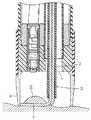
図2は内視鏡の挿入部の先端部分の正面図であり、図1は、観察窓2の中心と処置具突出口3の中心とを含む内視鏡の挿入部の先端部分の側面断面図である。Embodiments of the present invention will be described with reference to the drawings.
FIG. 2 is a front view of the distal end portion of the insertion portion of the endoscope, and FIG. 1 is a side cross-sectional view of the distal end portion of the insertion portion of the endoscope including the center of the
挿入部の最先端部材である略円柱状の先端部本体1の先端面1aには、先端部本体1の前方を観察するための観察窓2と処置具類を突出させるための処置具突出口3とが並んで配置され、その他にも、照明窓4等が配置されている。 An
そして、観察窓2の奥には対物光学系5が配置され、その対物光学系5による被写体の投影位置に固体撮像素子6が配置されている。また、処置具突出口3の奥には、挿入部内に全長にわたって挿通配置されている処置具挿通チャンネル7の先端開口が連通配置されている。 An objective
例えば透明なアクリル樹脂やポリカーボネート樹脂等のような透明樹脂によって先端部本体1の外径と略同程度の径の略円筒状に形成された先端フード10の基端側には、弾力性のあるゴム材等によって内径寸法が先端部本体1の外径寸法より小さな円筒状に形成された弾力環11が溶着等によって一体に連結されている。 For example, the proximal end side of the
弾力環11は弾性変形させることによって先端部本体1に対して被脱自在であり、弾力環11で先端部本体1の外周面を締め付ける状態にすることにより先端フード10が先端部本体1に取り付けられ、弾力環11を先端部本体1から取り外せばそれと共に先端フード10も外される。ただし、先端部本体1に対する先端フード10の着脱は、係合突起と溝等各種の構造を採用することができる。 The
先端フード10には、処置具突出口3内に前方から嵌め込まれて、処置具突出口3から突出される処置具を観察窓2から遠ざかる方向に偏角させるように案内する処置具案内孔13が形成された処置具案内部12が、一体成形されている。 A treatment
処置具案内部12には、処置具突出口3内に嵌め込まれる部分12aと先端フード10(即ち、略円筒状の突出部)との間を先端部本体1の先端面1aに沿う位置で連結する連結部12bが形成されており、連結部12bは観察窓2からの観察視野範囲VF外に位置している。 The treatment
そして処置具案内孔13は、処置具案内部12の処置具突出口3内に嵌め込まれる部分12aと連結部12bとにまたがって、前方へ行くほど観察窓2の観察光軸から遠ざかる方向に偏角して形成されている。 The treatment
そのような処置具案内孔13は、処置具突出口3の径より細い径に形成されて処置具突出口3の観察窓2から最も遠い稜線位置Aで処置具突出口3と滑らかにつながっており、処置具突出口3の内周面に対して段差ができないよう、処置具突出口3内に位置する処置具案内孔13の稜線部分は全て滑らかにテーパ面取りされている。 Such a treatment
図3は、本実施例の先端フード10が取り付けられた内視鏡を用いて経内視鏡的粘膜切除術を施行している状態を示しており、先端フード10の内側に位置する患部粘膜100が観察窓2を通して観察され、先端フード10の周囲の状態も透明な先端フード10を通して観察される。 FIG. 3 shows a state in which transendoscopic mucosal resection is performed using an endoscope to which the
そして、処置具挿チャンネル7を通過した高周波スネア50は、先端フード10の処置具案内孔13内を通過することによって観察窓2から遠ざかる方向に偏角して、先端フード10の最先端部分では先端フード10の外縁部に近づく。 Then, the high-
その結果、高周波スネア50の先端から側方に折れ曲がった状態に突出する先端ループ電極51を、先端フード10の内部空間いっぱいに大きく広げて患部粘膜100に引っ掛け、先端ループ電極51に高周波電流を通電して患部粘膜100を広い範囲で切除することができる。 As a result, the
また、処置具案内孔13の径が処置具突出口3の径より小さく形成されていることにより、そこを通過する可撓性シース52のガタつきが小さいので、所望の患部粘膜100を確実にねらって誘導し、先端ループ電極51で容易に切除処置することができる。 In addition, since the diameter of the treatment
1 先端部本体
1a 先端面
2 観察窓
3 処置具突出口
10 先端フード
12 処置具案内部
12a 処置具突出口内に嵌め込まれる部分
12b 連結部
13 処置具案内孔
50 高周波スネア(処置具)
51 先端ループ電極
52 可撓性シースDESCRIPTION OF
51 Tip Loop Electrode 52 Flexible Sheath
Claims (4)
Translated fromJapanese上記処置具突出口内に前方から嵌め込まれて上記処置具突出口から突出される処置具を上記観察窓から遠ざかる方向に偏角させるように案内する処置具案内部が一体的に形成されていることを特徴とする内視鏡の先端フード。An inner part that is detachably attached to the distal end body so as to project forward in a substantially cylindrical shape from the distal end surface of the distal end body of the endoscope insertion portion in which the observation window and the treatment instrument projection opening are arranged side by side. In the tip hood of the endoscope,
A treatment instrument guide portion that is fitted from the front into the treatment instrument projection opening and guides the treatment instrument projected from the treatment instrument projection opening so as to deviate in a direction away from the observation window is integrally formed. Endoscope hood characterized by
Priority Applications (1)
| Application Number | Priority Date | Filing Date | Title |
|---|---|---|---|
| JP2003316130AJP4349870B2 (en) | 2003-09-09 | 2003-09-09 | Endoscope tip hood |
Applications Claiming Priority (1)
| Application Number | Priority Date | Filing Date | Title |
|---|---|---|---|
| JP2003316130AJP4349870B2 (en) | 2003-09-09 | 2003-09-09 | Endoscope tip hood |
Publications (2)
| Publication Number | Publication Date |
|---|---|
| JP2005080866Atrue JP2005080866A (en) | 2005-03-31 |
| JP4349870B2 JP4349870B2 (en) | 2009-10-21 |
Family
ID=34416124
Family Applications (1)
| Application Number | Title | Priority Date | Filing Date |
|---|---|---|---|
| JP2003316130AExpired - Fee RelatedJP4349870B2 (en) | 2003-09-09 | 2003-09-09 | Endoscope tip hood |
Country Status (1)
| Country | Link |
|---|---|
| JP (1) | JP4349870B2 (en) |
Cited By (3)
| Publication number | Priority date | Publication date | Assignee | Title |
|---|---|---|---|---|
| WO2006112231A1 (en)* | 2005-04-14 | 2006-10-26 | Olympus Corporation | Attachment for endoscope, treatment instrument for endoscope, and endoscope system |
| WO2010116745A1 (en)* | 2009-04-10 | 2010-10-14 | 住友ベークライト株式会社 | Endoscope hood and endoscope having same mounted thereon |
| JP2012095917A (en)* | 2010-11-04 | 2012-05-24 | Fujifilm Corp | Attachment for endoscope, and endoscope system |
- 2003
- 2003-09-09JPJP2003316130Apatent/JP4349870B2/ennot_activeExpired - Fee Related
Cited By (9)
| Publication number | Priority date | Publication date | Assignee | Title |
|---|---|---|---|---|
| WO2006112231A1 (en)* | 2005-04-14 | 2006-10-26 | Olympus Corporation | Attachment for endoscope, treatment instrument for endoscope, and endoscope system |
| JP2006288941A (en)* | 2005-04-14 | 2006-10-26 | Olympus Corp | Attachment for endoscope, treating tool for endoscope and endoscope system |
| US8357082B2 (en) | 2005-04-14 | 2013-01-22 | Olympus Corporation | Endoscopic attachment, endoscopic treatment instrument, and endoscope system |
| EP1870015B1 (en)* | 2005-04-14 | 2018-05-02 | Olympus Corporation | Attachment for endoscope, treatment instrument for endoscope, and endoscope system |
| WO2010116745A1 (en)* | 2009-04-10 | 2010-10-14 | 住友ベークライト株式会社 | Endoscope hood and endoscope having same mounted thereon |
| JP5621766B2 (en)* | 2009-04-10 | 2014-11-12 | 住友ベークライト株式会社 | Endoscope |
| US9072443B2 (en) | 2009-04-10 | 2015-07-07 | Sumitomo Bakelite Co., Ltd. | Endoscope hood and endoscope with the same mounted thereon |
| JP2012095917A (en)* | 2010-11-04 | 2012-05-24 | Fujifilm Corp | Attachment for endoscope, and endoscope system |
| US8939896B2 (en) | 2010-11-04 | 2015-01-27 | Fujifilm Corporation | Attachment for endoscope and endoscope system |
Also Published As
| Publication number | Publication date |
|---|---|
| JP4349870B2 (en) | 2009-10-21 |
Similar Documents
| Publication | Publication Date | Title |
|---|---|---|
| JP3533163B2 (en) | Endoscope tip | |
| JP4266743B2 (en) | Endoscopic hood and endoscopic mucosal resection tool | |
| US6916284B2 (en) | Endoscope hood | |
| US8357082B2 (en) | Endoscopic attachment, endoscopic treatment instrument, and endoscope system | |
| KR20050021244A (en) | Endoscope hood | |
| JPH114800A (en) | Endoscope tip | |
| JP2007260381A (en) | Ultrasound endoscope | |
| JP2006280602A (en) | Endoscope | |
| JP2001095752A (en) | Angle part of endoscope | |
| US20210068616A1 (en) | Endoscope and endoscope system | |
| JP4349870B2 (en) | Endoscope tip hood | |
| JP2006325816A (en) | Hood for endoscope | |
| JP2002233491A (en) | Endoscope endoscope with tip cap | |
| JP3791910B2 (en) | Endoscope hood | |
| WO2019102679A1 (en) | Endoscope tip and endoscope | |
| JPH09220192A (en) | Endoscope | |
| JP2002301010A (en) | Hooded endoscope tip | |
| JP3934209B2 (en) | Endoscope hood device for endoscope | |
| JP4794961B2 (en) | Endoscope hood | |
| JP5017548B2 (en) | End of the endoscope | |
| JP4996440B2 (en) | Endoscopic high-frequency treatment instrument | |
| US4784119A (en) | Insertion assembly of an endoscope | |
| JP2001286434A (en) | Tip of side-viewing type endoscope | |
| JP4794962B2 (en) | Endoscope hood | |
| WO2019230084A1 (en) | Distal hood |
Legal Events
| Date | Code | Title | Description |
|---|---|---|---|
| A621 | Written request for application examination | Free format text:JAPANESE INTERMEDIATE CODE: A621 Effective date:20060719 | |
| A711 | Notification of change in applicant | Free format text:JAPANESE INTERMEDIATE CODE: A712 Effective date:20080501 | |
| A977 | Report on retrieval | Free format text:JAPANESE INTERMEDIATE CODE: A971007 Effective date:20090701 | |
| TRDD | Decision of grant or rejection written | ||
| A01 | Written decision to grant a patent or to grant a registration (utility model) | Free format text:JAPANESE INTERMEDIATE CODE: A01 Effective date:20090716 | |
| A01 | Written decision to grant a patent or to grant a registration (utility model) | Free format text:JAPANESE INTERMEDIATE CODE: A01 | |
| A61 | First payment of annual fees (during grant procedure) | Free format text:JAPANESE INTERMEDIATE CODE: A61 Effective date:20090721 | |
| FPAY | Renewal fee payment (event date is renewal date of database) | Free format text:PAYMENT UNTIL: 20120731 Year of fee payment:3 | |
| R150 | Certificate of patent or registration of utility model | Free format text:JAPANESE INTERMEDIATE CODE: R150 | |
| FPAY | Renewal fee payment (event date is renewal date of database) | Free format text:PAYMENT UNTIL: 20120731 Year of fee payment:3 | |
| FPAY | Renewal fee payment (event date is renewal date of database) | Free format text:PAYMENT UNTIL: 20130731 Year of fee payment:4 | |
| LAPS | Cancellation because of no payment of annual fees |