JP2005080720A - Bioelectrical impedance measuring device - Google Patents
Bioelectrical impedance measuring deviceDownload PDFInfo
- Publication number
- JP2005080720A JP2005080720AJP2003313381AJP2003313381AJP2005080720AJP 2005080720 AJP2005080720 AJP 2005080720AJP 2003313381 AJP2003313381 AJP 2003313381AJP 2003313381 AJP2003313381 AJP 2003313381AJP 2005080720 AJP2005080720 AJP 2005080720A
- Authority
- JP
- Japan
- Prior art keywords
- voltage
- impedance
- component
- living body
- bioelectrical impedance
- Prior art date
- Legal status (The legal status is an assumption and is not a legal conclusion. Google has not performed a legal analysis and makes no representation as to the accuracy of the status listed.)
- Pending
Links
Images


Classifications
- A—HUMAN NECESSITIES
- A61—MEDICAL OR VETERINARY SCIENCE; HYGIENE
- A61B—DIAGNOSIS; SURGERY; IDENTIFICATION
- A61B5/00—Measuring for diagnostic purposes; Identification of persons
- A61B5/05—Detecting, measuring or recording for diagnosis by means of electric currents or magnetic fields; Measuring using microwaves or radio waves
- A61B5/053—Measuring electrical impedance or conductance of a portion of the body
- A61B5/0537—Measuring body composition by impedance, e.g. tissue hydration or fat content
Landscapes
- Health & Medical Sciences (AREA)
- Life Sciences & Earth Sciences (AREA)
- Biomedical Technology (AREA)
- Heart & Thoracic Surgery (AREA)
- Radiology & Medical Imaging (AREA)
- Biophysics (AREA)
- Pathology (AREA)
- Engineering & Computer Science (AREA)
- Nuclear Medicine, Radiotherapy & Molecular Imaging (AREA)
- Physics & Mathematics (AREA)
- Medical Informatics (AREA)
- Molecular Biology (AREA)
- Surgery (AREA)
- Animal Behavior & Ethology (AREA)
- General Health & Medical Sciences (AREA)
- Public Health (AREA)
- Veterinary Medicine (AREA)
- Measurement And Recording Of Electrical Phenomena And Electrical Characteristics Of The Living Body (AREA)
Abstract
Translated fromJapaneseDescription
Translated fromJapanese本発明は、生体電気インピーダンスを測定して身体の組成を算出する装置における電極の接触状態を判定する技術に関するものである。 The present invention relates to a technique for determining a contact state of an electrode in an apparatus for measuring a bioelectrical impedance and calculating a body composition.
生体電気インピーダンスを測定し、体内の脂肪を算出する装置がある。この測定方法としては主に4端子法と呼ばれる測定法が用いられている。 There are devices that measure bioelectrical impedance and calculate fat in the body. As this measuring method, a measuring method called a four-terminal method is mainly used.
この生体電気インピーダンス測定の4端子法について説明すると、測定者の両手または両足といった部位間の身体内のインピーダンスを測定し、その測定値から体脂肪量、筋肉量、体水分量などを統計的に推定するものである。 The 4-terminal method of bioelectrical impedance measurement will be described. The body impedance between parts such as both hands or feet of the measurer is measured, and the body fat mass, muscle mass, body water content, etc. are statistically determined from the measured values. To be estimated.
体重測定と共に、体脂肪率を測定する体重計付き体脂肪計が知られているが、両足間における生体電気インピーダンスを測定する場合には、装置の上面に設けられた足用電極に測定者の足の裏を接触させるように装置に載り、測定を行うものである。 A body fat scale with a weight scale that measures body fat percentage is known together with body weight measurement, but when measuring bioelectric impedance between both feet, the electrode of the foot provided on the upper surface of the apparatus is It is placed on the device so that the soles of the feet are in contact with each other for measurement.
このような測定法では、電極と皮膚表面とが充分な接触が確保されている場合には、問題なく測定できるものであるが、不十分な接触状況の場合には、皮膚表面と電極との間に高い接触インピーダンスが生じ、正確な測定が行われない場合がある。 In such a measurement method, when the electrode and the skin surface are sufficiently in contact with each other, measurement can be performed without any problem. However, in the case of insufficient contact, the skin surface and the electrode are in contact with each other. In some cases, a high contact impedance is generated between them, and accurate measurement may not be performed.
このような問題点の対策として、電極と測定者との接触状態をチェックする方法が多数提案されている。 As a countermeasure against such problems, many methods for checking the contact state between the electrode and the measurer have been proposed.
電流印加電極A1,A2と電圧測定電極B1,B2との間にそれぞれ測定精度に影響を与えない程度の値を持つ抵抗Ra,Rbを接続し、接触インピーダンスが高い場合には、定電流回路から電圧測定回路入力に大きいクランプ電圧を加えることで、身体内のインピーダンスに発生する測定電圧と判定できることとし、これにより誤測定を防止するものである。つまり、接触インピーダンスが適正な値であるかにより、接触状態を判定している(例えば、特許文献1)。 When the resistors Ra and Rb having values that do not affect the measurement accuracy are connected between the current application electrodes A1 and A2 and the voltage measurement electrodes B1 and B2, respectively, the contact current is high. By applying a large clamp voltage to the input of the voltage measurement circuit, it can be determined that the measurement voltage is generated in the impedance in the body, thereby preventing erroneous measurement. That is, the contact state is determined based on whether the contact impedance is an appropriate value (for example, Patent Document 1).
また、接触インピーダンスの大きさを判定することにより、測定状態の適否を判定するものもある(例えば、特許文献2)。 In addition, there is one that determines the suitability of the measurement state by determining the magnitude of the contact impedance (for example, Patent Document 2).
また、充分な接触状態が得られやすいように、測定時に接触させる電極内部に計測開始スイッチを設ける技術が提案されている。これにより正しい測定姿勢・接触状態が得られるとしている(例えば、特許文献3)。 In addition, a technique has been proposed in which a measurement start switch is provided inside an electrode to be contacted during measurement so that a sufficient contact state can be easily obtained. Thereby, a correct measurement posture / contact state is obtained (for example, Patent Document 3).
また、生体電気インピーダンス測定に用いる全ての電極を電流供給電極として、各電極の接続を切り替えながら定電流Iを流すことで、接触抵抗を含む身体内インピーダンス値と接触抵抗値を含む身体内インピーダンスのみを求める方法が提案されている(例えば、特許文献4)。 In addition, by using all the electrodes used for bioelectrical impedance measurement as current supply electrodes and passing constant current I while switching the connection of each electrode, only in-body impedance value including contact resistance and in-body impedance including contact resistance value Has been proposed (for example, Patent Document 4).
また、生体電気インピーダンス測定の測定電流経路に、測定される生体電気インピーダンス値を適当に分割し得る複数の既知抵抗値の基準抵抗群を生体と直列接続し、基準抵抗群の複数の抵抗値による電圧降下値と生体による電圧降下値を測定し、複数の抵抗値とそれに対応した複数の測定電圧値とにより両者間の相関式を決定し、測定によって得られた生体の測定電圧値と相関式を用いて生体電気インピーダンス値を求めるインピーダンス測定法が開示されている(例えば特許文献5)。
生体電気インピーダンス測定において、測定が確実に行われるためには、生体と電極との接触が良好でなければならない。そのため、背景技術に示したように、従来から生体電気インピーダンス測定における電極の接触状態をチェックする方法が提案されているが、それらは、測定しようとする部位の生体電気インピーダンスの測定とは別に、チェックを行うものである。つまり、両足間の測定をするために、足の裏と電極との接触インピーダンスを測定し、その結果が良好であれば、接触状態は正常として両足間の生体電気インピーダンスを測定するものである。そのため、測定までに、幾つかの判定処理を行うことになり、結果的に測定時間が長いものとなる。 In the bioelectrical impedance measurement, in order for the measurement to be performed reliably, the contact between the living body and the electrode must be good. Therefore, as shown in the background art, a method for checking the contact state of the electrode in bioelectrical impedance measurement has been proposed conventionally, but apart from the measurement of the bioelectrical impedance of the part to be measured, Check. That is, in order to measure between both feet, the contact impedance between the sole of the foot and the electrode is measured, and if the result is good, the contact state is normal and the bioelectrical impedance between both feet is measured. For this reason, several determination processes are performed before the measurement, resulting in a long measurement time.
そのため一般的に実際に行われている電極の接触状態の判定法は、測定された生体電気インピーダンスの絶対値が、ある値以内に収まっているか否かで接触状態が十分であるか、あるいはショートしている可能性があるかを判定している。 Therefore, in general, the actual method of determining the contact state of the electrode is that the contact state is sufficient depending on whether or not the absolute value of the measured bioelectrical impedance is within a certain value, or a short circuit. Judging whether there is a possibility of being.
しかし、充分な接触が得られていない状況でも、測定可能な状況と誤認識し、測定が実行されてしまうことがあった。 However, even in a situation where sufficient contact has not been obtained, the situation may be erroneously recognized as being measurable and measurement may be performed.
図9は、生体電気インピーダンス測定部のブロック図を示すものである。 FIG. 9 is a block diagram of the bioelectrical impedance measuring unit.
ZRは、背景技術に示したインピーダンス測定法(特許第2835656号公報参照)における複数の既知抵抗値の基準抵抗群にあたる基準インピーダンスであり、ZBは測定する生体のインピーダンスである。a,bが電流供給電極、c,dが電圧測定電極である。icは測定電流である。ZR is the reference impedance corresponding to the reference resistor group of a plurality of known resistance values in the impedance measurement method shown in the background art (see Japanese Patent No. 2835656), the impedance of the living body ZB is to be measured. a and b are current supply electrodes, and c and d are voltage measurement electrodes. ic is a measured current.
通常、測定時には測定電流icは、基準インピーダンスZR、生体インピーダンスZB共に問題なく流れ、それぞれの複素電圧VR、VBともに測定可能である。Usually, at the time of measurement, the measurement current ic flows without any problem in both the reference impedance ZR and the bioimpedance ZB and can measure both the complex voltages VR and VB.
仮に電流供給電極a,bのどちらかあるいは両方ともに、生体が正常に接触していない場合には、測定回路はオープン状態となりVRもVBも0となり測定不可能である。この時、アンプの同相入力除去特性(CMRR)に応じた極小さな電圧が測定結果として得られ、理想的には0となる。If the current supply electrodes a, in either or both of b, and if the living body is not in normal contact with the measuring circuit is also becomes VR and open VB is also zero unmeasurable. At this time, a very small voltage corresponding to the common-mode input rejection characteristic (CMRR) of the amplifier is obtained as a measurement result and ideally becomes zero.
また、電圧測定電極c,dのどちらかあるいは両方とも生体に正常に接触していない場合には、VRは測定できるものの、VBは測定不可となり値が定まらない。Further, the voltage measuring electrodes c, when the living body with either or both of d not normally contact, although VR can be measured, VB is unmeasurable and will value not determined.
このような場合のチェックとして、200Ω<|Z|<1000Ωのようにインピーダンスの適正範囲を設けることで、電極の接触状態を判定しているが、場合によっては200Ωを少し越えた位の値で安定してしまうことがあった。 As a check in such a case, the contact state of the electrode is determined by providing an appropriate impedance range such that 200Ω <| Z | <1000Ω, but in some cases, the value is slightly over 200Ω. It sometimes became stable.
これは現実にはアンプの保護回路(静電気対策のダイオードなど)や浮遊容量(電極間容量など)によって、接触が不良な端子の電圧が生じてしまっていたためであると考えられる。例えば、図9(b)に示すように電圧測定電極cがオープンの場合(接触不良の場合)、電圧測定電極cとdの間に電極間容量が生じ、本来測定されない電圧が発生していると考えられる。従って接触が不良な状況であっても、従来のインピーダンス値の適正範囲による接触判定法では、正常範囲に収まっているために誤判定して、そのまま測定を継続し、誤った演算結果を表示してしまうことがあった。 This is considered to be due to the fact that the voltage of the terminal with poor contact was generated by the amplifier protection circuit (such as a diode for preventing static electricity) and stray capacitance (such as the capacitance between electrodes). For example, as shown in FIG. 9B, when the voltage measurement electrode c is open (in the case of contact failure), an interelectrode capacitance is generated between the voltage measurement electrodes c and d, and a voltage that is not originally measured is generated. it is conceivable that. Therefore, even if the contact is poor, the conventional contact judgment method based on the appropriate range of impedance values makes a misjudgment because it is within the normal range, continues measurement, and displays the incorrect calculation result. There was a case.
本発明はこのような問題点を鑑みてなされるものであり、生体電気インピーダンス測定において、測定時に用いる電極と生体との接触が正常であるかをより正確に判定することであり、それにより、正確な生体電気インピーダンス測定を行うことができる装置を提供することである。 The present invention is made in view of such problems, and in bioelectrical impedance measurement, it is to determine more accurately whether the contact between the electrode used at the time of measurement and the living body is normal. An object of the present invention is to provide an apparatus capable of performing accurate bioelectrical impedance measurement.
本発明は生体に接触する電極を含む生体電気インピーダンスを測定するためのインピーダンス測定手段を備える生体電気インピーダンス測定装置において、
生体の位相差に関するパラメータを用いて前記電極と生体との接触状態を判定する判定手段を備えることとする。The present invention relates to a bioelectrical impedance measuring device including an impedance measuring means for measuring bioelectrical impedance including an electrode that contacts a living body,
Suppose that the determination means which determines the contact state of the said electrode and a biological body using the parameter regarding the phase difference of a biological body is provided.
また、本発明の生体電気インピーダンス測定装置では、前記インピーダンス測定手段において測定される生体電気インピーダンスにおける抵抗成分をR、リアクタンス成分をXとすると、前記生体の位相差に関するパラメータはX/Rで示される値を用いることとする。 In the bioelectrical impedance measuring apparatus of the present invention, when the resistance component in the bioelectrical impedance measured by the impedance measuring means is R and the reactance component is X, the parameter relating to the phase difference of the living body is represented by X / R. The value will be used.
また、本発明の生体電気インピーダンス測定装置では、前記判定手段における接触判定の条件は、
a<X/R<b
(但しa,bは実数)
であることとする。Moreover, in the bioelectrical impedance measuring apparatus of the present invention, the contact determination condition in the determination means is:
a <X / R <b
(Where a and b are real numbers)
Suppose that
また、本発明の生体電気インピーダンス測定装置では、前記判定手段は、位相差に関するパラメータを用いて電極と生体との接触状態を判定する前に、更に前記インピーダンス測定手段で測定される生体電気インピーダンスの抵抗成分に関するパラメータが正の値であるかを判定することで接触状態を判定することとする。 In the bioelectrical impedance measuring apparatus of the present invention, the determination unit may further determine the bioelectrical impedance measured by the impedance measurement unit before determining the contact state between the electrode and the living body using a parameter relating to the phase difference. The contact state is determined by determining whether the parameter relating to the resistance component is a positive value.
また、本発明の生体電気インピーダンス測定装置では、前記抵抗成分に関するパラメータは真のインピーダンスの抵抗成分を表す真インピーダンス成分変数であることとする。 In the bioelectrical impedance measuring apparatus according to the present invention, the parameter relating to the resistance component is a true impedance component variable representing the resistance component of the true impedance.
また、本発明の生体電気インピーダンス測定装置では、前記抵抗成分に関するパラメータは抵抗成分に基因する電圧を表す実測電圧変数であることとする。 In the bioelectrical impedance measuring apparatus of the present invention, the parameter relating to the resistance component is an actually measured voltage variable representing a voltage caused by the resistance component.
本発明の生体電気インピーダンス測定装置では、生体電気インピーダンスの測定時に使用する電極と生体との接触状態の判定において、生体の位相差に関するパラメータを用いるので、従来と比べてより正確に接触状態を判定することができる。これにより、生体電気インピーダンス値の測定は正確なものとなり、その生体電気インピーダンス値を用いて演算される体脂肪率や筋肉量といった体組成の値も正確なものとなる。 In the bioelectrical impedance measuring apparatus according to the present invention, the contact state between the electrode used when measuring the bioelectrical impedance and the living body is determined using a parameter related to the phase difference of the living body. can do. Thereby, the measurement of the bioelectrical impedance value becomes accurate, and the values of the body composition such as the body fat percentage and the muscle mass calculated using the bioelectrical impedance value become accurate.
また、本発明の生体電気インピーダンス測定装置では、生体電気インピーダンスの測定時に使用する電極と生体との接触状態の判定において、測定される生体電気インピーダンスにおける抵抗成分をR、リアクタンス成分をXとしたとき、X/Rで示される値を判定に用いるが、この値は電極の接触が異常な場合には、生体のその値とは大きくかけ離れた値を示すため、簡単に、かつ正確に接触状態を判定することが可能となる。 Further, in the bioelectrical impedance measuring apparatus of the present invention, when determining the contact state between the electrode used when measuring the bioelectrical impedance and the living body, the resistance component in the measured bioelectrical impedance is R and the reactance component is X. The value indicated by X / R is used for the determination, but when the contact of the electrode is abnormal, the value shows a value far from the value of the living body. It becomes possible to judge.
また、本発明の生体電気インピーダンス測定装置では、a<X/R<b(ただし、a,bは実数)という条件を設け、算出された値がその範囲内であるかにより接触状態の判定を行うので、その範囲外の場合には接触不良であると簡単に接触状態の判定を行うことができる。 In the bioelectrical impedance measuring apparatus of the present invention, the condition of a <X / R <b (where a and b are real numbers) is provided, and the contact state is determined depending on whether the calculated value is within the range. Therefore, if the contact is out of the range, the contact state can be easily determined as a contact failure.
また、本発明の生体電気インピーダンス測定装置では、更に位相差に関するパラメータを用いて電極と生体との接触状態を判定する前に、測定される生体電気インピーダンスの抵抗成分に関するパラメータが正の値であるかを判定するので、位相差に関するパラメータを用いた電極と生体との接触チェックの演算を行うまでもなく、接触の異常をチェックすることが可能となる。 In the bioelectrical impedance measuring device of the present invention, the parameter relating to the resistance component of the bioelectrical impedance to be measured is a positive value before determining the contact state between the electrode and the living body using the parameter relating to the phase difference. Therefore, it is possible to check the contact abnormality without performing the calculation of the contact check between the electrode and the living body using the parameter relating to the phase difference.
また、本発明の生体電気インピーダンス測定装置では、測定される生体電気インピーダンスの抵抗成分に関するパラメータに真のインピーダンスの抵抗成分を表す真インピーダンス成分変数RBを用いるので、位相差に関するパラメータを用いた電極と生体との接触チェックの演算を行うまでもなく、真インピーダンス成分変数RBが演算された時点で接触状態を判定でき、ここで接触不良の判定の場合には、この時点で位相差に関するパラメータを用いた判定結果が解り、接触状態の判定に要する時間を大幅に削減できる。Further, in the bioelectrical impedance measuring apparatus of the present invention uses a true impedance component variable RB of the parameters related to the resistance component of the bioelectrical impedance measured represents the resistance component of a true impedance, electrode using a parameter associated with the phase difference and without performing computation of the contact check with the biological, can determine the contact state when the true impedance component variable RB are computed, in the case of the determination of poor contact here, parameters related to the phase difference at this point As a result, the time required for determining the contact state can be greatly reduced.
また、本発明の生体電気インピーダンス測定装置では、測定される生体電気インピーダンスの抵抗成分に関するパラメータに抵抗成分に基因する電圧を表す実測電圧変数VBRを用いるので、位相差に関するパラメータを用いた電極と生体との接触チェックの演算をするまでもなく、生体において測定された電圧値そのものの値から接触状態を判定でき、ここで接触不良の判定の場合には、この時点で位相差に関するパラメータを用いた判定結果が解り、接触状態の判定に要する時間を大幅に削減できる。Further, in the bioelectrical impedance measuring apparatus of the present invention uses the measured voltage variable VBR representing the voltage attributed to the parameter to the resistance component regarding the resistance component of the bioelectrical impedance to be measured, the electrode using the parameter associated with the phase difference The contact state can be determined from the voltage value itself measured in the living body without calculating the contact check with the living body. In the case of a contact failure determination, a parameter relating to the phase difference is used at this time. As a result, the time required for determining the contact state can be greatly reduced.
本発明の生体電気インピーダンス測定装置では、生体電気インピーダンスの測定時に使用する電極と生体との接触状態の判定に、位相差に関するパラメータを用いることで、従来から行われている判定法よりも正確に接触状態を判定することとする。 In the bioelectrical impedance measuring apparatus of the present invention, a parameter relating to the phase difference is used for determining the contact state between the electrode used for measuring the bioelectrical impedance and the living body, thereby more accurately than the conventional determination method. The contact state is determined.
この位相差に関するパラメータとしては、測定される生体電気インピーダンスにおける抵抗(レジスタンス)成分をR、リアクタンス成分をXとしたとき、X/Rで示される値を用い、条件として、a<X/R<b(ただし、a,bは実数)といった判定条件を設けて、この範囲外のときには、電極と生体との接触が異常であると判定する。 As a parameter relating to this phase difference, when the resistance (resistance) component in the measured bioelectrical impedance is R and the reactance component is X, a value indicated by X / R is used, and the condition is a <X / R < A determination condition such as b (where a and b are real numbers) is provided, and when it is outside this range, it is determined that the contact between the electrode and the living body is abnormal.
また、位相差の関するパラメータを用いた接触状態の判定に加え、測定される生体電気インピーダンスの抵抗成分に関するパラメータが正の値であるかを判定するものとする。このチェックにおいて値が負である場合には、後の位相差に関するパラメータを用いた接触状態の判定において、接触不良と判定されることが決まっており、従って、この生体電気インピーダンスの抵抗成分に関するパラメータの正負の判定だけでも、接触不良を判定することができる。ここで用いる生体電気インピーダンスの抵抗成分に関するパラメータは真のインピーダンスの抵抗成分を表す真インピーダンス成分変数RBでよく、また、抵抗成分に基因する電圧を表す実測電圧変数VBRでもよい。Further, in addition to the determination of the contact state using the parameter related to the phase difference, it is determined whether or not the parameter related to the resistance component of the measured bioelectric impedance is a positive value. If the value is negative in this check, it is determined that contact failure is determined in the subsequent contact state determination using the parameter regarding the phase difference. Therefore, the parameter regarding the resistance component of this bioelectrical impedance is determined. The contact failure can be determined only by positive / negative determination. Here parameters related resistance component of a bioelectrical impedance used in may be a true impedance component variable RB representing the resistance component of a true impedance, also may be measured voltage variable VBR representing the voltage attributed to resistance component.
本発明の実施例を図面を用いて説明する。 Embodiments of the present invention will be described with reference to the drawings.
図1は本発明の生体電気インピーダンス測定装置を用いた体脂肪計のブロック図である。 FIG. 1 is a block diagram of a body fat scale using the bioelectrical impedance measuring apparatus of the present invention.
この体脂肪計内の生体電気インピーダンス測定装置は、ソフト的処理によって、実測される生体のインピーダンスを抵抗成分とリアクタンス成分とに分離して、生体のより正確なインピーダンスを求めるものである。 This bioelectrical impedance measuring device in the body fat scale is configured to separate the actually measured impedance of the living body into a resistance component and a reactance component by a software process to obtain a more accurate impedance of the living body.
体脂肪計は、測定手段1と記憶部2と、マイコン3と、表示部4とを備える。 The body fat scale includes a measuring
測定手段1においては、生体5、外部基準器6又は内部基準器7についてのインピーダンスに基因する電圧を測定する。そして、この測定手段1は、定電圧(正弦波交流)発生器8、電圧/電流変換器9、内部基準器7、電極A10、電極B11、切替器12、増幅器13、フィルタ14及びA/D変換器(同期検波方式)15から成る。 In the measuring means 1, the voltage caused by the impedance of the living
定電圧(正弦波交流)発生器8は、高周波(例えば50kHz)の定電圧を発生し、電圧/電流変換器9に出力する。電圧/電流変換器9は、定電圧(正弦波交流)発生器8から受けた定電圧を定電流に変換し、内部基準器7に出力する。 The constant voltage (sine wave alternating current)
内部基準器7は、環境等の温度変化の原因により、定電圧(正弦波交流)発生器8や電圧/電流変換器9からの定電流の変化がもたらすインピーダンスの影響を補正するための基準となるインピーダンスである。この内部基準器7は、従来の技術で引用したインピーダンス測定法(特許第2835656号公報参照)における複数の既知抵抗値の基準抵抗群にあたるものである。本件においては、この内部基準器7には、一つの既知基準抵抗を用いる。 The
電極A10は、電圧/電流変換器9から内部基準器7を経た定電流を生体5又は外部基準器6に発生する電圧を検出するための端子である。 The electrode A <b> 10 is a terminal for detecting a voltage that generates a constant current from the voltage / current converter 9 through the
切替器12は、定電流が内部基準器7に流れたことにより内部基準器7に発生する電圧と、定電流が2つの電極B11間の生体5又は外部基準器6に流れたことにより2つの電極B11間に発生する電圧との検出を切り替える。 The
増幅器13は、切替器12を経た内部基準器7のインピーダンスに基因する電圧、又は生体5若しくは外部基準器6のインピーダンスに基因する電圧を増幅する。フィルタ14は、増幅器13で増幅された電圧のノイズ成分を除去する。 The
A/D変換器(同期検波方式)15は、フィルタ14でノイズ成分が除去された電圧(アナログ)をデジタル変換すると共に、定電圧(正弦波交流)発生器8からの正弦波発生のタイミング信号に基づいて、内部基準器7又は生体5若しくは外部基準器6の抵抗成分に基因する電圧とリアクタンス成分に基因する電圧とに分離してマイコン3に出力する。 The A / D converter (synchronous detection method) 15 digitally converts the voltage (analog) from which the noise component has been removed by the
記憶部2においては、演算式記憶手段17及び変動定数記憶手段18を有すると共に、各種演算の際の一時的な記憶その他の公知の如き記憶を行う。なお、記憶部2には、EEPROMを用いる。 The
演算式記憶手段17は、測定手段1に生じるインピーダンス変動要因に基づく変動を表す変動変数と、実測によるインピーダンスの抵抗成分に基因する電圧及びリアクタンス成分に基因する電圧を表す実測電圧変数とに、生体5又は外部基準器6の真のインピーダンスの抵抗成分及びリアクタンス成分を表す真インピーダンス変数を対応させたインピーダンス演算式を予め記憶する。 The arithmetic expression storage means 17 includes a variable variable representing a fluctuation based on an impedance fluctuation factor generated in the measurement means 1, a voltage caused by a resistance component of impedance measured actually, and a measured voltage variable representing a voltage caused by a reactance component. 5 or an external reference unit 6 is stored in advance with an impedance calculation formula that associates the true impedance variable representing the resistance component and reactance component of the true impedance.
なお、インピーダンス演算式は、測定手段1に生じるインピーダンス変動要因に基づく変動を考慮した図2の測定手段1における回路モデルに基づいて後述する数1の式である。 The impedance calculation formula is a
図2の各部は、測定手段1に生じる位相変動成分をH(θ)、電圧/電流変換器9のインピーダンスをZi、内部基準器7のインピーダンスをZR、浮遊容量等によるインピーダンスをZS、生体5又は外部基準器6のインピーダンスをZB、内部基準器7と生体5(又は外部基準器6)とにかけて生ずる電圧をVO、内部基準器7のインピーダンス成分で生ずる電圧をVR、生体5又は外部基準器6のインピーダンス成分で生ずる電圧をVBで表す。Those in FIG. 2, the phase fluctuation component occurring in the measurement means 1 H (theta), the voltage / impedance of the current transformer 9 Zi, the impedance of the internal reference unit 7 ZR, the impedance due to the stray capacitance or the like ZS , The impedance of the living
この回路モデルによると、生体5又は外部基準器6のインピーダンスは、ZB=VB(1−ZR/ZS)ZR/VR=CVB/VRの式となる。ここでCは、スケールファクター及び位相に基づく変動を表す変動変数となる。そして、この式に、主にZSに起因するオフセット電圧に基づく変動を表す変動変数VOSを考慮すると共に、各変数を抵抗成分及びリアクタンス成分に分解する(ZBを生体5又は外部基準器6の真のインピーダンスの抵抗成分を表す真インピーダンス成分変数RBとリアクタンス成分を表す真インピーダンス成分変数XBとし、Cを抵抗成分のスケールファクター及び位相に基づく変動を表す変動変数CRとリアクタンス成分のスケールファクター及び位相に基づく変動を表す変動変数CXとし、VBを生体5又は外部基準器6の抵抗成分に基因する電圧を表す実測電圧変数VBRとリアクタンス成分に基因する電圧を表す実測電圧変数VBXとし、VRを内部基準器7の抵抗成分に基因する電圧を表す実測電圧変数VRRとリアクタンス成分に基因する電圧を表す実測電圧変数VRXとし、VOSを抵抗成分軸方向へのオフセット電圧に基づく変動を表す変動変数VOSRとリアクタンス成分軸方向に対するオフセット電圧に基づく変動を表す変動変数VOSXとする。)ことで数1の式が導かれる。According to this circuit model, the impedance of the living

この数1の式におけるスケールファクター及び位相に基づく変動を表す変動変数CR、CX、オフセット電圧に基づく変動を表す変動変数VOSR、VOSXは、測定手段1に生じるインピーダンス変動要因に基づく変動を表す変動変数に該当する。Variation variables CR , CX representing variation based on the scale factor and phase in
図3は、インピーダンスの抵抗成分及びリアクタンス成分の関係を座標に表す図である。縦軸Xはリアクタンス成分を、横軸Rは抵抗成分を、点Zはインピーダンスを、座標交点Oは零地点を、偏角θは位相差を表す。スケールファクター及び位相に基づく変動を示す変動変数CR、CXは、線分OZ方向の変動及び偏角θの変動についての変数を表し、オフセット電圧に基づく変動を表す変動変数VOSR、VOSXは、座標交点Oの変動についての変数を表すものである。FIG. 3 is a diagram illustrating the relationship between the resistance component and reactance component of the impedance in coordinates. The vertical axis X represents the reactance component, the horizontal axis R represents the resistance component, the point Z represents the impedance, the coordinate intersection O represents the zero point, and the declination θ represents the phase difference. The variable variables CR and CX indicating the fluctuation based on the scale factor and the phase represent variables regarding the fluctuation in the line segment OZ direction and the fluctuation of the deflection angle θ, and the variable variables VOSR and VOSX representing the fluctuation based on the offset voltage. Represents a variable about the change of the coordinate intersection point O.
変動定数記憶手段18は、後述する変動定数演算手段19で演算される変動定数を記憶する。 The fluctuation constant storage means 18 stores the fluctuation constant calculated by the fluctuation constant calculation means 19 described later.
マイコン3においては、分離手段16、変動定数演算手段19及び生体インピーダンス演算手段20を有する共に、定電圧(正弦波交流)発生器8からの高周波の定電圧の発生の制御その他の公知の如き制御を行う。また、図には記載しないが、一時的にデータを記憶するRAMや、一定時間を計測するタイマ機能といったマイコンの一般的な機能も備えるものである。 The
分離手段16は、A/D変換器15から出力されたインピーダンスに基因する電圧と、定電圧(正弦波交流)発生器8から発生される正弦波の周期と同じ又は90゜進む周期を時分割した振幅とに基づいて、内部基準器7又は生体5若しくは外部基準器6の実測による抵抗成分に基因する電圧とリアクタンス成分に基因する電圧とを演算する。 The separating means 16 time-divisions the voltage caused by the impedance output from the A / D converter 15 and the same period as the period of the sine wave generated from the constant voltage (sine wave alternating current)
変動定数演算手段19は、内部基準器7及び外部基準器6の測定によって分離手段16で演算により分離された抵抗成分に基因する電圧とリアクタンス成分に基因する電圧と、測定手段1で測定される外部基準器6のインピーダンスの既知の抵抗成分及びリアクタンス成分とに基づいて、演算式記憶手段17に予め記憶されるインピーダンス演算式(数1の式)から変動変数の定数である変動定数を演算する。 The variation constant calculating means 19 is measured by the measuring means 1 with the voltage caused by the resistance component and the voltage caused by the reactance component separated by the separation means 16 by the measurement of the
生体インピーダンス演算手段20は、変動定数記憶手段18で記憶される変動定数と、測定手段1で測定され、分離手段16で分離される生体5のインピーダンスの抵抗成分に基因する電圧及びリアクタンス成分に基因する電圧とを、演算式記憶手段17に予め記憶されるインピーダンス演算式(数1の式)に代入し、生体5の真のインピーダンスの抵抗成分及びリアクタンス成分を演算する。 The bioelectrical impedance calculating means 20 is based on the fluctuation constant stored in the fluctuation constant storage means 18 and the voltage and reactance components caused by the resistance component of the impedance of the living
表示部4は、生体インピーダンス演算手段20で演算された結果を表示する。 The
入力手段21は、体脂肪計に対してキー入力を行うものであり、設定スイッチ、測定スイッチ、数値スイッチといった複数のスイッチからなる。 The input means 21 performs key input to the body fat scale, and includes a plurality of switches such as a setting switch, a measurement switch, and a numerical switch.
次に本実施例に係わる体脂肪計の使用及び動作の流れについて、図4に示すフローチャートを参照して説明する。 Next, the flow of use and operation of the body fat scale according to this embodiment will be described with reference to the flowchart shown in FIG.
体脂肪計の電源がオンされると(ステップS1)、マイコン3からの制御により、各部の接続やRAMの値を初期化する(ステップS2)。 When the power of the body fat scale is turned on (step S1), the connection of each unit and the RAM value are initialized by the control from the microcomputer 3 (step S2).
ここで、表示部4には測定者の性別、身長、体重を入力するよう表示部4に表示される(ステップS3)。入力手段21の設定スイッチが押されると(ステップS4)、個人情報入力状態となり、測定者は数値スイッチを用いて性別、身長、体重といった個人情報を入力する(ステップS5)。 Here, the
ステップS4で設定スイッチが押されず、測定スイッチが押されると(ステップS6)、
生体インピーダンスの測定状態となると共に、マイコン内のタイマがスタートする(ステップS7)。この生体電気インピーダンス測定ルーチンについては後述する。If the setting switch is not pressed in step S4 and the measurement switch is pressed (step S6),
A bioimpedance measurement state is entered, and a timer in the microcomputer is started (step S7). This bioelectrical impedance measurement routine will be described later.
生体電気インピーダンスの測定が行われたら、その測定値から、電極と生体が正常に接触しているかを判定する、接触状態判定ルーチンになる(ステップS8)。この接触状態判定ルーチンについては後述する。 When the measurement of bioelectrical impedance is performed, a contact state determination routine for determining whether the electrode and the living body are in normal contact from the measured value is performed (step S8). This contact state determination routine will be described later.
接触状態判定ルーチンにおいて、接触状態が正常であったかを確認するために、接触正常回数を意味する接触正常回数iの値を確認し(ステップS9)、接触が不良であった場合には、生体電気インピーダンスの測定状態となってから30秒が経過したかを、マイコン3内のタイマからチェックする(ステップS10)。ここで30秒の経過前であれば、ステップS7の生体電気インピーダンス測定ルーチンへ戻り測定を継続し、30秒が経過している場合には、今回は正確な測定が行われなかったとし、表示部4にエラーを表示する(ステップS11)。 In the contact state determination routine, in order to confirm whether or not the contact state is normal, the value of the normal contact number i, which means the normal contact number, is checked (step S9). It is checked from the timer in the
ステップS9において接触状態が正常であった場合には、接触正常の判定が連続して6回起きたかを判定する。マイコン3内のRAMに記憶された接触正常回数を意味するiの値が6であるかをチェックし(ステップS12)、まだ6回未満であればステップS7に戻り生体電気インピーダンス測定を継続する。6回を超えている場合には、確実に接触状態が正常であると判断して、体脂肪率の計算を行い(ステップS13)、その結果を表示部4に表示する(ステップS14)。 If the contact state is normal in step S9, it is determined whether the determination of normal contact has occurred six times in succession. It is checked whether the value of i indicating the number of normal contacts stored in the RAM in the
ステップS11のエラー表示、及びステップS14の測定結果表示の後、一定時間が経過することで表示は消灯し、体脂肪計の電源も自動的にオフとなる(ステップS15)。 After the error display in step S11 and the measurement result display in step S14, the display is turned off when a predetermined time has elapsed, and the power of the body fat scale is automatically turned off (step S15).
次にステップS7の生体電気インピーダンス測定ルーチンについて説明する。
まず、図1に示すように、生体インピーダンスの測定範囲の下限に該当する既知のインピーダンス(例えば、R=100Ω、X=0Ω)である外部基準器6を電極A10及び電極B11に接続する(ステップS21)。Next, the bioelectrical impedance measurement routine in step S7 will be described.
First, as shown in FIG. 1, an external reference device 6 having a known impedance (eg, R = 100Ω, X = 0Ω) corresponding to the lower limit of the bioimpedance measurement range is connected to the electrode A10 and the electrode B11 (steps). S21).
続いて、マイコン3からの制御により定電圧(正弦波交流)発生器8から高周波(例えば、50kHz)の定電圧を発生し、電圧/電流変換器9でこの高周波の定電圧を定電流に変換し、内部基準器7へと出力する。次いで、切替器12を既知のインピーダンス(例えば、R=800Ω、X=0Ω)である内部基準器7側と接続し、この内部基準器7に生じる電圧を検出し、この電圧を増幅器13で増幅し、この増幅された電圧のノイズ成分をフィルタ14で除去し、この除去された電圧(アナログ)をA/D変換器15でデジタル信号に変換してマイコン3内の分離手段16に出力する。 Subsequently, a constant voltage (sine wave alternating current)
次いで、マイコン3内の分離手段16において、図5のフローチャートに示す処理を行い、内部基準器7の実測によるインピーダンスの抵抗成分に基因する電圧とリアクタンス成分に基因する電圧とを演算する(ステップS22)。 Next, the
このステップS22における処理を図6を用いてより具体的に詳述する。分離手段16におけるR成分電圧及びX成分電圧の各積算バッファをクリア(ステップS41)しておき、分離手段16における積算カウンタをn=0(ステップS42)とし、割り込み発生状態(ステップS43)とした上で、まず、上述したA/D変換器15が実行されて(ステップS44)、そのA/D変換器15から出力されたデジタル信号であるインピーダンスに基因する電圧(V(t))を取り込む(ステップS45)。次に、定電圧(正弦波交流)発生器24から発生される正弦波の周期と同じ周期を時分割した振幅(sinθ1)をマイコン3内のROMテーブルから読み込む(ステップS46)。次に、取り込んだ内部基準器7の実測によるインピーダンスに基因する電圧(V(t))と、マイコン3内のROMテーブルから読み込んだ定電圧(正弦波交流)発生器8から発生される正弦波の周期と同じ周期を時分割した振幅(sinθ1)を乗算し(ステップS47)、R成分電圧積算バッファに加算する(ステップS48)。次に、定電圧(正弦波交流)発生器8から発生される正弦波の周期より90゜進む周期を時分割した振幅(cosθ1)をマイコン3内のROMテーブルから読み込む(ステップS49)。次に、取り込んだ内部基準器7の実測によるインピーダンスに基因する電圧(V(t))と、マイコン3内のROMテーブルから読み込んだ定電圧(正弦波交流)発生器8から発生される正弦波の周期より90゜進む周期を時分割した振幅(cosθ1)を乗算し(ステップS50)、X成分電圧積算バッファに加算する(ステップS51)。次に、積算カウンタがn<32であれば(ステップS52でYES)、積算カウンタをn=n+1として(ステップS53)、ステップS43に戻り処理を繰り返す。なお、その際におけるステップS46及びステップS49では、時分割した振幅sinθi、cosθiのiが順次繰り上がったものが読み込まれる。一方、積算カウンタがn<32でなければ(ステップS52でNO)、R成分電圧及びX成分電圧積算バッファに積算された実測電圧変数VRR及びVRXを記憶部2に一時的に記憶する(ステップS54)。The process in step S22 will be described in detail with reference to FIG. The R and X component voltage integration buffers in the separation means 16 are cleared (step S41), the integration counter in the separation means 16 is set to n = 0 (step S42), and an interrupt is generated (step S43). First, the above-described A / D converter 15 is executed (step S44), and a voltage (V (t)) based on impedance, which is a digital signal output from the A / D converter 15, is captured. (Step S45). Next, the amplitude (sin θ1 ) obtained by time-division of the same cycle as the cycle of the sine wave generated from the constant voltage (sine wave AC)
続いて、切替器12を内部基準器7側から外部基準器6(R=100Ω、X=0Ω)側へと接続を切替え、この外部基準器6に生じる電圧を検出し、増幅器13でこの電圧を増幅し、フィルタ14でこの増幅された電圧のノイズ成分を除去し、この除去された電圧(アナログ)をA/D変換器15でデジタル信号に変換してマイコン3内の分離手段16に出力する。 Subsequently, the switching
次いで、マイコン3内の分離手段16において、図6のフローチャートに示す処理を行い、外部基準器6の実測によるインピーダンスの抵抗成分に基因する電圧とリアクタンス成分に基因する電圧とを演算する(ステップS23)。 Next, the
このステップS23における処理を図6を用いてより具体的に詳述する。分離手段16におけるR成分電圧及びX成分電圧の各積算バッファをクリア(ステップS41)しておき、分離手段16における積算カウンタをn=0(ステップS42)とし、割り込み発生状態(ステップS43)とした上で、まず、上述したA/D変換器15が実行されて(ステップS44)、そのA/D変換器15から出力されたデジタル信号であるインピーダンスに基因する電圧(V(t))を取り込む(ステップS45)。次に、定電圧(正弦波交流)発生器8から発生される正弦波の周期と同じ周期を時分割した振幅(sinθ1)をマイコン3内のROMテーブルから読み込む(ステップS46)。次に、取り込んだ外部基準器6の実測によるインピーダンスに基因する電圧(V(t))と、マイコン3内のROMテーブルから読み込んだ定電圧(正弦波交流)発生器8から発生される正弦波の周期と同じ周期を時分割した振幅(sinθ1)を乗算し(ステップS47)、R成分電圧積算バッファに加算する(ステップS48)。次に、定電圧(正弦波交流)発生器8から発生される正弦波の周期より90゜進む周期を時分割した振幅(cosθ1)をマイコン3内のROMテーブルから読み込む(ステップS49)。次に、取り込んだ外部基準器6の実測によるインピーダンスに基因する電圧(V(t))と、マイコン3内のROMテーブルから読み込んだ定電圧(正弦波交流)発生器8から発生される正弦波の周期より90゜進む周期を時分割した振幅(cosθ1)を乗算し(ステップS50)、X成分電圧積算バッファに加算する(ステップS51)。次に、積算カウンタがn<32であれば(ステップS52でYES)、積算カウンタをn=n+1として(ステップS53)、ステップS43に戻り処理を繰り返す。なお、その際におけるステップS46及びステップS49では、時分割した振幅sinθi、cosθiのiが順次繰り上がったものが読み込まれる。一方、積算カウンタがn<32でなければ(ステップS52でNO)、R成分電圧及びX成分電圧積算バッファに積算された実測電圧変数VBR及びVBXを記憶部2に一時的に記憶する(ステップS54)。The process in step S23 will be described in detail with reference to FIG. The R and X component voltage integration buffers in the separation means 16 are cleared (step S41), the integration counter in the separation means 16 is set to n = 0 (step S42), and an interrupt is generated (step S43). First, the above-described A / D converter 15 is executed (step S44), and a voltage (V (t)) based on impedance, which is a digital signal output from the A / D converter 15, is captured. (Step S45). Next, the amplitude (sin θ1 ) obtained by time-division of the same period as the period of the sine wave generated from the constant voltage (sine wave AC)
続いて、電極A10及び電極B11への接続を、生体インピーダンスの測定範囲の下限に該当する既知のインピーダンス(例えば、R=100Ω、X=0Ω)である外部基準器6から、生体インピーダンスの測定範囲の上限に該当する既知のインピーダンス(例えば、R=800Ω、X=0Ω)である外部基準器6に替える(ステップS24)。 Subsequently, the connection to the electrode A10 and the electrode B11 is connected to the bioimpedance measurement range from the external reference device 6 having a known impedance corresponding to the lower limit of the bioimpedance measurement range (for example, R = 100Ω, X = 0Ω). Is replaced with the external reference device 6 having a known impedance corresponding to the upper limit (for example, R = 800Ω, X = 0Ω) (step S24).
続いて、ステップS22と同様の処理を行い、内部基準器7の抵抗成分に基因する電圧とリアクタンス成分に基因する電圧とを記憶部2に一時的に記憶する(ステップS25)。 Subsequently, the same processing as in step S22 is performed, and the voltage caused by the resistance component of the
続いて、ステップS23と同様の処理を行い、生体インピーダンスの測定範囲の上限に該当する既知のインピーダンス(例えば、R=800Ω、X=0Ω)である外部基準器6の抵抗成分に基因する電圧とリアクタンス成分に基因する電圧とを記憶部2に一時的に記憶する(ステップS26)。 Subsequently, the same processing as in step S23 is performed, and the voltage based on the resistance component of the external reference device 6 that is a known impedance (for example, R = 800Ω, X = 0Ω) corresponding to the upper limit of the bioimpedance measurement range, The voltage caused by the reactance component is temporarily stored in the storage unit 2 (step S26).
続いて、変動定数演算手段19において、まず、ステップS23で記憶部2に一時的に記憶されている抵抗成分に基因する電圧及びリアクタンス成分に基因する電圧と、ステップS21で電極A10及び電極B11に接続された外部基準器6のインピーダンスの抵抗成分及びリアクタンス成分を数1の式に代入して第1式とする。より具体的に詳述すると、数1の式の実測電圧変数VRRに、外部基準器6(R=100Ω、X=0Ω)の接続時における内部基準器(R=800Ω、X=0Ω)7の抵抗成分(R=800Ω)に基因する電圧を代入し、実測電圧変数VRXに、外部基準器6(R=100Ω、X=0Ω)の接続時における内部基準器(R=800Ω、X=0Ω)7のリアクタンス成分(X=0Ω)に基因する電圧を代入し、実測電圧変数VBRに、外部基準器6(R=100Ω、X=0Ω)の接続時におけるこの外部基準器6の抵抗成分(R=100Ω)に基因する電圧を代入し、実測電圧変数VBXに、外部基準器6(R=100Ω、X=0Ω)の接続時におけるこの外部基準器6のリアクタンス成分(X=0Ω)に基因する電圧を代入し、真インピーダンス成分変数RBに、外部基準器6(R=100Ω、X=0Ω)の接続時におけるこの外部基準器6の抵抗成分(R=100Ω)を代入し、真インピーダンス成分変数XBに、外部基準器6(R=100Ω、X=0Ω)の接続時におけるこの外部基準器6のリアクタンス成分(X=0Ω)を代入し、第1式とする。Subsequently, in the variation constant calculating means 19, first, the voltage caused by the resistance component and the reactance component temporarily stored in the
次に、ステップS26で記憶部2に一時的に記憶されている抵抗成分に基因する電圧及びリアクタンス成分に基因する電圧と、ステップS24で電極A10及び電極B11に接続された外部基準器6のインピーダンスの抵抗成分及びリアクタンス成分を数1の式に代入して第2式とする。より具体的に詳述すると、数1の式の実測電圧変数VRRに、外部基準器6(R=800Ω、X=0Ω)の接続時における内部基準器(R=800Ω、X=0Ω)7の抵抗成分(R=800Ω)に基因する電圧を代入し、実測電圧変数VRXに、外部基準器6(R=800Ω、X=0Ω)の接続時における内部基準器(R=800Ω、X=0Ω)7のリアクタンス成分(X=0Ω)に基因する電圧を代入し、実測電圧変数VBRに、外部基準器6(R=800Ω、X=0Ω)の接続時におけるこの外部基準器6の抵抗成分(R=800Ω)に基因する電圧を代入し、実測電圧変数VBXに、外部基準器6(R=800Ω、X=0Ω)の接続時におけるこの外部基準器6のリアクタンス成分(X=0Ω)に基因する電圧を代入し、真インピーダンス成分変数RBに、外部基準器6(R=800Ω、X=0Ω)の接続時におけるこの外部基準器6の抵抗成分(R=800Ω)を代入し、真インピーダンス成分変数XBに、外部基準器6(R=800Ω、X=0Ω)の接続時におけるこの外部基準器6のリアクタンス成分(X=0Ω)を代入し、第2式とする。Next, the voltage caused by the resistance component and the voltage caused by the reactance component temporarily stored in the
そして、第1式と第2式とを連立方程式で解くことにより、変動変数CR、CXのそれぞれの定数(変動定数)、実測電圧変数VOSR、VOSXのそれぞれの定数(変動定数)を求める(ステップS27)。Then, by solving the first and second equations with simultaneous equations, the constants (variation constants) of the variable variables CR and CX and the constants (variation constants) of the measured voltage variables VOSR and VOSX. Is obtained (step S27).
続いて、変動定数記憶手段18でこれらの求められた変動定数を以後継続的に記憶する(ステップS28)。なお、記憶部2に一時的に記憶されたこれまでの各抵抗成分に基因する電圧と各リアクタンス成分に基因する電圧とは、以後記憶を消去しても良い。 Subsequently, these obtained variation constants are continuously stored in the variation constant storage means 18 (step S28). In addition, you may erase | eliminate memory from now on for the voltage resulting from each resistance component temporarily stored in the memory |
続いて、図1に示すように、生体5の一部位を電極A10及び電極B11に接続する(ステップS29)。 Subsequently, as shown in FIG. 1, one part of the living
続いて、ステップS22と同様の処理を行い、内部基準器7の抵抗成分に基因する電圧とリアクタンス成分に基因する電圧とを記憶部2に一時的に記憶する(ステップS30)。 Subsequently, the same processing as step S22 is performed, and the voltage caused by the resistance component of the
続いて、切替器12を内部基準器7側から生体5側へと接続を切替え、この生体5に生じる電圧を検出し、この電圧を増幅器13で増幅し、この増幅された電圧のノイズ成分をフィルタ14で除去し、この除去された電圧(アナログ)をA/D変換器15でデジタル信号に変換してマイコン3内の分離手段16に出力する。 Subsequently, the
次いで、マイコン3内の分離手段16において、図5のフローチャートに示すような処理を行い、生体5の実測による抵抗成分に基因する電圧とリアクタンス成分に基因する電圧とを演算する(ステップS31)。 Next, the
このステップS31における処理を図6を用いてより具体的に詳述する。分離手段16におけるR成分電圧及びX成分電圧の各積算バッファをクリア(ステップS41)しておき、分離手段16における積算カウンタをn=0(ステップS42)とし、割り込み発生状態(ステップS43)とした上で、まず、上述したA/D変換器15が実行されて(ステップS44)、そのA/D変換器15から出力されたデジタル信号であるインピーダンスに基因する電圧(V(t))を取り込む(ステップS45)。次に、定電圧(正弦波交流)発生器8から発生される正弦波の周期と同じ周期を時分割した振幅(sinθ1)をマイコン3内のROMテーブルから読み込む(ステップS46)。次に、取り込んだ生体5の実測によるインピーダンスに基因する電圧(V(t))と、マイコン3内のROMテーブルから読み込んだ定電圧(正弦波交流)発生器8から発生される正弦波の周期と同じ周期を時分割した振幅(sinθ1)を乗算し(ステップS47)、R成分電圧積算バッファに加算する(ステップS48)。次に、定電圧(正弦波交流)発生器8から発生される正弦波の周期より90゜進む周期を時分割した振幅(cosθ1)をマイコン3内のROMテーブルから読み込む(ステップS49)。次に、取り込んだ生体5の実測によるインピーダンスに基因する電圧(V(t))と、マイコン3内のROMテーブルから読み込んだ定電圧(正弦波交流)発生器8から発生される正弦波の周期より90゜進む周期を時分割した振幅(cosθ1)を乗算し(ステップS50)、X成分電圧積算バッファに加算する(ステップS51)。次に、積算カウンタがn<32であれば(ステップS52でYES)、積算カウンタをn=n+1として(ステップS53)、ステップS43に戻り処理を繰り返す。なお、その際におけるステップS46及びステップS49では、時分割した振幅sinθi、cosθiのiが順次繰り上がったものが読み込まれる。一方、積算カウンタがn<32でなければ(ステップS52でNO)、R成分電圧及びX成分電圧積算バッファに積算された実測電圧変数VBR及びVBXを生体インピーダンス演算手段20に出力する(ステップS54)。The process in step S31 will be described in detail with reference to FIG. The R and X component voltage integration buffers in the separation means 16 are cleared (step S41), the integration counter in the separation means 16 is set to n = 0 (step S42), and an interrupt is generated (step S43). First, the above-described A / D converter 15 is executed (step S44), and a voltage (V (t)) based on impedance, which is a digital signal output from the A / D converter 15, is captured. (Step S45). Next, the amplitude (sin θ1 ) obtained by time-division of the same period as the period of the sine wave generated from the constant voltage (sine wave AC)
続いて、生体インピーダンス演算手段20において、演算式記憶手段17に記憶される数1の式に、この出力された生体5の抵抗成分に基因する電圧及びリアクタンス成分に基因する電圧と、変動定数記憶手段18に記憶される変動定数と代入して、生体5の真のインピーダンスの抵抗成分RBと生体5の真のインピーダンスのリアクタンス成分XBとを演算する。より具体的に詳述すると、数1の式の実測電圧変数VBRに、分離手段16で分離された生体5の抵抗成分に基因する電圧を代入し、実測電圧変数VBXに、生体5のリアクタンス成分に基因する電圧を代入し、実測電圧変数VRRに、ステップS31で記憶部2に一時的に記憶される内部基準器7の抵抗成分に基因する電圧を代入し、実測電圧変数VRXに、内部基準器7のリアクタンス成分に基因する電圧を代入し、変動変数CR、CXに、ステップS28で変動定数記憶手段18に記憶される各変動定数を代入し、変動変数VOSR、VOSXに、オフセット電圧を補正する各変動定数を代入することにより、生体5の真のインピーダンスの抵抗成分RBと生体5の真のインピーダンスのリアクタンス成分XBとを演算して出力する(ステップS32)。Subsequently, in the bioelectrical impedance calculating means 20, the voltage caused by the resistance component of the living
一連の処理手順が終了する。 A series of processing procedures is completed.
上述したように、本発明の生体インピーダンス測定装置は、測定手段により測定対象(生体、外部基準器、内部基準器)のインピーダンスに基因する電圧を測定し、ソフト的な手段に基づいた分離手段により抵抗成分に基因する電圧とリアクタンス成分に基因する電圧とに分離する。これにより、インピーダンス変動要因と密接関係にある抵抗成分とリアクタンス成分とに分離できる。そして、変動定数演算手段によりこれらの抵抗成分に基因する電圧及びリアクタンス成分に基因する電圧と、外部基準器のインピーダンスの抵抗成分及びリアクタンス成分とを、演算式記憶手段に予め記憶されるインピーダンス変動が考慮されたインピーダンス演算式(数1の式)に代入し、インピーダンス変動要因に基づく変動を表す変動変数の定数である変動定数を演算する。これにより、インピーダンス変動要因に基づく数値化した変動を求めることができる。更に、生体インピーダンス演算手段により変動定数と、測定された生体のインピーダンスとを、演算式記憶手段に予め記憶されるインピーダンス演算式(数1の式)に新たに代入し、生体の真のインピーダンスの抵抗成分及びリアクタンス成分を演算する。これにより、インピーダンス変動要因による変動分が補正された正確なデータを得ることができる。 As described above, the bioelectrical impedance measuring apparatus of the present invention measures the voltage caused by the impedance of the measurement object (biological body, external reference device, internal reference device) by the measuring means, and uses the separating means based on the soft means. The voltage is caused by the resistance component and the voltage caused by the reactance component. As a result, the resistance component and the reactance component that are closely related to the impedance variation factor can be separated. Then, the fluctuation constant calculation means stores the voltage caused by these resistance components and the voltage caused by the reactance component, and the resistance resistance and reactance component of the impedance of the external reference device, and impedance fluctuation stored in advance in the arithmetic expression storage means. Substituting into the considered impedance calculation formula (Formula 1), a fluctuation constant that is a constant of a fluctuation variable representing a fluctuation based on the impedance fluctuation factor is calculated. As a result, a numerical change based on the impedance change factor can be obtained. Furthermore, the variation constant and the measured biological impedance by the biological impedance calculation means are newly substituted into the impedance calculation formula (formula 1) stored in advance in the calculation formula storage means, so that the true impedance of the living body is calculated. The resistance component and the reactance component are calculated. Thereby, accurate data in which the variation due to the impedance variation factor is corrected can be obtained.
なお、上述した実施の形態においては、生体インピーダンスの測定範囲の下限に該当する既知のインピーダンス(例えば、R=100Ω、X=0Ω)である外部基準器と、生体インピーダンスの測定範囲の上限に該当する既知のインピーダンス(例えば、R=800Ω、X=0Ω)である外部基準器とを測定したが、同一の外部基準器であっても実施可能である。 In the embodiment described above, an external reference device having a known impedance corresponding to the lower limit of the bioimpedance measurement range (for example, R = 100Ω, X = 0Ω) and the upper limit of the bioimpedance measurement range are applicable. Although an external reference device having a known impedance (for example, R = 800Ω, X = 0Ω) was measured, the same external reference device can be implemented.
また、測定手段には、内部基準器を有するものとして説明したが、内部基準器は有せずとも実施可能である。本件形態の説明の如き内部基準器を有する場合には、従来の技術で引用したインピーダンス測定法(特許第2835656号公報参照)の効果、すなわち、定電流源の環境変化による変動に影響されないといったことも享受できる。 Further, although the measurement means has been described as having an internal reference device, the measurement device can be implemented without the internal reference device. In the case of having an internal reference device as described in the present embodiment, the effect of the impedance measurement method (see Japanese Patent No. 2835656) cited in the prior art, that is, it is not affected by fluctuations due to environmental changes of the constant current source. Can also enjoy.
更に、ステップS32において、生体の真のインピーダンスの抵抗成分RBと生体の真のインピーダンスのリアクタンス成分XBとを演算して出力したが、抵抗成分RBとリアクタンス成分XBとから生体の真のインピーダンスZBとして出力してもよい。Further, in step S32, but the reactance component XB of the resistance component RB and the true impedance of the living body of the true impedance of the living body and calculates and outputs, and a resistance component RB and reactance component XB of the biological true it may be output as the impedance ZB.
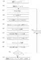
次にステップS8の接触状態判定ルーチンについて図7を用いて説明する。接触判定は複数のチェックを用いて行われる。 Next, the contact state determination routine in step S8 will be described with reference to FIG. The contact determination is performed using a plurality of checks.
まず、ステップ7で測定された生体5に生じた複素電圧VBが正の値であるかをチェックする(ステップS61)。ここでVBが負の値である場合には、明らかに生体が接触していない状態での測定結果が得られていること意味し、この時点で接触が不良であることが解る。First, it is checked whether or not the complex voltage VB generated in the living
更に、ステップS22で得られる内部基準器7のインピーダンス成分で測定された電圧VRRが、予め記憶されている閾値電圧VT1より大きな値であるかをチェックする。この閾値電圧VT1は、ここでは生体の接触が正常時に得られる電圧の1/2の値としておき、このVT1よりもVRRが小さい場合には、接触が不良であると判断される(ステップS62)。Further, it is checked whether or not the voltage VRR measured with the impedance component of the
次にステップS7で演算された、生体5の真のインピーダンスの抵抗成分RBの値が、正常範囲内であるかをチェックする。ここでは200Ω<RB<1000Ωとし、この範囲内に収まらない場合には接触不良であるとする(ステップS63)。Then calculated in step S7, the value of the resistance component RB of the true impedance of the living
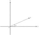
更に、生体5の位相差に関するパラメータが正常範囲内であるかをチェックする。ここでは位相差に関するパラメータとしてX/R(=tanθ)の値を用いる。本発明者が、この値に関して検証するために、実際に複数の被験者における両足間のインピーダンスの測定を行い、R成分とX成分とを演算した。その値をグラフ上にプロットしたものを図8に示す。これをみて解るように、人体の両足間のR成分は約300〜700Ω程度に収まり、またX成分は−20〜−90Ω程度に収まる値である。つまり、生体の両足間のインピーダンスの抵抗成分Rとリアクタンス成分Xは、ある決まった範囲内にあり、仮に測定値がこの正常な領域から外れるような場合には、接触不良であると判断できる。 Further, it is checked whether the parameter relating to the phase difference of the living
従って、ここでは−0.25<X/R<0という条件を決め、この範囲内にあるかどうかで、接触状態を判定する(ステップS64)。 Accordingly, here, a condition of −0.25 <X / R <0 is determined, and the contact state is determined based on whether or not the condition is within this range (step S64).
図8の斜線に示した領域は、ステップS63における200Ω<R<1000Ωのうちの200Ω<Rと、ステップS64における−0.25<X/R<0のうちの−0.25<X/Rとを組み合わせた領域であるが、このような領域にあるということは、明らかに生体が接触していないことを意味しており、本発明の接触状態の判定が有効であることが解るものである。 The hatched area in FIG. 8 indicates 200Ω <R out of 200Ω <R <1000Ω in step S63 and −0.25 <X / R out of −0.25 <X / R <0 in step S64. However, the fact that it is in such a region clearly means that the living body is not in contact, and it is understood that the determination of the contact state of the present invention is effective. is there.
更に今回測定された抵抗成分Rと、前回の生体電気インピーダンス測定ルーチンで測定されたRとを比較することで、安定した値を保持しているかを判定する。ただし接触正常回数iが0の場合には、接触状態の正常状態が初回であるため、この判定は行わない(ステップS65)。接触正常回数iが0以外の場合には、前回の値と比較を行う。ここでは、今回測定された抵抗成分Rが、前回測定された抵抗成分Rと比較して、±3Ω以内であるかを判定する(ステップS66)。ここで±3Ω以内であれば、接触正常と判断し、接触正常回数iを+1する(ステップS67)。 Furthermore, the resistance component R measured this time is compared with R measured in the previous bioelectrical impedance measurement routine to determine whether a stable value is maintained. However, when the normal contact number i is 0, the normal state of the contact state is the first time, so this determination is not performed (step S65). If the normal contact count i is other than 0, the previous value is compared. Here, it is determined whether or not the resistance component R measured this time is within ± 3Ω compared to the resistance component R measured last time (step S66). Here, if within ± 3Ω, it is determined that the contact is normal, and the normal contact number i is incremented by 1 (step S67).
一方、ステップS61、S62、S63、S64、S66で、いずれか一つでも判定結果がNOの場合には、接触状態が不良であるとして、接触正常回数i=0とする(ステップS68)。 On the other hand, if the determination result is NO in any one of steps S61, S62, S63, S64, and S66, it is determined that the contact state is defective and the normal contact count i = 0 (step S68).
以上のように、接触の判定状況により、接触正常回数が決定されることで接触状態判定ルーチンは終了する(ステップS69)。 As described above, the contact state determination routine ends when the number of normal contacts is determined according to the contact determination state (step S69).
以上、本発明の実施例を説明したが、ここでは抵抗成分、リアクタンス成分の算出として、ステップS21〜S32に示す方法を用いたが、多周波数の測定電流による生体電気インピーダンス測定を行い、コールコールの円弧則に従い、各レジスタンス成分、リアクタンス成分を算出することから、本発明の電極の接触状態を判定する技術を適用してもよい。 The embodiment of the present invention has been described above. Here, the method shown in steps S21 to S32 is used for the calculation of the resistance component and the reactance component. Since the resistance component and the reactance component are calculated according to the arc rule, the technique for determining the contact state of the electrode according to the present invention may be applied.
また、ここでは測定される生体電気インピーダンスにおける抵抗成分をR、リアクタンス成分をXとしたとき、X/Rで示される値を用いて、その値の適正範囲により接触状態を判定するものとして説明したが、抵抗成分R及びリアクタンス成分Xのそれぞれの値に適正範囲を設けて、その範囲内にあるかにより電極と生体の接触状態を判定するものとしてもよい。 In addition, here, when the resistance component in the measured bioelectrical impedance is R and the reactance component is X, the contact state is determined based on the appropriate range of the value using the value indicated by X / R. However, an appropriate range may be provided for each value of the resistance component R and the reactance component X, and the contact state between the electrode and the living body may be determined based on whether the value is within the range.
また、ここでは接触状態の判定に使用する位相差に関するパラメータとしてX/Rで示される値を用いて説明したが、|X|/Rまたは|X/R|で示される値を用いても、本発明と同様の効果が得られる。 Further, here, the description is made using the value indicated by X / R as the parameter relating to the phase difference used for the determination of the contact state. However, even if the value indicated by | X | / R or | X / R | The same effect as the present invention can be obtained.
また、この実施例では生体電気インピーダンス測定ルーチンで、真のインピーダンスの抵抗成分とリアクタンス成分とを演算し、その後、接触状態判定ルーチンにおいて、接触状態を判定しているが、真のインピーダンスの演算を行うステップS32の時点で、VBとVRは測定できていればステップS61,62の判定は可能なので、真のインピーダンスの演算S33は、接触状態判定ルーチンの途中(例えばステップS62とS63の間)で行うこととすれば、その時点で接触不良と判定された場合には、真のインピーダンスの演算を省略することができる。In this embodiment, the resistance component and reactance component of the true impedance are calculated in the bioelectrical impedance measurement routine, and then the contact state is determined in the contact state determination routine. However, the true impedance is calculated. at the time of step S32 of performing,V sinceB andV R are possible determination of step S61,62 if measurable, the operation S33 in true impedance between the middle (e.g., steps S62 and S63 in contact state determining routine ), It is possible to omit the calculation of the true impedance when it is determined that the contact is poor at that time.
また、本発明は生体電気インピーダンス値(Z=R+jX)を用いる判定方法として説明したが、アドミッタンス(Y=1/R+1/X=G+jB)として考えると、コンダクタンスGとサセプタンスBを用いてG/BをR/Xの代わりに用いることとしても、本発明と同様に、位相差に関するパラメータを用いていることに変わりなく、接触状態の判定を行うことは可能である。 Further, the present invention has been described as a determination method using the bioelectrical impedance value (Z = R + jX). However, when considered as admittance (Y = 1 /
更に本発明では、X/Rで示される値を位相角に関するパラメータとして説明しているが、一般にtan−12πft=X/Rの関係があることは周知であり、位相差のパラメータとしてtを用いても、本発明と同様の効果が得られる。Furthermore, in the present invention, the value represented by X / R is described as a parameter related to the phase angle. However, it is well known that there is a general relationship of tan−1 2πft = X / R, and t is used as a parameter of the phase difference. Even if it uses, the effect similar to this invention is acquired.
1 測定手段
2 記憶部
3 マイコン
4 表示部
5 生体
6 外部基準器
7 内部基準器
8 定電圧(正弦波交流)発生器
9 電圧/電流変換器
10 電極A
11 電極B
12 切替器
13 増幅器
14 フィルタ
15 A/D変換器
16 分離手段
17 演算式記憶手段
18 変動定数記憶手段
19 変動定数演算手段
20 生体インピーダンス演算手段
21 入力手段DESCRIPTION OF
11 Electrode B
DESCRIPTION OF
Claims (6)
Translated fromJapanese生体の位相差に関するパラメータを用いて前記電極と生体との接触状態を判定する判定手段を備えることを特徴とする生体電気インピーダンス測定装置。In a bioelectrical impedance measuring apparatus comprising an impedance measuring means for measuring bioelectrical impedance including an electrode that contacts a living body,
A bioelectrical impedance measuring apparatus comprising: determination means for determining a contact state between the electrode and the living body using a parameter related to a phase difference of the living body.
a<X/R<b
(但しa,bは実数)
であることを特徴とする請求項2に記載の生体電気インピーダンス測定装置。The condition for contact determination in the determination means is as follows:
a <X / R <b
(Where a and b are real numbers)
The bioelectrical impedance measuring apparatus according to claim 2, wherein
Priority Applications (4)
| Application Number | Priority Date | Filing Date | Title |
|---|---|---|---|
| JP2003313381AJP2005080720A (en) | 2003-09-05 | 2003-09-05 | Bioelectrical impedance measuring device |
| EP04018584AEP1512371B1 (en) | 2003-09-05 | 2004-08-05 | Bioelectrical impedance measuring apparatus |
| DE602004004015TDE602004004015T2 (en) | 2003-09-05 | 2004-08-05 | Device for measuring the bioelectrical impedance |
| US10/916,476US7313435B2 (en) | 2003-09-05 | 2004-08-12 | Bioelectric impedance measuring apparatus |
Applications Claiming Priority (1)
| Application Number | Priority Date | Filing Date | Title |
|---|---|---|---|
| JP2003313381AJP2005080720A (en) | 2003-09-05 | 2003-09-05 | Bioelectrical impedance measuring device |
Publications (2)
| Publication Number | Publication Date |
|---|---|
| JP2005080720Atrue JP2005080720A (en) | 2005-03-31 |
| JP2005080720A5 JP2005080720A5 (en) | 2006-06-22 |
Family
ID=34131884
Family Applications (1)
| Application Number | Title | Priority Date | Filing Date |
|---|---|---|---|
| JP2003313381APendingJP2005080720A (en) | 2003-09-05 | 2003-09-05 | Bioelectrical impedance measuring device |
Country Status (4)
| Country | Link |
|---|---|
| US (1) | US7313435B2 (en) |
| EP (1) | EP1512371B1 (en) |
| JP (1) | JP2005080720A (en) |
| DE (1) | DE602004004015T2 (en) |
Cited By (7)
| Publication number | Priority date | Publication date | Assignee | Title |
|---|---|---|---|---|
| JP2010508935A (en)* | 2006-11-10 | 2010-03-25 | コーニンクレッカ フィリップス エレクトロニクス エヌ ヴィ | ECG electrode contact quality measurement system |
| JP2011072784A (en)* | 2009-10-01 | 2011-04-14 | Seca Ag | Bioelectrical impedance measuring apparatus and method |
| JP2011251158A (en)* | 2009-04-07 | 2011-12-15 | Tanita Corp | Subcutaneous fat thickness measuring instrument |
| JP2012175992A (en)* | 2011-02-25 | 2012-09-13 | Tanita Corp | Body composition meter |
| JP2015507177A (en)* | 2011-12-08 | 2015-03-05 | キンバリー クラーク ワールドワイド インコーポレイテッド | System, controller and method for determining the conductance of an object |
| US9594104B2 (en) | 2014-10-22 | 2017-03-14 | Natus Medical Incorporated | Simultaneous impedance testing method and apparatus |
| CN112770669A (en)* | 2018-09-27 | 2021-05-07 | 伊派迪迈德公司 | Evaluating impedance measurements |
Families Citing this family (82)
| Publication number | Priority date | Publication date | Assignee | Title |
|---|---|---|---|---|
| US7041096B2 (en)* | 2002-10-24 | 2006-05-09 | Synergetics Usa, Inc. | Electrosurgical generator apparatus |
| EP1816956A4 (en)* | 2004-11-24 | 2010-04-07 | Measurement Ltd | Two wire oscillator system for determining body impedance |
| US20110054343A1 (en) | 2005-07-01 | 2011-03-03 | Impedimed Limited | Monitoring system |
| EP2460468A1 (en) | 2005-07-01 | 2012-06-06 | Impedimed Limited | Monitoring system |
| US7283870B2 (en)* | 2005-07-21 | 2007-10-16 | The General Electric Company | Apparatus and method for obtaining cardiac data |
| JP5208749B2 (en) | 2005-10-11 | 2013-06-12 | インペダイムド・リミテッド | Hydration status monitoring |
| ES2296474B1 (en)* | 2005-10-28 | 2009-03-16 | Universitat Politecnica De Catalunya | METHOD AND APPARATUS FOR OBTAINING HEART FREQUENCY FROM THE VARIATIONS OF ELECTRICAL IMPEDANCE MEASURED BETWEEN THE FEET. |
| US9254163B2 (en) | 2005-12-06 | 2016-02-09 | St. Jude Medical, Atrial Fibrillation Division, Inc. | Assessment of electrode coupling for tissue ablation |
| BRPI0621017A2 (en)* | 2005-12-06 | 2011-11-29 | St Jude Medical Atrial Fibrill Div | tissue ablation electrode junction evaluation |
| US8403925B2 (en) | 2006-12-06 | 2013-03-26 | St. Jude Medical, Atrial Fibrillation Division, Inc. | System and method for assessing lesions in tissue |
| US8603084B2 (en) | 2005-12-06 | 2013-12-10 | St. Jude Medical, Atrial Fibrillation Division, Inc. | System and method for assessing the formation of a lesion in tissue |
| US8406866B2 (en) | 2005-12-06 | 2013-03-26 | St. Jude Medical, Atrial Fibrillation Division, Inc. | System and method for assessing coupling between an electrode and tissue |
| US20090177111A1 (en)* | 2006-12-06 | 2009-07-09 | Miller Stephan P | System and method for displaying contact between a catheter and tissue |
| US10362959B2 (en) | 2005-12-06 | 2019-07-30 | St. Jude Medical, Atrial Fibrillation Division, Inc. | System and method for assessing the proximity of an electrode to tissue in a body |
| US8317783B2 (en)* | 2005-12-06 | 2012-11-27 | St. Jude Medical, Atrial Fibrillation Division, Inc. | Assessment of electrode coupling for tissue ablation |
| US9492226B2 (en)* | 2005-12-06 | 2016-11-15 | St. Jude Medical, Atrial Fibrillation Division, Inc. | Graphical user interface for real-time RF lesion depth display |
| US8998890B2 (en)* | 2005-12-06 | 2015-04-07 | St. Jude Medical, Atrial Fibrillation Division, Inc. | Assessment of electrode coupling for tissue ablation |
| WO2008128281A1 (en) | 2007-04-20 | 2008-10-30 | Impedimed Limited | Monitoring system and probe |
| US20080270037A1 (en)* | 2007-04-30 | 2008-10-30 | Masato Nakada | System and method for measuring and displaying health information |
| US7596411B1 (en)* | 2007-06-08 | 2009-09-29 | Pacesetter, Inc. | Apparatus and method for two-component bioelectrical impedance ratio measuring and monitoring |
| US20110046505A1 (en) | 2007-08-09 | 2011-02-24 | Impedimed Limited | Impedance measurement process |
| EP2194858B1 (en) | 2007-09-14 | 2017-11-22 | Corventis, Inc. | Medical device automatic start-up upon contact to patient tissue |
| US8116841B2 (en) | 2007-09-14 | 2012-02-14 | Corventis, Inc. | Adherent device with multiple physiological sensors |
| WO2009036369A1 (en)* | 2007-09-14 | 2009-03-19 | Corventis, Inc. | System and methods for wireless body fluid monitoring |
| WO2009036316A1 (en) | 2007-09-14 | 2009-03-19 | Corventis, Inc. | Energy management, tracking and security for adherent patient monitor |
| US9186089B2 (en) | 2007-09-14 | 2015-11-17 | Medtronic Monitoring, Inc. | Injectable physiological monitoring system |
| WO2009036327A1 (en) | 2007-09-14 | 2009-03-19 | Corventis, Inc. | Adherent device for respiratory monitoring and sleep disordered breathing |
| EP3922171A1 (en) | 2007-09-14 | 2021-12-15 | Medtronic Monitoring, Inc. | Adherent cardiac monitor with advanced sensing capabilities |
| JP5248073B2 (en)* | 2007-09-28 | 2013-07-31 | 株式会社タニタ | Biometric device |
| US8290578B2 (en) | 2007-12-28 | 2012-10-16 | St. Jude Medical, Atrial Fibrillation Division, Inc. | Method and apparatus for complex impedance compensation |
| US9204927B2 (en) | 2009-05-13 | 2015-12-08 | St. Jude Medical, Atrial Fibrillation Division, Inc. | System and method for presenting information representative of lesion formation in tissue during an ablation procedure |
| EP2257216B1 (en) | 2008-03-12 | 2021-04-28 | Medtronic Monitoring, Inc. | Heart failure decompensation prediction based on cardiac rhythm |
| WO2009146214A1 (en) | 2008-04-18 | 2009-12-03 | Corventis, Inc. | Method and apparatus to measure bioelectric impedance of patient tissue |
| US8870780B2 (en) | 2008-10-15 | 2014-10-28 | The Board Of Trustees Of The Leland Stanford Junior University | Systems and methods for monitoring heart function |
| JP5559810B2 (en) | 2008-12-15 | 2014-07-23 | コーヴェンティス,インク. | Patient monitoring system and method |
| JP2010259776A (en)* | 2009-04-07 | 2010-11-18 | Tanita Corp | Subcutaneous fat thickness measurement device |
| EP2305112A1 (en)* | 2009-10-01 | 2011-04-06 | seca ag | Bioimpedance measuring device |
| WO2011050283A2 (en) | 2009-10-22 | 2011-04-28 | Corventis, Inc. | Remote detection and monitoring of functional chronotropic incompetence |
| US9615767B2 (en) | 2009-10-26 | 2017-04-11 | Impedimed Limited | Fluid level indicator determination |
| CA2778770A1 (en) | 2009-11-18 | 2011-05-26 | Chung Shing Fan | Signal distribution for patient-electrode measurements |
| US9451897B2 (en) | 2009-12-14 | 2016-09-27 | Medtronic Monitoring, Inc. | Body adherent patch with electronics for physiologic monitoring |
| US8965498B2 (en) | 2010-04-05 | 2015-02-24 | Corventis, Inc. | Method and apparatus for personalized physiologic parameters |
| US9011346B2 (en) | 2011-01-27 | 2015-04-21 | The Board Of Trustees Of The Leland Stanford Junior University | Systems and methods for monitoring the circulatory system |
| EP2790576A4 (en) | 2011-12-14 | 2015-07-08 | Intersection Medical Inc | Devices, systems and methods for determining the relative spatial change in subsurface resistivities across frequencies in tissue |
| PT106509B (en)* | 2012-08-24 | 2014-10-03 | Inst Superior Tecnico | DEVICE AND METHOD FOR MEASURING TIME OF PROPAGATION OF THE GALVANIC SKIN RESPONSE |
| JP6210265B2 (en)* | 2012-12-05 | 2017-10-11 | パナソニックIpマネジメント株式会社 | Body composition measuring device, body composition measuring method, and correction method for body composition measuring method |
| KR20150081735A (en)* | 2014-01-06 | 2015-07-15 | 삼성전자주식회사 | Method and Apparatus for Measuring Body Fat in Mobile Device |
| US9546898B2 (en) | 2014-06-12 | 2017-01-17 | PhysioWave, Inc. | Fitness testing scale |
| US9568354B2 (en) | 2014-06-12 | 2017-02-14 | PhysioWave, Inc. | Multifunction scale with large-area display |
| US9943241B2 (en) | 2014-06-12 | 2018-04-17 | PhysioWave, Inc. | Impedance measurement devices, systems, and methods |
| US9949662B2 (en) | 2014-06-12 | 2018-04-24 | PhysioWave, Inc. | Device and method having automatic user recognition and obtaining impedance-measurement signals |
| US10130273B2 (en)* | 2014-06-12 | 2018-11-20 | PhysioWave, Inc. | Device and method having automatic user-responsive and user-specific physiological-meter platform |
| US9693696B2 (en) | 2014-08-07 | 2017-07-04 | PhysioWave, Inc. | System with user-physiological data updates |
| US9498137B2 (en) | 2014-08-07 | 2016-11-22 | PhysioWave, Inc. | Multi-function fitness scale with display |
| CN105640553A (en)* | 2014-11-28 | 2016-06-08 | 富泰华工业(深圳)有限公司 | Movable device, system and method for body fat measurement |
| US10945671B2 (en) | 2015-06-23 | 2021-03-16 | PhysioWave, Inc. | Determining physiological parameters using movement detection |
| US10980483B2 (en) | 2015-11-20 | 2021-04-20 | PhysioWave, Inc. | Remote physiologic parameter determination methods and platform apparatuses |
| US10436630B2 (en) | 2015-11-20 | 2019-10-08 | PhysioWave, Inc. | Scale-based user-physiological data hierarchy service apparatuses and methods |
| US10923217B2 (en) | 2015-11-20 | 2021-02-16 | PhysioWave, Inc. | Condition or treatment assessment methods and platform apparatuses |
| US10553306B2 (en) | 2015-11-20 | 2020-02-04 | PhysioWave, Inc. | Scaled-based methods and apparatuses for automatically updating patient profiles |
| US11561126B2 (en) | 2015-11-20 | 2023-01-24 | PhysioWave, Inc. | Scale-based user-physiological heuristic systems |
| US10395055B2 (en) | 2015-11-20 | 2019-08-27 | PhysioWave, Inc. | Scale-based data access control methods and apparatuses |
| US10390772B1 (en) | 2016-05-04 | 2019-08-27 | PhysioWave, Inc. | Scale-based on-demand care system |
| US10215619B1 (en) | 2016-09-06 | 2019-02-26 | PhysioWave, Inc. | Scale-based time synchrony |
| KR102696362B1 (en) | 2017-02-17 | 2024-08-20 | 삼성전자주식회사 | Electronic device and body composition analysing method |
| US10845955B2 (en) | 2017-05-15 | 2020-11-24 | Apple Inc. | Displaying a scrollable list of affordances associated with physical activities |
| CN107432745B (en)* | 2017-06-27 | 2020-11-24 | 芯海科技(深圳)股份有限公司 | Method for judging wrong standing posture in human body impedance measurement |
| US11083392B2 (en) | 2017-07-13 | 2021-08-10 | Samsung Electronics Co., Ltd. | Bio-processor, bio-signal detecting system, and operation method of bio-processor |
| CN108378850A (en)* | 2017-12-27 | 2018-08-10 | 诺仪器(中国)有限公司 | Body complex impedance measuring system and method |
| DK179980B1 (en) | 2018-03-12 | 2019-11-27 | Apple Inc. | User interfaces for health monitoring |
| CN108649924A (en)* | 2018-05-11 | 2018-10-12 | 新华网股份有限公司 | Detection circuit, method and device for human body resistance and computer readable storage medium |
| JP7381046B2 (en)* | 2019-03-28 | 2023-11-15 | 株式会社タニタ | Body composition meter and body composition measurement program |
| US11234077B2 (en) | 2019-06-01 | 2022-01-25 | Apple Inc. | User interfaces for managing audio exposure |
| US11152100B2 (en) | 2019-06-01 | 2021-10-19 | Apple Inc. | Health application user interfaces |
| US12002588B2 (en) | 2019-07-17 | 2024-06-04 | Apple Inc. | Health event logging and coaching user interfaces |
| CN114706505B (en) | 2019-09-09 | 2025-01-28 | 苹果公司 | Research User Interface |
| CN113558598A (en)* | 2020-04-23 | 2021-10-29 | 华为技术有限公司 | Human body composition detection method and apparatus |
| AU2021283914A1 (en) | 2020-06-02 | 2023-01-19 | Apple Inc. | User interfaces for tracking of physical activity events |
| DK181037B1 (en) | 2020-06-02 | 2022-10-10 | Apple Inc | User interfaces for health applications |
| US12232878B1 (en) | 2020-08-01 | 2025-02-25 | Apple Inc. | Atrial fibrillation user interfaces |
| US11698710B2 (en) | 2020-08-31 | 2023-07-11 | Apple Inc. | User interfaces for logging user activities |
| CN117979895A (en)* | 2021-10-18 | 2024-05-03 | 三星电子株式会社 | Electronic device and method for measuring body impedance |
Family Cites Families (18)
| Publication number | Priority date | Publication date | Assignee | Title |
|---|---|---|---|---|
| JP2835656B2 (en) | 1991-05-21 | 1998-12-14 | 株式会社タニタ | Bioimpedance measurement method |
| US5415176A (en)* | 1991-11-29 | 1995-05-16 | Tanita Corporation | Apparatus for measuring body fat |
| IL102300A (en)* | 1992-06-24 | 1996-07-23 | N I Medical Ltd | Non-invasive system for determining of the main cardiorespiratory parameters of the human body |
| US5335667A (en)* | 1992-11-20 | 1994-08-09 | University Of Utah Research Foundation | Method and apparatus for determining body composition using bioelectrical impedance |
| JP3409095B2 (en) | 1994-12-07 | 2003-05-19 | オムロン株式会社 | Impedance measurement device and health management guideline advice device |
| US7166102B2 (en)* | 1996-10-30 | 2007-01-23 | Megadyne Medical Products, Inc. | Self-limiting electrosurgical return electrode |
| JPH10174680A (en) | 1996-12-17 | 1998-06-30 | Omron Corp | Health management index advising apparatus |
| JP2001521420A (en)* | 1997-04-04 | 2001-11-06 | ミネソタ マイニング アンド マニュファクチャリング カンパニー | Method and apparatus for managing the state of contact of a biomedical electrode with patient skin |
| JP3315623B2 (en)* | 1997-06-19 | 2002-08-19 | オリンパス光学工業株式会社 | Return electrode peeling monitor of electrocautery device |
| US6007532A (en)* | 1997-08-29 | 1999-12-28 | 3M Innovative Properties Company | Method and apparatus for detecting loss of contact of biomedical electrodes with patient skin |
| JP4064028B2 (en)* | 2000-01-05 | 2008-03-19 | 株式会社タニタ | Physical fatigue assessment device |
| WO2002100247A2 (en)* | 2001-06-13 | 2002-12-19 | Ckm Diagnostics, Inc. | Non-invasive method and apparatus for tissue detection |
| JP2003052658A (en) | 2001-08-13 | 2003-02-25 | Yamato Scale Co Ltd | Internal fat measuring apparatus |
| JP2003180647A (en) | 2001-12-14 | 2003-07-02 | Yamato Scale Co Ltd | Body fat meter |
| US7050847B2 (en)* | 2002-03-26 | 2006-05-23 | Stig Ollmar | Non-invasive in vivo determination of body fluid parameter |
| US7103407B2 (en)* | 2002-06-28 | 2006-09-05 | Nokia Corporation | Body fat monitoring system and method employing mobile terminal |
| JP4041360B2 (en)* | 2002-07-11 | 2008-01-30 | 株式会社タニタ | Bioimpedance measurement device |
| US20040167423A1 (en)* | 2002-12-20 | 2004-08-26 | Luana Pillon | RXc graph and RXc Z-score graph methods |
- 2003
- 2003-09-05JPJP2003313381Apatent/JP2005080720A/enactivePending
- 2004
- 2004-08-05DEDE602004004015Tpatent/DE602004004015T2/ennot_activeExpired - Lifetime
- 2004-08-05EPEP04018584Apatent/EP1512371B1/ennot_activeExpired - Lifetime
- 2004-08-12USUS10/916,476patent/US7313435B2/ennot_activeExpired - Fee Related
Cited By (9)
| Publication number | Priority date | Publication date | Assignee | Title |
|---|---|---|---|---|
| JP2010508935A (en)* | 2006-11-10 | 2010-03-25 | コーニンクレッカ フィリップス エレクトロニクス エヌ ヴィ | ECG electrode contact quality measurement system |
| JP2011251158A (en)* | 2009-04-07 | 2011-12-15 | Tanita Corp | Subcutaneous fat thickness measuring instrument |
| JP2011072784A (en)* | 2009-10-01 | 2011-04-14 | Seca Ag | Bioelectrical impedance measuring apparatus and method |
| JP2012175992A (en)* | 2011-02-25 | 2012-09-13 | Tanita Corp | Body composition meter |
| JP2015507177A (en)* | 2011-12-08 | 2015-03-05 | キンバリー クラーク ワールドワイド インコーポレイテッド | System, controller and method for determining the conductance of an object |
| US9594104B2 (en) | 2014-10-22 | 2017-03-14 | Natus Medical Incorporated | Simultaneous impedance testing method and apparatus |
| CN112770669A (en)* | 2018-09-27 | 2021-05-07 | 伊派迪迈德公司 | Evaluating impedance measurements |
| JP2022511363A (en)* | 2018-09-27 | 2022-01-31 | インペディメッド・リミテッド | Evaluation of impedance measurement |
| JP7410937B2 (en) | 2018-09-27 | 2024-01-10 | インペディメッド・リミテッド | Evaluation of impedance measurements |
Also Published As
| Publication number | Publication date |
|---|---|
| DE602004004015T2 (en) | 2007-04-19 |
| EP1512371A1 (en) | 2005-03-09 |
| US20050054944A1 (en) | 2005-03-10 |
| DE602004004015D1 (en) | 2007-02-15 |
| US7313435B2 (en) | 2007-12-25 |
| EP1512371B1 (en) | 2007-01-03 |
Similar Documents
| Publication | Publication Date | Title |
|---|---|---|
| JP2005080720A (en) | Bioelectrical impedance measuring device | |
| JP4041360B2 (en) | Bioimpedance measurement device | |
| US6643543B2 (en) | Body water amount condition judging apparatus by multi-frequency bioelectric impedance measurement | |
| US5817031A (en) | Impedance measuring device and a health management device using the same | |
| KR100423675B1 (en) | Bioelectrical impedance measuring method and body composition measuring apparatus | |
| US6459930B1 (en) | Dehydration condition judging apparatus by measuring bioelectric impedance | |
| US20200359931A1 (en) | Body Composition Scale and Body Composition Measurement Program | |
| KR20010024517A (en) | Body fat meter and body weight scales equipped with body fat meter | |
| JP2002112976A5 (en) | ||
| JP2001212098A (en) | Bioelectrical impedance measuring device integrated on one chip | |
| JP4454092B2 (en) | Body fat mass measuring device | |
| US20220211290A1 (en) | Biological data measurement apparatus, biological data measurement method, and non-transitory computer-readable recording medium | |
| US20150042360A1 (en) | Method and Device for Person Identification | |
| JPH10185A (en) | Diagnosing device for failure in body fluid | |
| JP4812735B2 (en) | Body fat scale | |
| JP5610157B2 (en) | measuring device | |
| CN111526787B (en) | Condition evaluation device, condition evaluation method, and storage medium | |
| JP2003180647A (en) | Body fat meter | |
| JP4671467B2 (en) | Impedance measuring device | |
| JP2003093361A (en) | Bioelectrical impedance detector | |
| KR101932132B1 (en) | Apparatus and measuring body fat and method thereof | |
| KR100592828B1 (en) | Body composition analysis method and device | |
| JP4780824B2 (en) | Body fat scale | |
| JP2005192777A (en) | Impedance measuring device | |
| JP5189158B2 (en) | Body fat scale |
Legal Events
| Date | Code | Title | Description |
|---|---|---|---|
| A521 | Request for written amendment filed | Free format text:JAPANESE INTERMEDIATE CODE: A523 Effective date:20060411 | |
| A621 | Written request for application examination | Free format text:JAPANESE INTERMEDIATE CODE: A621 Effective date:20060411 | |
| A131 | Notification of reasons for refusal | Free format text:JAPANESE INTERMEDIATE CODE: A131 Effective date:20090924 | |
| A02 | Decision of refusal | Free format text:JAPANESE INTERMEDIATE CODE: A02 Effective date:20100218 |