JP2005078353A - Electronic device system and power supply method - Google Patents
Electronic device system and power supply methodDownload PDFInfo
- Publication number
- JP2005078353A JP2005078353AJP2003307639AJP2003307639AJP2005078353AJP 2005078353 AJP2005078353 AJP 2005078353AJP 2003307639 AJP2003307639 AJP 2003307639AJP 2003307639 AJP2003307639 AJP 2003307639AJP 2005078353 AJP2005078353 AJP 2005078353A
- Authority
- JP
- Japan
- Prior art keywords
- electronic device
- connector
- battery
- fuel cell
- battery unit
- Prior art date
- Legal status (The legal status is an assumption and is not a legal conclusion. Google has not performed a legal analysis and makes no representation as to the accuracy of the status listed.)
- Withdrawn
Links
Images


Classifications
- H—ELECTRICITY
- H01—ELECTRIC ELEMENTS
- H01M—PROCESSES OR MEANS, e.g. BATTERIES, FOR THE DIRECT CONVERSION OF CHEMICAL ENERGY INTO ELECTRICAL ENERGY
- H01M16/00—Structural combinations of different types of electrochemical generators
- H01M16/003—Structural combinations of different types of electrochemical generators of fuel cells with other electrochemical devices, e.g. capacitors, electrolysers
- H01M16/006—Structural combinations of different types of electrochemical generators of fuel cells with other electrochemical devices, e.g. capacitors, electrolysers of fuel cells with rechargeable batteries
- H—ELECTRICITY
- H01—ELECTRIC ELEMENTS
- H01M—PROCESSES OR MEANS, e.g. BATTERIES, FOR THE DIRECT CONVERSION OF CHEMICAL ENERGY INTO ELECTRICAL ENERGY
- H01M8/00—Fuel cells; Manufacture thereof
- H01M8/04—Auxiliary arrangements, e.g. for control of pressure or for circulation of fluids
- H01M8/04298—Processes for controlling fuel cells or fuel cell systems
- H01M8/04313—Processes for controlling fuel cells or fuel cell systems characterised by the detection or assessment of variables; characterised by the detection or assessment of failure or abnormal function
- H01M8/0438—Pressure; Ambient pressure; Flow
- H01M8/04425—Pressure; Ambient pressure; Flow at auxiliary devices, e.g. reformers, compressors, burners
- H—ELECTRICITY
- H01—ELECTRIC ELEMENTS
- H01M—PROCESSES OR MEANS, e.g. BATTERIES, FOR THE DIRECT CONVERSION OF CHEMICAL ENERGY INTO ELECTRICAL ENERGY
- H01M8/00—Fuel cells; Manufacture thereof
- H01M8/04—Auxiliary arrangements, e.g. for control of pressure or for circulation of fluids
- H01M8/04298—Processes for controlling fuel cells or fuel cell systems
- H01M8/04313—Processes for controlling fuel cells or fuel cell systems characterised by the detection or assessment of variables; characterised by the detection or assessment of failure or abnormal function
- H01M8/04537—Electric variables
- H01M8/04544—Voltage
- H01M8/04567—Voltage of auxiliary devices, e.g. batteries, capacitors
- H—ELECTRICITY
- H01—ELECTRIC ELEMENTS
- H01M—PROCESSES OR MEANS, e.g. BATTERIES, FOR THE DIRECT CONVERSION OF CHEMICAL ENERGY INTO ELECTRICAL ENERGY
- H01M8/00—Fuel cells; Manufacture thereof
- H01M8/04—Auxiliary arrangements, e.g. for control of pressure or for circulation of fluids
- H01M8/04298—Processes for controlling fuel cells or fuel cell systems
- H01M8/04313—Processes for controlling fuel cells or fuel cell systems characterised by the detection or assessment of variables; characterised by the detection or assessment of failure or abnormal function
- H01M8/04537—Electric variables
- H01M8/04574—Current
- H01M8/04597—Current of auxiliary devices, e.g. batteries, capacitors
- H—ELECTRICITY
- H01—ELECTRIC ELEMENTS
- H01M—PROCESSES OR MEANS, e.g. BATTERIES, FOR THE DIRECT CONVERSION OF CHEMICAL ENERGY INTO ELECTRICAL ENERGY
- H01M8/00—Fuel cells; Manufacture thereof
- H01M8/04—Auxiliary arrangements, e.g. for control of pressure or for circulation of fluids
- H01M8/04298—Processes for controlling fuel cells or fuel cell systems
- H01M8/04313—Processes for controlling fuel cells or fuel cell systems characterised by the detection or assessment of variables; characterised by the detection or assessment of failure or abnormal function
- H01M8/04537—Electric variables
- H01M8/04604—Power, energy, capacity or load
- H01M8/04619—Power, energy, capacity or load of fuel cell stacks
- H—ELECTRICITY
- H01—ELECTRIC ELEMENTS
- H01M—PROCESSES OR MEANS, e.g. BATTERIES, FOR THE DIRECT CONVERSION OF CHEMICAL ENERGY INTO ELECTRICAL ENERGY
- H01M8/00—Fuel cells; Manufacture thereof
- H01M8/04—Auxiliary arrangements, e.g. for control of pressure or for circulation of fluids
- H01M8/04298—Processes for controlling fuel cells or fuel cell systems
- H01M8/04313—Processes for controlling fuel cells or fuel cell systems characterised by the detection or assessment of variables; characterised by the detection or assessment of failure or abnormal function
- H01M8/04537—Electric variables
- H01M8/04604—Power, energy, capacity or load
- H01M8/04626—Power, energy, capacity or load of auxiliary devices, e.g. batteries, capacitors
- H—ELECTRICITY
- H01—ELECTRIC ELEMENTS
- H01M—PROCESSES OR MEANS, e.g. BATTERIES, FOR THE DIRECT CONVERSION OF CHEMICAL ENERGY INTO ELECTRICAL ENERGY
- H01M8/00—Fuel cells; Manufacture thereof
- H01M8/04—Auxiliary arrangements, e.g. for control of pressure or for circulation of fluids
- H01M8/04298—Processes for controlling fuel cells or fuel cell systems
- H01M8/04694—Processes for controlling fuel cells or fuel cell systems characterised by variables to be controlled
- H01M8/04858—Electric variables
- H01M8/04925—Power, energy, capacity or load
- H01M8/04947—Power, energy, capacity or load of auxiliary devices, e.g. batteries, capacitors
- H—ELECTRICITY
- H01—ELECTRIC ELEMENTS
- H01M—PROCESSES OR MEANS, e.g. BATTERIES, FOR THE DIRECT CONVERSION OF CHEMICAL ENERGY INTO ELECTRICAL ENERGY
- H01M8/00—Fuel cells; Manufacture thereof
- H01M8/04—Auxiliary arrangements, e.g. for control of pressure or for circulation of fluids
- H01M8/04298—Processes for controlling fuel cells or fuel cell systems
- H01M8/04694—Processes for controlling fuel cells or fuel cell systems characterised by variables to be controlled
- H01M8/04955—Shut-off or shut-down of fuel cells
- H—ELECTRICITY
- H01—ELECTRIC ELEMENTS
- H01M—PROCESSES OR MEANS, e.g. BATTERIES, FOR THE DIRECT CONVERSION OF CHEMICAL ENERGY INTO ELECTRICAL ENERGY
- H01M2250/00—Fuel cells for particular applications; Specific features of fuel cell system
- H01M2250/30—Fuel cells in portable systems, e.g. mobile phone, laptop
- Y—GENERAL TAGGING OF NEW TECHNOLOGICAL DEVELOPMENTS; GENERAL TAGGING OF CROSS-SECTIONAL TECHNOLOGIES SPANNING OVER SEVERAL SECTIONS OF THE IPC; TECHNICAL SUBJECTS COVERED BY FORMER USPC CROSS-REFERENCE ART COLLECTIONS [XRACs] AND DIGESTS
- Y02—TECHNOLOGIES OR APPLICATIONS FOR MITIGATION OR ADAPTATION AGAINST CLIMATE CHANGE
- Y02B—CLIMATE CHANGE MITIGATION TECHNOLOGIES RELATED TO BUILDINGS, e.g. HOUSING, HOUSE APPLIANCES OR RELATED END-USER APPLICATIONS
- Y02B90/00—Enabling technologies or technologies with a potential or indirect contribution to GHG emissions mitigation
- Y02B90/10—Applications of fuel cells in buildings
- Y—GENERAL TAGGING OF NEW TECHNOLOGICAL DEVELOPMENTS; GENERAL TAGGING OF CROSS-SECTIONAL TECHNOLOGIES SPANNING OVER SEVERAL SECTIONS OF THE IPC; TECHNICAL SUBJECTS COVERED BY FORMER USPC CROSS-REFERENCE ART COLLECTIONS [XRACs] AND DIGESTS
- Y02—TECHNOLOGIES OR APPLICATIONS FOR MITIGATION OR ADAPTATION AGAINST CLIMATE CHANGE
- Y02E—REDUCTION OF GREENHOUSE GAS [GHG] EMISSIONS, RELATED TO ENERGY GENERATION, TRANSMISSION OR DISTRIBUTION
- Y02E60/00—Enabling technologies; Technologies with a potential or indirect contribution to GHG emissions mitigation
- Y02E60/10—Energy storage using batteries
- Y—GENERAL TAGGING OF NEW TECHNOLOGICAL DEVELOPMENTS; GENERAL TAGGING OF CROSS-SECTIONAL TECHNOLOGIES SPANNING OVER SEVERAL SECTIONS OF THE IPC; TECHNICAL SUBJECTS COVERED BY FORMER USPC CROSS-REFERENCE ART COLLECTIONS [XRACs] AND DIGESTS
- Y02—TECHNOLOGIES OR APPLICATIONS FOR MITIGATION OR ADAPTATION AGAINST CLIMATE CHANGE
- Y02E—REDUCTION OF GREENHOUSE GAS [GHG] EMISSIONS, RELATED TO ENERGY GENERATION, TRANSMISSION OR DISTRIBUTION
- Y02E60/00—Enabling technologies; Technologies with a potential or indirect contribution to GHG emissions mitigation
- Y02E60/30—Hydrogen technology
- Y02E60/50—Fuel cells
Landscapes
- Life Sciences & Earth Sciences (AREA)
- Engineering & Computer Science (AREA)
- Sustainable Development (AREA)
- Sustainable Energy (AREA)
- Chemical & Material Sciences (AREA)
- Chemical Kinetics & Catalysis (AREA)
- Electrochemistry (AREA)
- General Chemical & Material Sciences (AREA)
- Manufacturing & Machinery (AREA)
- Fuel Cell (AREA)
- Power Sources (AREA)
Abstract
Translated fromJapaneseDescription
Translated fromJapanese本発明は、例えばダイレクト・メタノール方式の燃料電池を電源として動作可能な電子機器システムの動作制御技術に関する。 The present invention relates to an operation control technique for an electronic device system that can operate using, for example, a direct methanol fuel cell as a power source.
近年、例えばPDA(Personal Digital Assistant)などと称される携帯情報端末やデジタルカメラなど、バッテリにより駆動可能な携帯型の電子機器が種々開発され、広く普及している。 In recent years, various portable electronic devices that can be driven by a battery such as a personal digital assistant (PDA) or a digital camera have been developed and widely used.
また、最近、環境問題が大きな注目を集めており、環境に配慮したバッテリ開発も盛んに行われている。そして、この種のバッテリとして、ダイレクト・メタノール型燃料電池(以下、DMFC:Direct Methanol Fuel Cell)が良く知られている。 Recently, environmental problems have attracted a great deal of attention, and environmentally friendly battery development has been actively conducted. A direct methanol fuel cell (hereinafter referred to as DMFC) is well known as this type of battery.
このDMFCは、燃料として与えられるメタノールと酸素を反応させ、その化学反応により電気エネルギーを得るものであり、多孔性金属または炭素からなる2つの電極が電解質をはさんだ構造をもつ。そして、このDMFCは、有害な廃棄物を発生させないため、その実用化が強く求められている。 This DMFC reacts methanol and oxygen given as fuel to obtain electric energy by the chemical reaction, and has a structure in which two electrodes made of porous metal or carbon sandwich an electrolyte. And since this DMFC does not generate harmful waste, its practical use is strongly demanded.
また、DMFCには、送液・送風ポンプなどの補機が備えられている。DMFCの起動時にはこれらの補機を駆動する必要があるため、一般に、DMFCにはリチウム電池などの2次電池が設けられている。例えば、特許文献1には、燃料電池本体の起動初期において、補機へ電力を供給する起動用電池(2次電池)が開示されている。
DMFCには、上述したリチウム電池などの2次電池が設けられるため、燃料電池ユニット全体の規模が大きくなり、回路の構成が複雑になってしまうという問題がある。また、電子機器側には、燃料電池ユニットを接続するための専用コネクタが設けることから、それに応じて回路構成も複雑になってしまうという問題もある。また、全体の回路構成が複雑となるため、安全性の確保が難しいという問題もある。 Since the DMFC is provided with a secondary battery such as the above-described lithium battery, there is a problem that the scale of the entire fuel cell unit increases and the circuit configuration becomes complicated. Further, since a dedicated connector for connecting the fuel cell unit is provided on the electronic device side, there is a problem that the circuit configuration becomes complicated accordingly. In addition, since the entire circuit configuration is complicated, it is difficult to ensure safety.
本発明は上記実情に鑑みてなされたものであり、安全性を確保しつつ回路構成を簡潔にした電子機器システムおよび電力供給方法を提供することを目的とする。 The present invention has been made in view of the above circumstances, and an object thereof is to provide an electronic device system and a power supply method in which a circuit configuration is simplified while ensuring safety.
本発明に係る電子機器システムは、ACアダプタ接続用端子を有する電子機器と、化学反応により発電可能な燃料電池と繰り返し充放電可能な2次電池とを有する電池ユニットとを具備する電子機器システムであって、前記燃料電池ユニットは、前記燃料電池から発生される電力および前記2次電池から発生される電力の少なくとも一方を、前記ACアダプタ接続用端子を通じて前記電子機器に電力を供給する手段を有することを特徴とする。 An electronic device system according to the present invention is an electronic device system including an electronic device having an AC adapter connection terminal, and a battery unit having a fuel cell capable of generating power by a chemical reaction and a rechargeable secondary battery. The fuel cell unit has means for supplying at least one of the power generated from the fuel cell and the power generated from the secondary battery to the electronic device through the AC adapter connection terminal. It is characterized by that.
また、本発明に係る電子機器システムは、外部装置を接続するためのコネクタを有する電子機器と、化学反応により発電可能な燃料電池を有する電池ユニットとを具備する電子機器システムであって、前記電池ユニットは、前記コネクタを介して前記電子機器に接続可能であり、当該電池ユニットの起動時に前記燃料電池の補機を駆動するための電力供給を前記電子機器から前記コネクタ上の第1のピンを通じて受ける手段と、前記燃料電池から発生される電力を前記コネクタ上の第2のピンを通じて前記電子機器へ供給する手段とを有することを特徴とする。 An electronic device system according to the present invention is an electronic device system including an electronic device having a connector for connecting an external device, and a battery unit having a fuel cell capable of generating power through a chemical reaction, the battery The unit is connectable to the electronic device via the connector, and the power supply for driving the fuel cell auxiliary device is activated from the electronic device through the first pin on the connector when the battery unit is activated. Receiving means and means for supplying electric power generated from the fuel cell to the electronic device through a second pin on the connector.
また、本発明に係る電子機器システムは、繰り返し充放電可能なバッテリを接続するためのバッテリコネクタを有する電子機器と、化学反応により発電可能な燃料電池と繰り返し充放電可能な2次電池とを有する電池ユニットとを具備する電子機器システムであって、前記電池ユニットは、前記バッテリコネクタを介して前記電子機器に接続可能であり、前記燃料電池から発生される電力および前記2次電池から発生される電力の少なくとも一方を、前記バッテリコネクタ上の特定のピンを通じて前記電子機器へ供給する手段を有することを特徴とする。 An electronic device system according to the present invention includes an electronic device having a battery connector for connecting a battery that can be repeatedly charged and discharged, a fuel cell that can generate power by a chemical reaction, and a secondary battery that can be repeatedly charged and discharged. An electronic device system including a battery unit, wherein the battery unit is connectable to the electronic device via the battery connector, and is generated from electric power generated from the fuel cell and the secondary battery. It has a means to supply at least one of electric power to the electronic device through a specific pin on the battery connector.
また、本発明に係る電子機器システムは、繰り返し充放電可能なバッテリを接続するためのバッテリコネクタを有する電子機器と、化学反応により発電可能な燃料電池と繰り返し充放電可能な2次電池とを有する電池ユニットとを具備する電子機器システムであって、前記電池ユニットは、前記燃料電池から発生される電力を前記バッテリコネクタ上の第1のピンを通じて前記電子機器へ供給する手段と、前記バッテリコネクタを介して前記電子機器に接続可能であり、前記2次電池において充放電される電力を前記バッテリコネクタ上の第2のピンを通じて前記電子機器との間で送受する手段とを有することを特徴とする。 An electronic device system according to the present invention includes an electronic device having a battery connector for connecting a battery that can be repeatedly charged and discharged, a fuel cell that can generate power by a chemical reaction, and a secondary battery that can be repeatedly charged and discharged. An electronic device system comprising a battery unit, wherein the battery unit includes means for supplying electric power generated from the fuel cell to the electronic device through a first pin on the battery connector, and the battery connector. And means for transmitting / receiving power charged / discharged in the secondary battery to / from the electronic device through a second pin on the battery connector. .
また、本発明に係る電子機器システムは、外部装置を接続するためのコネクタを有する電子機器と、化学反応により発電可能な燃料電池と繰り返し充放電可能な2次電池とを有する電池ユニットとを具備する電子機器システムであって、前記電池ユニットは、前記燃料電池から発生される電力を前記コネクタ上の第1のピンを通じて前記電子機器へ供給する手段と、前記コネクタを介して前記電子機器に接続可能であり、前記2次電池において充放電される電力を前記コネクタ上の第2のピンを通じて前記電子機器との間で送受する手段とを有することを特徴とする。 In addition, an electronic device system according to the present invention includes an electronic device having a connector for connecting an external device, and a battery unit having a fuel cell that can generate power by a chemical reaction and a secondary battery that can be repeatedly charged and discharged. The battery unit is configured to supply power generated from the fuel cell to the electronic device through a first pin on the connector, and to the electronic device via the connector. And means for transmitting / receiving electric power charged / discharged in the secondary battery to / from the electronic device through a second pin on the connector.
電子機器システムにおいて安全性を確保しつつ回路構成を簡潔にすることができる。 The circuit configuration can be simplified while ensuring safety in the electronic device system.
以下、図面を参照して本発明の実施形態を説明する。
図1は、本発明の各実施形態に共通する電子機器システムの外観を示す図である。Hereinafter, embodiments of the present invention will be described with reference to the drawings.
FIG. 1 is a diagram showing an external appearance of an electronic device system common to each embodiment of the present invention.
図1に示すように、この実施形態の電子機器システムは、電子機器1と、この電子機器1に着脱自在な燃料電池ユニット2とで構成される。電子機器1は、例えば、内側面にLCD(Liquid Crystal Display)を配したフタ部がヒンジ機構により開閉自在に本体部に取り付けられたノート型のパーソナルコンピュータであり、燃料電池ユニット2から供給される電力により動作可能である。一方、燃料電池ユニット2は、化学反応により発電可能なDMFCと、繰り返し充放電可能な2次電池とを内蔵している。
なお、燃料電池ユニット2の形状や、サイズ、回路規模は、各実施形態によって異なる。As shown in FIG. 1, the electronic device system of this embodiment includes an
Note that the shape, size, and circuit scale of the
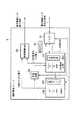
図2は、本発明の各実施形態に共通する燃料電池ユニット2の概略構成を示す図である。
図2に示すように、燃料電池ユニット2は、マイコン21、DMFC22、2次電池23、充電回路24、供給制御回路25、および操作ボタン26を有している。
なお、2次電池23および充電回路24は、実施形態によって、燃料電池ユニット2に搭載される場合と搭載されない場合とがある。FIG. 2 is a diagram showing a schematic configuration of the
As shown in FIG. 2, the
Note that the
マイコン21は、この燃料電池ユニット2全体を動作制御するものであり、電子機器1との間で信号を送受信する通信機能を有する。また、マイコン21は、電子機器1からの指示信号に従ってDMFC22や2次電池23の動作を制御したり、操作ボタン26の操作に応じて対応する処理を実行したりする。 The
DMFC22は、カートリッジ式の燃料タンク221を着脱できるようになっており、この燃料タンク221に格納されたメタノールと空気(酸素)とを化学反応させた際に発電される電力を出力する。この化学反応は、セルスタックなどと称される反応部で行われるが、このセルスタックにメタノールと空気とを効率的に送り込むために、このDMFC22は、ポンプなどの補助機構を備えている。また、このDMFC22は、燃料タンク221の装着有無、燃料タンク221内のメタノールの残量、補助機構の稼働状況および現在の出力電力量をマイコン21に通知する機構を有する。 The DMFC 22 can attach and detach a cartridge-
2次電池23は、DMFC22から出力される電力を充電回路24経由で蓄積し、マイコン21からの指示に応じて、この蓄積した電力を出力する。また、この2次電池23は、その放電特性などを示す基本情報を保持するEEPROM231を備えている。このEEPROM231は、マイコン21からアクセスすることができ、また、2次電池23は、現在の出力電圧値および出力電流値をマイコン21に通知する機構を有する。そして、マイコン21は、EEPROM231から読み出した基本情報と2次電池から通知される出力電圧値および出力電流値とから2次電池23のバッテリ残量を算出し、その値を電子機器1へ通知する。なお、ここでは、この2次電池23は、リチウム電池(LIB)であるものと想定する。 The
充電回路24は、DMFC22から出力される電力を用いて2次電池23を充電するための回路であり、その充電有無はマイコン21によって制御される。 The
供給制御回路25は、DMFC22および2次電池23の電力を状況に応じて外部出力するための回路である。 The
操作ボタン26は、DMFC22もしくは燃料電池ユニット2全体の動作停止などを指示するための専用ボタンである。なお、この操作ボタンと同じ機能を、例えば電子機器1側のLCD画面上でアプリケーションが提示するボタンで実現するようにしてもよいし、電子機器1側の電源ボタンを長押しする(所定時間以上押し続ける)ことで実現するようにしてもよい。 The
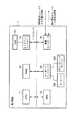
図3は、上記燃料電池ユニット2の別の概略構成を示す図である。なお、図2と共通する要素には同一の符号を付している。
図3に示すように、DMFC22は、燃料タンク221、燃料ポンプ222、混合タンク223、送液ポンプ224、DMFCセルスタッック225および送風ポンプ226から構成される。FIG. 3 is a diagram showing another schematic configuration of the
As shown in FIG. 3, the DMFC 22 includes a
燃料タンク221のメタノールは、燃料ポンプ222により混合タンク223に送り込まれて気化される。そして、この気化されたメタノールは、送液ポンプ224によりDMFCセルスタック225に送り込まれる。また、このDMFCセルスタック225には、送風ポンプ226により空気が送り込まれ、この空気中の酸素と気化されたメタノールとが反応して発電が行われる。 The methanol in the
前述のマイコン21は、電子機器1から送信されてくる起動指示信号に応じて燃料ポンプ222、送液ポンプ224、送風ポンプ226やファンなどの補機を2次電池23の電力により駆動させるための制御を行ったり、DMFCセルスタック225もしくは2次電池23から出力される電力が電子機器1へ供給されるよう供給制御回路25を制御したりする。また、マイコン21は、電子機器1から送信されてくる停止指示信号に応じて、DMFC22の動作を停止させる前に2次電池23の充電を行うための制御を行ったりする。 The above-described
一方、図4は、本発明の各実施形態に共通する電子機器1の概略構成を示す図である。
図4に示すように、電子機器1は、CPU11、RAM(主メモリ)12、HDD13、ディスプレイコントローラ14、キーボードコントローラ15および電源コントローラ16がシステムバスに接続される。On the other hand, FIG. 4 is a figure which shows schematic structure of the
As shown in FIG. 4, in the
CPU11は、この電子機器1全体の動作制御を司るものであり、RAM12に格納された各種プログラムを実行する。RAM12は、この電子機器1の主記憶となるメモリデバイスであり、CPU11によって実行される各種プログラムとこれらのプログラムに用いられる各種データとを格納する。一方、HDD13は、この電子機器1の外部記憶となるメモリデバイスであり、RAM12の補助装置として各種プログラムや各種データを大量に格納する。 The
ディスプレイコントローラ14は、この電子機器1におけるユーザインタフェースのアウトプット側を担うものであり、CPU11が作成した画像データをLCD141に表示制御する。一方、キーボードコントローラ15は、この電子機器1におけるユーザインタフェースのインプット側を担うものであり、キーボード151やポインティングデバイス152の操作を数値化し、内蔵するレジスタを介してCPU11に引き渡す。 The
電源コントローラ16は、この電子機器1内の各部に対する電力供給を制御するものであり、燃料電池ユニット2からの電力供給を受ける受電機能と、燃料電池ユニット2との間で信号を送受信する通信機能とを有する。この電源コントローラ16との間で信号を送受信する燃料電池ユニット2側の相手は、図2及び図3に示したマイコン21である。 The
特に、この燃料電池ユニット2のマイコン21と電子機器1の電源コントローラ16とが有線通信もしくは無線通信を行うことにより、燃料電池ユニット2に内蔵されるDMFC22および2次電池23の状態をステート情報として電子機器1に通知し、これにより、この通知された状態に基づく動作制御を電子機器1で実行するようにしている。 In particular, when the
以下、第1〜第6の実施形態について説明する。
(第1の実施形態)
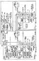
図5は、本発明の第1の実施形態に係る電子機器システムの電力供給に関する構成を示す図である。
この実施形態では、電子機器1本体に設置されている既存のACアダプタ接続用端子(AC電源入力端子)53を利用して、燃料電池ユニット2から電子機器1へ電力を供給する例を示す。Hereinafter, the first to sixth embodiments will be described.
(First embodiment)
FIG. 5 is a diagram illustrating a configuration relating to power supply of the electronic device system according to the first embodiment of the present invention.
In this embodiment, an example in which power is supplied from the
燃料電池ユニット2には、DMFCセルスタック225、2次電池23、充電回路(2次電池用)24のほかに、電源出力端子31、BluetoothTM通信部51、USB通信部52、ACアダプタ接続用端子(AC電源入力端子)53、DC/DC電源回路54、DC/DC電源回路55、マイコン周辺回路56、DMFC用E2PROM57、2次電池用E2PROM58、カートリッジ用E2PROM59、DC/DC電源回路60、補機(ポンプ、ファンなど)61、検出IC63などが設けられる。The
一方、電子機器1には、ACアダプタ接続用端子(AC電源入力端子)32、BluetoothTM通信部71、USB通信部72、充電回路73、DC/DC電源回路74、3端子レギュレータ75などが設けられる。On the other hand, the
燃料電池ユニット2側の電源出力端子31と、電子機器1側のACアダプタ接続用端子32とは、ケーブルなどを介して電気的に接続される。なお、ケーブルなどを用いずに、電源出力端子31とACアダプタ接続用端子32とを直接接続する形態としてもよい。 The
燃料電池ユニット2側において、ACアダプタ接続用端子52から入力される電力は、充電回路24へ送られるようになっている。一方、DMFCセルスタック225から発生される電力は、充電回路24およびDC/DC電源回路54へ送られるようになっている。ACアダプタ接続用端子32からの電力およびDMFCセルスタック225から発生される電力は、ダイオードOR回路を介して選択的に充電回路24へ送られる。充電回路24は、送られてきた電力によって2次電池23を充電する。 On the
検出IC63は、2次電池23における過電圧・過放電を検出し、検出結果に応じて2次電池からの電力の出力を制御するものである。DMFCセルスタック225からの電力および2次電池23からの電力は、ダイオードOR回路を介して選択的にDC/DC電源回路54に送られるようになっている。DC/DC電源回路54は、送られてきた電力から電子機器1の動作に必要な電圧(DC15V)の電力を生成し、これを出力する。DC/DC電源回路54から出力された電力は、電源出力端子31およびACアダプタ接続用端子32を通じて、電子機器1に供給される。 The
また、DMFCセルスタック225からの電力、2次電池23からの電力、およびACアダプタ接続用端子53からの電力は、ダイオードOR回路を通じて選択的に、DC/DC電源回路55およびDC/DC電源回路60へ送られるようになっている。DC/DC電源回路55は、送られてきた電力からマイコン等の動作に必要な電圧の電力を生成し、これをマイコン周辺回路56、DMFC用E2PROM57、2次電池用E2PROM58、カートリッジ用E2PROM59へ供給する。 In addition, the power from the
燃料電池ユニット2内のマイコン(図2および図3のマイコン21に相当)は、BluetoothTM通信部51もしくはUSB通信部52を通じて、燃料電池ユニット2内の各種の情報を電子機器1へ通知する。この場合に通知される情報には、電源の種類が燃料電池である旨、発電能力、DMFCセルスタック225の燃料残量、2次電池23の残量などが含まれる。また、燃料電池ユニット2内のマイコンは、BluetoothTM通信部51もしくはUSB通信部52を通じて、電子機器1からDMFC停止/開始、充電中止/開始などの指示があった場合にはその指示に従う。The microcomputer in the fuel cell unit 2 (corresponding to the
一方、電子機器1側において、ACアダプタ接続用端子32から入力される電力は、充電回路73、DC/DC電源回路74、および3端子レギュレータ75へ送られるようになっている。充電回路73は、送られてきた電力によってメインバッテリを充電する。DC/DC電源回路74は、各種出力電源に必要な電圧を生成して出力する。3端子レギュレータ75は、パワーサプライコントローラや、EC/KBC(Embedded Controller/Keyboard)、I2Cバス等に必要な電圧を生成して出力する。On the other hand, on the
また、燃料電池ユニット2から送信されてくる各種の情報が、BluetoothTM通信部71もしくはUSB通信部72により受信されると、電子機器1内のCPU(図4のCPU11に相当)は、その情報に応じて、当該電子機器1の電源に関する制御(省電力制御など)を行ったり、燃料電池ユニット2の状態を示す画面をLCDに表示したりする。また、その状態を見たユーザからの指示内容、もしくはCPUの判断結果に従い、BluetoothTM通信部71もしくはUSB通信部72を通じて、燃料電池ユニット2にDMFC停止/開始、充電中止/開始などの指示を送る。When various types of information transmitted from the
通常、電子機器1は、ACアダプタ接続用端子に接続されるものがACアダプタであるものと認識した上で動作するため、燃料電池ユニット2は、ACアダプタと同様、常に安定した電力を電子機器1に供給することが望ましい。しかしながら、電源が燃料電池であることから、必ずしも常に安定した電力を電子機器1に供給できるとは限らない。そのために、燃料電池ユニット2と電子機器1との間で連携し、前述した各々のBluetoothTM通信部もしくはUSB通信部を通じて各種情報の交換を行うことにより、システム全体の安全性を保証するものとなっている。Normally, the
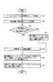
次に、図6のフローチャートを参照して、同実施形態における電力供給に関する動作について説明する。 Next, with reference to the flowchart of FIG. 6, the operation | movement regarding the electric power supply in the same embodiment is demonstrated.
ACアダプタ接続用端子32に、燃料電池ユニット2が電源出力端子31を介して接続され(ステップA1)、電子機器1および燃料電池ユニット2が起動されると(ステップA2)、2次電池およびACアダプタのうちの少なくともいずれかの電力により、補機61が駆動される(ステップA3)。これにより、DMFCセルスタック225が起動される。 When the
また、DMFCセルスタック225、2次電池23、およびACアダプタのうちの少なくともいずれかの電力により、マイコン周辺回路56などが動作することとなる(ステップA4)。そして、DMFCセルスタック225、2次電池23、およびACアダプタのうちの少なくともいずれかの電力が、電源出力端子31およびACアダプタ接続用端子32を通じて、電子機器1へ供給される(ステップA5)。 Further, the microcomputer
また、電子機器1と燃料電池ユニット2との間で、無線通信もしくは有線通信が確立され(ステップA6)、燃料電池ユニット2の電源に関する各種情報(電源の種類が燃料電池である旨、発電能力、DMFCセルスタック225の燃料残量、2次電池23の残量など)を示す情報が電子機器1へ送信される(ステップA7)。 In addition, wireless communication or wired communication is established between the
電子機器1側では、この電源状態を示す情報に応じて、電子機器1内の電源に関する制御(省電力制御など)を行ったり、燃料電池ユニット2の状態を示す画面をLCDに表示したりする(ステップA8)。また、電子機器1は、その状態を見たユーザからの指示内容、もしくはCPUの判断結果に従い、BluetoothTM通信部71もしくはUSB通信部72を通じて、燃料電池ユニット2にDMFC停止/開始、充電中止/開始などの指示を送る処理なども行う。On the
このように、第1の実施形態によれば、電子機器1本体に設置されている既存のACアダプタ接続用端子(AC電源入力端子)を利用して、燃料電池ユニット2から電子機器1へ電力を供給することができる。この場合、既存の電子機器1における大幅な回路変更を伴うことなく、簡潔な構成でシステムを実現できる。また、ACアダプタ接続用端子を介して、ACアダプタと燃料電池ユニット2とを選択的に接続することができるので、ユーザにとっての利便性が向上する。さらに、電子機器1と燃料電池ユニット2との間で通信を介して連携をとることにより、安全性を高めることができる。 Thus, according to the first embodiment, power is supplied from the
なお、電子機器1と燃料電池ユニット2との間で通信を介して連携をとる前述の技術は、以下に紹介する第2〜第6の実施形態に適用してもよい。 It should be noted that the above-described technology for establishing cooperation between the
(第2の実施形態)
図7は、本発明の第2の実施形態に係る電子機器システムの電力供給に関する構成を示す図である。なお、前述の実施形態と同一の構成要素には、同一の符号を付している。
この実施形態では、電子機器1本体に設置されている既存のドッキングコネクタ34を利用して、燃料電池ユニット2から電子機器1へ電力を供給する例を示す。ドッキングコネクタ34は、本来、電子機器1の機能を拡張するために外部装置であるドッカーに接続するためのコネクタである。(Second Embodiment)
FIG. 7 is a diagram showing a configuration relating to power supply of the electronic device system according to the second embodiment of the present invention. In addition, the same code | symbol is attached | subjected to the component same as the above-mentioned embodiment.
In this embodiment, an example is shown in which power is supplied from the
燃料電池ユニット2は、2次電池を搭載しておらず、またこれに関連する充電回路も搭載していない。燃料電池ユニット2の起動時には、電子機器1側からドッキングコネクタ34上の既存のピンを通じて補機を駆動するための電力を供給する構成となっている。また、燃料電池ユニット2側のマイコン等に対しても、電子機器1側からドッキングコネクタ34上の既存のピンを通じて電力を供給できる構成となっている。さらに、ドッキングコネクタ34上に新規に設けたピンを通じて、電子機器1側からDMFC用E2PROM57、カートリッジ用E2PROM59、およびI2Cバスに電力を供給できる構成となっている。また、電子機器1には、メインバッテリ3がメインバッテリ端子33を介して接続されており、燃料電池ユニット2への電力供給はメインバッテリ3を利用して行なわれる。このような構成により、燃料電池ユニット2の構成の簡潔化が図れる。The
また、燃料電池ユニット2内のDC/DC電源回路54は、DMFCセルスタック225から送られてきた電力から電子機器1の動作に必要な電圧の電力を生成し、これを出力する。DC/DC電源回路54から出力された電力は、ドッキングコネクタ34上の既存のピンを通じて、電子機器1に供給される。
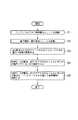
次に、図8のフローチャートを参照して、同実施形態における電力供給に関する動作について説明する。Further, the DC / DC
Next, with reference to the flowchart of FIG. 8, the operation | movement regarding the electric power supply in the embodiment is demonstrated.
ドッキングコネクタ34に、燃料電池ユニット2が接続され(ステップB1)、電子機器1および燃料電池ユニット2が起動されると(ステップB2)、電子機器1からドッキングコネクタ34を通じて供給される電力により、補機61が駆動される(ステップB3)。これにより、DMFCセルスタック225が起動される。 When the
また、電子機器1からドッキングコネクタ34を通じて供給される電力により、マイコン周辺回路56などが動作することとなる(ステップB4)。そして、DMFCセルスタック225から発生される電力が、ドッキングコネクタ34を通じて、電子機器1へ供給される(ステップB5)。 Moreover, the microcomputer
このように、第2の実施形態によれば、電子機器1本体に設置されている既存のドッキングコネクタを利用して、電子機器1からの電力で燃料電池ユニット2側の補機を起動したり、燃料電池ユニット2から電子機器1へ電力を供給したりすることができる。この場合、既存の電子機器1における大幅な回路変更を伴うことなく、簡潔な構成でシステムを実現できる。また、燃料電池ユニット2に2次電池などを搭載していないので、燃料電池ユニット2の構成をより簡潔にすることができる。また、ドッキングコネクタを介して、ドッカーと燃料電池ユニット2とを選択的に接続することができるので、ユーザにとっての利便性が向上する。さらに、電子機器1と燃料電池ユニット2との間で通信を介して連携をとることにより、安全性を高めることができる。 As described above, according to the second embodiment, the auxiliary device on the
(第3の実施形態)
図9は、本発明の第3の実施形態に係る電子機器システムの電力供給に関する構成を示す図である。なお、前述の実施形態と同一の構成要素には、同一の符号を付している。
この実施形態では、前述した第2の実施形態の構成において、起動用乾電池65を燃料電池ユニット2内に追加設置した構成となっている。(Third embodiment)
FIG. 9 is a diagram showing a configuration relating to power supply of an electronic device system according to the third embodiment of the present invention. In addition, the same code | symbol is attached | subjected to the component same as the above-mentioned embodiment.
In this embodiment, in the configuration of the second embodiment described above, a starting
起動用乾電池65は、燃料電池ユニット2の起動用として用いられる乾電池である。例えば燃料電池ユニット2の起動時に、ドッキングコネクタを介して電子機器1側から電力が供給されない場合(もしくは電力が所定値に達しない場合)、補機を起動するために起動用乾電池65からの電力が使用される。また、起動用乾電池65は、マイコン周辺回路56に対しても電力を供給することができる。 The starting
次に、図10のフローチャートを参照して、同実施形態における電力供給に関する動作について説明する。 Next, with reference to the flowchart of FIG. 10, operations related to power supply in the embodiment will be described.
ドッキングコネクタ34に、燃料電池ユニット2が接続され(ステップC1)、電子機器1および燃料電池ユニット2が起動されると(ステップC2)、補機61が駆動されることとなる。ここで、電子機器1からドッキングコネクタ34を通じて電力が供給されれば(ステップC3のYes)、起動用乾電池65が使用されず、電子機器1からの電力により補機61が駆動される(ステップC4)。一方、電子機器1からドッキングコネクタ34を通じて電力が供給されなければ(ステップC3のNo)、起動用乾電池65の電力により補機61が駆動される(ステップC5)。これにより、DMFCセルスタック225が起動される。 When the
また、電子機器1からドッキングコネクタ34を通じて供給される電力、起動用乾電池65、およびDMFCセルスタック225のうちの少なくともいずれかの電力により、マイコン周辺回路56などが動作することとなる(ステップC6)。そして、DMFCセルスタック225から発生される電力が、ドッキングコネクタ34を通じて、電子機器1へ供給される(ステップC7)。 In addition, the microcomputer
このように、第3の実施形態によれば、起動用乾電池65が燃料電池ユニット2内に設けられているため、電子機器1からドッキングコネクタ34を通じて電力が供給されなない場合であっても、起動用乾電池65の電力により補機61を駆動することができ、燃料があってもDMFCセルスタック225を起動できないという事態を避けることができる。 As described above, according to the third embodiment, since the starting
(第4の実施形態)
図11は、本発明の第4の実施形態に係る電子機器システムの電力供給に関する構成を示す図である。なお、前述の実施形態と同一の構成要素には、同一の符号を付している。
この実施形態では、電子機器1本体に設置されている既存のメインバッテリ端子33(図9に示したメインバッテリ端子33と同じ)を利用して、燃料電池ユニット2から電子機器1へ電力を供給する例を示す。メインバッテリ端子33は、本来、電子機器1用のメインバッテリを装着するためのバッテリコネクタである。(Fourth embodiment)
FIG. 11 is a diagram illustrating a configuration related to power supply of an electronic device system according to the fourth embodiment of the present invention. In addition, the same code | symbol is attached | subjected to the component same as the above-mentioned embodiment.
In this embodiment, power is supplied from the
この実施形態では、燃料電池ユニット2内の回路構成は、前述した第1の実施形態における燃料電池ユニット2内の回路構成と類似している(例えば、燃料電池ユニット2内には2次電池23が設けられる)。但し、この実施形態では、DMFCセルスタック225からの電力および2次電池23からの電力は、ダイオードOR回路を介して選択的にメインバッテリ端子33上の既存のピン(1pin)へ送られ、このピンを通じて電子機器1に供給される。この場合、DC/DC電源回路は不要となる。 In this embodiment, the circuit configuration in the
次に、図12のフローチャートを参照して、同実施形態における電力供給に関する動作について説明する。 Next, with reference to the flowchart of FIG. 12, the operation | movement regarding the electric power supply in the same embodiment is demonstrated.
メインバッテリ端子(バッテリコネクタ)33に、燃料電池ユニット2が接続され(ステップD1)、電子機器1および燃料電池ユニット2が起動されると(ステップD2)、2次電池およびACアダプタのうちの少なくともいずれかの電力により、補機61が駆動される(ステップD3)。これにより、DMFCセルスタック225が起動される。 When the
また、DMFCセルスタック225、2次電池23、およびACアダプタのうちの少なくともいずれかの電力により、マイコン周辺回路56などが動作することとなる(ステップD4)。そして、DMFCセルスタック225、2次電池23、およびACアダプタのうちの少なくともいずれかの電力が、メインバッテリ端子33を通じて、電子機器1へ供給される(ステップD5)。 Further, the microcomputer
このように、第4の実施形態によれば、電子機器1本体に設置されている既存のメインバッテリ端子を利用して、燃料電池ユニット2から電子機器1へ電力を供給することができる。この場合、既存の電子機器1における大幅な回路変更を伴うことなく、簡潔な構成でシステムを実現できる。また、メインバッテリ端子を介して、メインバッテリと燃料電池ユニット2とを選択的に接続することができるので、ユーザにとっての利便性が向上する。さらに、電子機器1と燃料電池ユニット2との間で通信を介して連携をとることにより、安全性を高めることができる。 Thus, according to the fourth embodiment, power can be supplied from the
(第5の実施形態)
図13は、本発明の第5の実施形態に係る電子機器システムの電力供給に関する構成を示す図である。なお、前述の実施形態と同一の構成要素には、同一の符号を付している。
この実施形態では、前述の第4の実施形態(図11)と同様、電子機器1本体に設置されている既存のメインバッテリ端子を利用して、燃料電池ユニット2から電子機器1へ電力を供給する例を示す。但し、メインバッテリ端子上に、既存のピンとは別に、電力供給用に新規のピン(11pin, 12pin)が設けられる。このように本実施形態では、既存のメインバッテリ端子を拡張したものであるメインバッテリ端子33Aが使用される。(Fifth embodiment)
FIG. 13: is a figure which shows the structure regarding the electric power supply of the electronic device system which concerns on the 5th Embodiment of this invention. In addition, the same code | symbol is attached | subjected to the component same as the above-mentioned embodiment.
In this embodiment, as in the fourth embodiment (FIG. 11), power is supplied from the
燃料電池ユニット2の起動時には、電子機器1側からメインバッテリ端子33A上に新規に設けたピン(12pin)を通じて補機を駆動するための電力を供給する構成となっている。また、燃料電池ユニット2側のマイコン等に対しても、電子機器1側からメインバッテリ端子33A上の既存のピン(12pin)を通じて電力を供給できる構成となっている。さらに、メインバッテリ端子33A上に新規に設けたピン(4pin)を通じて、電子機器1側からDMFC用E2PROM57、2次電池用E2PROM58、およびカートリッジ用E2PROM59に電力を供給できる構成となっている。 When the
また、燃料電池ユニット2内のDC/DC電源回路54は、DMFCセルスタック225から送られてきた電力から電子機器1の動作に必要な電圧の電力を生成し、これを出力する。DC/DC電源回路54から出力された電力は、メインバッテリ端子33A上に新規に設けたピン(11pin)を通じて、電子機器1に供給される。
また、電子機器1から、メインバッテリ端子33A上の既存のピン(1pin)を通じて、2次電池23に対する充電を行ったり、2次電池23から電子機器1へ電力供給を行ったりする構成となっている。Further, the DC / DC
In addition, the
次に、図14のフローチャートを参照して、同実施形態における電力供給に関する動作について説明する。 Next, with reference to the flowchart of FIG. 14, the operation | movement regarding the electric power supply in the embodiment is demonstrated.
メインバッテリ端子(バッテリコネクタ)33Aに、燃料電池ユニット2が接続され(ステップE1)、電子機器1および燃料電池ユニット2が起動されると(ステップE2)、電子機器1からメインバッテリ端子33Aを通じて供給される電力により、補機61が駆動される(ステップE3)。これにより、DMFCセルスタック225が起動される。 When the
また、DMFCセルスタック225およびACアダプタのうちの少なくともいずれかの電力により、マイコン周辺回路56などが動作することとなる(ステップE4)。そして、DMFCセルスタック225から発生される電力が、メインバッテリ端子33Aを通じて、電子機器1へ供給される(ステップE5)。 Further, the microcomputer
また、電子機器1から、メインバッテリ端子33A上の既存のピン(1pin)を通じて、2次電池23に対する充電を行ったり、2次電池23から電子機器1へ電力供給を行ったりする(ステップE6)。 Further, the
このように、第5の実施形態によれば、電子機器1本体に設置されている既存のメインバッテリ端子に新規ピンを増設したものを利用して、電子機器1からの電力で燃料電池ユニット2側の補機を起動したり、燃料電池ユニット2から電子機器1へ電力を供給したりすることができる。この場合、既存の電子機器1における大幅な回路変更を伴うことなく、簡潔な構成でシステムを実現できる。また、燃料電池ユニット2側の各電力供給源は、独立経路で電子機器1と接続されるため、回路構成を簡潔にすることができる。また、メインバッテリ端子を介して、メインバッテリと燃料電池ユニット2とを選択的に接続することができるので、ユーザにとっての利便性が向上する。さらに、電子機器1と燃料電池ユニット2との間で通信を介して連携をとることにより、安全性を高めることができる。 As described above, according to the fifth embodiment, the
(第6の実施形態)
図15は、本発明の第6の実施形態に係る電子機器システムの電力供給に関する構成を示す図である。なお、前述の実施形態と同一の構成要素には、同一の符号を付している。
この実施形態では、電子機器1本体に設置されている既存のポートリプリケータ用コネクタ(ドッキングコネクタ)34を利用して、燃料電池ユニット2から電子機器1へ電力を供給する例を示す。ポートリプリケータ用コネクタ(ドッキングコネクタ)34は、本来、通信機能などを拡張するためのポートリプリケータを接続するためのコネクタである。(Sixth embodiment)
FIG. 15 is a diagram illustrating a configuration related to power supply of an electronic device system according to the sixth embodiment of the present invention. In addition, the same code | symbol is attached | subjected to the component same as the above-mentioned embodiment.
In this embodiment, an example in which power is supplied from the
この実施形態では、燃料電池ユニット2内の回路構成は、前述した第5の実施形態における燃料電池ユニット2内の回路構成と類似している。また、本実施形態では、ポートリプリケータ用コネクタ(ドッキングコネクタ)34上に、既存のピンとは別に、電力供給用に新規のピン(11pin, 12pin)が設けられる。 In this embodiment, the circuit configuration in the
燃料電池ユニット2の起動時には、電子機器1側からドッキングコネクタ34上に新規に設けたピン(12pin)を通じて補機を駆動するための電力を供給する構成となっている。また、燃料電池ユニット2側のマイコン等に対しても、電子機器1側からドッキングコネクタ34上の既存のピン(12pin)を通じて電力を供給できる構成となっている。さらに、ドッキングコネクタ34上に新規に設けたピン(4pin)を通じて、電子機器1側からDMFC用E2PROM57、2次電池用E2PROM58、およびカートリッジ用E2PROM59に電力を供給できる構成となっている。 When the
また、燃料電池ユニット2内のDC/DC電源回路54は、DMFCセルスタック225から送られてきた電力から電子機器1の動作に必要な電圧の電力を生成し、これを出力する。DC/DC電源回路54から出力された電力は、ドッキングコネクタ34上に新規に設けたピン(11pin)を通じて、電子機器1に供給される。
また、電子機器1から、ドッキングコネクタ34上の既存のピン(1pin)を通じて、2次電池23に対する充電を行ったり、2次電池23から電子機器1へ電力供給を行ったりする構成となっている。Further, the DC / DC
In addition, the
次に、図16のフローチャートを参照して、同実施形態における電力供給に関する動作について説明する。 Next, with reference to the flowchart of FIG. 16, the operation | movement regarding the electric power supply in the same embodiment is demonstrated.
ポートリプリケータ用コネクタであるドッキングコネクタ34に、燃料電池ユニット2が接続され(ステップF1)、電子機器1および燃料電池ユニット2が起動されると(ステップF2)、電子機器1からメインバッテリ端子33Aを通じて供給される電力により、補機61が駆動される(ステップF3)。これにより、DMFCセルスタック225が起動される。 When the
また、DMFCセルスタック225およびACアダプタのうちの少なくともいずれかの電力により、マイコン周辺回路56などが動作することとなる(ステップF4)。そして、DMFCセルスタック225から発生される電力が、ドッキングコネクタ34を通じて、電子機器1へ供給される(ステップF5)。 Further, the microcomputer
また、電子機器1から、ドッキングコネクタ34上の既存のピン(1pin)を通じて、2次電池23に対する充電を行ったり、2次電池23から電子機器1へ電力供給を行ったりする(ステップF6)。 Further, the
このように、第6の実施形態によれば、電子機器1本体に設置されている既存のポートリプリケータ用コネクタ(ドッキングコネクタ)に新規ピンを増設したものを利用して、電子機器1からの電力で燃料電池ユニット2側の補機を起動したり、燃料電池ユニット2から電子機器1へ電力を供給したりすることができる。この場合、既存の電子機器1における大幅な回路変更を伴うことなく、簡潔な構成でシステムを実現できる。また、燃料電池ユニット2側の各電力供給源は、独立経路で電子機器1と接続されるため、回路構成を簡潔にすることができる。また、ポートリプリケータ用コネクタ(ドッキングコネクタ)を介して、ポートリプリケータと燃料電池ユニット2とを選択的に接続することができるので、ユーザにとっての利便性が向上する。さらに、電子機器1と燃料電池ユニット2との間で通信を介して連携をとることにより、安全性を高めることができる。 As described above, according to the sixth embodiment, the power from the
なお、本発明は上記実施形態そのままに限定されるものではなく、実施段階ではその要旨を逸脱しない範囲で構成要素を変形して具体化できる。また、上記実施形態に開示されている複数の構成要素の適宜な組み合わせにより、種々の発明を形成できる。例えば、実施形態に示される全構成要素から幾つかの構成要素を削除してもよい。さらに、異なる実施形態にわたる構成要素を適宜組み合わせてもよい。 Note that the present invention is not limited to the above-described embodiment as it is, and can be embodied by modifying the constituent elements without departing from the scope of the invention in the implementation stage. In addition, various inventions can be formed by appropriately combining a plurality of components disclosed in the embodiment. For example, some components may be deleted from all the components shown in the embodiment. Furthermore, constituent elements over different embodiments may be appropriately combined.
1…電子機器、2…燃料電池ユニット、3…メインバッテリ、21…マイコン、22…DMFC、23…2次電池、24…充電回路、25…供給制御回路、26…操作ボタン、31…電源出力端子、32…ACアダプタ接続用端子(AC電源入力端子)、33…メインバッテリ端子、34…ドッキングコネクタ、51…BluetoothTM通信部、52…USB通信部、53…ACアダプタ接続用端子(AC電源入力端子)、54…DC/DC電源回路、55…DC/DC電源回路、56…マイコン周辺回路、57…DMFC用E2PROM、58…2次電池用E2PROM、59…カートリッジ用E2PROM、60…DC/DC電源回路、61…補機、63…検出IC、65…起動用乾電池、71…BluetoothTM通信部、72…USB通信部、73…充電回路、74…DC/DC電源回路、75…3端子レギュレータ、141…LCD、151…キーボード、152…ポインティングデバイス、221…燃料タンク、222…燃料ポンプ、223…混合タンク、224…送液ポンプ、225…DMFCセルスタック、226…送風ポンプ、231…E2PROM。DESCRIPTION OF
Claims (19)
Translated fromJapanese化学反応により発電可能な燃料電池と繰り返し充放電可能な2次電池とを有する電池ユニットとを具備する電子機器システムであって、
前記燃料電池ユニットは、前記燃料電池から発生される電力および前記2次電池から発生される電力の少なくとも一方を、前記ACアダプタ接続用端子を通じて前記電子機器に電力を供給する手段を有することを特徴とする電子機器システム。An electronic device having an AC adapter connection terminal;
An electronic device system comprising a battery unit having a fuel cell capable of generating electricity by a chemical reaction and a secondary battery capable of being repeatedly charged and discharged,
The fuel cell unit includes means for supplying at least one of electric power generated from the fuel cell and electric power generated from the secondary battery to the electronic device through the AC adapter connection terminal. Electronic equipment system.
前記電子機器は、前記通信手段を通じて前記電池ユニットの電源に関する各種状態を示す情報を取得すると共に、その情報に応じて少なくとも当該電子機器の電源に関する制御を行う手段を有することを特徴とする請求項1記載の電子機器システム。The battery unit and the electronic device each have communication means for communicating with each other,
The electronic device includes means for acquiring information indicating various states relating to the power supply of the battery unit through the communication means, and performing at least control relating to the power supply of the electronic device according to the information. 1. The electronic device system according to 1.
化学反応により発電可能な燃料電池を有する電池ユニットとを具備する電子機器システムであって、
前記電池ユニットは、前記コネクタを介して前記電子機器に接続可能であり、当該電池ユニットの起動時に前記燃料電池の補機を駆動するための電力供給を前記電子機器から前記コネクタ上の第1のピンを通じて受ける手段と、前記燃料電池から発生される電力を前記コネクタ上の第2のピンを通じて前記電子機器へ供給する手段とを有することを特徴とする電子機器システム。An electronic device having a connector for connecting an external device;
An electronic device system comprising a battery unit having a fuel cell capable of generating electricity by a chemical reaction,
The battery unit is connectable to the electronic device via the connector, and a power supply for driving an auxiliary device of the fuel cell is activated from the electronic device on the connector when the battery unit is activated. An electronic device system comprising: means for receiving through a pin; and means for supplying electric power generated from the fuel cell to the electronic device through a second pin on the connector.
化学反応により発電可能な燃料電池と繰り返し充放電可能な2次電池とを有する電池ユニットとを具備する電子機器システムであって、
前記電池ユニットは、前記バッテリコネクタを介して前記電子機器に接続可能であり、前記燃料電池から発生される電力および前記2次電池から発生される電力の少なくとも一方を、前記バッテリコネクタ上の特定のピンを通じて前記電子機器へ供給する手段を有することを特徴とする電子機器システム。An electronic device having a battery connector for connecting a rechargeable battery; and
An electronic device system comprising a battery unit having a fuel cell capable of generating electricity by a chemical reaction and a secondary battery capable of being repeatedly charged and discharged,
The battery unit is connectable to the electronic device via the battery connector, and at least one of electric power generated from the fuel cell and electric power generated from the secondary battery is specified on the battery connector. An electronic device system comprising means for supplying the electronic device through a pin.
化学反応により発電可能な燃料電池と繰り返し充放電可能な2次電池とを有する電池ユニットとを具備する電子機器システムであって、
前記電池ユニットは、前記燃料電池から発生される電力を前記バッテリコネクタ上の第1のピンを通じて前記電子機器へ供給する手段と、前記バッテリコネクタを介して前記電子機器に接続可能であり、前記2次電池において充放電される電力を前記バッテリコネクタ上の第2のピンを通じて前記電子機器との間で送受する手段とを有することを特徴とする電子機器システム。An electronic device having a battery connector for connecting a rechargeable battery; and
An electronic device system comprising a battery unit having a fuel cell capable of generating electricity by a chemical reaction and a secondary battery capable of being repeatedly charged and discharged,
The battery unit is connectable to the electronic device via the battery connector, means for supplying electric power generated from the fuel cell to the electronic device through a first pin on the battery connector, An electronic apparatus system comprising: means for transmitting / receiving electric power charged / discharged in a secondary battery to / from the electronic apparatus through a second pin on the battery connector.
化学反応により発電可能な燃料電池と繰り返し充放電可能な2次電池とを有する電池ユニットとを具備する電子機器システムであって、
前記電池ユニットは、前記燃料電池から発生される電力を前記コネクタ上の第1のピンを通じて前記電子機器へ供給する手段と、前記コネクタを介して前記電子機器に接続可能であり、前記2次電池において充放電される電力を前記コネクタ上の第2のピンを通じて前記電子機器との間で送受する手段とを有することを特徴とする電子機器システム。An electronic device having a connector for connecting an external device;
An electronic device system comprising a battery unit having a fuel cell capable of generating electricity by a chemical reaction and a secondary battery capable of being repeatedly charged and discharged,
The battery unit is connectable to the electronic device via the connector, the means for supplying electric power generated from the fuel cell to the electronic device through a first pin on the connector, and the secondary battery And a means for transmitting / receiving the electric power charged / discharged to / from the electronic device through the second pin on the connector.
前記燃料電池ユニットにおける前記燃料電池から発生される電力および前記2次電池から発生される電力の少なくとも一方を、前記ACアダプタ接続用端子を通じて前記電子機器に供給し、
前記電池ユニットの電源に関する各種状態を示す情報を、通信媒体を通じて前記電子機器へ送信し、
前記通信媒体を通じて送信されてくる前記情報に応じて少なくとも前記電子機器の電源に関する制御を行う、
ことを特徴とする電力供給方法。A power supply method applied to an electronic device system including an electronic device having an AC adapter connection terminal, and a battery unit having a fuel cell capable of generating power by a chemical reaction and a secondary battery capable of repeated charge and discharge. ,
Supplying at least one of electric power generated from the fuel cell and electric power generated from the secondary battery in the fuel cell unit to the electronic device through the AC adapter connection terminal;
Information indicating various states relating to the power supply of the battery unit is transmitted to the electronic device through a communication medium,
Performing at least control related to the power supply of the electronic device according to the information transmitted through the communication medium;
The power supply method characterized by the above-mentioned.
前記電池ユニットを、前記コネクタを介して前記電子機器に接続し、
前記電池ユニットの起動時に、前記電子機器から前記コネクタ上の第1のピンを通じて供給される電力で前記燃料電池の補機を駆動し、
前記燃料電池から発生される電力を前記コネクタ上の第2のピンを通じて前記電子機器へ供給する、
ことを特徴とする電力供給方法。A power supply method applied to an electronic device system comprising an electronic device having a connector for connecting an external device, and a battery unit having a fuel cell capable of generating power by a chemical reaction,
Connecting the battery unit to the electronic device via the connector;
When starting up the battery unit, the auxiliary device of the fuel cell is driven by electric power supplied from the electronic device through the first pin on the connector,
Supplying electric power generated from the fuel cell to the electronic device through a second pin on the connector;
The power supply method characterized by the above-mentioned.
前記電池ユニットを、前記コネクタを介して前記電子機器に接続し、
前記燃料電池から発生される電力および前記2次電池から発生される電力の少なくとも一方を、前記バッテリコネクタ上の特定のピンを通じて前記電子機器へ供給する、
ことを特徴とする電力供給方法。Application to an electronic device system comprising an electronic device having a battery connector for connecting a rechargeable battery and a battery unit having a fuel cell capable of generating power by a chemical reaction and a rechargeable secondary battery A power supply method,
Connecting the battery unit to the electronic device via the connector;
Supplying at least one of the power generated from the fuel cell and the power generated from the secondary battery to the electronic device through a specific pin on the battery connector;
The power supply method characterized by the above-mentioned.
前記電池ユニットを、前記コネクタを介して前記電子機器に接続し、
前記燃料電池から発生される電力を前記バッテリコネクタ上の第1のピンを通じて前記電子機器へ供給し、
前記2次電池において充放電される電力を前記バッテリコネクタ上の第2のピンを通じて前記電子機器との間で送受する、
ことを特徴とする電力供給方法。Application to an electronic device system comprising an electronic device having a battery connector for connecting a rechargeable battery and a battery unit having a fuel cell capable of generating power by a chemical reaction and a rechargeable secondary battery A power supply method,
Connecting the battery unit to the electronic device via the connector;
Supplying power generated from the fuel cell to the electronic device through a first pin on the battery connector;
Transmitting / receiving power charged / discharged in the secondary battery to / from the electronic device through a second pin on the battery connector;
The power supply method characterized by the above-mentioned.
前記電池ユニットを、前記コネクタを介して前記電子機器に接続し、
前記燃料電池から発生される電力を前記コネクタ上の第2のピンを通じて前記電子機器へ供給し、
前記2次電池において充放電される電力を前記コネクタ上の第1のピンを通じて前記電子機器との間で送受する、
ことを特徴とする電力供給方法。
A power supply method applied to an electronic device system comprising an electronic device having a connector for connecting an external device, and a battery unit having a fuel cell capable of generating power by a chemical reaction and a rechargeable secondary battery Because
Connecting the battery unit to the electronic device via the connector;
Supplying electric power generated from the fuel cell to the electronic device through a second pin on the connector;
Transmitting / receiving power charged / discharged in the secondary battery to / from the electronic device through a first pin on the connector;
The power supply method characterized by the above-mentioned.
Priority Applications (3)
| Application Number | Priority Date | Filing Date | Title |
|---|---|---|---|
| JP2003307639AJP2005078353A (en) | 2003-08-29 | 2003-08-29 | Electronic device system and power supply method |
| CNA2004100579788ACN1592027A (en) | 2003-08-29 | 2004-08-27 | Electronic system and power supply method |
| US10/927,639US20050048330A1 (en) | 2003-08-29 | 2004-08-27 | Electronic system and power supply method |
Applications Claiming Priority (1)
| Application Number | Priority Date | Filing Date | Title |
|---|---|---|---|
| JP2003307639AJP2005078353A (en) | 2003-08-29 | 2003-08-29 | Electronic device system and power supply method |
Publications (2)
| Publication Number | Publication Date |
|---|---|
| JP2005078353Atrue JP2005078353A (en) | 2005-03-24 |
| JP2005078353A5 JP2005078353A5 (en) | 2006-10-05 |
Family
ID=34214141
Family Applications (1)
| Application Number | Title | Priority Date | Filing Date |
|---|---|---|---|
| JP2003307639AWithdrawnJP2005078353A (en) | 2003-08-29 | 2003-08-29 | Electronic device system and power supply method |
Country Status (3)
| Country | Link |
|---|---|
| US (1) | US20050048330A1 (en) |
| JP (1) | JP2005078353A (en) |
| CN (1) | CN1592027A (en) |
Families Citing this family (11)
| Publication number | Priority date | Publication date | Assignee | Title |
|---|---|---|---|---|
| US20060170391A1 (en)* | 2005-01-28 | 2006-08-03 | Duhane Lam | Fuel cell charger |
| US20070122661A1 (en)* | 2005-11-29 | 2007-05-31 | Symbol Technologies, Inc. | Methods and apparatus for a hybrid power source |
| ITMI20061438A1 (en)* | 2006-07-24 | 2008-01-25 | Campagnolo Srl | METHOD AND RECHARGING SYSTEM OF A BATTERY POWER UNIT |
| TWI334235B (en)* | 2006-12-20 | 2010-12-01 | Compal Electronics Inc | Device of battery power management having universal serial bus connector |
| US20100040914A1 (en)* | 2006-12-29 | 2010-02-18 | Sitaram Ramaswamy | Fuel-cascaded fuel cell stacks with decoupled power outputs |
| JP5261942B2 (en)* | 2007-02-14 | 2013-08-14 | 株式会社リコー | POWER SUPPLY CIRCUIT FOR POWER SUPPLYING CHARGE CONTROL CIRCUIT, CHARGING DEVICE HAVING THE POWER SOURCE CIRCUIT, AND METHOD FOR POWER SUPPLYING CHARGE CONTROL CIRCUIT |
| KR20090009651A (en)* | 2007-07-20 | 2009-01-23 | 삼성에스디아이 주식회사 | Electronic device capable of bidirectional power transfer through port and its operation method |
| US9160022B2 (en)* | 2011-03-22 | 2015-10-13 | Raytheon Company | Systems and methods providing a wearable power generator |
| US9437850B2 (en)* | 2014-04-30 | 2016-09-06 | Johnson Controls Technology Company | Battery construction for integration of battery management system and method |
| WO2020033341A1 (en) | 2018-08-06 | 2020-02-13 | Techtronic Cordless Gp | Systems and methods for selectively enabling the operation of a device |
| CN109217411B (en)* | 2018-09-03 | 2021-01-08 | Oppo广东移动通信有限公司 | Charging method and device and electronic equipment |
Family Cites Families (4)
| Publication number | Priority date | Publication date | Assignee | Title |
|---|---|---|---|---|
| FR2709873B1 (en)* | 1993-09-06 | 1995-10-20 | Imra Europe Sa | Fuel cell voltage generator. |
| US6231371B1 (en)* | 1999-06-25 | 2001-05-15 | Hewlett-Packard Company | Docking station for multiple devices |
| US20030135773A1 (en)* | 2002-01-15 | 2003-07-17 | Song Zhang | Remote sensing of power supply states |
| JP2003223243A (en)* | 2002-01-29 | 2003-08-08 | Toshiba Corp | Information equipment |
- 2003
- 2003-08-29JPJP2003307639Apatent/JP2005078353A/ennot_activeWithdrawn
- 2004
- 2004-08-27USUS10/927,639patent/US20050048330A1/ennot_activeAbandoned
- 2004-08-27CNCNA2004100579788Apatent/CN1592027A/enactivePending
Also Published As
| Publication number | Publication date |
|---|---|
| US20050048330A1 (en) | 2005-03-03 |
| CN1592027A (en) | 2005-03-09 |
Similar Documents
| Publication | Publication Date | Title |
|---|---|---|
| JP3764426B2 (en) | Electronic device and operation control method | |
| JP2005078353A (en) | Electronic device system and power supply method | |
| JP3713496B2 (en) | Electronic device and power control method for electronic device | |
| CN100367156C (en) | Electronic equipment and its power supply conversion control method and power supply conversion setting method | |
| JP3720024B2 (en) | Electronic device system and operation control method | |
| US7620805B2 (en) | Apparatus for updating program in a fuel cell unit | |
| JP4837015B2 (en) | Information processing apparatus system and charging control method | |
| JP2004265000A (en) | Electronic device and power supply setting method for the device | |
| JP3704123B2 (en) | Electronic equipment and battery unit | |
| JP2004296163A (en) | Electronic equipment system and fuel supply method | |
| CN100426578C (en) | Fuel cell unit, control method of fuel cell unit, and information processing apparatus | |
| JP2005108711A (en) | Battery unit and power supply control method | |
| JP2005108712A (en) | Battery unit and output control method | |
| JP2004296127A (en) | Electronic device, fuel cell unit, and operation control method for electronic device | |
| JP5450231B2 (en) | Keyboard connection device | |
| KR100802799B1 (en) | Fuel cell driving method and system implementing the same | |
| JP4746277B2 (en) | FUEL CELL UNIT, INFORMATION PROCESSING DEVICE, AND METHOD FOR POWER SUPPLYING INFORMATION PROCESSING DEVICE | |
| JP2005235784A (en) | Electronic device system and operation control method | |
| JP2006140071A (en) | Power supply | |
| JP4805551B2 (en) | Information processing apparatus system and power supply method | |
| JP2008005634A (en) | Charging apparatus | |
| JP2005100664A (en) | Power supply terminal structure for electronic equipment |
Legal Events
| Date | Code | Title | Description |
|---|---|---|---|
| A521 | Request for written amendment filed | Free format text:JAPANESE INTERMEDIATE CODE: A523 Effective date:20060822 | |
| A621 | Written request for application examination | Free format text:JAPANESE INTERMEDIATE CODE: A621 Effective date:20060822 | |
| A761 | Written withdrawal of application | Free format text:JAPANESE INTERMEDIATE CODE: A761 Effective date:20070521 |