JP2005075106A - Bicycle hub generator - Google Patents
Bicycle hub generatorDownload PDFInfo
- Publication number
- JP2005075106A JP2005075106AJP2003306907AJP2003306907AJP2005075106AJP 2005075106 AJP2005075106 AJP 2005075106AJP 2003306907 AJP2003306907 AJP 2003306907AJP 2003306907 AJP2003306907 AJP 2003306907AJP 2005075106 AJP2005075106 AJP 2005075106A
- Authority
- JP
- Japan
- Prior art keywords
- wiring
- hub
- bicycle
- shaft
- shaft end
- Prior art date
- Legal status (The legal status is an assumption and is not a legal conclusion. Google has not performed a legal analysis and makes no representation as to the accuracy of the status listed.)
- Pending
Links
Images


Classifications
- B—PERFORMING OPERATIONS; TRANSPORTING
- B62—LAND VEHICLES FOR TRAVELLING OTHERWISE THAN ON RAILS
- B62J—CYCLE SADDLES OR SEATS; AUXILIARY DEVICES OR ACCESSORIES SPECIALLY ADAPTED TO CYCLES AND NOT OTHERWISE PROVIDED FOR, e.g. ARTICLE CARRIERS OR CYCLE PROTECTORS
- B62J6/00—Arrangement of optical signalling or lighting devices on cycles; Mounting or supporting thereof; Circuits therefor
- B62J6/06—Arrangement of lighting dynamos or drives therefor
- B62J6/12—Dynamos arranged in the wheel hub
Landscapes
- Engineering & Computer Science (AREA)
- Mechanical Engineering (AREA)
- Connection Of Motors, Electrical Generators, Mechanical Devices, And The Like (AREA)
- Insulation, Fastening Of Motor, Generator Windings (AREA)
- Windings For Motors And Generators (AREA)
- Motorcycle And Bicycle Frame (AREA)
- Iron Core Of Rotating Electric Machines (AREA)
- Axle Suspensions And Sidecars For Cycles (AREA)
Abstract
Description
Translated fromJapanese本発明は、ハブダイナモ、特に、自転車の車輪中央部に設けられ、自転車に装着される外部機器に電力を供給可能な自転車用ハブダイナモに関する。 The present invention relates to a hub dynamo, and more particularly to a bicycle hub dynamo that is provided at the center of a bicycle wheel and can supply power to an external device attached to the bicycle.
一般に、自転車の車輪の中央部に設けられるハブは、自転車のフレーム(たとえば、フロントフォークやチェーンスティ)に着脱自在かつ回転不能に装着されるハブ軸と、ハブ軸に回転自在に装着されるハブ体と、ハブ体をハブ軸に対して回転自在に支持する軸受とを備えている。また、ハブ体は、車輪のスポークを係止可能な一対のハブフランジが両端外周部に形成されている。 In general, a hub provided at the center of a bicycle wheel includes a hub shaft that is detachably and non-rotatably mounted on a bicycle frame (for example, a front fork or a chain stay), and a hub that is rotatably mounted on the hub shaft. And a bearing that rotatably supports the hub body with respect to the hub shaft. Further, the hub body is formed with a pair of hub flanges that can lock the spokes of the wheels at the outer peripheral portions at both ends.
このように構成された自転車用ハブにおいて、ランプなどの外部機器の電源としての発電機構をハブ体内部に組み込んだハブダイナモが知られている(たとえば特許文献1参照)。従来のハブダイナモでは、発電機構で発電された電力は、配線によりランプなどの外部機器に供給されている。配線は、ハブ軸の外周ではなくハブ軸中心に形成された貫通孔を通って軸端から取り出される。このように、発電機構をハブ体内部に組み込むと、回転部分に対して非接触かつすべりが生じることなく発電するので、車輪のリムに接触するタイプのダイナモより、発電効率が向上しかつ車輪の回転ロスが減少する。
前記従来の構成では、配線がハブ軸内部を通るので、ハブ軸の外周に配線を通す構成に比べてハブ内では配線を保護しやすい。しかし、軸端から取り出された配線が外部に露出するため、配線が保護されず断線するおそれがある。そこで配線をカバーするカバー部材を軸端に設けることが考えられる。しかし、カバー部材を取り付けるためには取付構造が別に必要になりハブダイナモの構造が複雑になる。 In the conventional configuration, since the wiring passes through the inside of the hub shaft, the wiring is easily protected in the hub as compared with the configuration in which the wiring is passed through the outer periphery of the hub shaft. However, since the wiring taken out from the shaft end is exposed to the outside, the wiring may not be protected and may be disconnected. Therefore, it is conceivable to provide a cover member for covering the wiring at the shaft end. However, in order to attach the cover member, a separate attachment structure is required, and the structure of the hub dynamo is complicated.
本発明の課題は、自転車用ハブダイナモにおいて、簡素な構造で軸端から取り出される配線を保護できるようにすることにある。 SUMMARY OF THE INVENTION An object of the present invention is to provide a bicycle hub dynamo that can protect a wiring taken out from a shaft end with a simple structure.
発明1に係る自転車用ハブダイナモは、自転車の車輪中央部に設けられるダイナモであって、ハブ軸と、ハブ体と、発電機構と、配線と、配線通路と、配線取出部とを備えている。ハブ軸は、第1及び第2端部が第1及び第2結合部材により自転車のフレームに装着される軸である。ハブ体は、ハブ軸に回転自在に装着されるものである。発電機構は、ハブ体とハブ軸との間に配置され、両者の相対回転により発電する機構である。配線は、発電機構に接続され外部機器と接続するためのものである。配線通路は、ハブ軸の内部に発電機構から第1軸端に向けて形成され、配線を第1軸端から取出可能なものである。配線取出部は、ハブ軸の第1軸端側に装着される第1結合部材に係合して取り付けられ、配線を外部に案内するものである。 A bicycle hub dynamo according to a first aspect of the present invention is a dynamo provided at the center of a bicycle wheel, and includes a hub shaft, a hub body, a power generation mechanism, wiring, a wiring passage, and a wiring extraction portion. . The hub shaft is a shaft whose first and second end portions are attached to the bicycle frame by the first and second coupling members. The hub body is rotatably mounted on the hub shaft. The power generation mechanism is a mechanism that is disposed between the hub body and the hub shaft and generates power by relative rotation of both. The wiring is connected to the power generation mechanism and connected to an external device. The wiring passage is formed in the hub shaft from the power generation mechanism toward the first shaft end, and the wiring can be taken out from the first shaft end. The wiring take-out portion is attached by engaging with a first coupling member mounted on the first shaft end side of the hub shaft, and guides the wiring to the outside.
このハブダイナモでは、車輪が回転すると発電機構が発電し、発生した電力が配線を介して外部機器に供給される。この配線は、発電機構からハブ軸の内部に形成された配線通路を通って第1軸端に至る。そして、配線取出部により外部に案内される。この配線取出部は、第1軸端にねじ込まれる固定用の第1結合部材に係合して取り付けられている。ここでは、配線通路を通って第1軸端から取り出された配線が配線取出部によって外部に案内されるので配線が保護される。また、配線取出部が第1結合部材に係合して取り付けられているので、特別な取付構造が不要になり、配線取出部の構造が簡素になる。 In this hub dynamo, when the wheel rotates, the power generation mechanism generates power, and the generated power is supplied to the external device via the wiring. This wiring reaches the first shaft end from the power generation mechanism through a wiring passage formed inside the hub shaft. And it is guided outside by the wiring extraction part. The wiring extraction portion is engaged with and attached to a fixing first coupling member that is screwed into the first shaft end. Here, since the wiring taken out from the first shaft end through the wiring passage is guided to the outside by the wiring extraction portion, the wiring is protected. Moreover, since the wiring extraction part is engaged and attached to the first coupling member, a special attachment structure is not required, and the structure of the wiring extraction part is simplified.
発明2に係る自転車用ハブダイナモは、発明1に記載のダイナモにおいて、後方から見てハブ体の右側の第1側面に設けられ、外周に多段ギアを回転不能に装着可能であり、ハブ体に対して自転車の進行方向の回転のみ伝達可能なフリーホイールをさらに備え、第1軸端は後方から見てハブ軸の左側の軸端である。この場合には、リアディレーラなどの外装変速装置に使用される多段ギア側ではなく、その反対側に配線が取り出されるので、配線が錯綜しにくくなる。 A bicycle hub dynamo according to a second aspect of the present invention is the dynamo according to the first aspect, provided on the first side surface on the right side of the hub body when viewed from the rear, and capable of non-rotatably mounting a multistage gear on the outer periphery. A free wheel that can transmit only rotation in the traveling direction of the bicycle is further provided, and the first shaft end is the left shaft end of the hub shaft as viewed from the rear. In this case, since the wiring is taken out not on the multi-stage gear side used in the exterior transmission such as the rear derailleur but on the opposite side, the wiring becomes difficult to be complicated.
発明3に係る自転車用ハブダイナモは、発明2に記載のダイナモにおいて、ハブ体は、発電機構を組み付け可能な開口を第1側面側に有する筒状のケース本体と、開口を覆うようにケース本体に着脱自在に装着された蓋部材とを有し、フリーホイールは蓋部材に装着される。この場合には、フリーホイールを蓋部材とともにケース本体に対して着脱できるので、発電機構のメンテナンスが容易になる。 A bicycle hub dynamo according to a third aspect of the present invention is the dynamo according to the second aspect, wherein the hub body has a cylindrical case main body having an opening on the first side face to which the power generation mechanism can be assembled, and a case main body so as to cover the opening. And a free wheel is attached to the lid member. In this case, since the free wheel can be attached to and detached from the case body together with the lid member, the maintenance of the power generation mechanism is facilitated.
発明4に係る自転車用ハブダイナモは、発明1から3のいずれかに記載のダイナモにおいて、ハブ体の第1側面と逆側の第2側面に設けられ、ハブ体を制動する制動装置を装着するための制動装置装着部をさらに備える。この場合には、リムではなくハブを直接制動するディスクブレーキやローラブレーキ等のハブブレーキをハブ体に装着できるので、比較的高性能な自転車に対しての電装化が容易になる。 A bicycle hub dynamo according to a fourth aspect of the present invention is the dynamo according to any one of the first to third aspects, wherein the bicycle dynamo is provided on a second side opposite to the first side of the hub body, and a braking device for braking the hub body is mounted. A braking device mounting part for further comprising. In this case, a hub brake such as a disc brake or a roller brake that directly brakes the hub, not the rim, can be attached to the hub body, so that it is easy to install a relatively high-performance bicycle.
発明5に係る自転車用ハブダイナモは、発明1から4のいずれかに記載のダイナモにおいて、配線取出部は、第1結合部材に回転不能に装着され、第1軸端から取り出される配線をフレームに沿って取り出せるように第1軸端から折り返して外部に案内する。この場合には、配線取出部から切り出された配線をフレームに容易に沿わすことができる。 A bicycle hub dynamo according to a fifth aspect of the present invention is the dynamo according to any one of the first to fourth aspects, wherein the wiring take-out portion is non-rotatably attached to the first coupling member, and the wiring taken out from the first shaft end is used as a frame. Folded from the end of the first shaft and guided to the outside so that it can be taken out along. In this case, the wiring cut out from the wiring extraction portion can be easily along the frame.
発明6に係る自転車用ハブダイナモは,発明5に記載のダイナモにおいて、配線取出部は、第1結合部材の外周面に回転不能に係合し配線を案内する案内部材と、案内部材に着脱自在に装着され、案内部材をカバーするカバー部材とを有する。この場合には、案内部材がカバー部材によりカバーされるので配線が確実に保護されるとともに、配線取出部を結合部材に確実に固定できる。 The bicycle hub dynamo according to a sixth aspect of the present invention is the dynamo according to the fifth aspect, wherein the wire take-out portion is non-rotatably engaged with the outer peripheral surface of the first coupling member and guides the wiring, and is detachable from the guide member. And a cover member that covers the guide member. In this case, since the guide member is covered by the cover member, the wiring is reliably protected and the wiring extraction portion can be reliably fixed to the coupling member.
発明7に係る自転車用ハブダイナモは、発明5又は6に記載のダイナモにおいて、第1結合部材は六角ナットであり、案内部材は、6以上の回転位相で結合部材の外周面に装着可能である。この場合には、第1結合部材の外周面に多くの回転位相で案内部材を取付できるので、ハブ軸をフレームに固定する際に第1結合部材の回転位相が変化しても配線取出方向の変化が少なくなる。 A bicycle hub dynamo according to a seventh aspect is the dynamo according to the fifth or sixth aspect, wherein the first coupling member is a hexagon nut, and the guide member can be mounted on the outer peripheral surface of the coupling member with a rotational phase of 6 or more. . In this case, since the guide member can be attached to the outer peripheral surface of the first coupling member with many rotational phases, even if the rotational phase of the first coupling member changes when fixing the hub axle to the frame, Less change.
発明8に係る自転車用ハブダイナモは、発明6又は7に記載のダイナモにおいて、案内部材は、配線を第1軸端からハブ軸と実質的に直交する方向に案内する案内空間を有する。この場合には、配線がハブ軸と直交する方向に案内されるので、自転車の転倒時等に配線を保護できる。 A bicycle hub dynamo according to an eighth aspect is the dynamo according to the sixth or seventh aspect, wherein the guide member has a guide space for guiding the wiring from the first shaft end in a direction substantially perpendicular to the hub shaft. In this case, since the wiring is guided in a direction orthogonal to the hub axle, the wiring can be protected when the bicycle falls.
発明9に係る自転車用ハブダイナモは、発明8に記載のダイナモにおいて、案内空間は、配線を収納可能な溝で構成されている。この場合には、案内空間内に配線を収納できる。 A bicycle hub dynamo according to a ninth aspect of the present invention is the dynamo according to the eighth aspect, wherein the guide space is constituted by a groove capable of accommodating a wiring. In this case, the wiring can be stored in the guide space.
発明10に係る自転車用ハブダイナモは、発明6から9のいずれかに記載のダイナモにおいて、案内部材には、カバー部材を第2ねじ部材により取り付けるためのねじ孔が形成されている。この場合には、カバー部材を第2ねじ部材により簡単に着脱できる。 A bicycle hub dynamo according to a tenth aspect of the present invention is the dynamo according to any of the sixth to ninth aspects, wherein the guide member is formed with a screw hole for attaching the cover member with the second screw member. In this case, the cover member can be easily attached and detached by the second screw member.
発明11に係る自転車用ハブダイナモは、発明5から10のいずれかに記載のダイナモにおいて、配線取出部は、第1結合部材の外周面に向けて径方向にねじ込まれる第1ねじ部材により第1ナットに固定されている。この場合には、第1ねじ部材を第1結合部材の外周面に向けてねじ込むだけで配線取出部を簡単に固定できる。 A bicycle hub dynamo according to an eleventh aspect of the present invention is the dynamo according to any one of the fifth to tenth aspects of the present invention, wherein the wiring extraction portion is a first screw member screwed in a radial direction toward the outer peripheral surface of the first coupling member. It is fixed to the nut. In this case, the wiring lead-out portion can be easily fixed simply by screwing the first screw member toward the outer peripheral surface of the first coupling member.
発明12に係る自転車用ハブダイナモは、発明1から4のいずれかに記載のダイナモにおいて、配線取出部は、第1結合部材に回動可能に装着され、ハブ軸の径方向に向けて取り出せるように配線を案内する。この場合には、ハブ軸をフレームに固定する際に第1ナットの回転位相にかかわらず配線の所定の方向に取り出すことができる。 The bicycle hub dynamo according to a twelfth aspect of the present invention is the dynamo according to any one of the first to fourth aspects, wherein the wiring extraction portion is rotatably attached to the first coupling member so as to be taken out in the radial direction of the hub shaft. Guide the wiring. In this case, when fixing the hub axle to the frame, it can be taken out in a predetermined direction of the wiring regardless of the rotational phase of the first nut.
発明13に係る自転車用ハブダイナモは、発明1から12のいずれかに記載のダイナモにおいて、第2結合部材は、第2軸端を覆うように形成された袋ナットである。この場合には、第1軸端が配線取出部でカバーされ、第2軸端が袋ナットにより保護されるので、ハブ軸両端が傷つきにくくなり、ハブ軸の外周に形成されたねじが傷まなくなる。 A bicycle hub dynamo according to a thirteenth aspect of the present invention is the dynamo according to any of the first to twelfth aspects, wherein the second coupling member is a cap nut formed so as to cover the second shaft end. In this case, since the first shaft end is covered by the wiring extraction portion and the second shaft end is protected by the cap nut, both ends of the hub shaft are not easily damaged, and the screw formed on the outer periphery of the hub shaft is not damaged. .
発明14に係る自転車用ハブダイナモは、発明1から13のいずれかに記載のダイナモにおいて、配線取出部は、配線の移動を抑制する配線保持部を有する。この場合には、配線の移動が抑制されるので、配線が外部から引っ張られてもハブ軸内で断線しにくくなる。 A bicycle hub dynamo according to a fourteenth aspect of the present invention is the dynamo according to any one of the first to thirteenth aspects, wherein the wiring extraction portion has a wiring holding portion that suppresses the movement of the wiring. In this case, since the movement of the wiring is suppressed, even if the wiring is pulled from the outside, it is difficult to disconnect in the hub axle.
発明15に係る自転車用ハブダイナモは、発明14に記載のダイナモにおいて、配線取出部は、配線を前記第1軸端から実質的に直交する方向に案内し、配線保持部は、直交部分より外方に配置されている。この場合には、断線しやすい直交部分より外方で配線が保持されるので、配線がより断線しにくくなる。 The bicycle hub dynamo according to a fifteenth aspect is the dynamo according to the fourteenth aspect, wherein the wire take-out portion guides the wire in a direction substantially perpendicular to the first shaft end, and the wire holding portion is located outside the orthogonal portion. It is arranged in the direction. In this case, since the wiring is held outside the orthogonal part where disconnection is likely to occur, the wiring is more difficult to disconnect.
発明16に係る自転車用ハブダイナモは、発明14又は15に記載のダイナモにおいて、配線保持部は、配線を保持するように配置された少なくともひとつの突起部を有する。この場合には、突起部により配線を押圧して配線の弾性を利用して保持できるので、簡単な構成で配線を確実に保持できる。 A bicycle hub dynamo according to a sixteenth aspect of the present invention is the dynamo according to the fourteenth or fifteenth aspect, wherein the wiring holding portion has at least one protrusion arranged to hold the wiring. In this case, the wiring can be held by using the elasticity of the wiring by pressing the wiring with the protrusion, so that the wiring can be reliably held with a simple configuration.
本発明によれば、配線通路を通って第1軸端から取り出された配線が配線取出部によって外部に案内されるので配線が保護される。また、配線取出部が第1結合部材に係合して取り付けられているので、特別な取付構造が不要になり、配線取出部の構造が簡素になる。 According to the present invention, since the wiring taken out from the first shaft end through the wiring passage is guided to the outside by the wiring extraction portion, the wiring is protected. Moreover, since the wiring extraction part is engaged and attached to the first coupling member, a special attachment structure is not required, and the structure of the wiring extraction part is simplified.
図1において、本発明の一実施形態を採用した自転車101は、前部のサスペンションフォーク98及び後部のスイングアーム100を含む前後サスペンションを有するフレーム102と、サスペンションフォーク98に固定されたハンドル104と、チェーンやペダルやディレーラ等からなる駆動部105と、サスペンションフォーク98及びスイングアーム100に装着され、スポーク99を有する前輪及び後輪106,107と、両ディレーラ及び前後のサスペンションを制御する2つの制御装置108,109を備えている。後輪107にはハブダイナモ1(図2)が設けられている。制御装置108は、フレーム102の中央下部のハンガー部の付近に設けられている。制御装置109は表示部を有しており、ハンドル104に装着されている。ハブダイナモ1からの電力は、制御装置108,109及び制御装置108,109を介してディレーラやサスペンションにも供給される。 In FIG. 1, a
図2において、本発明の一実施形態によるハブダイナモ1は、自転車の後輪107に設けられるリアハブであり、ハブ軸5の両端部がフレーム102の後部のスイングアーム100に、ナット50,51により固定され、両ハブフランジ12a,12bにスポーク99が係止されている。 In FIG. 2, the hub dynamo 1 according to the embodiment of the present invention is a rear hub provided on a bicycle
図2に示すハブダイナモ1は、自転車の後輪107とともにスイングアーム100の後端に装着されるものである。このハブダイナモ1は、スイングアーム100の後端部に両端が固定されたハブ軸5と、ハブ軸5の外周側に配置されたハブ体6と、ハブ体6をハブ軸5に対して回転自在に支持するための1対の軸受7,8と、ハブ体6とハブ軸5との間に配置され両者の相対回転により発電する発電機構9と、ハブ体6の図2右側面設けられたフリーホイール10と、ハブ体6の図2左側面に設けられたブレーキ装着部11とを備えている。また、ハブダイナモ1は、発電機構9に接続され制御装置108.109等の外部機器と接続するための配線25と、配線通路26と、配線取出部27とを備えている。配線通路26は、ハブ軸5の内部に発電機構9配置部分から図2左端(第1軸端)に向けて形成され、配線25を左端から取出可能な通路である。配線取出部27は、ハブ軸5の左端側に装着されるナット50に係合して取り付けられ、配線25をカバーして外部に案内するものである。 The hub dynamo 1 shown in FIG. 2 is attached to the rear end of the
ハブ軸5は、たとえばクロムモリブデン鋼製の筒状部材であり、その両端がナット50,51によってスイングアーム100の後端部に固定されている。ナット50は通常の六角ナットであり、ナット51は右軸端を覆うように形成された袋ナットである。ハブ軸5は、発電機構9が装着される部分に大径部5eを有する軸であり、外周面の4箇所に左端から順に雄ねじ部5a〜5dが形成されている。雄ねじ部5aは軸受7の玉押し14b(後述)、玉押し14bを回り止めするためのロックナット14d及びハブ固定用のナット50を装着するためのものである。雄ねじ部5b,5cは大径部5eの両端に形成され発電機構9の内側固定ユニット17(後述)を挟持固定するためのものである。雄ねじ部5dは、軸受8の玉押し15b(後述)、玉押し15bを回り止めするためのロックナット15d及びナット51を装着するためのものである。ハブ軸5の大径部5eの雄ねじ部5b,5c形成部分には、互いに平行な面取り部5f(図4)の形成されている。配線通路26は、ハブ軸5の中心に形成されており、発電機構9の配置部分には、配線通路26に連通する径方向に形成された通過孔26aが形成されている。配線25は、発電機構9から通過孔26aを通って配線通路26に導かれ、配線取出部27から外部に取り出される。この取り出された配線25の先端には、たとえば圧着端子25a(図3)が取り付けられている。 The
ハブ体6は、たとえば軽量なアルミニウム合金製の部材であり、開口12fを図2右側面側に有する筒状のケース本体12と、ケース本体12の開口12fを覆うようにケース本体12に着脱自在に装着された蓋部材13とを有している。ケース本体12の外周面には軸方向に間隔を隔てて配置された1対のハブフランジ12a,12bが形成されている。ケース本体12の開口12fは、発電機構9を組み付け可能な大きさを有しており、そこには、蓋部材13を装着するための雌ねじ部12gが形成されている。ケース本体12の図2左端面にはブレーキ装着部11が設けられている。ケース本体12の左端内周面には、ハブ軸5との隙間をカバーするためのたとえば金属又は合成樹脂製のカバー部材19aが着脱可能に装着されている。1対のハブフランジ12a,12bには、周方向に間隔を隔ててたとえば16個のスポーク係止孔12d,12eがそれぞれ等間隔で形成されている。スポーク係止孔12dとスポーク係止孔12eとは、ピッチが半ピッチ分ずれて形成されている。また、ケース本体12の図2左端面には、内周面にブレーキ装着部11を回り止めするためのセレーションが形成された取付凹部12hが形成されていると共に、内周面にブレーキ装着部11が圧入される圧入孔12iが形成されている。 The
蓋部材13は、ケース本体12の雌ねじ部12gに螺合する雄ねじ部13dを外周に有する外筒部13aと、外筒部13aの内周側に間隔を隔てて配置された内筒部13bと、両筒部13a,13bを連結する連結部13cとが一体形成された部材である。内筒部13bの内周面には、フリーホイール10を連結するための連結ボルト44が螺合している。 The
軸受7は、ケース本体12とハブ軸5との間に装着されている。軸受7は、ブレーキ装着部11の左端内周面に設けられた玉受け14aと、ハブ軸5の雄ねじ部5aに螺合する玉押し14bと、玉押し14bと玉受け14aとの間に両者にそれぞれ接触して転動するボール14cとを有している。軸受8は、フリーホイール10とハブ軸5との間に配置されている。軸受8は、フリーホイール10に設けられた玉受け15aと、ハブ軸5の雄ねじ部5cに螺合する玉押し15bと、玉押し15bと玉受け15aとの間に両者にそれぞれ接触して転動するボール15bとを有している。ボール14c,15cの周囲にはグリースが充填されている。 The bearing 7 is mounted between the
発電機構9は、ケース本体12に固定された永久磁石16と、ハブ軸5に固定された内側固定ユニット17とを有するクローポール構造の発電機構である。 The power generation mechanism 9 is a power generation mechanism having a claw pole structure having a
永久磁石16は、ケース本体12の内面に固定されており、円周方向に等間隔に分割された4個の磁石体から構成されている。この永久磁石16には、等間隔で交互にN極とS極とが着磁されており、それぞれが後述するヨーク外周部と対抗している。 The
内側固定ユニット17は、リング状のコイル20と、コイル20の周囲を囲むように設けられたヨーク21とを有している。そして、これらのコイル20及びヨーク21は、ハブ軸5の外周に形成された雄ねじ部5a,5bに螺合する1対のナット22a,22bにより挟まれるようにしてハブ軸5に固定され、かつ軸方向において永久磁石16に対向するような位置関係に位置決めされている。 The
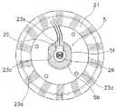
なお、図2に示すように、コイル20及びヨーク21を固定するためのナット22a,22bのヨーク21側には、ワッシャ23a,23bが装着されている。このうち、ワッシャ23aは、図4に示すように、ハブ軸5の面取り部5fに係合する互いに平行な面を有する略長円形の係止孔23cを有しており、ハブ軸5に回転不能に係止される。また、ワッシャ23aには、ヨーク21に係止される突起部23dがヨーク21に向けてプレス加工により突出して形成されている。さらに、ワッシャ23aには、コイル20から導出される配線25を通すためのスリット23eが、配線通路26の通過孔26aに対向する位置から径方向外方に切り欠いて形成されている。 As shown in FIG. 2,
これによりワッシャ23aは、内側固定ユニット17をハブ軸5に対して回り止めできるので、コイル20から取り出された配線25を配線通路26に確実に案内できる。この配線25は、配線通路26を通ってハブ軸5の左端面外部に引き出され、ハブ軸5に設けられた配線取付部27によって案内される。 As a result, the
フリーホイール10は、図2に示すように、ハブ体6の蓋部材13の内周側側面に回転不能に連結されたベース部41と、ベース部41に回転自在に装着されたギア取付部42と、ベース部41とギア取付部42との間に配置されたワンウェイクラッチ43とを有している。 As shown in FIG. 2, the
前述したようにベース部41は、内筒部13bの内周面にねじ込まれた筒状の連結ボルト44により内筒部13bと連結されている。連結ボルト44は頭部でベース部41を係止している。また、内筒部13bとベース部41とは連結ボルト44の外周側で両者の間に配置された連結部材45により回転不能に連結されている。連結部材45の外周面にはセレーションが形成されており、連結部材45は内筒部13bに形成されたセレーションに圧入されている。この圧入された連結部材45のセレーションがベース部41の一端内周面に形成されたセレーションに噛み合っている。これにより、内筒部13bとベース部41とが回転不能に強固に連結されている。 As described above, the
ベース部41は筒状の部材であり、そこには、軸受8の玉受け15aがねじ込まれている。玉受け15aはギア取付部42を支持するための軸受の玉押しと兼用されている。 The
また、ベース部41には、ワンウェイクラッチ43を構成する爪部材43aが起伏自在に装着されている。ワンウェイクラッチ43はギア取付部42に装着された多段ギア54(すなわちペダル)の進行方向の回転のみベース部41に伝達するとともに、後輪107の進行方向の回転を多段ギア54に伝達しないようにするためのクラッチである。爪部材43aはバネ部材43bにより起きる方向に付勢されている。爪部材43aは、ギア取付部42が進行方向に回転すると、ギア取付部42の内周面に形成されたラチェット歯43cに噛み合ってギア取付部42からベース部41に回転を伝達する。 Further, a
ギア取付部42は筒状の部材であり、外周に多段ギア54が着脱自在かつ回転不能に装着される。ギア取付部42の右端内周面には、ハブ軸5との隙間をカバーするためのたとえば金属又は合成樹脂製のカバー部材19b,19cが着脱可能に装着されている。 The
ブレーキ装着部11は、ケース本体12と別体でありケース本体12に圧入固定されていると共に、ローラブレーキ55のブレーキドラム55aが芯出しして装着されるようになっている。ブレーキ装着部11は、大小2段の外周面11a,11bを有する段付き筒状部材である。ブレーキ装着部11は、軸受7の玉受け14aと兼用されており、軸受7として機能するために、ケース本体12の圧入孔12iに小径外周面11bがガタ付きなく圧入固定されている。また、取付凹部12hに噛み合うセレーション11cが大径外周面11aに形成されるとともに、ブレーキドラム55aが回転不能に係止されるセレーション11dが左端に形成されている。 The
配線取出部27は、図2、図3及び図5から図8に示すように、ナット50に回転不能に係合し配線25を案内する案内部材28と、案内部材28をカバーするカバー部材29とを有している。案内部材28は、図5及び図6に示すように、ナット50に回転不能に係止される係止部28aと、ハブ軸5の左端部から取り出された配線25が案内される案内部28bと、係止部28aをナット50に固定ボルト30により固定する固定部28cとを有している。係止部28aは、たとえば、120度の角度の18個の山形部28dを有しており、18の回転位相でナット50の外周面に装着可能である。これにより、ナット50の回転位相が変化しても案内部28bの回転位置を一定方向に近づけることができる。 As shown in FIGS. 2, 3, and 5 to 8, the wire take-out
案内部28bは、少なくとも一部が配線25よりやや小さい幅に形成された溝部28eと、溝部28eに形成され配線25を保持する配線保持部25fとを有しており、配線25を弾性的に係止可能である。溝部28eは、図2に示すように、配線25をハブ軸5の端部から90度折り曲げさらに湾曲させ、全体として配線25を軸端からUターンさせ、スイングアーム100近傍で取り出せるように形成されている。溝部28eは、配線25を外部に突出することなく収納可能な深さを有している。そして外部に取り出された配線25はスイングアーム100に沿って配設される。配線保持部28fは、配線25が軸端から90度折れ曲がった部分より外方で溝部28eの対向する壁部に食い違うように2つずつ形成されている(図7)。このような位置に配線保持部28fを形成すると、配線25がそれぞれの配線保持部28fで交互に異なる方向に押圧され波状に溝部28eを通過する。このため、配線25の移動がその部分で抑制され、配線が外部から引っ張られても配線保持部28fより発電機構9側のハブ軸5内の配線通路26で切断しにくくなる。また、案内部材28には、カバー部材29を固定するためのねじ孔28gがカバー部材29と対向する面に形成されている。 The
固定部28cは、固定ボルト30がねじ込まれるねじ部を有しており、固定ボルト30でナット50の外周面を押圧して案内部材28をナット50に固定している。特に、この実施形態では、スイングアーム100の裏側に配線を配設できるので、配線が自転車の外観に表れにくくなる。 The fixing
カバー部材29は、ねじ孔28gにねじ込まれるビス31により案内部材28に固定されている。カバー部材29は、図2、図5及び図8に示すように、案内部材28のスイングアーム100に対向する面を除く外側面を全面的に覆う形状に形成されている。これにより配線25が保護されるとともに、ハブ軸5の左端部からの異物の浸入を抑えることもできる。 The
次に、ハブダイナモ1の動作について説明する。 Next, the operation of the hub dynamo 1 will be described.
自転車のペダルをこぐとギアクランクの回転がチェーンを介して多段ギア54に伝達され、ギア取付部42が回転する。この回転がワンウェイクラッチ43を介してベース部41に伝達されハブ体6が回転し、後輪107が進行方向に回転する。走行中にペダルをこぐのを止めるとワンウェイクラッチ43がオフして後輪107が回転してもその回転がギア取付部42に伝達されず、ギアクランクは回転しない。しかし、ハブ軸5とハブ体6とが相対回転する。 When the bicycle pedal is stepped on, the rotation of the gear crank is transmitted to the
ハブ軸5に対して後輪107すなわちハブ体6が回転すると、ハブ軸5に固定されている内側固定ユニット17に対して永久磁石16が回転する。これにより、コイル20及びヨーク21の外周側を永久磁石16が回転して発電することになる。 When the
発電された電力は、配線取出部27から外部に導出され、圧着端子25aに接続された配線(図示せず)を介してたとえば、制御装置108,109や前後のディレーラやサスペンションなどの電装品に供給される。ここでは、ハブダイナモ1は後輪107に設けられているので、ランプ以外の後輪からの距離が短い電装品に対して電力の供給を短い距離で行え、電力を効率良く供給できる。また、ハブ軸5の左端から配線25を取り出しているので、リアディレーラへの配線やケーブルと配線25が錯綜することもない。さらに、配線通路26を通って左端から取り出された配線25が配線取出部27にカバーされつつ外部に案内されるので配線25が保護される。また、配線取出部27がナット50に係合して取り付けられているので、特別な取付構造が不要になり、配線取出部27の構造が簡素になる。 The generated electric power is led out to the outside from the
〔他の実施形態〕
(a)前記実施形態では、ナット50に回転不能に配線取出部27を装着したが、図9に示すように、ナット150に回動可能に配線取出部127を装着してもよい。ナット150は、ハブ軸5の雄ねじ部5aに螺合するナット本体150aと、ナット本体150aの左端面に一体形成された回転係止部150bとを有している。配線取出部127は、回転係止部150bに弾性的に係止されて回動可能に装着される案内部材128と、案内部材128をカバーするカバー部材129とを有している。案内部材128は、配線25をハブ軸5の径方向に案内するための案内溝128aを外周部に有している。このような構成では、ハブ軸5をスイングアーム100に固定する際にナット150の回転位相にかかわらず配線25の所定の方向に取り出すことができ、どのような形状のフレームにも配線25を沿わせることができる。[Other Embodiments]
(A) In the above-described embodiment, the
(b)前記実施形態では、後輪に設けられるハブダイナモを例に本発明を説明したが、前輪に設けられるハブダイナモにも本発明を適用できる。 (B) In the above embodiment, the present invention has been described by taking the hub dynamo provided on the rear wheel as an example, but the present invention can also be applied to the hub dynamo provided on the front wheel.
(c)前記実施形態では、配線取出部をハブ軸の後方から見て左側の端部に設けたが、右側の端部に設けてもよい。 (C) In the above embodiment, the wiring extraction portion is provided at the left end portion as viewed from the rear of the hub axle, but may be provided at the right end portion.
1 ハブダイナモ
5 ハブ軸
6 ハブ体
9 発電機構
10 フリーホイール
11 ブレーキ装着部
25 配線
26 配線通路
27,127 配線取出部
28,128 案内部材
28a 係止部
28b 案内部
28c 固定部
28d 山形部
28e 溝部
28f 配線保持部
28g ねじ孔
29,129カバー部材
50,150 ナット
51 ナット
100 スイングアームDESCRIPTION OF SYMBOLS 1
Claims (16)
Translated fromJapanese第1及び第2端部が第1及び第2結合部材により前記自転車のフレームに装着されるハブ軸と、
前記ハブ軸に回転自在に装着されるハブ体と、
前記ハブ体と前記ハブ軸との間に配置され、両者の相対回転により発電する発電機構と、
前記発電機構に接続され外部機器と接続するための配線と、
前記ハブ軸の内部に前記発電機構から第1軸端に向けて形成され、前記配線を前記第1軸端から取出可能な配線通路と、
前記ハブ軸の前記第1軸端側に装着される前記第1結合部材に係合して取り付けられ、前記配線を外部に案内する配線取出部と、
を備えた自転車用ハブダイナモ。A bicycle hub dynamo provided at the center of the bicycle wheel,
A hub axle having first and second ends attached to the frame of the bicycle by first and second coupling members;
A hub body rotatably mounted on the hub shaft;
A power generation mechanism that is disposed between the hub body and the hub shaft, and generates power by relative rotation of both;
Wiring connected to the power generation mechanism and connected to an external device;
A wiring passage formed in the hub shaft from the power generation mechanism toward the first shaft end, and capable of taking out the wiring from the first shaft end;
A wire take-out portion that engages and is attached to the first coupling member mounted on the first shaft end side of the hub shaft and guides the wire to the outside;
Bicycle hub dynamo equipped with.
前記第1軸端は後方から見て前記ハブ軸の左側の軸端である、請求項1に記載の自転車用ハブダイナモ。A free wheel provided on the first side surface on the right side of the hub body as viewed from the rear, and capable of non-rotatably mounting a multistage gear on the outer periphery, and capable of transmitting only rotation in the traveling direction of the bicycle to the hub body In addition,
The bicycle hub dynamo according to claim 1, wherein the first shaft end is a left shaft end of the hub shaft as viewed from the rear.
前記フリーホイールは前記蓋部材に装着される、請求項2に記載の自転車用ハブダイナモ。The hub body includes a cylindrical case main body having an opening on the first side surface to which the power generation mechanism can be assembled, and a lid member detachably attached to the case main body so as to cover the opening. ,
The bicycle hub dynamo according to claim 2, wherein the free wheel is attached to the lid member.
前記第1結合部材に回転不能に係合し前記配線を案内する案内部材と、
前記案内部材に着脱自在に装着され、前記案内部材をカバーするカバー部材とを有する、請求項5に記載の自転車用ハブダイナモ。The wiring extraction part is
A guide member that non-rotatably engages the first coupling member and guides the wiring;
The bicycle hub dynamo according to claim 5, further comprising a cover member that is detachably attached to the guide member and covers the guide member.
前記案内部材は、6以上の回転位相で前記第1結合部材の外周面に装着可能である、請求項5又は6に記載の自転車用ハブダイナモ。The first coupling member is a hexagonal nut;
The bicycle hub dynamo according to claim 5 or 6, wherein the guide member can be mounted on an outer peripheral surface of the first coupling member with a rotational phase of 6 or more.
前記配線保持部は、前記直交部分より外方に配置されている、請求項14に記載の自転車用ハブダイナモ。The wiring extraction portion guides the wiring in a direction substantially orthogonal from the first shaft end,
The bicycle hub dynamo according to claim 14, wherein the wiring holding portion is disposed outward from the orthogonal portion.
Priority Applications (7)
| Application Number | Priority Date | Filing Date | Title |
|---|---|---|---|
| JP2003306907AJP2005075106A (en) | 2003-08-29 | 2003-08-29 | Bicycle hub generator |
| TW093104620ATWI239309B (en) | 2003-08-29 | 2004-02-24 | Bicycle hub generator |
| US10/883,991US6924569B2 (en) | 2003-08-29 | 2004-07-06 | Bicycle hub generator |
| EP04020398AEP1510448B1 (en) | 2003-08-29 | 2004-08-27 | Bicycle hub generator |
| CNA2004100682562ACN1590201A (en) | 2003-08-29 | 2004-08-27 | Bicycle hub generator |
| AT04020398TATE327937T1 (en) | 2003-08-29 | 2004-08-27 | HUB ALTERNATOR FOR BICYCLE |
| DE602004001028TDE602004001028D1 (en) | 2003-08-29 | 2004-08-27 | Hub dynamo for bicycle |
Applications Claiming Priority (1)
| Application Number | Priority Date | Filing Date | Title |
|---|---|---|---|
| JP2003306907AJP2005075106A (en) | 2003-08-29 | 2003-08-29 | Bicycle hub generator |
Publications (1)
| Publication Number | Publication Date |
|---|---|
| JP2005075106Atrue JP2005075106A (en) | 2005-03-24 |
Family
ID=34101248
Family Applications (1)
| Application Number | Title | Priority Date | Filing Date |
|---|---|---|---|
| JP2003306907APendingJP2005075106A (en) | 2003-08-29 | 2003-08-29 | Bicycle hub generator |
Country Status (7)
| Country | Link |
|---|---|
| US (1) | US6924569B2 (en) |
| EP (1) | EP1510448B1 (en) |
| JP (1) | JP2005075106A (en) |
| CN (1) | CN1590201A (en) |
| AT (1) | ATE327937T1 (en) |
| DE (1) | DE602004001028D1 (en) |
| TW (1) | TWI239309B (en) |
Cited By (3)
| Publication number | Priority date | Publication date | Assignee | Title |
|---|---|---|---|---|
| JP2008261494A (en)* | 2007-04-12 | 2008-10-30 | Shimano Inc | Hub brake attachment adapter and bicycle wheel drive |
| JP2020104742A (en)* | 2018-12-27 | 2020-07-09 | 株式会社シマノ | Hub |
| WO2022230610A1 (en) | 2021-04-28 | 2022-11-03 | 日本電産株式会社 | Hub and electric vehicle |
Families Citing this family (36)
| Publication number | Priority date | Publication date | Assignee | Title |
|---|---|---|---|---|
| JP4073893B2 (en)* | 2004-05-13 | 2008-04-09 | 株式会社シマノ | Internal gear shifting hub for bicycles |
| US20060063624A1 (en)* | 2004-09-20 | 2006-03-23 | Darrell Voss | Transmission systems and methods |
| WO2006124805A2 (en)* | 2005-05-16 | 2006-11-23 | Keith Rutledge | Energy conversion system for hydrogen generation and uses thereof |
| JP2006347412A (en) | 2005-06-17 | 2006-12-28 | Shimano Inc | Roller brake mounting adapter |
| TW200706443A (en)* | 2005-06-17 | 2007-02-16 | Shimano Kk | Roller brake mounting adapter |
| JP4217230B2 (en)* | 2005-06-20 | 2009-01-28 | 株式会社シマノ | Power generation equipment for human-powered vehicles |
| AU2006264181B2 (en)* | 2005-06-29 | 2011-01-27 | Eocycle Technologies Inc. | Transverse flux electrical machine with segmented core stator |
| JP4326553B2 (en)* | 2006-10-30 | 2009-09-09 | 株式会社シマノ | Bicycle generator |
| JP2008141893A (en)* | 2006-12-04 | 2008-06-19 | Shimano Inc | Coil assembly of power generation mechanism for human power driving vehicle and power generation hub for human power driving vehicle |
| TWM348740U (en)* | 2008-08-29 | 2009-01-11 | Wei-Ting Lin | Driving structure for electric vehicle |
| JP2012507983A (en) | 2008-11-03 | 2012-03-29 | モーター エクセレンス, エルエルシー | Multiphase transverse and / or commutated flux system |
| US20100282534A1 (en)* | 2009-05-07 | 2010-11-11 | Wei-Ting Lin | Motorized Bicycle with Electric Generating Function |
| JP5474409B2 (en)* | 2009-06-01 | 2014-04-16 | 株式会社シマノ | Power generation hub |
| TWI435979B (en)* | 2009-09-30 | 2014-05-01 | Ind Tech Res Inst | Swing device and its rotation state detecting device and message display device |
| US20110109206A1 (en)* | 2009-11-09 | 2011-05-12 | Johnson Li | Bicycle power generator |
| WO2011115634A1 (en) | 2010-03-15 | 2011-09-22 | Motor Excellence Llc | Transverse and/or commutated flux systems having phase offset |
| EP2548288A1 (en) | 2010-03-15 | 2013-01-23 | Motor Excellence, LLC | Transverse and/or commutated flux systems configured to provide reduced flux leakage, hysteresis loss reduction, and phase matching |
| US8395291B2 (en)* | 2010-03-15 | 2013-03-12 | Electric Torque Machines, Inc. | Transverse and/or commutated flux systems for electric bicycles |
| US8405275B2 (en) | 2010-11-17 | 2013-03-26 | Electric Torque Machines, Inc. | Transverse and/or commutated flux systems having segmented stator laminations |
| US8952590B2 (en) | 2010-11-17 | 2015-02-10 | Electric Torque Machines Inc | Transverse and/or commutated flux systems having laminated and powdered metal portions |
| US8854171B2 (en) | 2010-11-17 | 2014-10-07 | Electric Torque Machines Inc. | Transverse and/or commutated flux system coil concepts |
| JP5692575B2 (en) | 2010-12-28 | 2015-04-01 | 株式会社デンソー | Drive device |
| JP5692588B2 (en)* | 2010-12-28 | 2015-04-01 | 株式会社デンソー | Drive device |
| JP5607003B2 (en) | 2011-08-29 | 2014-10-15 | 株式会社シマノ | Bicycle sensor control device and bicycle sensor control method |
| JP2013047079A (en)* | 2011-08-29 | 2013-03-07 | Shimano Inc | Bicycle rear hub |
| JP2013047078A (en) | 2011-08-29 | 2013-03-07 | Shimano Inc | Rear hub for bicycle |
| US9428246B2 (en) | 2011-12-09 | 2016-08-30 | Shimano Inc. | Bicycle generator and/or shifting device |
| US8825279B2 (en) | 2012-09-11 | 2014-09-02 | Shimano Inc. | Bicycle power sensing apparatus |
| DE202013102672U1 (en)* | 2013-06-20 | 2014-09-23 | Hightec Edv-Systeme Gmbh | Cable connection for an engine assembly of an electric bicycle auxiliary drive |
| US9315071B2 (en) | 2013-07-12 | 2016-04-19 | Slipstream Bicycles, Llc | Bicycle wheel system |
| JP6445350B2 (en)* | 2015-02-25 | 2018-12-26 | 株式会社シマノ | Bicycle generator |
| JP6846298B2 (en)* | 2017-06-20 | 2021-03-24 | 株式会社シマノ | Bicycle hub unit |
| US11813891B2 (en) | 2021-06-02 | 2023-11-14 | Shimano Inc. | Hub for human-powered vehicle |
| US12304583B2 (en)* | 2021-06-28 | 2025-05-20 | Shimano Inc. | Electrical assembly for human-powered vehicle |
| US12103633B2 (en)* | 2021-08-03 | 2024-10-01 | Shimano Inc. | Hub-assembly for human-powered vehicle |
| TWI858450B (en)* | 2022-06-20 | 2024-10-11 | 久鼎金屬實業股份有限公司 | Electric connector detachable from bicycle frame and bicycle spindle assembly having electric connector |
Family Cites Families (12)
| Publication number | Priority date | Publication date | Assignee | Title |
|---|---|---|---|---|
| JPS48103805U (en) | 1972-03-08 | 1973-12-04 | ||
| US5115159A (en)* | 1989-10-25 | 1992-05-19 | Bridgestone Cycle Co., Ltd. | Built-in generator for bicycle |
| CH681840A5 (en)* | 1991-08-20 | 1993-05-28 | Ver Drahtwerke Ag | |
| US5272938A (en)* | 1992-12-04 | 1993-12-28 | Hsu Chi Hsueh | Flat rim type motor drive mechanism for bicycles |
| US5450915A (en)* | 1993-12-20 | 1995-09-19 | Li; I-Ho | Electric motor-in-wheel |
| US5581136A (en)* | 1994-12-20 | 1996-12-03 | Li; I-Ho | Auxiliary magnetic motor (AMM) |
| JP3556001B2 (en)* | 1995-01-18 | 2004-08-18 | 株式会社シマノ | Bicycle generator interior hub and bicycle lighting device |
| JP2002504040A (en)* | 1997-06-06 | 2002-02-05 | ミヒャエル、クッター | Hybrid propulsion system for man-powered vehicles with auxiliary electric motor |
| US6100615A (en)* | 1998-05-11 | 2000-08-08 | Birkestrand; Orville J. | Modular motorized electric wheel hub assembly for bicycles and the like |
| US6605884B2 (en)* | 2001-06-07 | 2003-08-12 | Shimano, Inc. | Bicycle hub axle having a dynamo thereon |
| JP3740092B2 (en)* | 2002-06-11 | 2006-01-25 | 株式会社シマノ | Bicycle hub brake device |
| JP3696189B2 (en) | 2002-08-26 | 2005-09-14 | 株式会社シマノ | Bicycle hub dynamo |
- 2003
- 2003-08-29JPJP2003306907Apatent/JP2005075106A/enactivePending
- 2004
- 2004-02-24TWTW093104620Apatent/TWI239309B/ennot_activeIP Right Cessation
- 2004-07-06USUS10/883,991patent/US6924569B2/ennot_activeExpired - Lifetime
- 2004-08-27CNCNA2004100682562Apatent/CN1590201A/enactivePending
- 2004-08-27ATAT04020398Tpatent/ATE327937T1/ennot_activeIP Right Cessation
- 2004-08-27EPEP04020398Apatent/EP1510448B1/ennot_activeExpired - Lifetime
- 2004-08-27DEDE602004001028Tpatent/DE602004001028D1/ennot_activeExpired - Lifetime
Cited By (4)
| Publication number | Priority date | Publication date | Assignee | Title |
|---|---|---|---|---|
| JP2008261494A (en)* | 2007-04-12 | 2008-10-30 | Shimano Inc | Hub brake attachment adapter and bicycle wheel drive |
| JP2020104742A (en)* | 2018-12-27 | 2020-07-09 | 株式会社シマノ | Hub |
| JP7199219B2 (en) | 2018-12-27 | 2023-01-05 | 株式会社シマノ | hub |
| WO2022230610A1 (en) | 2021-04-28 | 2022-11-03 | 日本電産株式会社 | Hub and electric vehicle |
Also Published As
| Publication number | Publication date |
|---|---|
| US6924569B2 (en) | 2005-08-02 |
| EP1510448B1 (en) | 2006-05-31 |
| CN1590201A (en) | 2005-03-09 |
| EP1510448A1 (en) | 2005-03-02 |
| DE602004001028D1 (en) | 2006-07-06 |
| US20050029879A1 (en) | 2005-02-10 |
| TWI239309B (en) | 2005-09-11 |
| ATE327937T1 (en) | 2006-06-15 |
| TW200508078A (en) | 2005-03-01 |
Similar Documents
| Publication | Publication Date | Title |
|---|---|---|
| JP2005075106A (en) | Bicycle hub generator | |
| JP3696189B2 (en) | Bicycle hub dynamo | |
| EP1122094B1 (en) | Bicycle hub | |
| US20180170099A1 (en) | Bicycle hub | |
| US8405263B2 (en) | Bicycle generator hub | |
| CN100467337C (en) | Power generator hub for bicycle, transmission system for bicycle, derailleur for bicycle and bicycle | |
| EP2377749B1 (en) | Generator hub adapter | |
| JP4217230B2 (en) | Power generation equipment for human-powered vehicles | |
| JP2018111472A (en) | Magnetism generator for bicycle, and disc brake adapter | |
| US20060003860A1 (en) | Bottom bracket structure with dynamo | |
| JP5300830B2 (en) | Bicycle hub with built-in motor | |
| EP1251065A2 (en) | Self-illuminating pedal assembly | |
| JP2016016718A (en) | Motor built-in hub structure and bicycle | |
| CN206628968U (en) | A kind of bicycle-driven generation structure | |
| JP2002240771A (en) | Motor unit for power assisted bicycle | |
| KR200286686Y1 (en) | Self-generation of electric power and radiating apparatus for wheel | |
| JP3668068B2 (en) | Bicycle hub dynamo | |
| US12103633B2 (en) | Hub-assembly for human-powered vehicle | |
| KR200295632Y1 (en) | A generator for bicycle | |
| TW202229105A (en) | Hub for human-powered vehicle | |
| US8905214B2 (en) | Electric hub unit | |
| JP2019166994A (en) | Wheel with hub dynamo, hub dynamo, method for assembly of wheel with hub dynamo | |
| KR20180082843A (en) | Bicycle with Electric motor | |
| KR20120010788A (en) | Self-Generation Device Using Crank Rotation Force | |
| KR20090030654A (en) | Bicycle light emitting device |
Legal Events
| Date | Code | Title | Description |
|---|---|---|---|
| A131 | Notification of reasons for refusal | Free format text:JAPANESE INTERMEDIATE CODE: A131 Effective date:20050802 | |
| A02 | Decision of refusal | Free format text:JAPANESE INTERMEDIATE CODE: A02 Effective date:20060425 |