JP2005066728A - Impact rotating tool - Google Patents
Impact rotating toolDownload PDFInfo
- Publication number
- JP2005066728A JP2005066728AJP2003297800AJP2003297800AJP2005066728AJP 2005066728 AJP2005066728 AJP 2005066728AJP 2003297800 AJP2003297800 AJP 2003297800AJP 2003297800 AJP2003297800 AJP 2003297800AJP 2005066728 AJP2005066728 AJP 2005066728A
- Authority
- JP
- Japan
- Prior art keywords
- hammer
- drive shaft
- anvil
- impact
- rotary tool
- Prior art date
- Legal status (The legal status is an assumption and is not a legal conclusion. Google has not performed a legal analysis and makes no representation as to the accuracy of the status listed.)
- Pending
Links
- 229910000831SteelInorganic materials0.000claimsabstractdescription32
- 239000010959steelSubstances0.000claimsabstractdescription32
- XEEYBQQBJWHFJM-UHFFFAOYSA-NIronChemical compound[Fe]XEEYBQQBJWHFJM-UHFFFAOYSA-N0.000description4
- 230000006835compressionEffects0.000description4
- 238000007906compressionMethods0.000description4
- 230000001771impaired effectEffects0.000description4
- 229910052742ironInorganic materials0.000description2
- 230000002238attenuated effectEffects0.000description1
- 230000000694effectsEffects0.000description1
- 239000002023woodSubstances0.000description1
Images


Landscapes
- Percussive Tools And Related Accessories (AREA)
Abstract
Description
Translated fromJapanese本願発明は、例えば、インパクトドライバーやインパクトレンチと称されるネジ締め用のインパクト回転工具であって、ネジ締め方向に打撃を与えて回転させることによりネジを締め付けることのできるインパクト回転工具に関するものである。 The present invention relates to, for example, an impact rotary tool for screw tightening called an impact driver or impact wrench, and relates to an impact rotary tool capable of tightening a screw by hitting and rotating in the screw tightening direction. is there.
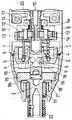
一般に、この種のインパクト回転工具は、図6、7に示す如く、駆動軸1に軸方向でスライド自在に外嵌されてこれと共に回転運動されるハンマー2と、ハンマー2に軸回り方向で着脱自在に噛合されてこれと共に回転運動されるアンビル3と、を備えている。そして、アンビル3にある一定以上の回転負荷が生じた際に駆動軸1の回転運動をハンマー2の後退運動に変換するための機構として、カム溝4を駆動軸1の外周に、ガイド溝5をハンマー2の内周に、鋼球6を同カム溝4とガイド溝5との間に嵌合させて、各々を配設している。又、ハンマー2の後退運動によりこれとアンビル3との噛合が外れた後に再び打撃を伴って同アンビル3と噛合させるための付勢力をハンマー2に付与する弾性部材7を有し、前記各部材をハウジング8内に収容設置してなるものである。 In general, this type of impact rotary tool is, as shown in FIGS. 6 and 7, a
ここでは、モータ(図示せず)から回転力を伝達する出力軸10の先端にピニオンギア11が取り付けられ、このピニオンギア11の外側でこれに噛合される一対のプラネットギア12とハウジング8に固定されたリングギア13とで遊星歯車機構が構成されている。両プラネットギア12は各々軸14を介して駆動軸1に回動自在に固定されており、モータからの回転が遊星歯車機構を介し減速されて同駆動軸1に伝達される。なお、ハウジング8は本体ケース15とその前方先端部分に取り付けられる先端カバー18とでなり、同本体ケース15の内側に前記リングギア13が固定されている。 Here, a
駆動軸1の外周には周方向で二箇所に略V字状のカム溝4が、このV字が後方へ開くような向きにして配置形成されている。同様に、ハンマー2の内周にも周方向で二箇所に略V字状のガイド溝5が、このV字が後方へ開くような向きにして配置され、各々前方へ開放されるように形成されている。相互に対向するカム溝4とガイド溝5との間には、鋼球6が挟み込むようにして嵌合されている。この場合、ハンマー2は駆動軸1に対して相対的に回動しながら前後方向に移動可能であり、又、ハンマー2と駆動軸1との間には圧縮スプリングである弾性部材7が介設されていて同ハンマー2は前方に付勢されている。 On the outer periphery of the
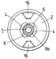
ハンマー2の前方先端面には周方向で二箇所に打撃片16が突設され、両打撃片16はアンビル3と周方向に噛合してこれを打撃するものである。両打撃片16は周方向で180°の間隔をおいて相互対称位置に配設されており、各々後記アンビル3の打撃アーム19と着脱自在に当接噛合されるものである。アンビル3は軸受け17を介してハウジング8の先端カバー18内で回動自在に支持されており、同アンビル3の後端部分には一対の打撃アーム19が相互に180°の間隔で周方向を二等分する位置に外側方へ突出するように配設されている。そして、この両打撃アーム19にハンマー2の打撃片16が同方向から同時に衝突されることで、アンビル3にはネジ締め方向の打撃が与えられる。 Two
なお、駆動軸1はその後端付近が軸受け20で回動自在に支持されると共に、その前端部分がアンビル3の後端面に形成されたガイド穴21に回動自在に挿入嵌合されて支持されている。又、アンビル3の先端部分はハウジング8の先端カバー18から前方へ突出されており、この突出部分に設けられるチャック部22に先端工具としてのドライバビット(図示せず)が着脱自在に装着される。 The
したがって、このインパクト回転工具にあっては、モータが起動されるとその回転が出力軸10及び遊星歯車機構を介して駆動軸1に伝達され、この駆動軸1が回転されるとハンマー2が回転される。ネジ締めに際し、アンビル3に付加される外部トルクが一定トルク以下の状態では、駆動軸1、ハンマー2及び同アンビル3が一体となって回転する。ネジ締めが進行してネジ締め抵抗が大きくなり、アンビル3に付加される外部トルクが一定トルク以上になると、同アンビル3は回転することなく駆動軸1がそのまま回動し続ける状態が瞬間的に発生する。 Therefore, in this impact rotating tool, when the motor is started, the rotation is transmitted to the
このとき、駆動軸1とハンマー2との間には鋼球6が両者のカム溝4及びガイド溝5の間で嵌合保持されているため、同ハンマー2はその両打撃片16を各々打撃アーム19に係合させた状態のままで弾性部材7の付勢力に抗して後退しながら駆動軸1に対し反ネジ締め方向に回動して、その際、両鋼球6が同カム溝4の開き端側へ移動する。アンビル3に付加されるネジ締めトルクがさらに大きくなると、ハンマー2は後退を続け、このハンマー2の打撃片16と同アンビル3の打撃アーム19との係合状態が徐々に浅くなり、最終的にはこの係合状態が解除される。 At this time, since the
前記係合状態が解除されると、ハンマー2は弾性部材7の付勢力によって駆動軸1に対し前進しながらネジ締め方向に回動し、同ハンマー2の打撃片16がアンビル3の打撃アーム19に衝突してこのアンビル3を打撃し、その際、両鋼球6はカム溝4の閉じ中側へ移動する。このように、ハンマー2がアンビル3を打撃する動作を繰り返すことで、同アンビル3はネジ締め方向に繰り返し回動し、ねじが徐々に締め込まれていく。 When the engaged state is released, the
しかしながら、高負荷作業となるボルト締め作業等にあっては、アンビル3がほとんど回転せずロック状態となるため、ハンマー2がアンビル3を打撃する際の反発力が木材へのネジ締め作業等の場合よりも相当に大きくなる。そのため、ハンマー2はカム溝4及びガイド溝5により、反ネジ締め方向に回動しながら急激に後退する。カム溝4及びガイド溝5によって決定されるハンマー2の後退限界以内で、この後退するエネルギーが弾性部材7の弾性エネルギーに全て変換されると、同ハンマー2は後退を停止してネジ締め方向に回動しながら前進を開始し、再びアンビル3を打撃することによりボルトを締め付けていく。 However, in a bolting operation or the like, which is a high load operation, the
そして、このような場合、ボルトとソケットとの噛み込み等の突発的に発生する過大負荷状態時に、ハンマー2の後退を許容量以内で抑えられずに同ハンマー2が鋼球6を介して駆動軸1に対し衝撃を与えた際、この衝撃を緩和する手段が施されていないため、信頼性や操作性等の点で問題がある。又、突発的に発生する過大負荷状態を踏まえてカム溝4やガイド溝5や弾性部材7等の仕様を設定すると、通常作業時の性能が損なわれるという問題を生じる。 In such a case, the
ところで、本出願人は、この種のインパクト回転工具において、高負荷作業を迅速に行う場合であっても、振動や破損等の発生が防止されるものを提案しており(特開2003−71736号公報参照)、このものは、ハウジング内面にハンマーの後退を規制する弾性体を備えたものである。この場合、駆動軸のカム溝とハンマーのガイド溝との間に嵌合される鋼球が衝突を生じる前に、弾性体がクッション性を備えてハンマーの後退を停止させるので、振動の増加及び部品の破損等が一応は防止される。 By the way, the present applicant has proposed an impact rotary tool of this type in which occurrence of vibration, breakage, etc. is prevented even when high-load work is performed quickly (Japanese Patent Application Laid-Open No. 2003-71736). This is provided with an elastic body for restricting the retraction of the hammer on the inner surface of the housing. In this case, before the steel ball fitted between the cam groove of the drive shaft and the guide groove of the hammer causes a collision, the elastic body has a cushioning property and stops the hammer from retreating. Damage to parts is prevented for the time being.
しかしながら、この場合、駆動軸のカム溝とハンマーのガイド溝との間に嵌合される鋼球が衝突を生じないようにしているものであり、同衝突による衝撃を緩和しているものではなく、ハンマーによる衝撃だけを緩和しているものであって、駆動軸そのものの振動やこの駆動軸のカム溝、これと嵌合される鋼球、ハンマーのガイド溝等の部位の破損が十分には防止されないものである。又、ハンマーの後退移動を規制するものであるため、同ハンマーの前後方向の移動ストロークが減少して、打撃のために要する本来の衝撃力までもが低下してしまい、工具としての性能や信頼性が損なわれるものである。
本願発明は、上記従来の技術に鑑みて発明されたものであり、その課題は、駆動軸にかかる衝撃を緩和することで、ハンマーが鋼球を介し同駆動軸に衝突した際の振動を低減して、工具の性能を損なうことなく信頼性及び操作性を向上させることのできるインパクト回転工具を提供することである。 The present invention has been invented in view of the above prior art, and its problem is to reduce the vibration when a hammer collides with the drive shaft via a steel ball by reducing the impact on the drive shaft. Then, it is providing the impact rotary tool which can improve reliability and operativity, without impairing the performance of a tool.
上記課題を解決するために、本願発明のインパクト回転工具では、駆動軸の後端付近にこれを前方へと付勢する弾性体を設けて、ハンマーの後退運動が後退限界に達した際に、駆動軸、ハンマー、鋼球、弾性部材で構成されるブロックが同弾性体の付勢力に抗して後退し得るようになしている。 In order to solve the above problem, in the impact rotary tool of the present invention, an elastic body that urges the drive shaft forward is provided near the rear end of the drive shaft, and when the hammer retreating movement reaches the retreat limit, A block composed of a drive shaft, a hammer, a steel ball, and an elastic member is configured to be able to retract against the urging force of the elastic body.
したがって、本願発明のインパクト回転工具においては、ハンマーの後退運動が後退限界に達した際に、駆動軸、ハンマー、鋼球、弾性部材で構成されるブロックが後退し得るので、同ハンマーは所定のストロークで後退し、カム溝とガイド溝とその間の鋼球とで構成される機構も通常通りに機能して、工具の性能や信頼性が損なわれることはない。そして、駆動軸の後端付近にこれを前方へと付勢する弾性体が設けられているので、ハンマーの後退運動が後退限界に達した際、駆動軸、ハンマー、鋼球、弾性部材で構成されるブロックは、同弾性体の付勢力によってその際の衝撃力や振動が吸収緩和され、工具の操作性が向上されて各部品の破損も確実に防止される。 Therefore, in the impact rotary tool of the present invention, when the retracting movement of the hammer reaches the retracting limit, the block composed of the drive shaft, the hammer, the steel ball, and the elastic member can be retracted. The mechanism which is retracted by the stroke and is constituted by the cam groove, the guide groove and the steel ball between them functions as usual, and the performance and reliability of the tool are not impaired. And since the elastic body that urges it forward is provided near the rear end of the drive shaft, it is composed of the drive shaft, hammer, steel ball, and elastic member when the backward movement of the hammer reaches the backward limit In the block, the impact force and vibration at that time are absorbed and relaxed by the urging force of the elastic body, the operability of the tool is improved, and breakage of each component is reliably prevented.
図1〜5は、本願発明の一実施形態であるインパクト回転工具を示している。この実施形態のインパクト回転工具は、駆動軸1に軸方向でスライド自在に外嵌されてこれと共に回転運動されるハンマー2と、ハンマー2に軸回り方向で着脱自在に噛合されてこれと共に回転運動されるアンビル3と、を備えている。そして、アンビル3にある一定以上の回転負荷が生じた際に駆動軸1の回転運動をハンマー2の後退運動に変換するための機構として、カム溝4を駆動軸1の外周に、ガイド溝5をハンマー2の内周に、鋼球6を同カム溝4とガイド溝5との間に嵌合させて、各々を配設している。又、ハンマー2の後退運動によりこれとアンビル3との噛合が外れた後に再び打撃を伴って同アンビル3と噛合させるための付勢力をハンマー2に付与する弾性部材7を有し、前記各部材をハウジング8内に収容設置してなるものである。 1-5 has shown the impact rotary tool which is one Embodiment of this invention. The impact rotary tool of this embodiment is externally fitted to the
このようなインパクト回転工具において、駆動軸1の後端付近にこれを前方へと付勢する弾性体9aを設けて、ハンマー2の後退運動が後退限界に達した際に、駆動軸1、ハンマー2、鋼球6、弾性部材7で構成されるブロックが同弾性体9aの付勢力に抗して後退し得るようになしている。そして、駆動軸1の前端付近にもアンビル3との間で同駆動軸1を後方へと付勢する弾性体9bを介設している。 In such an impact rotary tool, an
以下、この実施形態のインパクト回転工具を、より具体的詳細に説明する。この実施形態のインパクト回転工具では、モータMから回転力を伝達する出力軸10の先端にピニオンギア11が取り付けられ、このピニオンギア11の外側でこれに噛合される一対のプラネットギア12とハウジング8に固定されたリングギア13とで遊星歯車機構が構成されている。両プラネットギア12は各々軸14を介して駆動軸1に回動自在に固定されており、モータMからの回転が遊星歯車機構を介し減速されて同駆動軸1に伝達される。なお、ハウジング8は本体ケース15とその前方先端部分に取り付けられる先端カバー18とでなり、同本体ケース15の内側に前記リングギア13が固定されている。又、図5に示す如く、本体ケース15にはハンドル部23が一体に垂設されており、このハンドル部23を手で握ってネジ締め作業が行われるものであり、その際、同ハンドル部23の基端部付近の前側に設けられたスイッチ24を操作して、モータMは駆動開始・停止されるものである。 Hereinafter, the impact rotary tool of this embodiment will be described in more detail. In the impact rotary tool of this embodiment, a
駆動軸1の外周には周方向で二箇所に略V字状のカム溝4が、このV字が後方へ開くような向きにして配置形成されている。同様に、ハンマー2の内周にも周方向で二箇所に略V字状のガイド溝5が、このV字が後方へ開くような向きにして配置され、各々前方へ切欠状に開放されるように形成されている。相互に対向するカム溝4とガイド溝5との間には、鋼球6が挟み込むようにして嵌合されている。この場合、ハンマー2は駆動軸1に対して相対的に回動しながら前後方向に移動可能であり、又、ハンマー2と駆動軸1との間には圧縮スプリングである弾性部材7が介設されていて同ハンマー2は前方に付勢されている。 On the outer periphery of the
ハンマー2の前方先端面には周方向で二箇所に打撃片16が突設され、両打撃片16はアンビル3と周方向に噛合してこれを打撃するものである。両打撃片16は周方向で180°の間隔をおいて相互対称位置に配設されており、各々後記アンビル3の打撃アーム19と着脱自在に当接噛合されるものである。アンビル3は軸受け17を介してハウジング8の先端カバー18内で回動自在に支持されており、同アンビル3の後端部分には一対の打撃アーム19が相互に180°の間隔で周方向を二等分する位置に外側方へ突出するように配設されている。そして、この両打撃アーム19にハンマー2の打撃片16が同方向から同時に衝突されることで、アンビル3にはネジ締め方向の打撃が与えられる。 Two hammering
なお、駆動軸1はその後端付近が軸受け20で回動自在に支持されると共に、その前端部分がアンビル3の後端面に形成されたガイド穴21に回動自在に挿入嵌合されて支持されている。そして、駆動軸1と軸受け20との間に圧縮スプリングである弾性体9aが、同駆動軸1の前端面とガイド穴21の内底面との間に圧縮スプリングである弾性体9bが、各々介在配設されている。この場合、弾性体9aは駆動軸1に外嵌され、弾性体9bはガイド穴21に収容されて、各々保持されており、同駆動軸1は両弾性体9a、9bの付勢力が均衡する状態で前後方向進退自在に支持されている。又、アンビル3の先端部分はハウジング8の先端カバー18から前方へ突出されており、この突出部分に設けられるチャック部22に先端工具としてのドライバビット(図示せず)が着脱自在に装着される。 The
したがって、このインパクト回転工具にあっては、モータMが起動されるとその回転が出力軸10及び遊星歯車機構を介して駆動軸1に伝達され、この駆動軸1が回転されるとハンマー2が回転される。ネジ締めの初期段階であって、アンビル3に付加される外部トルクが一定トルク以下の状態では、駆動軸1、ハンマー2及び同アンビル3が一体となって回転する。ネジ締めが進行してネジ締め抵抗が大きくなり、アンビル3に付加される外部トルクが一定トルク以上になると、同アンビル3は回転することなく駆動軸1がそのまま回動し続ける状態が瞬間的に発生する。 Therefore, in this impact rotating tool, when the motor M is started, the rotation is transmitted to the
このとき、駆動軸1とハンマー2との間には鋼球6が両者のカム溝4及びガイド溝5の間で嵌合保持されているため、同ハンマー2はその両打撃片16を各々打撃アーム19に係合させた状態のままで弾性部材7の付勢力に抗して後退しながら駆動軸1に対し反ネジ締め方向に回動して、その際、両鋼球6が同カム溝4の開き端側へ移動する。アンビル3に付加されるネジ締めトルクがさらに大きくなると、ハンマー2は後退を続け、このハンマー2の打撃片16と同アンビル3の打撃アーム19との係合状態が徐々に浅くなり、最終的にはこの係合状態が解除される。 At this time, since the
前記係合状態が解除されると、ハンマー2は弾性部材7の付勢力によって駆動軸1に対し前進しながらネジ締め方向に回動し、同ハンマー2の打撃片16がアンビル3の打撃アーム19に衝突してこのアンビル3を打撃し、その際、両鋼球6はカム溝4の閉じ中側へ移動する。このように、ハンマー2がアンビル3を打撃する動作を繰り返すことで、同アンビル3はネジ締め方向に繰り返し回動し、ねじが徐々に締め込まれていく。 When the engaged state is released, the
ネジ締め等の比較的小さな負荷作業にあっては、ハンマー2がカム溝4及びガイド溝5で構成される軸方向後退量内で前後進退動作を繰り返すが、高負荷作業となるボルト締め作業等において、特に、ボルトとソケットとが噛み込む等の突発的な過大負荷状態が発生すると、ハンマー2の後退動作は前記軸方向後退量内で納まらず、同ハンマー2が鋼球6を介して駆動軸1のカム溝4の開き側端部に当接するという状態が発生する。その際、駆動軸1は鋼球6から後方へ押圧される力を受け、ハンマー2、鋼球6、弾性部材7と一体的なブロックとなって、弾性体9aの付勢力に抗して後退する(図3、4参照)。 For relatively small load operations such as screw tightening, the
この場合、ハンマー2は所定のストロークで後退し、カム溝4とガイド溝5とその間の鋼球6とで構成される機構も通常通りに機能して、工具の性能や信頼性が損なわれることはない。しかも、駆動軸1の後端付近にこれを前方へと付勢する弾性体9aが設けられていることで、前記の如く、ハンマー2の後退運動が後退限界に達した際、駆動軸1、ハンマー2、鋼球6、弾性部材7で一体的に構成されるブロックは、同弾性体9aの付勢力によってその際の衝撃力や振動が吸収緩和され、工具の操作性が向上されて各部品の破損も確実に防止される。 In this case, the
すなわち、前記一体的に後退するブロックの後退移動するときの運動エネルギーが弾性体9aの弾性エネルギーに全て変換されると、同一体ブロックは後退を停止して逆方向に前進する。この動作により駆動軸1のカム溝4と鋼球6とが当接した場合、同駆動軸1のカム溝4の開き側端部にかかる衝撃力は低減され、同駆動軸1への負荷が緩和されると共に当接時に発生する振動も抑えられる。又、駆動軸1の前端付近にアンビル3との間で同駆動軸1を後方へと付勢する弾性体9bが介設されていて、前記一体ブロックは同弾性体9bの付勢力に抗して徐々に前進し、その後、前記弾性体9aと同様の作用により前進を停止して再び後退する。この一体ブロックの前進後退運動は時間が経過するにつれて減衰し、アンビル3に衝撃的な力を与えることなくスムーズに元の位置に復帰する。 That is, when all of the kinetic energy when the block that moves backward integrally is converted into the elastic energy of the
又、前記駆動軸1の前後に配設される両弾性体9a、9bの固有振動数を、ある一定のインパクト打撃周波数(ハンマー2がアンビル3を打撃する周波数)と共振するように設定することによって、更なる効果が期待される。すなわち、両弾性体9a、9bの仕様をこのように設定すると、駆動軸1、ハンマー2、鋼球6、弾性部材7で構成される前記一体ブロックの前進後退運動が増幅されて、アンビル3は軸方向に押し付けられつつ軸方向に微小振動を発生した状態でハンマー2により打撃される。 Also, the natural frequency of both
例えば、ネジ締め作業のように主として木材を対象部材とする作業においては、アンビル3が押し付けられながら軸方向に微小振動することで、このアンビル3の先端部分に取り付けられるドライバービットを介して押し付け且つ微小振動させながらねじを締め付けていくことが可能になる。これにより、ねじは対象部材を掘削しながら締め付けられていくことになって、同ねじと対象部材との摩擦抵抗が低下し、より効率良くネジ締め作業を行うことが可能となる。又、ハンマー2がアンビル3を打撃する瞬間に、このアンビル3はねじを押し付けているため、ドライバービットがねじ頭から離脱し難くなって作業性は更に向上する。 For example, in an operation using mainly wood as a target member such as a screw tightening operation, the
又、ボルト締め等の主として鉄板を対象部材とする作業においては、前記のようにアンビル3が微小振動すると、ドライバービット、ソケット、ボルトを介して鉄板にこの振動が伝わり、作業時の騒音の原因となる。そのため、駆動軸1の前後に配設される前記両弾性体9a、9bの固有振動数を、大負荷時のインパクト打撃周波数(ボルト締め等の高負荷作業時にハンマー2がアンビル3を打撃する周波数)から積極的に外れるように設定することによって、作業時の騒音を低減することができる。 In addition, in the work that mainly uses an iron plate such as bolt fastening, if the
1 駆動軸
2 ハンマー
3 アンビル
4 カム溝
5 ガイド溝
6 鋼球
7 弾性部材
8 ハウジング
9a 弾性体
9b 弾性体1 Drive
9a Elastic body
9b Elastic body
Claims (4)
Translated fromJapanesePriority Applications (1)
| Application Number | Priority Date | Filing Date | Title |
|---|---|---|---|
| JP2003297800AJP2005066728A (en) | 2003-08-21 | 2003-08-21 | Impact rotating tool |
Applications Claiming Priority (1)
| Application Number | Priority Date | Filing Date | Title |
|---|---|---|---|
| JP2003297800AJP2005066728A (en) | 2003-08-21 | 2003-08-21 | Impact rotating tool |
Publications (1)
| Publication Number | Publication Date |
|---|---|
| JP2005066728Atrue JP2005066728A (en) | 2005-03-17 |
Family
ID=34403524
Family Applications (1)
| Application Number | Title | Priority Date | Filing Date |
|---|---|---|---|
| JP2003297800APendingJP2005066728A (en) | 2003-08-21 | 2003-08-21 | Impact rotating tool |
Country Status (1)
| Country | Link |
|---|---|
| JP (1) | JP2005066728A (en) |
Cited By (5)
| Publication number | Priority date | Publication date | Assignee | Title |
|---|---|---|---|---|
| JP2010184332A (en)* | 2009-02-13 | 2010-08-26 | Hitachi Koki Co Ltd | Fastening tool |
| JP2014138958A (en)* | 2007-11-09 | 2014-07-31 | Vamco Internatl Inc | Drive apparatus and operation method for press machine |
| CN105829027A (en)* | 2013-12-20 | 2016-08-03 | 日立工机株式会社 | Impact tool |
| JP2016175144A (en)* | 2015-03-19 | 2016-10-06 | パナソニックIpマネジメント株式会社 | Impact tool |
| WO2018155074A1 (en)* | 2017-02-27 | 2018-08-30 | 工機ホールディングス株式会社 | Screw tightening tool |
- 2003
- 2003-08-21JPJP2003297800Apatent/JP2005066728A/enactivePending
Cited By (6)
| Publication number | Priority date | Publication date | Assignee | Title |
|---|---|---|---|---|
| JP2014138958A (en)* | 2007-11-09 | 2014-07-31 | Vamco Internatl Inc | Drive apparatus and operation method for press machine |
| JP2010184332A (en)* | 2009-02-13 | 2010-08-26 | Hitachi Koki Co Ltd | Fastening tool |
| CN105829027A (en)* | 2013-12-20 | 2016-08-03 | 日立工机株式会社 | Impact tool |
| JP2016175144A (en)* | 2015-03-19 | 2016-10-06 | パナソニックIpマネジメント株式会社 | Impact tool |
| WO2018155074A1 (en)* | 2017-02-27 | 2018-08-30 | 工機ホールディングス株式会社 | Screw tightening tool |
| JPWO2018155074A1 (en)* | 2017-02-27 | 2019-07-11 | 工機ホールディングス株式会社 | Screw tightening tool |
Similar Documents
| Publication | Publication Date | Title |
|---|---|---|
| US7455121B2 (en) | Power tool | |
| TWI354612B (en) | Impact wrench | |
| JP2008080485A (en) | Mechanical hammer | |
| JP4702027B2 (en) | Hammer drill | |
| JP2828640B2 (en) | Rotary impact tool | |
| JP4552843B2 (en) | Hammer tool adapter | |
| JP4509890B2 (en) | Impact type work tool | |
| JP2005066728A (en) | Impact rotating tool | |
| JP2009172732A (en) | Impact rotary tool | |
| JP2013208678A (en) | Impact tool | |
| JP5022725B2 (en) | Impact type work tool | |
| JP2014069266A (en) | Rotary impact tool | |
| JP2003181774A (en) | Impact tool | |
| JP2002273666A (en) | Rotary impact tool | |
| JP2004249422A (en) | Rotary impact tool | |
| JP2013022691A (en) | Impact rotary tool | |
| JP2006175553A (en) | Impact rotary tool | |
| JP3815686B2 (en) | Electric tool | |
| JP6638856B2 (en) | Screw tightening tool | |
| JP5403309B2 (en) | Rotating hammer tool | |
| JP4399864B2 (en) | Electric tool | |
| JP4056041B2 (en) | Electric tool | |
| JP7094036B2 (en) | Impact tool | |
| JP6455227B2 (en) | Impact tool | |
| JP2014188612A (en) | Impact tool |