JP2005065728A - Similar image retrieval system - Google Patents
Similar image retrieval systemDownload PDFInfo
- Publication number
- JP2005065728A JP2005065728AJP2003208526AJP2003208526AJP2005065728AJP 2005065728 AJP2005065728 AJP 2005065728AJP 2003208526 AJP2003208526 AJP 2003208526AJP 2003208526 AJP2003208526 AJP 2003208526AJP 2005065728 AJP2005065728 AJP 2005065728A
- Authority
- JP
- Japan
- Prior art keywords
- image
- image data
- similar
- subject
- information
- Prior art date
- Legal status (The legal status is an assumption and is not a legal conclusion. Google has not performed a legal analysis and makes no representation as to the accuracy of the status listed.)
- Pending
Links
Images


Landscapes
- Image Analysis (AREA)
- Medical Treatment And Welfare Office Work (AREA)
- Measuring And Recording Apparatus For Diagnosis (AREA)
- Processing Or Creating Images (AREA)
- Information Retrieval, Db Structures And Fs Structures Therefor (AREA)
Abstract
Description
Translated fromJapanese【0001】
【発明の属する技術分野】
本発明は、処理対象の画像と類似している画像を検索する類似画像検索装置に関するものである。
【0002】
【従来の技術】
従来より、開業医や病院等の医療施設において、種々の医療画像、すなわち、X線画像、CT画像、MR画像等が撮影され利用されている。このような医療画像は、患者の病状の診断や経過観察、治癒または進行状態の把握などのために用いられ、通常、医師等の読影者が画像を見ながら診断を行い治療方針の決定などを行っている。
【0003】
医療施設では、従来、診断の際に使用したこのような医療画像をハードコピーの状態で保管していることが多かったが、日々増加し続ける医療画像の管理を簡易にするために、また保管スペースの削減のために、医療画像等の画像からデジタル画像を生成し、画像データの形で光ディスク、磁気ディスク等の記録媒体に記録して保存する画像ファイリング装置が提案されている。
【0004】
この装置を活用すれば、医療画像の保管スペースの削減が実現できるだけでなく、画像を画像データの形で管理することができるので、画像を種々の目的のために利用することが可能になる。
【0005】
ところで、上述したように、画像診断を行う際には、医師等の読影者が画像を見ながら診断を行っているが、読影者の経験が浅い場合や、或いは経験があっても診断の対象となる画像が珍しい症例であったり、得意分野以外のものであったりしたときなどには、医師が疾患名を適正に判断することが難しい場合がある。このようなときには、他の医師の意見を聞いたり、過去の類似している症例や診断結果を参照したりして、診断や治療方針の決定を行うことがあったが、診断対象の画像と類似している症例を、ハードコピーの状態で保管されている多数の過去の画像の中から的確に探すことは非常に困難であり、また、例えば開業医等の小規模な医療施設においては、過去の症例が少ないため、所望の類似症例を探すことができるとは限らない。そこで、多数の症例の中から、診断対象の画像に類似している症例を的確に探索できるようにすることが望まれている。
【0006】
この要望に応えるための一つの技術として、過去の症例の中から診断対象の画像に類似した画像を検索して出力する類似画像検索手法が各種提案されているが、これらの検索手法によれば、検索対象となる画像のテクスチャ情報(濃淡パターンを表す情報)に基づいて、過去の症例の画像と診断対象の画像との類似度を算出し、その類似度に基づいて類似性の高い画像を診断対象の画像に類似した類似画像として検索している。
【0007】
【発明が解決しようとする課題】
しかしながら、上述のように、テクスチャ情報のみに基づいて画像の類似性を観る手法では、画像中の被写体形状がわずかに異なっていたり、背景にノイズや非被写体部分、いわゆる「すぬけ」が混入していたりする場合には、別の種類の画像と認識され、類似性が低いと判定されてしまうおそれがある。
【0008】
本発明は、上記事情に鑑み、多数の画像の中から診断対象の画像と類似した画像をより的確に検索することを可能にした類似画像検索装置を提供することを目的とするものである。
【0009】
【課題を解決するための手段】
本発明による類似画像検索装置は、被写体画像を表す画像データとして、多数の被写体の形状情報およびテクスチャ情報が保存されている画像データベースと、検索対象となる被写体画像を表す画像データを入力する画像データ入力手段と、画像データ入力手段により入力された画像データに基づいて、入力された画像データが表す被写体画像に含まれる被写体の形状情報およびテクスチャ情報を抽出する抽出手段と、画像データベースに保存されている画像データが表す被写体画像に含まれる被写体の形状情報およびテクスチャ情報と、入力された画像データが表す被写体画像に含まれる被写体の形状情報およびテクスチャ情報とを比較することにより、両被写体画像の類似度を算出する類似度算出手段と、類似度に基づいて、画像データベースに保存されている画像データの中から、入力された画像データが表す被写体画像と類似した被写体画像を表す類似画像データを検索する検索手段と、検索手段による検索結果を表す検索結果情報を出力する出力手段とを備えたことを特徴とするものである。
【0010】
なお、形状情報およびテクスチャ情報としては、被写体の形状およびテクスチャの固有成分を表すものとしてもよい。
【0011】
固有成分とは、被写体の形状及びテクスチャを表現することができる、複数の固有成分軸で構成された多次元空間において、被写体の形状およびテクスチャの各固有成分軸への投影値(各固有成分軸での大きさ)を意味するものである。固有成分軸は、多数の被写体画像を標本として、被写体の形状およびテクスチャに対してそれぞれ主成分分析を行うことにより算出される複数の固有形状および複数の固有テクスチャに対応する軸であり、個々の被写体は、その形状を固有形状の線形和、すなわち固有形状を表す固有成分の組み合わせとして、また、そのテクスチャを固有テクスチャの線形和、すなわち固有テクスチャを表す固有成分の組み合わせとして表現することができる。
【0012】
出力手段により出力される検索結果情報とは、検索された類似画像データを意味するものとしてもよいが、入力された画像データが表す被写体画像と類似した被写体画像を表す類似画像データが画像データベースの中から見つからなかった場合には、見つからなかった旨を示す「類似画像が存在しません」等のメッセージを検索結果情報としてもよい。
【0013】
また、本発明の類似画像検索装置を、画像データベースに保存されている画像データに関連する診断データを保存している診断データベースをさらに備え、検索手段が、検索された類似画像データに関連する診断データを診断データベースの中から検索し、出力手段が、検索された診断データを、関連する類似画像データとともに検索結果情報として出力するものとすることもできる。
【0014】
なお、診断データとは、診断に関連する種々の情報を意味するものであり、例えば、疾患名、治療方針、所見、患者名、担当医師名、撮影日時、経過観察情報などが挙げられる。
【0015】
また、本発明の類似画像検索装置は、抽出手段により抽出された形状情報およびテクスチャ情報を、入力された画像データとともに画像データベースに登録する登録手段をさらに備えたものとすることができる。
【0016】
【発明の効果】
上記のように構成された本発明の類似画像検索装置によれば、被写体画像を表す画像データを多数保存している画像データベースの中から、入力された画像データが表す被写体画像と類似した被写体画像を表す類似画像データを、テクスチャ情報だけでなく形状情報およびテクスチャ情報の双方に基づいて検索し、検索結果を出力することができるので、被写体の形状の違いや「すぬけ」の混入による類似判定への影響を抑え、より的確に類似画像を検索することができる。
【0017】
なお、類似画像データとともに、その画像データに関連する診断データを出力するものとすれば、医師等が画像の読影時に診断に迷ったときに有効な診断支援情報を提供することができる。
【0018】
また、入力された画像データから抽出された被写体の形状情報およびテクスチャ情報を、その入力された画像データとともに画像データベースに登録する登録手段を設ければ、類似画像データを蓄積して保存することができ、より多数の症例を備えることができるので、さらに診断に有効なものとすることができる。
【0019】
【発明の実施の形態】
以下、本発明の類似画像検索装置の実施の形態を図面に基づいて説明する。図1は本発明における類似画像検索装置を含む類似画像検索システムの構成図である。
【0020】
本実施形態による類似画像検索システムは、読み取った医用画像P中の病変部を公知の画像解析処理により検出し、病変部を中心に病変部上に関心領域(ROI)を設定して、その設定したROI画像データP′を出力するCAD(計算機支援画像診断装置)10と、CAD10から送られるROI画像データP′を入力する画像データ入力手段20と、病変部の画像を表す画像データとしての病変部の形状情報およびテクスチャ情報や診断に関連する診断データを保存している症例データベース30と、画像データ入力手段20により入力されたROI画像データP′に基づいて、ROI画像データP′が表す病変部の形状情報およびテクスチャ情報を抽出する抽出手段40と、症例データベース30に保存されている画像データが表す病変部の形状情報およびテクスチャ情報と、ROI画像データP′が表す病変部の形状情報およびテクスチャ情報とを比較することにより、両病変部の類似度Rを算出する類似度算出手段50と、類似度Rに基づいてROI画像データP′が表す病変部と類似した類似画像データとその類似画像データに関連する診断データを症例データベース30から検索して読み込む検索手段60と、検索手段50による検索結果を表す検索結果情報(読み込まれた類似画像データおよび診断データ)を後述の表示手段80に出力する出力手段70と、出力手段70により出力された検索結果情報をモニタ画面上に表示させる表示手段80と、抽出手段40により抽出されたROI画像データP′が表す病変部の形状情報、テクスチャ情報およびその病変部の診断結果を症例データベース30に登録する登録手段90とにより構成されている。
【0021】
症例データベース30は、病変部画像を表す画像データとしての病変部の形状情報およびテクスチャ情報を多数保存している画像データベース30aと、各画像データに関連する診断データを保存している診断データベース30bとにより構成されている。画像データベース30aには、過去に診断された種々の病変部の多数の画像データが保存されており、また、診断データベース30bには、画像データベース30aに保存されている各画像データに関連する診断データが、各画像データと関連付けられた状態で保存されている。また、診断データとしては、疾患名、治療方針、所見、担当医師名、撮影日時、経過観察情報など、診断に関する種々のデータが記録されている。
【0022】
登録手段90は、抽出手段40により抽出されたROI画像データP′が表す病変部の形状情報およびテクスチャ情報をROI画像データP′とともに画像データベース30aに登録し、また、ROI画像データP′が表す病変部の診断結果を画像データP′と関連付けて診断データベース30bに登録する。
【0023】
次に、以上のように構成された本実施形態の類似画像検索システムの作用について説明する。
【0024】
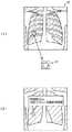
図2(1)に示すような病変部(腫瘤)を含んだ胸部画像を表す画像データPがCAD10により読み込まれ、胸部画像P(簡単のため、画像データとその画像データが担持する画像に同じ符号を付して説明する)がモニタ画面上に表示される。胸部画像Pの右肺部分には病変部(腫瘤)と疑われる円形の陰影が表れている。この胸部画像Pに対し、オペレータが、病変部の位置および範囲を検出すべく、病変部の検出を指示すると、CAD10は、病変部としての特徴的な形状(例えば、孤立した円形の陰影)、あるいは濃淡パターン(例えば、全体的に輝度が高い)を有する領域を画像解析処理により自動的に検出し、その領域をROIとして設定する。図2(1)中のP′は、その胸部画像P中のROIを示すROI画像P′を示したものである。このように設定されたROIの画像データP′が画像データ入力手段20により入力される。なお、ROI画像は、胸部画像Pの画像診断を行う医師等の読影者により指定され抽出された画像であってもよく、この場合は、ROI画像の指定は図示しないマウス等の位置指示手段を用いて行われる。
【0025】
画像データ入力手段20によりROI画像データP′が入力されると、抽出手段40は、まず、入力されたROI画像データP′が表すROI画像P′に対し、エッジ検出を行って、病変部の大まかな輪郭形状を抽出する。例えば、ROIの中心から周辺に向けて放射線状に画素値の急峻な変化(エッジ)を探索して、病変部の輪郭形状を抽出する。このとき、病変部を図3(1)に示すような典型的な形状パターン(例えば4つのパターン)に分類し、ROI画像P′中の病変部がどの形状パターンに当てはまるか判別する。例えば、ROI画像P′中の病変部の輪郭形状を図4に示すように極座標変換して曲線Vを作成し、図3(2)に示すような、それぞれの典型的な形状パターンを極座標変換した場合の曲線V1〜V4と、θ方向にシフトさせながらマッチングを行い、最も差分の少ないものをこの病変部の形状パターンとして選択する。このように病変部を典型的な形状パターンに分類することで、より正確な被写体の形状情報及びテクスチャ情報の抽出や、検索範囲の絞り込みができるため、より的確で効率的な類似画像検索が可能となる。
【0026】
続いて、ROI画像P′が表す病変部の形状情報およびテクスチャ情報を抽出する。病変部の形状情報およびテクスチャ情報を抽出する手法としては、マンチェスター大学のCootesらが提案している“Active Appearance Model(AAM)”[T.F. Cootes, and C.J. Taylor, Active Appearance Models, Proc. European Conference on Computer Vision, Vol.2, pp.484−498, Springer, 1998]を応用する。このAAMの手法に基づく形状変化モデルおよびテクスチャ変化モデルを利用することにより、病変部の形状およびテクスチャを複数の固有形状および固有テクスチャと呼ばれるベクトルの線形和でそれぞれ表現することができる。
【0027】
これら複数の固有形状および固有テクスチャのそれぞれに対応する形状固有成分軸およびテクスチャ固有成分軸(総称して固有成分軸という)を設定すれば、個々の病変部の形状およびテクスチャは各固有成分軸上の大きさである固有成分の組み合わせとして表すことができ、すなわち、これらの固有成分軸からなる多次元空間におけるベクトルとして表現することができる。本実施形態においては、病変部の形状情報およびテクスチャ情報を、この固有成分の組み合わせ、あるいは多次元空間内のベクトルとして表す。
【0028】
以下に、形状変化モデルおよびテクスチャ変化モデルの作成手順と、それを利用して、入力されたROI画像P′が表す病変部の形状情報およびテクスチャ情報を抽出する手順について説明する。なお、これらの変化モデルは、形状パターンで分類した画像データベース30a中の画像データに基づいて、形状パターン毎に作成しておき、入力されたROI画像P′が表す病変部の形状パターンに応じて、これに対応する同種の形状パターンの変化モデルを使うものとする。
【0029】
(平均形状・平均テクスチャの作成)◎
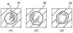
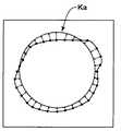
まず、画像データベース30a中の各画像データが表す病変部画像から病変部の輪郭形状を複数の点(ランドマーク)として抽出する。図5は、その例として、画像データベース30a中の形状パターンaに分類された病変部画像P1,P2,P3に対して病変部の外縁にランドマークを付した状態を示した図であり、同図中の記号Mで表した複数の点がランドマークである。これらランドマークとして抽出された各病変部画像が表す病変部の形状から病変部の平均形状を作成する。図5は、病変部の平均形状Kaを示す図である。なお、各画像の病変部の形状をランドマークとして抽出する際には、平行成分について予め正規化しておくとよい。例えば、病変部の重心を画像の中心に揃える。
【0030】
次に、画像データベース30a中の画像データが表す各病変部画像を、作成された平均形状にワーピングするために、各病変部画像中のランドマーク各点の平均形状へのシフト量を算出する。図7は、病変部の外縁に付されたランドマーク各点が、平均形状Kaへワーピングされる状態を示した図である。そして、ランドマーク各点のシフト量を、2次元5次多項式を用いて近似する。多項式近似の数式を下記に示す。
【0031】
【数1】
【0032】
上式を用いて、各画像について画素毎の平均形状へのシフト量を算出し、各画像を画素毎に平均形状へワーピングする。このとき、ワープ後の座標が整数ではなく小数点以下を含む位置に移動する画素については、4近傍から1次近似で画素値を求める。つまり、ワープ後の座標を囲む4つの画素に対して、ワープ後の座標から各画像の座標までの距離に比例して画素値をそれぞれ分配するようにする。そして、平均形状へワーピングされた各画像、平均テクスチャが得られる。
【0033】
(形状変化モデルの作成)◎
画像データベース30a中の画像データが表す各病変部画像の形状と平均形状を用いて、病変部の形状に対して主成分分析を行い、固有形状を算出する。固有成分は文献[Matthew Turk, Alex Pentland, Eigenfaces for Recognition, Journal of Cognitive Neuroscience, vol.3, num1, 1991]に示す手法を用いて求める。画像データベース30a中の画像データが表す各病変部画像は、この固有形状の線形和を用いて次式のように近似できる。
【0034】
【数2】
【0035】
(テクスチャ変化モデルの作成)◎
平均形状へワーピングされた各病変部画像のテクスチャと平均テクスチャを用いて、病変部のテクスチャに対して主成分分析を行い、固有テクスチャを算出する。
【0036】
【数3】
【0037】
(形状情報およびテクスチャ情報の抽出)
ROI画像P′が表す病変部の形状をランドマークとして抽出し、この病変部の形状を表す形状ベクトルxroiを得る。そして、式(7)で記述されるような比較用の形状ベクトルxresを設定し、xresの形状係数bsresの組み合わせを調整して、比較用形状ベクトルxresと病変部の形状ベクトルxroiとの差分が最小となる形状係数bsresの組み合わせを探索する。このとき求められた形状係数bsresの組み合わせが、病変部の形状情報としての形状固有成分となる。
【0038】
【数4】
【0039】
【数5】
【0040】
【数6】
【0041】
検索手段60は、症例データベース30から、最も類似度の高い類似画像データとその類似画像データに関連付けされた診断データを読み込み、出力手段70が、表示手段80の画面上にこれらの検索結果情報を表示する。
【0042】
検索手段60により検索された類似画像データは出力手段70により表示手段80に出力され、表示手段80においてモニタ画面上に表示される。図2(2)は、ROI画像データP′に基づいて検索された類似画像データの表示例を示したものである。図示のように、類似画像は円形の病変部を有する画像であり、その診断結果(疾患名:早期肺がん、対応:CTによる精密検査要)がともに表示されている。このように入力された画像データと類似している症例の画像を診断結果とともに表示すれば、診断に迷ったときなどに診断支援となり得る情報を提供することができる。
【0043】
そして、登録手段90は、オペレータからの指示により、抽出手段40にて抽出されたROI画像P′が表す病変部の形状情報およびテクスチャ情報をそのROI画像データP′とともに画像データベース30aに登録保存し、また、オペレータが、このROI画像P′が表す病変部に対する診断結果を入力したときは、その診断結果を画像データP′と関連付けて診断データベースに登録保存することもできる。このように画像データおよび診断データを症例データベース30に蓄積保存すれば、より多数の症例を備えることができるので、さらに診断に有効なものとすることができる。
【0044】
なお、上記実施形態においては、検索手段60により検索される類似画像を1画像のみとしたが、本発明の類似画像検索装置において検索可能な類似画像は1つに限られるものではなく、例えば、類似の度合いが高いものから順に所望の複数画像(3画像、或いは20画像など)を表示させる形態でもよいし、一定の基準以上(数値で表せる場合には類似度80%以上など)のものを表示させる形態でもよい。こうすれば、医師等はいくつかの類似画像の中から診断対象の症例により合ったものを選択することができる。つまり、多くの経験を積んだ医師であっても見落としを完全に防ぐことは難しいため、いくつかの症例を挙げて診断を支援することによりさらに確実な診断が可能になる。
【0045】
また、上記実施形態における表示手段80の表示例としては、上記の他、例えば、類似画像とともに類似度を表示する形態や、類似画像と入力されたROI画像P′との差分を表すサブトラクション画像を合わせて表示する形態、データをカテゴリ分類して各カテゴリの中から最も類似している症例を1つずつ表示する形態など種々の形態が可能である。また、類似度が所定の基準以下(例えば、20%以下など)の類似画像は表示しない形態としてもよい。また、類似画像データがなかったときには、「類似症例が存在しません」等のメッセージを表示することができる。また、類似画像データのカテゴリ分類としては、例えば、画像中に存在している異常陰影の性状(悪性、良性、正常の別)による分類などが考えられる。すなわち、カテゴリ分類せずに類似画像を検索すると悪性の症例しか表示されないこともあるが、正常の症例と悪性の症例からそれぞれ1つ以上の症例を表示させれば、診断結果が異なる症例を比較することができるため、より正確な診断が可能になる。
【0046】
なお、本実施形態においては、胸部画像中の病変部を被写体として扱ったが、これに限らず、乳房画像中の乳癌の病変部など、形状およびテクスチャがある程度定まるものであれば、いかなるものでも扱うことができる。
【図面の簡単な説明】
【図1】本発明の一実施形態による類似画像検索システムの構成図
【図2】検索対象画像および検索結果の表示例を示す図
【図3】病変部の形状パターンと各パターンの極座標表現された曲線を示す図
【図4】病変部の輪郭形状を極座標変換する様子を示す図
【図5】画像データベース30a中の画像データが表す病変部画像の病変部の外縁にランドマークを付した状態を示す図
【図6】画像データベース30a中の画像データが表す病変部画像の病変部の平均形状を示す図
【図7】病変部の形状を平均形状へワーピングする様子を示す図
【図8】病変部の固有形状の例を示す図
【図9】病変部の固有テクスチャの例を示す図
【符号の説明】
1 類似画像検索システム
10 CAD
20 画像データ入力手段
30 症例データベース
30a 画像データベース
30b 診断データベース
40 抽出手段
50 類似度算出手段
60 検索手段
70 出力手段
80 表示手段
90 登録手段[0001]
BACKGROUND OF THE INVENTION
The present invention relates to a similar image retrieval apparatus that retrieves an image similar to an image to be processed.
[0002]
[Prior art]
Conventionally, various medical images, that is, X-ray images, CT images, MR images, and the like have been taken and used in medical facilities such as practitioners and hospitals. Such medical images are used for diagnosing the patient's medical condition, observing follow-up, grasping the healing or progress status, etc., and usually a doctor or other interpreter makes a diagnosis while observing the image to determine the treatment policy. Is going.
[0003]
Traditionally, medical facilities used to store such medical images used for diagnosis in hard copies. However, in order to simplify the management of medical images, which are increasing daily, they are stored again. In order to save space, an image filing device has been proposed in which a digital image is generated from an image such as a medical image, and is recorded and stored in a recording medium such as an optical disk or a magnetic disk in the form of image data.
[0004]
By utilizing this apparatus, not only can the storage space for medical images be reduced, but the images can be managed in the form of image data, so that the images can be used for various purposes.
[0005]
By the way, as described above, when performing image diagnosis, an interpreter such as a doctor makes a diagnosis while looking at the image. However, if the image reader has little experience or has experience, the object of diagnosis When the image to become is a rare case or something other than the specialty field, it may be difficult for the doctor to properly determine the disease name. In such cases, the diagnosis and treatment policy may be determined by listening to the opinions of other doctors or referring to similar cases and diagnosis results in the past. It is very difficult to accurately search for similar cases from a large number of past images stored in hard copy, and in a small medical facility such as a practitioner, the past Because there are few cases, it is not always possible to find a desired similar case. Therefore, it is desired to be able to accurately search for cases similar to the diagnosis target image from a large number of cases.
[0006]
As a technique to meet this demand, various similar image search methods for searching and outputting images similar to the images to be diagnosed from past cases have been proposed. According to these search methods, Based on the texture information of the image to be searched (information representing the shading pattern), the similarity between the image of the past case and the image to be diagnosed is calculated, and an image with high similarity is calculated based on the similarity. The search is performed as a similar image similar to the image to be diagnosed.
[0007]
[Problems to be solved by the invention]
However, as described above, in the method of viewing the similarity of images based only on texture information, the shape of the subject in the image is slightly different, or noise or a non-subject portion, so-called “sunsuke” is mixed in the background. If it is, the image may be recognized as another type of image and determined to be low in similarity.
[0008]
SUMMARY OF THE INVENTION In view of the above circumstances, an object of the present invention is to provide a similar image search device that can more accurately search an image similar to an image to be diagnosed from a large number of images.
[0009]
[Means for Solving the Problems]
The similar image search apparatus according to the present invention receives, as image data representing a subject image, an image database in which shape information and texture information of a large number of subjects are stored, and image data that inputs image data representing the subject image to be searched An input means, an extraction means for extracting shape information and texture information of a subject included in the subject image represented by the input image data based on the image data input by the image data input means, and an image database By comparing the shape information and texture information of the subject included in the subject image represented by the existing image data with the shape information and texture information of the subject included in the subject image represented by the input image data, the similarity between the two subject images Similarity calculation means for calculating the degree of image data based on the degree of similarity Search means for searching for similar image data representing a subject image similar to the subject image represented by the input image data, and search result information representing a search result by the search means. Output means for outputting.
[0010]
Note that the shape information and texture information may represent the shape of the subject and the unique component of the texture.
[0011]
The eigencomponent is a projection value (each eigencomponent axis) of the shape and texture of the subject on each eigencomponent axis in a multidimensional space composed of a plurality of eigencomponent axes that can express the shape and texture of the subject. Means the size of The eigen component axis is an axis corresponding to a plurality of eigen shapes and a plurality of eigen textures calculated by performing principal component analysis on the shape and texture of an object using a large number of object images as samples. The subject can express its shape as a linear sum of eigen shapes, i.e., a combination of eigen components representing eigen shapes, and its texture as a linear sum of eigen textures, i.e., a combination of eigen components representing eigen textures.
[0012]
The search result information output by the output means may mean the searched similar image data, but similar image data representing a subject image similar to the subject image represented by the input image data is stored in the image database. If not found, a message such as “no similar image exists” indicating that it was not found may be used as search result information.
[0013]
The similar image retrieval apparatus of the present invention further includes a diagnostic database that stores diagnostic data related to the image data stored in the image database, and the search means performs a diagnosis related to the searched similar image data. Data can be searched from the diagnostic database, and the output means can output the searched diagnostic data as search result information together with related similar image data.
[0014]
The diagnostic data means various information related to the diagnosis, and examples thereof include disease name, treatment policy, findings, patient name, doctor name in charge, photographing date and time, follow-up information, and the like.
[0015]
Further, the similar image retrieval apparatus of the present invention may further include a registration unit that registers the shape information and texture information extracted by the extraction unit together with the input image data in the image database.
[0016]
【The invention's effect】
According to the similar image retrieval apparatus of the present invention configured as described above, a subject image similar to the subject image represented by the input image data from the image database storing a large number of image data representing the subject image. Can be searched based on both shape information and texture information as well as texture information, and the search result can be output. It is possible to search for similar images more accurately.
[0017]
If diagnosis data related to the image data is output together with the similar image data, it is possible to provide effective diagnosis support information when a doctor or the like is at a loss in diagnosis at the time of image interpretation.
[0018]
Further, if registration means for registering subject shape information and texture information extracted from input image data together with the input image data in an image database is provided, similar image data can be accumulated and stored. Since more cases can be provided, it can be further effective for diagnosis.
[0019]
DETAILED DESCRIPTION OF THE INVENTION
Embodiments of a similar image search device of the present invention will be described below with reference to the drawings. FIG. 1 is a block diagram of a similar image search system including a similar image search device according to the present invention.
[0020]
The similar image search system according to the present embodiment detects a lesion part in the read medical image P by a known image analysis process, sets a region of interest (ROI) on the lesion part around the lesion part, and sets the setting CAD (computer-aided image diagnostic apparatus) 10 for outputting the ROI image data P ′, image data input means 20 for inputting the ROI image data P ′ sent from the CAD 10, and lesion as image data representing the image of the lesion Lesion data represented by the ROI image data P ′ based on the case database 30 storing the shape information and texture information of the part and diagnostic data related to the diagnosis and the ROI image data P ′ input by the image data input means 20 Means 40 for extracting the shape information and texture information of the part, and the disease represented by the image data stored in the case database 30 A similarity calculation means 50 for calculating the similarity R of both lesions by comparing the shape information and texture information of the lesions with the shape information and texture information of the lesions represented by the ROI image data P ′; Based on R, similar image data similar to the lesion represented by the ROI image data P ′ and the diagnostic data related to the similar image data are retrieved from the case database 30 and read, and the retrieval result by the retrieval unit 50 is obtained. Output means 70 for outputting search result information (read similar image data and diagnostic data) to be displayed to display means 80 to be described later, and display means 80 for displaying the search result information output by output means 70 on the monitor screen; , Shape information and texture information of a lesion represented by the ROI image data P ′ extracted by the extraction means 40 and the lesion It is constituted by a registration means 90 for registering the diagnosis result to the
[0021]
The
[0022]
The registration means 90 registers the shape information and texture information of the lesion part represented by the ROI image data P ′ extracted by the extraction means 40 in the
[0023]
Next, the operation of the similar image search system of the present embodiment configured as described above will be described.
[0024]
Image data P representing a chest image including a lesion (tumor) as shown in FIG. 2 (1) is read by the
[0025]
When the ROI image data P ′ is input by the image data input means 20, the extraction means 40 first performs edge detection on the ROI image P ′ represented by the input ROI image data P ′, thereby Rough outline shape is extracted. For example, a sharp change (edge) in the pixel value is searched for radially from the center of the ROI to the periphery, and the contour shape of the lesion is extracted. At this time, the lesioned part is classified into typical shape patterns (for example, four patterns) as shown in FIG. 3A, and it is determined to which shape pattern the lesioned part in the ROI image P ′ corresponds. For example, the contour shape of the lesion in the ROI image P ′ is converted to a polar coordinate as shown in FIG. 4 to create a curve V, and each typical shape pattern as shown in FIG. Matching is performed with the curves V1 to V4 in this case while shifting in the θ direction, and the pattern with the smallest difference is selected as the shape pattern of this lesion. By classifying lesions into typical shape patterns in this way, more accurate object shape information and texture information can be extracted and the search range can be narrowed down, enabling more accurate and efficient similar image search. It becomes.
[0026]
Subsequently, the shape information and texture information of the lesion part represented by the ROI image P ′ are extracted. As a method for extracting the shape information and texture information of the lesion, “Active Appearance Model (AAM)” [T. F. Coutes, and C.C. J. et al. Taylor, Active Appearance Models, Proc. European Conference on Computer Vision, Vol. 2, pp. 484-498, Springer, 1998]. By using the shape change model and the texture change model based on the AAM method, the shape and texture of the lesioned part can be expressed by linear sums of a plurality of unique shapes and vectors called unique textures.
[0027]
By setting the shape eigencomponent axis and texture eigencomponent axis (collectively referred to as eigencomponent axes) corresponding to each of these multiple eigenshapes and eigentextures, the shape and texture of each lesion will be on each eigencomponent axis. Can be expressed as a vector in a multidimensional space composed of these eigencomponent axes. In the present embodiment, the shape information and texture information of a lesioned part are expressed as a combination of these unique components or a vector in a multidimensional space.
[0028]
A procedure for creating a shape change model and a texture change model and a procedure for extracting shape information and texture information of a lesion represented by an input ROI image P ′ using the shape change model and the texture change model will be described below. Note that these change models are created for each shape pattern based on the image data in the
[0029]
(Making average shape and average texture)
First, the contour shape of a lesioned part is extracted as a plurality of points (landmarks) from the lesioned part image represented by each image data in the
[0030]
Next, in order to warp each lesion area image represented by the image data in the
[0031]
[Expression 1]
[0032]
Using the above equation, the shift amount to the average shape for each pixel is calculated for each image, and each image is warped to the average shape for each pixel. At this time, for a pixel whose coordinates after warping are not integers but move to a position including the decimal point, a pixel value is obtained by first-order approximation from four neighborhoods. That is, pixel values are distributed in proportion to the distance from the warped coordinates to the coordinates of each image for the four pixels surrounding the warped coordinates. Then, each image and average texture warped to the average shape are obtained.
[0033]
(Create shape change model)
Using the shape and average shape of each lesion image represented by the image data in the
[0034]
[Expression 2]
[0035]
(Create texture change model)
Using the texture and average texture of each lesion image warped to the average shape, a principal component analysis is performed on the texture of the lesion site, and a unique texture is calculated.
[0036]
[Equation 3]
[0037]
(Extraction of shape information and texture information)
The shape of the lesioned part represented by the ROI image P ′ is extracted as a landmark, and a shape vector xroi representing the shape of the lesioned part is obtained. Then, a comparison shape vector xres as described in Equation (7) is set, and the combination of the xres shape coefficient bress is adjusted, so that the difference between the comparison shape vector xres and the lesion shape vector xroi is The combination of the shape factor bresres that is the minimum is searched. The combination of the shape factor bsres obtained at this time becomes a shape-specific component as shape information of the lesion.
[0038]
[Expression 4]
[0039]
[Equation 5]
[0040]
[Formula 6]
[0041]
The search means 60 reads the similar image data having the highest similarity and the diagnostic data associated with the similar image data from the
[0042]
The similar image data searched by the search means 60 is output to the display means 80 by the output means 70 and displayed on the monitor screen by the display means 80. FIG. 2B shows a display example of similar image data searched based on the ROI image data P ′. As shown in the figure, the similar image is an image having a circular lesion, and the diagnosis result (disease name: early lung cancer, response: close examination required by CT) is displayed together. Displaying an image of a case similar to the input image data together with the diagnosis result in this way can provide information that can be used as a diagnosis support when he / she is lost in diagnosis.
[0043]
Then, the registration means 90 registers and stores the shape information and texture information of the lesioned part represented by the ROI image P ′ extracted by the extraction means 40 together with the ROI image data P ′ in the
[0044]
In the above embodiment, only one similar image is searched for by the search means 60. However, the number of similar images that can be searched for in the similar image search device of the present invention is not limited to one. For example, The desired multiple images (3 images, 20 images, etc.) may be displayed in order from the one with the highest degree of similarity, or those above a certain standard (such as 80% similarity if numerical values can be expressed) It may be displayed. In this way, a doctor or the like can select an image more suitable for the case to be diagnosed from several similar images. In other words, even a doctor who has a lot of experience is difficult to completely prevent oversight, so more reliable diagnosis can be made by supporting diagnosis with several cases.
[0045]
Moreover, as a display example of the display means 80 in the above-described embodiment, in addition to the above, for example, a form for displaying similarity with a similar image, or a subtraction image representing a difference between the similar image and the input ROI image P ′ Various forms are possible, such as a form in which data is displayed together, a form in which data is classified into categories, and cases that are most similar from each category are displayed one by one. Moreover, it is good also as a form which does not display the similar image whose similarity is below a predetermined standard (for example, 20% or less). When there is no similar image data, a message such as “No similar case exists” can be displayed. In addition, as the category classification of the similar image data, for example, classification based on the characteristics of abnormal shadows (malignant, benign, normal) existing in the image can be considered. In other words, if similar images are searched without categorization, only malignant cases may be displayed, but if one or more cases are displayed from normal cases and malignant cases, cases with different diagnosis results are compared. More accurate diagnosis is possible.
[0046]
In the present embodiment, the lesion in the chest image is treated as a subject. However, the present invention is not limited to this, and any lesion may be used as long as the shape and texture are determined to some extent, such as a breast cancer lesion in a breast image. Can be handled.
[Brief description of the drawings]
FIG. 1 is a configuration diagram of a similar image search system according to an embodiment of the present invention.
FIG. 2 is a diagram showing a display example of search target images and search results.
FIG. 3 is a diagram showing a shape pattern of a lesion and a curve expressed in polar coordinates of each pattern
FIG. 4 is a diagram showing a state where a contour shape of a lesion is subjected to polar coordinate conversion
FIG. 5 is a diagram showing a state where a landmark is attached to the outer edge of a lesion part of a lesion image represented by image data in the
FIG. 6 is a diagram showing an average shape of a lesioned part of a lesioned part image represented by image data in the
FIG. 7 is a diagram showing a state of warping the shape of a lesion to an average shape
FIG. 8 is a diagram showing an example of a unique shape of a lesion part
FIG. 9 is a diagram showing an example of a unique texture of a lesion part
[Explanation of symbols]
1 Similar image search system
10 CAD
20 Image data input means
30 case database
30a image database
30b diagnostic database
40 Extraction means
50 Similarity calculation means
60 Search means
70 Output means
80 Display means
90 Registration means
Claims (5)
Translated fromJapanese検索対象となる被写体画像を表す画像データを入力する画像データ入力手段と、
該画像データ入力手段により入力された画像データに基づいて、該画像データが表す被写体画像に含まれる被写体の形状情報およびテクスチャ情報を抽出する抽出手段と、
前記画像データベースに保存されている画像データが表す被写体画像に含まれる被写体の形状情報およびテクスチャ情報と、前記入力された画像データが表す被写体画像に含まれる被写体の形状情報およびテクスチャ情報とを比較することにより、両被写体画像の類似度を算出する類似度算出手段と、
前記類似度に基づいて、前記画像データベースに保存されている画像データの中から、前記入力された画像データが表す被写体画像と類似した被写体画像を表す類似画像データを検索する検索手段と、
前記検索手段による検索結果を表す検索結果情報を出力する出力手段とを備えたことを特徴とする類似画像検索装置。As image data representing a subject image, an image database in which shape information and texture information of a large number of subjects are stored;
Image data input means for inputting image data representing a subject image to be searched;
Extraction means for extracting shape information and texture information of the subject included in the subject image represented by the image data based on the image data input by the image data input means;
The subject shape information and texture information included in the subject image represented by the image data stored in the image database is compared with the subject shape information and texture information included in the subject image represented by the input image data. A similarity calculation means for calculating the similarity of both subject images,
Search means for searching for similar image data representing a subject image similar to the subject image represented by the input image data from image data stored in the image database based on the similarity;
A similar image search apparatus comprising: output means for outputting search result information representing a search result by the search means.
前記検索手段が、前記検索された類似画像データに関連する前記診断データを前記診断データベースの中から検索し、前記出力手段が、該検索された診断データを、関連する前記類似画像データとともに前記検索結果情報として出力するものであることを特徴とする請求項1または2記載の類似画像検索装置。A diagnostic database storing diagnostic data related to the image data stored in the image database;
The retrieval means retrieves the diagnostic data related to the retrieved similar image data from the diagnostic database, and the output means retrieves the retrieved diagnostic data together with the related similar image data. 3. The similar image retrieval apparatus according to claim 1, wherein the similar image retrieval apparatus outputs the result information.
Priority Applications (1)
| Application Number | Priority Date | Filing Date | Title |
|---|---|---|---|
| JP2003208526AJP2005065728A (en) | 2003-08-25 | 2003-08-25 | Similar image retrieval system |
Applications Claiming Priority (1)
| Application Number | Priority Date | Filing Date | Title |
|---|---|---|---|
| JP2003208526AJP2005065728A (en) | 2003-08-25 | 2003-08-25 | Similar image retrieval system |
Publications (1)
| Publication Number | Publication Date |
|---|---|
| JP2005065728Atrue JP2005065728A (en) | 2005-03-17 |
Family
ID=34401782
Family Applications (1)
| Application Number | Title | Priority Date | Filing Date |
|---|---|---|---|
| JP2003208526APendingJP2005065728A (en) | 2003-08-25 | 2003-08-25 | Similar image retrieval system |
Country Status (1)
| Country | Link |
|---|---|
| JP (1) | JP2005065728A (en) |
Cited By (20)
| Publication number | Priority date | Publication date | Assignee | Title |
|---|---|---|---|---|
| EP1814044A1 (en)* | 2006-01-20 | 2007-08-01 | Kansai Paint Co., Ltd. | Paint pigment identification method, identification system, identification program, and recording medium thereof |
| WO2007119788A1 (en)* | 2006-04-19 | 2007-10-25 | Fujifilm Corporation | Diagnosis supporting system |
| JP2007275216A (en)* | 2006-04-05 | 2007-10-25 | Fujifilm Corp | Similar image retrieval apparatus and method, and program |
| JP2008052544A (en)* | 2006-08-25 | 2008-03-06 | Konica Minolta Medical & Graphic Inc | Database system, program, image retrieval method, and report retrieval method |
| JP2008257292A (en)* | 2007-03-30 | 2008-10-23 | Fujifilm Corp | Image diagnosis support apparatus and system |
| JP2008541824A (en)* | 2005-05-23 | 2008-11-27 | コーニンクレッカ フィリップス エレクトロニクス エヌ ヴィ | Automated organ linking for organ model placement |
| WO2009041586A1 (en)* | 2007-09-28 | 2009-04-02 | Canon Kabushiki Kaisha | Diagnosis support device and control method thereof |
| WO2009081643A1 (en)* | 2007-12-25 | 2009-07-02 | Canon Kabushiki Kaisha | Medical image processor, medical image processing method and program |
| WO2010044452A1 (en)* | 2008-10-16 | 2010-04-22 | 国立大学法人長崎大学 | Information judgment aiding method, sound information judging method, sound information judgment aiding device, sound information judging device, sound information judgment aiding system, and program |
| JP2011115279A (en)* | 2009-12-01 | 2011-06-16 | Shizuoka Prefecture | Case image search apparatus, method and program |
| JP2011118790A (en)* | 2009-12-07 | 2011-06-16 | Nippon Telegr & Teleph Corp <Ntt> | Similar image retrieval device, similar image retrieval method and similar image retrieval program |
| JP2012248133A (en)* | 2011-05-31 | 2012-12-13 | Toppan Printing Co Ltd | Image retrieval system and method for the same |
| WO2014081006A1 (en)* | 2012-11-22 | 2014-05-30 | 株式会社 東芝 | Ultrasonic diagnostic device, image processing device, and image processing method |
| JP2014241089A (en)* | 2013-06-12 | 2014-12-25 | 株式会社構造計画研究所 | Medical image sharing system, medical image sharing method, and medical image sharing program |
| JP2015178019A (en)* | 2011-03-18 | 2015-10-08 | メディア株式会社 | Diagnosis support system using panoramic X-ray photograph and diagnosis support program using panoramic X-ray photograph |
| JP2016157436A (en)* | 2015-02-19 | 2016-09-01 | パナソニックIpマネジメント株式会社 | Information terminal control method and program |
| CN109934934A (en)* | 2019-03-15 | 2019-06-25 | 广州九三致新科技有限公司 | A medical image display method and device based on augmented reality |
| WO2019230275A1 (en) | 2018-06-01 | 2019-12-05 | 富士フイルム株式会社 | Image processing device, image processing method, image processing program, and recording medium storing image processing program |
| EP3582188A1 (en) | 2018-06-11 | 2019-12-18 | Fujifilm Corporation | Image processing device, image processing method, image processing program, and recording medium storing program |
| US11715328B2 (en) | 2018-09-19 | 2023-08-01 | Fujifilm Corporation | Image processing apparatus for selecting images based on a standard |
- 2003
- 2003-08-25JPJP2003208526Apatent/JP2005065728A/enactivePending
Cited By (32)
| Publication number | Priority date | Publication date | Assignee | Title |
|---|---|---|---|---|
| JP2008541824A (en)* | 2005-05-23 | 2008-11-27 | コーニンクレッカ フィリップス エレクトロニクス エヌ ヴィ | Automated organ linking for organ model placement |
| EP1814044A1 (en)* | 2006-01-20 | 2007-08-01 | Kansai Paint Co., Ltd. | Paint pigment identification method, identification system, identification program, and recording medium thereof |
| US8290275B2 (en) | 2006-01-20 | 2012-10-16 | Kansai Paint Co., Ltd. | Effective pigment identification method, identification system, identification program, and recording medium therefor |
| JP2007275216A (en)* | 2006-04-05 | 2007-10-25 | Fujifilm Corp | Similar image retrieval apparatus and method, and program |
| US7949166B2 (en) | 2006-04-19 | 2011-05-24 | Fujifilm Corporation | Diagnosis support system |
| WO2007119788A1 (en)* | 2006-04-19 | 2007-10-25 | Fujifilm Corporation | Diagnosis supporting system |
| JP2008052544A (en)* | 2006-08-25 | 2008-03-06 | Konica Minolta Medical & Graphic Inc | Database system, program, image retrieval method, and report retrieval method |
| JP2008257292A (en)* | 2007-03-30 | 2008-10-23 | Fujifilm Corp | Image diagnosis support apparatus and system |
| US7894676B2 (en) | 2007-09-28 | 2011-02-22 | Canon Kabushiki Kaisha | Diagnosis support apparatus and control method therefor |
| WO2009041586A1 (en)* | 2007-09-28 | 2009-04-02 | Canon Kabushiki Kaisha | Diagnosis support device and control method thereof |
| EP2198772A4 (en)* | 2007-09-28 | 2016-07-06 | Canon Kk | Diagnosis support device and control method thereof |
| JP2009157527A (en)* | 2007-12-25 | 2009-07-16 | Canon Inc | Medical image processing apparatus, medical image processing method and program |
| WO2009081643A1 (en)* | 2007-12-25 | 2009-07-02 | Canon Kabushiki Kaisha | Medical image processor, medical image processing method and program |
| US8560341B2 (en) | 2007-12-25 | 2013-10-15 | Canon Kabushiki Kaisha | Medical image processing apparatus, medical image processing method, and program |
| US10552672B2 (en) | 2007-12-25 | 2020-02-04 | Canon Kabushiki Kaisha | Medical image processing apparatus, medical image processing method, and program |
| WO2010044452A1 (en)* | 2008-10-16 | 2010-04-22 | 国立大学法人長崎大学 | Information judgment aiding method, sound information judging method, sound information judgment aiding device, sound information judging device, sound information judgment aiding system, and program |
| JP5093537B2 (en)* | 2008-10-16 | 2012-12-12 | 国立大学法人 長崎大学 | Sound information determination support method, sound information determination method, sound information determination support device, sound information determination device, sound information determination support system, and program |
| JP2011115279A (en)* | 2009-12-01 | 2011-06-16 | Shizuoka Prefecture | Case image search apparatus, method and program |
| JP2011118790A (en)* | 2009-12-07 | 2011-06-16 | Nippon Telegr & Teleph Corp <Ntt> | Similar image retrieval device, similar image retrieval method and similar image retrieval program |
| JP2015178019A (en)* | 2011-03-18 | 2015-10-08 | メディア株式会社 | Diagnosis support system using panoramic X-ray photograph and diagnosis support program using panoramic X-ray photograph |
| JP2012248133A (en)* | 2011-05-31 | 2012-12-13 | Toppan Printing Co Ltd | Image retrieval system and method for the same |
| CN104114102A (en)* | 2012-11-22 | 2014-10-22 | 株式会社东芝 | Ultrasonic diagnostic device, image processing device, and image processing method |
| WO2014081006A1 (en)* | 2012-11-22 | 2014-05-30 | 株式会社 東芝 | Ultrasonic diagnostic device, image processing device, and image processing method |
| JP2014241089A (en)* | 2013-06-12 | 2014-12-25 | 株式会社構造計画研究所 | Medical image sharing system, medical image sharing method, and medical image sharing program |
| JP2016157436A (en)* | 2015-02-19 | 2016-09-01 | パナソニックIpマネジメント株式会社 | Information terminal control method and program |
| US9875256B2 (en) | 2015-02-19 | 2018-01-23 | Panasonic Intellectual Property Management Co., Ltd. | Control method of information terminal and recording medium |
| WO2019230275A1 (en) | 2018-06-01 | 2019-12-05 | 富士フイルム株式会社 | Image processing device, image processing method, image processing program, and recording medium storing image processing program |
| EP3582188A1 (en) | 2018-06-11 | 2019-12-18 | Fujifilm Corporation | Image processing device, image processing method, image processing program, and recording medium storing program |
| US11323577B2 (en) | 2018-06-11 | 2022-05-03 | Fujifilm Corporation | Image processing device for creating an album |
| US11715328B2 (en) | 2018-09-19 | 2023-08-01 | Fujifilm Corporation | Image processing apparatus for selecting images based on a standard |
| CN109934934A (en)* | 2019-03-15 | 2019-06-25 | 广州九三致新科技有限公司 | A medical image display method and device based on augmented reality |
| CN109934934B (en)* | 2019-03-15 | 2023-09-29 | 广州九三致新科技有限公司 | Medical image display method and device based on augmented reality |
Similar Documents
| Publication | Publication Date | Title |
|---|---|---|
| CN110021025B (en) | Region-of-interest matching and displaying method, device, equipment and storage medium | |
| JP2005065728A (en) | Similar image retrieval system | |
| Wang et al. | Evaluation and comparison of anatomical landmark detection methods for cephalometric x-ray images: a grand challenge | |
| JP4874701B2 (en) | Similar image retrieval apparatus and method, and program | |
| JP2008165773A (en) | Method and apparatus for probabilistic atlas based on shape modeling technique | |
| US20190392552A1 (en) | Spine image registration method | |
| EP3424017B1 (en) | Automatic detection of an artifact in patient image data | |
| JP2006034585A (en) | Picture display device and picture display method, and program thereof | |
| US11854190B2 (en) | Similarity determination apparatus, similarity determination method, and similarity determination program | |
| CN111445463A (en) | Retrieval method and device for similar lung disease cases and computer equipment | |
| Ratnasari et al. | Thoracic X-ray features extraction using thresholding-based ROI template and PCA-based features selection for lung TB classification purposes | |
| CN111226287A (en) | Method for analyzing a medical imaging dataset, system for analyzing a medical imaging dataset, computer program product and computer readable medium | |
| CN115705644A (en) | Method and system for early detection and localization of lesions | |
| Chaisangmongkon et al. | External validation of deep learning algorithms for cardiothoracic ratio measurement | |
| CN116664476A (en) | Method and system for determining changes in anatomical abnormalities depicted in medical image data | |
| GÜRAKSIN et al. | Bone age determination in young children (newborn to 6 years old) using support vector machines | |
| JP2004188202A (en) | Automatic analysis method of digital radiograph of chest part | |
| Wei et al. | Automatic recognition of major fissures in human lungs | |
| JP2005198887A (en) | Method, apparatus and program for detecting anatomical structure, structure removal picture generation apparatus, and abnormal shadow detector | |
| Zhang et al. | VDVM: An automatic vertebrae detection and vertebral segment matching framework for C-arm X-ray image identification | |
| EP2178046A2 (en) | Multi-image correlation | |
| JP4571378B2 (en) | Image processing method, apparatus, and program | |
| Nafi'iyah et al. | Automatic for Generating Landmark Mandibular Panoramic Radiography Image. | |
| Cardenas et al. | Automated radiographic bone suppression with deep convolutional neural networks | |
| Dimililer et al. | Image preprocessing phase with artificial intelligence methods on medical images |
Legal Events
| Date | Code | Title | Description |
|---|---|---|---|
| A621 | Written request for application examination | Free format text:JAPANESE INTERMEDIATE CODE: A621 Effective date:20060303 | |
| A711 | Notification of change in applicant | Free format text:JAPANESE INTERMEDIATE CODE: A712 Effective date:20061204 | |
| A977 | Report on retrieval | Free format text:JAPANESE INTERMEDIATE CODE: A971007 Effective date:20080526 | |
| A131 | Notification of reasons for refusal | Free format text:JAPANESE INTERMEDIATE CODE: A131 Effective date:20090414 | |
| A02 | Decision of refusal | Free format text:JAPANESE INTERMEDIATE CODE: A02 Effective date:20090811 |