JP2005064746A - Audio reproduction apparatus, line array speaker unit, and audio reproduction method - Google Patents
Audio reproduction apparatus, line array speaker unit, and audio reproduction methodDownload PDFInfo
- Publication number
- JP2005064746A JP2005064746AJP2003290686AJP2003290686AJP2005064746AJP 2005064746 AJP2005064746 AJP 2005064746AJP 2003290686 AJP2003290686 AJP 2003290686AJP 2003290686 AJP2003290686 AJP 2003290686AJP 2005064746 AJP2005064746 AJP 2005064746A
- Authority
- JP
- Japan
- Prior art keywords
- speaker
- audio
- speakers
- line array
- audio signal
- Prior art date
- Legal status (The legal status is an assumption and is not a legal conclusion. Google has not performed a legal analysis and makes no representation as to the accuracy of the status listed.)
- Granted
Links
Images


Classifications
- H—ELECTRICITY
- H04—ELECTRIC COMMUNICATION TECHNIQUE
- H04R—LOUDSPEAKERS, MICROPHONES, GRAMOPHONE PICK-UPS OR LIKE ACOUSTIC ELECTROMECHANICAL TRANSDUCERS; DEAF-AID SETS; PUBLIC ADDRESS SYSTEMS
- H04R5/00—Stereophonic arrangements
- H04R5/02—Spatial or constructional arrangements of loudspeakers
- H—ELECTRICITY
- H04—ELECTRIC COMMUNICATION TECHNIQUE
- H04R—LOUDSPEAKERS, MICROPHONES, GRAMOPHONE PICK-UPS OR LIKE ACOUSTIC ELECTROMECHANICAL TRANSDUCERS; DEAF-AID SETS; PUBLIC ADDRESS SYSTEMS
- H04R3/00—Circuits for transducers, loudspeakers or microphones
- H04R3/12—Circuits for transducers, loudspeakers or microphones for distributing signals to two or more loudspeakers
- H—ELECTRICITY
- H04—ELECTRIC COMMUNICATION TECHNIQUE
- H04R—LOUDSPEAKERS, MICROPHONES, GRAMOPHONE PICK-UPS OR LIKE ACOUSTIC ELECTROMECHANICAL TRANSDUCERS; DEAF-AID SETS; PUBLIC ADDRESS SYSTEMS
- H04R1/00—Details of transducers, loudspeakers or microphones
- H04R1/20—Arrangements for obtaining desired frequency or directional characteristics
- H04R1/32—Arrangements for obtaining desired frequency or directional characteristics for obtaining desired directional characteristic only
- H04R1/40—Arrangements for obtaining desired frequency or directional characteristics for obtaining desired directional characteristic only by combining a number of identical transducers
- H04R1/403—Arrangements for obtaining desired frequency or directional characteristics for obtaining desired directional characteristic only by combining a number of identical transducers loud-speakers
- H—ELECTRICITY
- H04—ELECTRIC COMMUNICATION TECHNIQUE
- H04R—LOUDSPEAKERS, MICROPHONES, GRAMOPHONE PICK-UPS OR LIKE ACOUSTIC ELECTROMECHANICAL TRANSDUCERS; DEAF-AID SETS; PUBLIC ADDRESS SYSTEMS
- H04R2201/00—Details of transducers, loudspeakers or microphones covered by H04R1/00 but not provided for in any of its subgroups
- H04R2201/40—Details of arrangements for obtaining desired directional characteristic by combining a number of identical transducers covered by H04R1/40 but not provided for in any of its subgroups
- H04R2201/401—2D or 3D arrays of transducers
- H—ELECTRICITY
- H04—ELECTRIC COMMUNICATION TECHNIQUE
- H04R—LOUDSPEAKERS, MICROPHONES, GRAMOPHONE PICK-UPS OR LIKE ACOUSTIC ELECTROMECHANICAL TRANSDUCERS; DEAF-AID SETS; PUBLIC ADDRESS SYSTEMS
- H04R2201/00—Details of transducers, loudspeakers or microphones covered by H04R1/00 but not provided for in any of its subgroups
- H04R2201/40—Details of arrangements for obtaining desired directional characteristic by combining a number of identical transducers covered by H04R1/40 but not provided for in any of its subgroups
- H04R2201/403—Linear arrays of transducers
- H—ELECTRICITY
- H04—ELECTRIC COMMUNICATION TECHNIQUE
- H04R—LOUDSPEAKERS, MICROPHONES, GRAMOPHONE PICK-UPS OR LIKE ACOUSTIC ELECTROMECHANICAL TRANSDUCERS; DEAF-AID SETS; PUBLIC ADDRESS SYSTEMS
- H04R2203/00—Details of circuits for transducers, loudspeakers or microphones covered by H04R3/00 but not provided for in any of its subgroups
- H04R2203/12—Beamforming aspects for stereophonic sound reproduction with loudspeaker arrays
- H—ELECTRICITY
- H04—ELECTRIC COMMUNICATION TECHNIQUE
- H04R—LOUDSPEAKERS, MICROPHONES, GRAMOPHONE PICK-UPS OR LIKE ACOUSTIC ELECTROMECHANICAL TRANSDUCERS; DEAF-AID SETS; PUBLIC ADDRESS SYSTEMS
- H04R2205/00—Details of stereophonic arrangements covered by H04R5/00 but not provided for in any of its subgroups
- H04R2205/022—Plurality of transducers corresponding to a plurality of sound channels in each earpiece of headphones or in a single enclosure
- H—ELECTRICITY
- H04—ELECTRIC COMMUNICATION TECHNIQUE
- H04R—LOUDSPEAKERS, MICROPHONES, GRAMOPHONE PICK-UPS OR LIKE ACOUSTIC ELECTROMECHANICAL TRANSDUCERS; DEAF-AID SETS; PUBLIC ADDRESS SYSTEMS
- H04R2499/00—Aspects covered by H04R or H04S not otherwise provided for in their subgroups
- H04R2499/10—General applications
- H04R2499/15—Transducers incorporated in visual displaying devices, e.g. televisions, computer displays, laptops
- H—ELECTRICITY
- H04—ELECTRIC COMMUNICATION TECHNIQUE
- H04S—STEREOPHONIC SYSTEMS
- H04S3/00—Systems employing more than two channels, e.g. quadraphonic
Landscapes
- Physics & Mathematics (AREA)
- Engineering & Computer Science (AREA)
- Acoustics & Sound (AREA)
- Signal Processing (AREA)
- Health & Medical Sciences (AREA)
- General Health & Medical Sciences (AREA)
- Otolaryngology (AREA)
- Circuit For Audible Band Transducer (AREA)
- Obtaining Desirable Characteristics In Audible-Bandwidth Transducers (AREA)
- Stereophonic System (AREA)
Abstract
Description
Translated fromJapaneseこの発明は、テレビ等のディスプレイと組み合わせてマルチチャンネルオーディオを再生するのに適したオーディオ再生装置、ラインアレイスピーカユニットおよびオーディオ再生方法に関する。 The present invention relates to an audio reproducing apparatus, a line array speaker unit, and an audio reproducing method suitable for reproducing multi-channel audio in combination with a display such as a television.
近年、映画館の臨場感を家庭で楽しむことができるホームシアタ装置が人気を集めている。家庭用ホームシアタ装置は、5.1チャンネルサラウンドに代表されるように、聴取位置を取り囲むように複数のスピーカを設置するものが一般的である。しかし、このようなマルチスピーカによるサラウンドシステムは設置において配線の複雑さや配置の煩わしさ、また設置場所を確保するための広いスペースが必要であり、マルチチャンネルオーディオを手軽に楽しみたい人たちにとってやさしいシステムとは言えなかった。 In recent years, home theater devices that can enjoy the realism of movie theaters at home are gaining popularity. A home theater apparatus for home use generally has a plurality of speakers installed so as to surround a listening position, as represented by 5.1 channel surround. However, such a surround system using multi-speakers is a system that is easy for those who want to enjoy multi-channel audio easily because it requires complicated wiring and troublesome installation and a large space to secure the installation location. I couldn't say that.
そこで、バーチャルサラウンドのような2chのスピーカシステムでサラウンドを擬似的に再生する手法も存在するが、不自然さや聴取環境の制限、臨場感の欠如、音質の悪さなどもあり主流になっていない。 Therefore, there is a method of reproducing surround sound in a pseudo manner using a 2-channel speaker system such as virtual surround, but it is not mainstream due to unnaturalness, limitation of listening environment, lack of realism, poor sound quality, and the like.
また近年、パネル型スピーカアレイ装置を用いて聴取者を取り囲む位置に仮想音源を形成する技術も提案されている(たとえば、特許文献1および非特許文献1、2など)。 In recent years, techniques for forming a virtual sound source at a position surrounding a listener using a panel type speaker array apparatus have also been proposed (for example,
パネル型スピーカアレイ装置は、多数のスピーカをパネル平面上に2次元配列した構造のものであり、このスピーカアレイ装置を用いたサラウンドシステムでは、各スピーカから出力される音声を空間上のある1点で焦点を結ぶように遅延を制御してビームを形成し、形成されたサウンドビームの壁面による反射を利用することで、仮想音源を聴取者の周囲に形成するこができ、これによって正面のスピーカのみでサラウンドマルチチャンネルオーディオシステムを実現している。
上記パネル型スピーカアレイ装置を用いたサラウンドシステムでは、パネル前方の自由な方向にサウンドビームを形成することができるため、チャンネルごとに自由な位置に音声を定位させることができるものの、指向性の鋭いビームコントロールを可能にするためには、非常に多数(たとえば254個)のスピーカを2次元的に配置しなければならず、さらに各スピーカ毎にオーディオ回路が必要であるため、極めて高価なものにならざるを得ない。また、スピーカアレイの形状がパネル状になるため面積が大きくなり、ディスプレイと組み合わせた場合の形状や設置自由度が少ないなどの問題点があった。 In the surround system using the panel type loudspeaker array device, a sound beam can be formed in a free direction in front of the panel. Therefore, although sound can be localized at a free position for each channel, the directivity is sharp. In order to enable beam control, a very large number (for example, 254 speakers) must be arranged two-dimensionally, and since an audio circuit is required for each speaker, it is extremely expensive. I have to be. In addition, since the speaker array has a panel shape, the area is large, and there are problems such as a small shape when combined with a display and a low degree of installation freedom.
そこで、この発明は、省スペースでありながら、高い臨場感のマルチチャンネルオーディオシステムを実現することができるオーディオ再生装置を提供することを目的とする。 SUMMARY OF THE INVENTION An object of the present invention is to provide an audio playback apparatus that can realize a multi-channel audio system with a high sense of presence while saving space.
また、この発明は、上記オーディオ再生装置に用いられるスピーカアレイユニットの低コスト化を実現することを目的とする。 Another object of the present invention is to reduce the cost of a speaker array unit used in the audio reproduction apparatus.
また、この発明は、指向性コントロールに制限のあるラインアレイスピーカによる扇状サウンドビームを用いた新しいオーディオ再生方法を実現することを目的とする。 Another object of the present invention is to realize a new audio reproduction method using a fan-shaped sound beam by a line array speaker with limited directivity control.
この発明は、複数のスピーカからなるスピーカシステムと、前記スピーカシステムの各スピーカに、同一のオーディオ信号をそれぞれ所定の遅延で供給することにより、前記オーディオ信号のビームを複数形成するオーディオ出力手段と、前記複数のビームによって形成された複数の仮想音像が、所定位置に前記オーディオ信号の虚像音源を形成するよう、前記ビーム方向またはビーム強度を制御する定位制御手段と、を備えたことを特徴とする。 The present invention provides a speaker system comprising a plurality of speakers, and an audio output means for forming a plurality of beams of the audio signal by supplying the same audio signal to each speaker of the speaker system with a predetermined delay, and Localization control means for controlling the beam direction or beam intensity so that a plurality of virtual sound images formed by the plurality of beams form a virtual image sound source of the audio signal at a predetermined position. .
また、この発明は、前記スピーカシステムを、ライン状にスピーカを配列した複数のスピーカアレイを方向を変えて組み合わせたもので構成したことを特徴とする。 In addition, the present invention is characterized in that the speaker system is configured by combining a plurality of speaker arrays in which the speakers are arranged in a line shape, with the directions changed.
この発明は、複数のスピーカを所定方向(左右)に配列したスピーカユニットであって、前記所定方向に垂直な方向(上下または前後)に交互にずらして前記複数のスピーカを配列したことを特徴とする。 The present invention is a speaker unit in which a plurality of speakers are arranged in a predetermined direction (left and right), wherein the plurality of speakers are arranged by being alternately shifted in a direction (up and down or front and back) perpendicular to the predetermined direction. To do.
この発明は、複数のスピーカからなるスピーカシステムの各スピーカに、同一のオーディオ信号をそれぞれ所定の遅延で供給することにより、前記オーディオ信号のビームを複数形成し、この複数のビームによって形成された複数の仮想音像が、所定位置に前記オーディオ信号の虚像音源を形成するよう、前記ビーム方向またはビーム強度を制御することを特徴とする。 According to the present invention, a plurality of beams of the audio signal are formed by supplying the same audio signal with a predetermined delay to each speaker of a speaker system including a plurality of speakers, and the plurality of beams formed by the plurality of beams. The beam direction or the beam intensity is controlled such that the virtual sound image forms a virtual image sound source of the audio signal at a predetermined position.
この発明において、スピーカシステムは、パネル状スピーカアレイを用いなくてもスピーカをライン状に複数個並べたスピーカアレイを用いることができる。その配置や構造を縦横斜めに組み合わせることによって、スピーカアレイの扇状サウンドビームと部屋の壁面による反射を使った仮想音源を聴取位置の周囲に作り出す。また、その仮想音源間に虚像(ファントム)を作り出すことによって、限定されたラインスピーカアレイの指向性コントロールでもパネルスピーカアレイのような仮想音源位置の設定自由度を実現する。これにより、スピーカの個数が少ないにもかかわらず、聴取位置を包み込むような自由な音場を再生することができる。 In the present invention, the speaker system can use a speaker array in which a plurality of speakers are arranged in a line without using a panel speaker array. A virtual sound source using the fan-shaped sound beam of the speaker array and reflection from the wall surface of the room is created around the listening position by combining the arrangement and structure vertically and horizontally. Further, by creating a virtual image (phantom) between the virtual sound sources, the degree of freedom of setting the virtual sound source position as in the panel speaker array can be realized even in the directivity control of the limited line speaker array. As a result, a free sound field that wraps around the listening position can be reproduced despite the small number of speakers.
したがって、この発明によれば、扇状ビームによるファントムを定位することで、指向性の限定されるラインアレイスピーカの弱点を補い、縦/横置きの組み合わせのみで自由な位置に音を定位させることができる。 Therefore, according to the present invention, by localizing the phantom by the fan-shaped beam, the weakness of the line array speaker limited in directivity can be compensated, and the sound can be localized at a free position only by the combination of vertical / horizontal placement. it can.
また、この発明によれば、パネルアレイスピーカに対して使用スピーカ数を削減でき、大幅なコストダウンが可能であるとともに、音場再生において最小のスピーカ数で最大の効果を得ることができる。 In addition, according to the present invention, the number of speakers used can be reduced with respect to the panel array speakers, and the cost can be greatly reduced, and the maximum effect can be obtained with the minimum number of speakers in sound field reproduction.
パネルの総面積が少なく、形状も比較的自由であるため、設置自由度が増すとともに、ディスプレイとの組み合わせが容易になる。 Since the total area of the panel is small and the shape is relatively free, the degree of freedom in installation increases and the combination with the display becomes easy.
図面を参照してこの発明の実施形態であるラインアレイスピーカユニットおよびこのラインアレイスピーカユニットを用いたオーディオ再生装置について説明する。 A line array speaker unit and an audio reproducing apparatus using the line array speaker unit according to an embodiment of the present invention will be described with reference to the drawings.
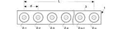
図1は、この発明の実施形態であるラインアレイスピーカユニットの構造を示す図である。このラインアレイスピーカユニット1は、細長いエンクロージャ(筐体)3に複数(n個)のスピーカ2(2−1〜2−n)をライン状に配列して構成されている。各スピーカ2の間隔dおよびスピーカアレイ(ライン状に配列されたスピーカ群)の長さLはビームコントロールするオーディオ周波数帯域に合わせて設定する。たとえば、高域をコントロールする場合はスピーカ間隔dを短くし、低域をコントロールする場合にはエンクロージャを長くしてスピーカアレイの長さLが長くなるように配置する。 FIG. 1 is a diagram showing the structure of a line array speaker unit according to an embodiment of the present invention. The line
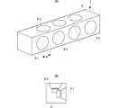
なお、より高域をコントロールしたい場合やスピーカの密度を増やして合成出力を大きくしたい場合には、図2に示すようにエンクロージャ3の2面にスピーカを交互に配列することによって、エンクロージャの正面の面積を大きくすることなく実質的にスピーカ間隔dを短くすることができる。2面のスピーカを互い違いになるように並べることにより、スピーカ間隔dをスピーカの直径よりも小さくすることができるので、1列の場合よりも高域をより良くコントロールすることができるとともに、より出力も大きくすることができる。 If you want to control higher frequencies or increase the density of the speakers to increase the combined output, you can arrange the speakers alternately on the two surfaces of the
なお、各スピーカは、一般的にはコーン型スピーカが用いられるが、指向性をつけることでパネル前方への音の放射効率を高くすることがより期待できるホーン型スピーカを用いてもよい。また、形式・性能の異なる複数種類のスピーカを混用してもよい。 Each speaker is generally a cone type speaker, but a horn type speaker that can be expected to increase the radiation efficiency of sound toward the front of the panel by providing directivity may be used. A plurality of types of speakers having different formats and performances may be mixed.
図3は、同ラインアレイスピーカユニットで形成されるビームの形状を示す図である。ライン状に配列されたスピーカアレイの各スピーカ2−1〜2−nに対して同じオーディオ信号を適当な位相差で入力すると、スピーカアレイを含む平面上では、同図(A)に示すように、波面がビーム状に絞り込まれて特定の方向のみに伝搬する。また、複数のオーディオ信号をそれぞれ別々の方向にビーム制御して合成して各スピーカに入力すれば、それぞれのオーディオ信号が前記別々の方向のビームとして出力される。 FIG. 3 is a diagram showing the shape of a beam formed by the line array speaker unit. When the same audio signal is input with an appropriate phase difference to each of the speakers 2-1 to 2-n of the speaker array arranged in a line, on the plane including the speaker array, as shown in FIG. The wavefront is narrowed down into a beam and propagates only in a specific direction. Also, if a plurality of audio signals are beam-controlled in different directions and combined and input to each speaker, the respective audio signals are output as beams in the different directions.
一方、同図(B)に示すように、スピーカ列に垂直な平面上では、オーディオ信号の指向性は制御されない。すなわち、各スピーカ2が元々有している指向性で伝搬する。 On the other hand, as shown in FIG. 5B, the directivity of the audio signal is not controlled on a plane perpendicular to the speaker array. That is, it propagates with the directivity that each
したがって、ライン状のスピーカアレイでオーディオ信号のビームをコントロールすることにより、スピーカアレイに垂直な方向に広がる扇形のビームをスピーカアレイの軸方向に角度制御して形成することができる。 Therefore, by controlling the audio signal beam with a linear speaker array, a fan-shaped beam extending in a direction perpendicular to the speaker array can be formed by controlling the angle in the axial direction of the speaker array.
このようなビームを形成することができるラインアレイスピーカユニットを用いて、聴取者の背面に虚像音源(ファントム)を形成するための制御方式およびオーディオシステムについて説明する。 A control system and an audio system for forming a virtual image sound source (phantom) on the back surface of a listener using a line array speaker unit capable of forming such a beam will be described.
ファントムとは、2チャンネルステレオの音像定位の原理を用いて形成された音像(音源)の虚像のことであり、右耳から聴取した音と左耳から聴取した音の時間差・音量差に基づき、聴取者がその中間の位置に音像を感じる現象をいう。 A phantom is a virtual image of a sound image (sound source) formed using the principle of sound image localization in 2-channel stereo. Based on the time difference and volume difference between the sound heard from the right ear and the sound heard from the left ear, A phenomenon in which a listener feels a sound image at an intermediate position.
一方、上述の非特許文献1、2に開示されているように、アレイスピーカを用いれば、ビームの焦点を部屋の壁面に結ばせて、壁面に仮想音源を形成することができる。非特許文献1、2に示しているようなマトリクスアレイのスピーカシステムであれば、鋭く絞り込まれたビームを形成することができるため、壁面に形成された仮想音源をそのままサラウンド音源として用いることができるが、この発明のラインアレイスピーカユニットの場合、上述したようにビームの絞り込みが扇形でブロードであるため、これによって形成された仮想音源をそのままサラウンド音源として用いることは困難である。 On the other hand, as disclosed in
そこで、この実施形態では、同じチャンネルのオーディオ信号を複数方向にビーム形成して複数のブロードな仮想音源を形成し、聴取者の左右の耳でこの複数の仮想音源から到来するオーディオ信号を聴取させることにより、所定の位置にファントムが形成されるように制御する。そして、このファントムをサランウド音源として用いる。 Therefore, in this embodiment, a plurality of broad virtual sound sources are formed by beam-forming audio signals of the same channel in a plurality of directions, and audio signals coming from the plurality of virtual sound sources are heard by the listener's left and right ears. Thus, control is performed so that the phantom is formed at a predetermined position. Then, this phantom is used as a Saran sound source.
なお、1つのラインアレイスピーカユニットで同じチャンネルの複数のビームを形成するようにしてもよいが、図4のように方向を変えて複数のラインアレイスピーカユニットを組み合わせ各ラインアレイスピーカユニットが別々の方向にビームを形成するようにしてもよい。このように複数のラインアレイスピーカユニットを方向を変えて複数組み合わせることにより、より明瞭なファントムを形成することができる。
図4において、同図(A)は2本のラインアレイスピーカユニットをT形に組み合わせた例である。同図(B)は2本のラインアレイスピーカユニットをL形に組み合わせた例である。同図(C)は3本のラインアレイスピーカユニットを左右および上に逆U形に組み合わせた例である。同図(D)は4本のラインアレイスピーカユニットをロ形に組み合わせた例である。同図(E)は2本のラインアレイスピーカユニットをX形に組み合わせた例である。A single line array speaker unit may form a plurality of beams of the same channel. However, as shown in FIG. 4, a plurality of line array speaker units are combined in different directions as shown in FIG. A beam may be formed in the direction. Thus, a clearer phantom can be formed by combining a plurality of line array speaker units by changing the direction.
In FIG. 4, FIG. 4A shows an example in which two line array speaker units are combined in a T shape. FIG. 5B shows an example in which two line array speaker units are combined in an L shape. FIG. 6C shows an example in which three line array speaker units are combined in an inverted U shape on the left and right and above. FIG. 4D shows an example in which four line array speaker units are combined in a square shape. FIG. 4E shows an example in which two line array speaker units are combined in an X shape.
このうち、(B)、(C)、(D)は、ディスプレイ5と組み合わせた例を示している。これらの例において、ディスプレイとスピーカとは一体型であってもよく、別々の筐体のものを組み合わせてもよい。 Among these, (B), (C), and (D) show examples combined with the display 5. In these examples, the display and the speaker may be integrated, or may be combined from different cases.
同図(B)の配置は、左右対称ではないが、縦置きスピーカからのビームは水平面に広がるため音は非対称とはならない。 The arrangement of FIG. 5B is not symmetrical, but the sound from the vertical speaker is not asymmetric because the beam from the vertical speaker spreads in the horizontal plane.
また同図(C)の配置は、通常のサラウンドシステムのフロント側スピーカと同様の配置であり、視覚的な違和感が少ないうえ、この配置であれば、5.1チャンネルサラウンドオーディオの全チャンネルをビームコントロールして仮想音源を設定する以外にも、サラウンドCHのみビームコントロールし、フロントのL,R,Cチャンネルは3つのラインアレイスピーカユニットを用いて通常に各チャンネル別に出力することもできる。この場合、リアのサラウンドチャンネルのみ仮想音源またはファントムを設定することになる。 In addition, the arrangement shown in FIG. 5C is the same arrangement as that of a front speaker of a normal surround system, and there is little visual discomfort. In this arrangement, all the channels of 5.1 channel surround audio are beamed. In addition to setting the virtual sound source by controlling, only the surround CH beam is controlled, and the front L, R, and C channels can be normally output for each channel using three line array speaker units. In this case, a virtual sound source or phantom is set only for the rear surround channel.
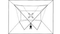
また、同図(E)の構成は、2つのラインアレイスピーカユニットをX字形に交差させて斜めに設置している。この配置の利点は縦横方向の配置ではできない斜め方向にビームをコントロールできることである。斜め方向は聴取位置からビームまでの距離が最も大きく取れるビーム経路であり、聴取者への音の被りが少ないため、他の配置形式と比較して直接/間接音比率を改善することができる。 In the configuration of FIG. 5E, two line array speaker units are installed obliquely so as to intersect each other in an X shape. The advantage of this arrangement is that the beam can be controlled in an oblique direction that cannot be achieved with the vertical and horizontal arrangements. The oblique direction is a beam path in which the distance from the listening position to the beam is the largest, and since there is little sound covering to the listener, the direct / indirect sound ratio can be improved as compared with other arrangement types.
図5、図6,図7は、それぞれ縦、横、斜めに設置したラインアレイスピーカユニットが形成するビームの軌跡/反射の様子を示す図である。
図5は、水平方向に設置されたラインアレイスピーカユニットが形成するビームを示す図である。水平方向に設置されたラインアレイスピーカユニットからは、水平方向の開角が絞り込まれ方向制御されたビームが形成される。ビーム形状は、上下方向にブロードな扇形となる。この水平設置では、側壁および後壁に焦点を結ぶビームを形成することができる。5, FIG. 6, and FIG. 7 are diagrams showing beam trajectories / reflection states formed by line array speaker units installed vertically, horizontally, and obliquely, respectively.
FIG. 5 is a diagram showing beams formed by line array speaker units installed in the horizontal direction. From the line array speaker unit installed in the horizontal direction, a beam whose direction is controlled by narrowing the opening angle in the horizontal direction is formed. The beam shape is a broad fan shape in the vertical direction. In this horizontal installation, a beam focused on the side wall and the rear wall can be formed.
図6は、垂直方向に設置されたラインアレイスピーカユニットが形成するビームを示す図である。垂直方向に設置されたラインアレイスピーカユニットからは、垂直方向の開角が絞り込まれ方向制御されたビームが形成される。ビーム形状は、水平方向にブロードな扇形となる。この垂直設置では、天井および後壁に焦点を結ぶビームを形成することができる。 FIG. 6 is a diagram showing a beam formed by a line array speaker unit installed in the vertical direction. A line array speaker unit installed in the vertical direction forms a beam whose aperture angle in the vertical direction is narrowed and whose direction is controlled. The beam shape is a broad fan shape in the horizontal direction. In this vertical installation, a beam focused on the ceiling and the rear wall can be formed.
図7は、斜め方向に設置されたラインアレイスピーカユニットが形成するビームを示す図である。斜め方向に設置されたラインアレイスピーカユニットからは、その設置方向に垂直な方向の開角が絞り込まれ、設置方向にはブロードな斜めのビームが形成される。すなわち、同図において、右上から左下に向けて設置されたラインアレイスピーカユニットの場合、右上から左下方向の開角が絞り込まれ、左上から右下方向がブロードなビーム形状となる。このビームで天井の右上角および後壁に焦点を結ばせることができる。 FIG. 7 is a diagram showing a beam formed by a line array speaker unit installed in an oblique direction. From the line array speaker unit installed in the oblique direction, the opening angle in the direction perpendicular to the installation direction is narrowed down, and a broad oblique beam is formed in the installation direction. That is, in the figure, in the case of the line array speaker unit installed from the upper right to the lower left, the opening angle from the upper right to the lower left is narrowed down, and the beam shape is broad from the upper left to the lower right. This beam can focus on the upper right corner of the ceiling and the rear wall.
上記のようにラインアレイスピーカユニットで形成したビームは扇形でブロードであるため、焦点が明瞭でないが、先行音効果(ハース効果)により聴取者に最初に音が到達する方向の壁面に仮想音源を想定することが可能である。ここで、先行音効果とは、広い範囲から同じ音が到来した場合、聴取者はその範囲のうち、最初に音が到来した方向に定位を感じるという音響心理学的性質である。したがって、聴取者に最初に音が到来する方向の壁面(天井面)に仮想音源を想定し、このようにして想定した複数の仮想音源に基づいてファントムを形成するようにすればよい。 Since the beam formed by the line array speaker unit is fan-shaped and broad as described above, the focal point is not clear, but the virtual sound source is placed on the wall surface in the direction in which the sound first reaches the listener due to the preceding sound effect (Haas effect). It is possible to assume. Here, the preceding sound effect is an acoustic psychological property that, when the same sound arrives from a wide range, the listener feels localization in the direction in which the sound first arrives. Therefore, a virtual sound source may be assumed on the wall surface (ceiling surface) in the direction in which sound first arrives at the listener, and a phantom may be formed based on the plurality of virtual sound sources thus assumed.
なお、ラインアレイスピーカユニットによると、上記のように定位がブロードになるため、実際にサラウンドスピーカを設置した場合にサラウンドの定位がはっきりしすぎる不自然さを軽減し、自然なサラウンド再生を実現することもできる。 In addition, according to the line array speaker unit, since the localization is broad as described above, when the surround speaker is actually installed, the unnaturalness that the localization of the surround is too clear is reduced, and natural surround reproduction is realized. You can also.
図8,図9は、ラインアレイスピーカユニットによるビーム形成により、複数の仮想音源を形成し、この複数の仮想音源によってファントムを形成する手順説明する図である。 8 and 9 are diagrams illustrating a procedure for forming a plurality of virtual sound sources by forming a beam using the line array speaker unit and forming a phantom using the plurality of virtual sound sources.
図8において、ビーム(1),(2)は横置きのラインアレイスピーカユニットからのビームを表し、ビーム(3),(4)は縦置きのラインアレイスピーカユニットからのビームを表している。ビーム(1),(3)で同一オーディオソース(チャンネル)を再生した場合、それらの音量バランスを調節することで、横壁と天井面にある仮想音源を結ぶ直線上、すなわち聴取者の斜め前方にファントムを作り出すことができる。同様にビーム(1),(2)で側方、ビーム(2),(4)で斜め後方などのように、1つのオーディオソースに対して複数のビームを組み合わせ、それぞれの音量を調整することで、自由な位置にファントムを定位させることが可能である。 In FIG. 8, beams (1) and (2) represent beams from the horizontal line array speaker unit, and beams (3) and (4) represent beams from the vertical line array speaker unit. When the same audio source (channel) is played with beams (1) and (3), the volume balance is adjusted so that the straight line connecting the horizontal sound source and the virtual sound source on the ceiling surface, that is, diagonally forward of the listener Can create phantoms. Similarly, combine multiple beams for one audio source, such as the side with beams (1) and (2) and the diagonally back with beams (2) and (4), and adjust the volume of each beam. Thus, it is possible to localize the phantom at a free position.
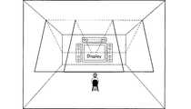
図9(A)〜(D)は、それぞれセンタ、フロント、サイド、リアにファントムを定位させるためのビーム形成の例を示す図である。それぞれ壁面にブロードな仮想音源を複数(2つ)形成することにより、聴取者はそのほぼ中間位置にファントム定位を聴覚的に認識することができる。この定位位置は、各ビームの方向や音量レベルなどの要素を制御することによって、任意の位置に制御することが可能である。 FIGS. 9A to 9D are diagrams showing examples of beam formation for locating the phantom at the center, front, side, and rear, respectively. By forming a plurality (two) of broad virtual sound sources on the respective wall surfaces, the listener can audibly recognize the phantom localization at an almost intermediate position. This localization position can be controlled to an arbitrary position by controlling factors such as the direction and volume level of each beam.
次に、上記ラインアレイスピーカユニットを用いてファントム定位機能を実現するオーディオ再生装置について説明する。 Next, an audio playback apparatus that realizes a phantom localization function using the line array speaker unit will be described.
図10は、同オーディオ再生装置の構成を示す図である。このオーディオ再生装置は、オーディオソースをデコードするデコーダ10、各チャンネルのファントム定位を制御する定位制御部11、この定位を実現するべく各チャンネルのオーディオソースのビーム方向・レベルを制御するビーム制御部12、および、ラインアレイスピーカユニットの各スピーカを駆動するためのオーディオ回路部13からなっている。スピーカシステムを複数のラインアレイスピーカユニットを(図4のように)組み合わせて構成する場合、ビーム制御部12およびオーディオ回路部13は、各ラインアレイスピーカユニットに対応してそれぞれ複数設けられる。 FIG. 10 is a diagram showing the configuration of the audio playback apparatus. This audio reproduction apparatus includes a decoder 10 that decodes an audio source, a
入力されるオーディオソースは、たとえば5.1チャンネルサラウンドのデジタル信号である。デコーダ10がこの信号を各チャンネルのデジタルオーディオ信号に分離する。このデジタルオーディオ信号はビーム制御部12に入力される。ビーム制御部12はDSPで構成すればよい。 The input audio source is, for example, a 5.1 channel surround digital signal. The decoder 10 separates this signal into digital audio signals for each channel. This digital audio signal is input to the
定位制御部11は、マイクロコンピュータ等で構成されており、各チャンネルのオーディオ信号をどの位置にファントム定位させるか、そのファントム定位のためにどの位置に仮想音源を設定するか、その仮想音源の設定のためにどの方向にビームを制御するか、および、このビーム形成のために各スピーカに入力するオーディオ信号のゲインおよびディレイをどのように設定するかを決定してビーム制御部に通知する。 The
図11はビーム制御部12の機能構成を示す図である。ビーム制御部12には、5.1チャンネル分のビーム制御ユニット12−1〜12−6が設けられている。各ビーム制御ユニットには、ディレイ120、および、ラインアレイスピーカユニットの各スピーカに対応するn個の係数乗算部121、122が設けられている。ディレイ120のタップ位置および係数乗算部121、122の係数は、定位制御部11から入力される。ディレイ120のタップ位置により、ビーム角度が決定される。係数乗算部121には、ディレイによる各スピーカの音量のずれをキャンセルしてビームのバランスを維持するための係数が入力される。また、係数乗算部122には、ビームのサイドローブをキャンセルするための窓関数が入力される。窓関数としては、ハミング窓またはハニング窓を用いればよい。 FIG. 11 is a diagram showing a functional configuration of the
各チャンネルのビーム制御ユニットの出力は、加算機123により、各スピーカ毎に加算され、オーディオ回路部13に出力される。 The output of the beam control unit of each channel is added for each speaker by the
図10において、オーディオ回路部13は、ラインアレイスピーカユニットの各スピーカに対応する数のD/Aコンバータ130およびオーディオアンプ131を備えている。D/Aコンバータ130には、ビーム制御部12からスピーカユニットに出力するデジタルオーディオ信号が入力される。このデジタルオーディオ信号は、図11で説明したように、各チャンネルのオーディオ信号を加算したものである。D/Aコンバータ130は、このデジタルオーディオ信号をアナログオーディオ信号に変換しオーディオアンプ131に入力する。オーディオアンプ131で増幅された信号は、ラインアレイスピーカユニット1の各スピーカに入力され、音響として出力される。 In FIG. 10, the
1…ラインアレイスピーカユニット
2(2−1〜2−n)…スピーカ
3…エンクロージャ(筐体)
10…デコーダ
11…定位制御部
12…ビーム制御部
12−1〜12−6…ビーム制御ユニット
13…オーディオ回路部
120…ディレイ
121,122…係数乗算部
130…D/Aコンバータ
131…オーディオアンプDESCRIPTION OF
DESCRIPTION OF SYMBOLS 10 ...
Claims (4)
Translated fromJapanese前記スピーカシステムの各スピーカに、同一のオーディオ信号をそれぞれ所定の遅延で供給することにより、前記オーディオ信号のビームを複数形成するオーディオ出力手段と、
前記複数のビームによって形成された複数の仮想音像が、所定位置に前記オーディオ信号の虚像音源を形成するよう、前記ビーム方向またはビーム強度を制御する定位制御手段と、
を備えたオーディオ再生装置。A speaker system comprising a plurality of speakers;
Audio output means for forming a plurality of beams of the audio signal by supplying the same audio signal to each speaker of the speaker system with a predetermined delay, respectively,
Localization control means for controlling the beam direction or beam intensity so that a plurality of virtual sound images formed by the plurality of beams form a virtual image sound source of the audio signal at a predetermined position;
An audio playback device comprising:
この複数のビームによって形成された複数の仮想音像が、所定位置に前記オーディオ信号の虚像音源を形成するよう、前記ビーム方向またはビーム強度を制御するオーディオ再生方法。A plurality of beams of the audio signal are formed by supplying the same audio signal with a predetermined delay to each speaker of the speaker system including a plurality of speakers,
An audio reproduction method for controlling the beam direction or beam intensity so that a plurality of virtual sound images formed by the plurality of beams form a virtual image sound source of the audio signal at a predetermined position.
Priority Applications (6)
| Application Number | Priority Date | Filing Date | Title |
|---|---|---|---|
| JP2003290686AJP4127156B2 (en) | 2003-08-08 | 2003-08-08 | Audio playback device, line array speaker unit, and audio playback method |
| CN2004800226869ACN101288338B (en) | 2003-08-08 | 2004-08-06 | Voice reproducing method and reproducer using line array speaker unit |
| EP04771642.8AEP1662842B1 (en) | 2003-08-08 | 2004-08-06 | Audio playback apparatus and method of operating thereof |
| PCT/JP2004/011675WO2005015956A1 (en) | 2003-08-08 | 2004-08-06 | Voice reproducing method and reproducer using line array speaker unit |
| EP19164488.9AEP3525485A1 (en) | 2003-08-08 | 2004-08-06 | Audio playback method and apparatus using line array speaker unit |
| US11/348,555US8345883B2 (en) | 2003-08-08 | 2006-02-06 | Audio playback method and apparatus using line array speaker unit |
Applications Claiming Priority (1)
| Application Number | Priority Date | Filing Date | Title |
|---|---|---|---|
| JP2003290686AJP4127156B2 (en) | 2003-08-08 | 2003-08-08 | Audio playback device, line array speaker unit, and audio playback method |
Publications (2)
| Publication Number | Publication Date |
|---|---|
| JP2005064746Atrue JP2005064746A (en) | 2005-03-10 |
| JP4127156B2 JP4127156B2 (en) | 2008-07-30 |
Family
ID=34131595
Family Applications (1)
| Application Number | Title | Priority Date | Filing Date |
|---|---|---|---|
| JP2003290686AExpired - Fee RelatedJP4127156B2 (en) | 2003-08-08 | 2003-08-08 | Audio playback device, line array speaker unit, and audio playback method |
Country Status (5)
| Country | Link |
|---|---|
| US (1) | US8345883B2 (en) |
| EP (2) | EP1662842B1 (en) |
| JP (1) | JP4127156B2 (en) |
| CN (1) | CN101288338B (en) |
| WO (1) | WO2005015956A1 (en) |
Cited By (24)
| Publication number | Priority date | Publication date | Assignee | Title |
|---|---|---|---|---|
| WO2006001272A1 (en)* | 2004-06-23 | 2006-01-05 | Yamaha Corporation | Loudspeaker array device and method for setting sound beam of loudspeaker array device |
| WO2006004159A1 (en)* | 2004-07-07 | 2006-01-12 | Yamaha Corporation | Loudspeaker directivity control method and audio reproduction device |
| US20060151237A1 (en)* | 2000-01-06 | 2006-07-13 | Iroquois Holding Company | Speaker system |
| JP2006295808A (en)* | 2005-04-14 | 2006-10-26 | Yamaha Corp | Audio signal supplying apparatus |
| JP2006334152A (en)* | 2005-06-02 | 2006-12-14 | Yamaha Corp | Game parlor conversational system |
| JP2007006073A (en)* | 2005-06-23 | 2007-01-11 | Yamaha Corp | Speaker system |
| WO2007007446A1 (en)* | 2005-07-14 | 2007-01-18 | Yamaha Corporation | Array speaker system and array microphone system |
| WO2007007684A1 (en)* | 2005-07-08 | 2007-01-18 | Yamaha Corporation | Audio device |
| JP2007028085A (en)* | 2005-07-14 | 2007-02-01 | Yamaha Corp | Array speaker system and line array unit |
| JP2007124140A (en)* | 2005-10-26 | 2007-05-17 | Yamaha Corp | Photographing device and communication conference system |
| JP2007259088A (en)* | 2006-03-23 | 2007-10-04 | Yamaha Corp | Speaker device and audio system |
| JP2009232438A (en)* | 2008-03-20 | 2009-10-08 | Weistech Technology Co Ltd | Vertically or horizontally placeable combinative array speaker |
| WO2009154067A1 (en)* | 2008-06-16 | 2009-12-23 | 株式会社 Trigence Semiconductor | Digital speaker driving device |
| JP2010011271A (en)* | 2008-06-30 | 2010-01-14 | Yamaha Corp | Speaker array unit |
| US8295516B2 (en) | 2006-10-23 | 2012-10-23 | Sony Corporation | System, apparatus, method and program for controlling output |
| WO2013002401A1 (en)* | 2011-06-30 | 2013-01-03 | ヤマハ株式会社 | Speaker array apparatus |
| JP2013048317A (en)* | 2011-08-29 | 2013-03-07 | Nippon Hoso Kyokai <Nhk> | Sound image localization device and program thereof |
| JP2013536630A (en)* | 2010-07-26 | 2013-09-19 | クゥアルコム・インコーポレイテッド | System, method and apparatus for enhanced generation of acoustic images in space |
| JP2014514856A (en)* | 2011-04-14 | 2014-06-19 | ボーズ・コーポレーション | Acoustic driver operation according to orientation |
| JP2015043618A (en)* | 2014-10-29 | 2015-03-05 | ヤマハ株式会社 | Speaker array system |
| US9154876B2 (en) | 2009-10-20 | 2015-10-06 | Samsung Electronics Co., Ltd. | Apparatus and method for generating an acoustic radiation pattern |
| JP2015531218A (en)* | 2012-08-31 | 2015-10-29 | ドルビー ラボラトリーズ ライセンシング コーポレイション | Virtual rendering of object-based audio |
| JP2018527808A (en)* | 2015-08-03 | 2018-09-20 | フラウンホーファー−ゲゼルシャフト・ツール・フェルデルング・デル・アンゲヴァンテン・フォルシュング・アインゲトラーゲネル・フェライン | Sound bar |
| WO2025154954A1 (en)* | 2024-01-19 | 2025-07-24 | 삼성전자주식회사 | Electronic device and method of controlling same |
Families Citing this family (115)
| Publication number | Priority date | Publication date | Assignee | Title |
|---|---|---|---|---|
| JP2005197896A (en) | 2004-01-05 | 2005-07-21 | Yamaha Corp | Audio signal supply apparatus for speaker array |
| JP4251077B2 (en) | 2004-01-07 | 2009-04-08 | ヤマハ株式会社 | Speaker device |
| JP3915804B2 (en) | 2004-08-26 | 2007-05-16 | ヤマハ株式会社 | Audio playback device |
| US8880205B2 (en)* | 2004-12-30 | 2014-11-04 | Mondo Systems, Inc. | Integrated multimedia signal processing system using centralized processing of signals |
| US7653447B2 (en)* | 2004-12-30 | 2010-01-26 | Mondo Systems, Inc. | Integrated audio video signal processing system using centralized processing of signals |
| US8015590B2 (en)* | 2004-12-30 | 2011-09-06 | Mondo Systems, Inc. | Integrated multimedia signal processing system using centralized processing of signals |
| JP4779381B2 (en) | 2005-02-25 | 2011-09-28 | ヤマハ株式会社 | Array speaker device |
| JP4107300B2 (en)* | 2005-03-10 | 2008-06-25 | ヤマハ株式会社 | Surround system |
| JP2006262416A (en)* | 2005-03-18 | 2006-09-28 | Yamaha Corp | Acoustic system, method of controlling acoustic system, and acoustic apparatus |
| US20060251271A1 (en)* | 2005-05-04 | 2006-11-09 | Anthony Grimani | Ceiling Mounted Loudspeaker System |
| JP2006340057A (en)* | 2005-06-02 | 2006-12-14 | Yamaha Corp | Array speaker system |
| JP4103903B2 (en)* | 2005-06-06 | 2008-06-18 | ヤマハ株式会社 | Audio apparatus and beam control method using audio apparatus |
| GB0514361D0 (en)* | 2005-07-12 | 2005-08-17 | 1 Ltd | Compact surround sound effects system |
| CN101496387B (en) | 2006-03-06 | 2012-09-05 | 思科技术公司 | System and method for access authentication in a mobile wireless network |
| US7679639B2 (en)* | 2006-04-20 | 2010-03-16 | Cisco Technology, Inc. | System and method for enhancing eye gaze in a telepresence system |
| US7692680B2 (en)* | 2006-04-20 | 2010-04-06 | Cisco Technology, Inc. | System and method for providing location specific sound in a telepresence system |
| US8180067B2 (en)* | 2006-04-28 | 2012-05-15 | Harman International Industries, Incorporated | System for selectively extracting components of an audio input signal |
| USD610105S1 (en) | 2006-07-10 | 2010-02-16 | Cisco Technology, Inc. | Telepresence system |
| US8036767B2 (en)* | 2006-09-20 | 2011-10-11 | Harman International Industries, Incorporated | System for extracting and changing the reverberant content of an audio input signal |
| WO2008115284A2 (en) | 2006-10-16 | 2008-09-25 | Thx Ltd. | Loudspeaker line array configurations and related sound processing |
| US20100027806A1 (en)* | 2006-12-14 | 2010-02-04 | Cambridge Sound Management, Llc | Distributed emitter voice lift system |
| KR101297300B1 (en)* | 2007-01-31 | 2013-08-16 | 삼성전자주식회사 | Front Surround system and method for processing signal using speaker array |
| JP4449998B2 (en)* | 2007-03-12 | 2010-04-14 | ヤマハ株式会社 | Array speaker device |
| JP4561785B2 (en)* | 2007-07-03 | 2010-10-13 | ヤマハ株式会社 | Speaker array device |
| JP4488036B2 (en)* | 2007-07-23 | 2010-06-23 | ヤマハ株式会社 | Speaker array device |
| US20090103753A1 (en)* | 2007-10-19 | 2009-04-23 | Weistech Technology Co., Ltd | Three-dimension array structure of surround-sound speaker |
| US8797377B2 (en) | 2008-02-14 | 2014-08-05 | Cisco Technology, Inc. | Method and system for videoconference configuration |
| US8355041B2 (en) | 2008-02-14 | 2013-01-15 | Cisco Technology, Inc. | Telepresence system for 360 degree video conferencing |
| US8319819B2 (en) | 2008-03-26 | 2012-11-27 | Cisco Technology, Inc. | Virtual round-table videoconference |
| US8390667B2 (en) | 2008-04-15 | 2013-03-05 | Cisco Technology, Inc. | Pop-up PIP for people not in picture |
| US8620009B2 (en)* | 2008-06-17 | 2013-12-31 | Microsoft Corporation | Virtual sound source positioning |
| US8274611B2 (en)* | 2008-06-27 | 2012-09-25 | Mitsubishi Electric Visual Solutions America, Inc. | System and methods for television with integrated sound projection system |
| US8279357B2 (en)* | 2008-09-02 | 2012-10-02 | Mitsubishi Electric Visual Solutions America, Inc. | System and methods for television with integrated sound projection system |
| US8694658B2 (en) | 2008-09-19 | 2014-04-08 | Cisco Technology, Inc. | System and method for enabling communication sessions in a network environment |
| KR101298487B1 (en)* | 2008-12-10 | 2013-08-22 | 삼성전자주식회사 | Directional sound generating apparatus and method |
| JP5577597B2 (en)* | 2009-01-28 | 2014-08-27 | ヤマハ株式会社 | Speaker array device, signal processing method and program |
| US8659637B2 (en) | 2009-03-09 | 2014-02-25 | Cisco Technology, Inc. | System and method for providing three dimensional video conferencing in a network environment |
| US8477175B2 (en)* | 2009-03-09 | 2013-07-02 | Cisco Technology, Inc. | System and method for providing three dimensional imaging in a network environment |
| US8659639B2 (en) | 2009-05-29 | 2014-02-25 | Cisco Technology, Inc. | System and method for extending communications between participants in a conferencing environment |
| US9082297B2 (en) | 2009-08-11 | 2015-07-14 | Cisco Technology, Inc. | System and method for verifying parameters in an audiovisual environment |
| US9372251B2 (en)* | 2009-10-05 | 2016-06-21 | Harman International Industries, Incorporated | System for spatial extraction of audio signals |
| CN101720052B (en)* | 2009-11-30 | 2012-12-26 | 广州市迪士普音响科技有限公司 | Speaker system with three-dimensional adjustable voice directions |
| US9225916B2 (en) | 2010-03-18 | 2015-12-29 | Cisco Technology, Inc. | System and method for enhancing video images in a conferencing environment |
| USD626102S1 (en) | 2010-03-21 | 2010-10-26 | Cisco Tech Inc | Video unit with integrated features |
| USD626103S1 (en) | 2010-03-21 | 2010-10-26 | Cisco Technology, Inc. | Video unit with integrated features |
| CN102223589A (en)* | 2010-04-14 | 2011-10-19 | 北京富纳特创新科技有限公司 | Sound projector |
| CN102223588A (en) | 2010-04-14 | 2011-10-19 | 北京富纳特创新科技有限公司 | Sound projector |
| US9313452B2 (en) | 2010-05-17 | 2016-04-12 | Cisco Technology, Inc. | System and method for providing retracting optics in a video conferencing environment |
| US20120038827A1 (en)* | 2010-08-11 | 2012-02-16 | Charles Davis | System and methods for dual view viewing with targeted sound projection |
| US8896655B2 (en) | 2010-08-31 | 2014-11-25 | Cisco Technology, Inc. | System and method for providing depth adaptive video conferencing |
| WO2012032335A1 (en)* | 2010-09-06 | 2012-03-15 | Cambridge Mechatronics Limited | Array loudspeaker system |
| US8599934B2 (en) | 2010-09-08 | 2013-12-03 | Cisco Technology, Inc. | System and method for skip coding during video conferencing in a network environment |
| JP5141738B2 (en)* | 2010-09-17 | 2013-02-13 | 株式会社デンソー | 3D sound field generator |
| US8599865B2 (en) | 2010-10-26 | 2013-12-03 | Cisco Technology, Inc. | System and method for provisioning flows in a mobile network environment |
| US8699457B2 (en) | 2010-11-03 | 2014-04-15 | Cisco Technology, Inc. | System and method for managing flows in a mobile network environment |
| JP5682244B2 (en) | 2010-11-09 | 2015-03-11 | ソニー株式会社 | Speaker system |
| US8730297B2 (en) | 2010-11-15 | 2014-05-20 | Cisco Technology, Inc. | System and method for providing camera functions in a video environment |
| US8902244B2 (en) | 2010-11-15 | 2014-12-02 | Cisco Technology, Inc. | System and method for providing enhanced graphics in a video environment |
| US9338394B2 (en) | 2010-11-15 | 2016-05-10 | Cisco Technology, Inc. | System and method for providing enhanced audio in a video environment |
| US9143725B2 (en) | 2010-11-15 | 2015-09-22 | Cisco Technology, Inc. | System and method for providing enhanced graphics in a video environment |
| US8542264B2 (en) | 2010-11-18 | 2013-09-24 | Cisco Technology, Inc. | System and method for managing optics in a video environment |
| US8723914B2 (en) | 2010-11-19 | 2014-05-13 | Cisco Technology, Inc. | System and method for providing enhanced video processing in a network environment |
| US9111138B2 (en) | 2010-11-30 | 2015-08-18 | Cisco Technology, Inc. | System and method for gesture interface control |
| USD678320S1 (en) | 2010-12-16 | 2013-03-19 | Cisco Technology, Inc. | Display screen with graphical user interface |
| USD682294S1 (en) | 2010-12-16 | 2013-05-14 | Cisco Technology, Inc. | Display screen with graphical user interface |
| USD682864S1 (en) | 2010-12-16 | 2013-05-21 | Cisco Technology, Inc. | Display screen with graphical user interface |
| USD682293S1 (en) | 2010-12-16 | 2013-05-14 | Cisco Technology, Inc. | Display screen with graphical user interface |
| USD682854S1 (en) | 2010-12-16 | 2013-05-21 | Cisco Technology, Inc. | Display screen for graphical user interface |
| USD678307S1 (en) | 2010-12-16 | 2013-03-19 | Cisco Technology, Inc. | Display screen with graphical user interface |
| USD678894S1 (en) | 2010-12-16 | 2013-03-26 | Cisco Technology, Inc. | Display screen with graphical user interface |
| USD678308S1 (en) | 2010-12-16 | 2013-03-19 | Cisco Technology, Inc. | Display screen with graphical user interface |
| KR101825462B1 (en)* | 2010-12-22 | 2018-03-22 | 삼성전자주식회사 | Method and apparatus for creating personal sound zone |
| US8692862B2 (en) | 2011-02-28 | 2014-04-08 | Cisco Technology, Inc. | System and method for selection of video data in a video conference environment |
| WO2012122115A2 (en)* | 2011-03-04 | 2012-09-13 | Wan Jin Chung | Line speaker system and layout |
| US8670019B2 (en) | 2011-04-28 | 2014-03-11 | Cisco Technology, Inc. | System and method for providing enhanced eye gaze in a video conferencing environment |
| US8786631B1 (en) | 2011-04-30 | 2014-07-22 | Cisco Technology, Inc. | System and method for transferring transparency information in a video environment |
| US8934026B2 (en) | 2011-05-12 | 2015-01-13 | Cisco Technology, Inc. | System and method for video coding in a dynamic environment |
| US8947493B2 (en) | 2011-11-16 | 2015-02-03 | Cisco Technology, Inc. | System and method for alerting a participant in a video conference |
| US8682087B2 (en) | 2011-12-19 | 2014-03-25 | Cisco Technology, Inc. | System and method for depth-guided image filtering in a video conference environment |
| KR101708522B1 (en) | 2012-05-31 | 2017-02-20 | 한국전자통신연구원 | Method and apparatus for processing the audio signal, audio playing system |
| CN107454511B (en)* | 2012-08-31 | 2024-04-05 | 杜比实验室特许公司 | Loudspeaker for reflecting sound from a viewing screen or display surface |
| US9681154B2 (en) | 2012-12-06 | 2017-06-13 | Patent Capital Group | System and method for depth-guided filtering in a video conference environment |
| US9843621B2 (en) | 2013-05-17 | 2017-12-12 | Cisco Technology, Inc. | Calendaring activities based on communication processing |
| DE102013013378A1 (en)* | 2013-08-10 | 2015-02-12 | Advanced Acoustic Sf Gmbh | Distribution of virtual sound sources |
| CN105453586A (en)* | 2013-08-30 | 2016-03-30 | 索尼公司 | Speaker device |
| US9560449B2 (en) | 2014-01-17 | 2017-01-31 | Sony Corporation | Distributed wireless speaker system |
| US9866986B2 (en) | 2014-01-24 | 2018-01-09 | Sony Corporation | Audio speaker system with virtual music performance |
| US9232335B2 (en) | 2014-03-06 | 2016-01-05 | Sony Corporation | Networked speaker system with follow me |
| US10679407B2 (en) | 2014-06-27 | 2020-06-09 | The University Of North Carolina At Chapel Hill | Methods, systems, and computer readable media for modeling interactive diffuse reflections and higher-order diffraction in virtual environment scenes |
| US9977644B2 (en)* | 2014-07-29 | 2018-05-22 | The University Of North Carolina At Chapel Hill | Methods, systems, and computer readable media for conducting interactive sound propagation and rendering for a plurality of sound sources in a virtual environment scene |
| WO2016033400A1 (en)* | 2014-08-29 | 2016-03-03 | Harman International Industries, Inc. | Wireless speaker system |
| US9762999B1 (en)* | 2014-09-30 | 2017-09-12 | Apple Inc. | Modal based architecture for controlling the directivity of loudspeaker arrays |
| CN113140216B (en)* | 2015-02-03 | 2023-09-19 | 杜比实验室特许公司 | Selective meeting abstract |
| JP6543957B2 (en)* | 2015-02-26 | 2019-07-17 | ヤマハ株式会社 | Speaker array device |
| WO2016182184A1 (en) | 2015-05-08 | 2016-11-17 | 삼성전자 주식회사 | Three-dimensional sound reproduction method and device |
| US10299064B2 (en) | 2015-06-10 | 2019-05-21 | Harman International Industries, Incorporated | Surround sound techniques for highly-directional speakers |
| KR102484981B1 (en)* | 2015-11-24 | 2023-01-05 | 엘지전자 주식회사 | Speaker module, electronic device and display device comprising it |
| CN108601450A (en) | 2015-11-25 | 2018-09-28 | 托马斯·米切尔·戴尔 | Surround sound applications and devices for vertically oriented content |
| EP3188504B1 (en)* | 2016-01-04 | 2020-07-29 | Harman Becker Automotive Systems GmbH | Multi-media reproduction for a multiplicity of recipients |
| JP6905824B2 (en) | 2016-01-04 | 2021-07-21 | ハーマン ベッカー オートモーティブ システムズ ゲーエムベーハー | Sound reproduction for a large number of listeners |
| US9693168B1 (en) | 2016-02-08 | 2017-06-27 | Sony Corporation | Ultrasonic speaker assembly for audio spatial effect |
| US9826332B2 (en) | 2016-02-09 | 2017-11-21 | Sony Corporation | Centralized wireless speaker system |
| US9924291B2 (en) | 2016-02-16 | 2018-03-20 | Sony Corporation | Distributed wireless speaker system |
| US9826330B2 (en)* | 2016-03-14 | 2017-11-21 | Sony Corporation | Gimbal-mounted linear ultrasonic speaker assembly |
| US9693169B1 (en) | 2016-03-16 | 2017-06-27 | Sony Corporation | Ultrasonic speaker assembly with ultrasonic room mapping |
| US9794724B1 (en) | 2016-07-20 | 2017-10-17 | Sony Corporation | Ultrasonic speaker assembly using variable carrier frequency to establish third dimension sound locating |
| US9854362B1 (en) | 2016-10-20 | 2017-12-26 | Sony Corporation | Networked speaker system with LED-based wireless communication and object detection |
| US9924286B1 (en) | 2016-10-20 | 2018-03-20 | Sony Corporation | Networked speaker system with LED-based wireless communication and personal identifier |
| US10075791B2 (en) | 2016-10-20 | 2018-09-11 | Sony Corporation | Networked speaker system with LED-based wireless communication and room mapping |
| US10248744B2 (en) | 2017-02-16 | 2019-04-02 | The University Of North Carolina At Chapel Hill | Methods, systems, and computer readable media for acoustic classification and optimization for multi-modal rendering of real-world scenes |
| US10531196B2 (en)* | 2017-06-02 | 2020-01-07 | Apple Inc. | Spatially ducking audio produced through a beamforming loudspeaker array |
| US10623859B1 (en) | 2018-10-23 | 2020-04-14 | Sony Corporation | Networked speaker system with combined power over Ethernet and audio delivery |
| JP7436673B2 (en) | 2019-12-20 | 2024-02-21 | ホアウェイ・テクノロジーズ・カンパニー・リミテッド | Audio device and method for generating three-dimensional sound field |
| US11443737B2 (en) | 2020-01-14 | 2022-09-13 | Sony Corporation | Audio video translation into multiple languages for respective listeners |
| US12058492B2 (en)* | 2022-05-12 | 2024-08-06 | Bose Corporation | Directional sound-producing device |
Family Cites Families (36)
| Publication number | Priority date | Publication date | Assignee | Title |
|---|---|---|---|---|
| CH667174A5 (en)* | 1986-06-05 | 1988-09-15 | Sound Electronic Systems | MONOLITHIC STEREOPHONIC SPEAKER. |
| JPH02224495A (en)* | 1989-02-27 | 1990-09-06 | Canon Inc | Screen for video display |
| JP2708105B2 (en) | 1989-04-26 | 1998-02-04 | 富士通テン 株式会社 | In-vehicle sound reproduction device |
| US5109416A (en)* | 1990-09-28 | 1992-04-28 | Croft James J | Dipole speaker for producing ambience sound |
| US5325435A (en)* | 1991-06-12 | 1994-06-28 | Matsushita Electric Industrial Co., Ltd. | Sound field offset device |
| DE4217495A1 (en)* | 1992-05-27 | 1993-12-02 | Hoechst Ag | Photopolymerizable mixture and recording material produced therefrom |
| JPH0635489A (en) | 1992-07-21 | 1994-02-10 | Mitsubishi Electric Corp | Speaker system for television |
| JPH06178379A (en) | 1992-12-10 | 1994-06-24 | Sony Corp | Video visuality system |
| JP3205625B2 (en)* | 1993-01-07 | 2001-09-04 | パイオニア株式会社 | Speaker device |
| JPH0787590A (en) | 1993-09-10 | 1995-03-31 | Matsushita Electric Ind Co Ltd | Directional control speaker device |
| EP0700620B1 (en) | 1994-03-24 | 2001-10-17 | Koninklijke Philips Electronics N.V. | Audio-visual arrangement and system in which such an arrangement is used |
| NL9401860A (en)* | 1994-11-08 | 1996-06-03 | Duran Bv | Loudspeaker system with controlled directivity. |
| US5809150A (en)* | 1995-06-28 | 1998-09-15 | Eberbach; Steven J. | Surround sound loudspeaker system |
| DE69637736D1 (en)* | 1995-09-08 | 2008-12-18 | Fujitsu Ltd | Three-dimensional acoustic processor with application of linear predictive coefficients |
| US6229899B1 (en)* | 1996-07-17 | 2001-05-08 | American Technology Corporation | Method and device for developing a virtual speaker distant from the sound source |
| JP3885976B2 (en)* | 1996-09-12 | 2007-02-28 | 富士通株式会社 | Computer, computer system and desktop theater system |
| US6343132B1 (en)* | 1997-02-28 | 2002-01-29 | Matsushita Electric Industrial Co., Ltd. | Loudspeaker |
| JP2002500844A (en) | 1997-05-28 | 2002-01-08 | バウク、ジェラルド、エル | Loudspeaker array for enlarged sweet spot |
| US6005947A (en)* | 1997-12-08 | 1999-12-21 | Lim; Yong Ching | Technique for enhancing stereo sound |
| TW411722B (en)* | 1998-01-08 | 2000-11-11 | Sanyo Electric Co | Pseudo-stereophonic device |
| JP3252803B2 (en) | 1998-07-21 | 2002-02-04 | 日本電気株式会社 | Super directional speaker device |
| DE60004009D1 (en)* | 1999-01-06 | 2003-08-28 | Iroquois Holding Co Inc | SPEAKER SYSTEM |
| WO2000059265A1 (en) | 1999-03-31 | 2000-10-05 | Qsound Labs, Inc. | Matrix surround decoder/virtualizer |
| CN100358393C (en) | 1999-09-29 | 2007-12-26 | 1...有限公司 | Method and apparatus for directing sound |
| JP2001128279A (en)* | 1999-10-27 | 2001-05-11 | Matsushita Electric Ind Co Ltd | Directional speaker device |
| AU2000226583A1 (en)* | 2000-02-18 | 2001-08-27 | Bang And Olufsen A/S | Multi-channel sound reproduction system for stereophonic signals |
| US7260235B1 (en)* | 2000-10-16 | 2007-08-21 | Bose Corporation | Line electroacoustical transducing |
| US20020131608A1 (en)* | 2001-03-01 | 2002-09-19 | William Lobb | Method and system for providing digitally focused sound |
| WO2002078388A2 (en)* | 2001-03-27 | 2002-10-03 | 1... Limited | Method and apparatus to create a sound field |
| GB0124352D0 (en)* | 2001-10-11 | 2001-11-28 | 1 Ltd | Signal processing device for acoustic transducer array |
| US7130430B2 (en)* | 2001-12-18 | 2006-10-31 | Milsap Jeffrey P | Phased array sound system |
| US7822496B2 (en)* | 2002-11-15 | 2010-10-26 | Sony Corporation | Audio signal processing method and apparatus |
| JP3982394B2 (en) | 2002-11-25 | 2007-09-26 | ソニー株式会社 | Speaker device and sound reproduction method |
| US7826622B2 (en)* | 2003-05-27 | 2010-11-02 | Harman International Industries, Incorporated | Constant-beamwidth loudspeaker array |
| JP3808069B2 (en)* | 2003-11-21 | 2006-08-09 | 株式会社沖データ | Fixing device and image forming apparatus |
| JP4254502B2 (en)* | 2003-11-21 | 2009-04-15 | ヤマハ株式会社 | Array speaker device |
- 2003
- 2003-08-08JPJP2003290686Apatent/JP4127156B2/ennot_activeExpired - Fee Related
- 2004
- 2004-08-06EPEP04771642.8Apatent/EP1662842B1/ennot_activeExpired - Lifetime
- 2004-08-06WOPCT/JP2004/011675patent/WO2005015956A1/enactiveApplication Filing
- 2004-08-06CNCN2004800226869Apatent/CN101288338B/ennot_activeExpired - Fee Related
- 2004-08-06EPEP19164488.9Apatent/EP3525485A1/ennot_activeWithdrawn
- 2006
- 2006-02-06USUS11/348,555patent/US8345883B2/enactiveActive
Cited By (42)
| Publication number | Priority date | Publication date | Assignee | Title |
|---|---|---|---|---|
| US20060151237A1 (en)* | 2000-01-06 | 2006-07-13 | Iroquois Holding Company | Speaker system |
| US8144900B2 (en)* | 2000-01-06 | 2012-03-27 | Oxford J Craig | Speaker system |
| US20110013778A1 (en)* | 2004-06-23 | 2011-01-20 | Yamaha Corporation | Speaker array apparatus and method for setting audio beams of speaker array appratus |
| US7889878B2 (en) | 2004-06-23 | 2011-02-15 | Yamaha Corporation | Speaker array apparatus and method for setting audio beams of speaker array apparatus |
| WO2006001272A1 (en)* | 2004-06-23 | 2006-01-05 | Yamaha Corporation | Loudspeaker array device and method for setting sound beam of loudspeaker array device |
| US8422704B2 (en) | 2004-06-23 | 2013-04-16 | Yamaha Corporation | Speaker array apparatus and method for setting audio beams of speaker array apparatus |
| US8315403B2 (en) | 2004-07-07 | 2012-11-20 | Yamaha Corporation | Method for controlling directivity of loudspeaker apparatus and audio reproduction apparatus |
| WO2006004159A1 (en)* | 2004-07-07 | 2006-01-12 | Yamaha Corporation | Loudspeaker directivity control method and audio reproduction device |
| JP2006295808A (en)* | 2005-04-14 | 2006-10-26 | Yamaha Corp | Audio signal supplying apparatus |
| US7885424B2 (en) | 2005-04-14 | 2011-02-08 | Yamaha Corporation | Audio signal supply apparatus |
| JP2006334152A (en)* | 2005-06-02 | 2006-12-14 | Yamaha Corp | Game parlor conversational system |
| JP2007006073A (en)* | 2005-06-23 | 2007-01-11 | Yamaha Corp | Speaker system |
| JP2007019938A (en)* | 2005-07-08 | 2007-01-25 | Yamaha Corp | Audio system |
| US8184836B2 (en) | 2005-07-08 | 2012-05-22 | Yamaha Corporation | Audio apparatus |
| WO2007007684A1 (en)* | 2005-07-08 | 2007-01-18 | Yamaha Corporation | Audio device |
| US8320596B2 (en) | 2005-07-14 | 2012-11-27 | Yamaha Corporation | Array speaker system and array microphone system |
| JP2007028085A (en)* | 2005-07-14 | 2007-02-01 | Yamaha Corp | Array speaker system and line array unit |
| WO2007007446A1 (en)* | 2005-07-14 | 2007-01-18 | Yamaha Corporation | Array speaker system and array microphone system |
| JP2007124140A (en)* | 2005-10-26 | 2007-05-17 | Yamaha Corp | Photographing device and communication conference system |
| JP2007259088A (en)* | 2006-03-23 | 2007-10-04 | Yamaha Corp | Speaker device and audio system |
| US8295516B2 (en) | 2006-10-23 | 2012-10-23 | Sony Corporation | System, apparatus, method and program for controlling output |
| JP2009232438A (en)* | 2008-03-20 | 2009-10-08 | Weistech Technology Co Ltd | Vertically or horizontally placeable combinative array speaker |
| US8306244B2 (en) | 2008-06-16 | 2012-11-06 | Trigence Semiconductor, Inc. | Digital speaker driving apparatus |
| WO2009154067A1 (en)* | 2008-06-16 | 2009-12-23 | 株式会社 Trigence Semiconductor | Digital speaker driving device |
| US9693136B2 (en) | 2008-06-16 | 2017-06-27 | Trigence Semiconductor Inc. | Digital speaker driving apparatus |
| US9226053B2 (en) | 2008-06-16 | 2015-12-29 | Trigence Semiconductor, Inc. | Digital speaker driving apparatus |
| CN101803401A (en)* | 2008-06-16 | 2010-08-11 | 株式会社特瑞君思半导体 | Digital Speaker Driver |
| JP2010011271A (en)* | 2008-06-30 | 2010-01-14 | Yamaha Corp | Speaker array unit |
| US9154876B2 (en) | 2009-10-20 | 2015-10-06 | Samsung Electronics Co., Ltd. | Apparatus and method for generating an acoustic radiation pattern |
| JP2013536630A (en)* | 2010-07-26 | 2013-09-19 | クゥアルコム・インコーポレイテッド | System, method and apparatus for enhanced generation of acoustic images in space |
| US8965546B2 (en) | 2010-07-26 | 2015-02-24 | Qualcomm Incorporated | Systems, methods, and apparatus for enhanced acoustic imaging |
| JP2014514856A (en)* | 2011-04-14 | 2014-06-19 | ボーズ・コーポレーション | Acoustic driver operation according to orientation |
| US9167369B2 (en) | 2011-06-30 | 2015-10-20 | Yamaha Corporation | Speaker array apparatus |
| US9560450B2 (en) | 2011-06-30 | 2017-01-31 | Yamaha Corporation | Speaker array apparatus |
| WO2013002401A1 (en)* | 2011-06-30 | 2013-01-03 | ヤマハ株式会社 | Speaker array apparatus |
| JP2013048317A (en)* | 2011-08-29 | 2013-03-07 | Nippon Hoso Kyokai <Nhk> | Sound image localization device and program thereof |
| JP2015531218A (en)* | 2012-08-31 | 2015-10-29 | ドルビー ラボラトリーズ ライセンシング コーポレイション | Virtual rendering of object-based audio |
| US9622011B2 (en) | 2012-08-31 | 2017-04-11 | Dolby Laboratories Licensing Corporation | Virtual rendering of object-based audio |
| JP2015043618A (en)* | 2014-10-29 | 2015-03-05 | ヤマハ株式会社 | Speaker array system |
| JP2018527808A (en)* | 2015-08-03 | 2018-09-20 | フラウンホーファー−ゲゼルシャフト・ツール・フェルデルング・デル・アンゲヴァンテン・フォルシュング・アインゲトラーゲネル・フェライン | Sound bar |
| US10863276B2 (en) | 2015-08-03 | 2020-12-08 | Fraunhofer-Gesellschaft Zur Foerderung Der Angewandten Forschung E.V. | Soundbar |
| WO2025154954A1 (en)* | 2024-01-19 | 2025-07-24 | 삼성전자주식회사 | Electronic device and method of controlling same |
Also Published As
| Publication number | Publication date |
|---|---|
| EP1662842A4 (en) | 2010-03-31 |
| WO2005015956A1 (en) | 2005-02-17 |
| US8345883B2 (en) | 2013-01-01 |
| CN101288338B (en) | 2010-09-15 |
| EP1662842A1 (en) | 2006-05-31 |
| JP4127156B2 (en) | 2008-07-30 |
| US20060126878A1 (en) | 2006-06-15 |
| EP1662842B1 (en) | 2019-06-19 |
| EP3525485A1 (en) | 2019-08-14 |
| CN101288338A (en) | 2008-10-15 |
Similar Documents
| Publication | Publication Date | Title |
|---|---|---|
| JP4127156B2 (en) | Audio playback device, line array speaker unit, and audio playback method | |
| US9031267B2 (en) | Loudspeaker array providing direct and indirect radiation from same set of drivers | |
| TWI477158B (en) | Speaker line array configuration and related sound processing | |
| US5764777A (en) | Four dimensional acoustical audio system | |
| EP2664165B1 (en) | Apparatus, systems and methods for controllable sound regions in a media room | |
| US8351639B2 (en) | Multi-directional sound emission system | |
| JP3826423B2 (en) | Speaker device | |
| US8351640B2 (en) | Multi-directional sound emission means and multi-directional sound emission system | |
| JP2006067218A (en) | Audio playback device | |
| JP2013016925A (en) | Speaker array system | |
| JP2006518956A (en) | Sound beam speaker system | |
| WO2005067348A1 (en) | Audio signal supplying apparatus for speaker array | |
| JP3982394B2 (en) | Speaker device and sound reproduction method | |
| JP2006303658A (en) | Reproducing device and reproducing method | |
| JP2007506323A (en) | Digital speaker | |
| US20060251271A1 (en) | Ceiling Mounted Loudspeaker System | |
| JP5215299B2 (en) | Speaker system having at least two speaker devices and one unit for processing audio content signals | |
| JP2004186895A (en) | Speaker device | |
| JP2006121125A (en) | Reproducing apparatus of audio signal and reproducing method thereof | |
| US20240223944A1 (en) | Loudspeaker System for Reflection-Based Imaging | |
| GB2256773A (en) | Loudspeaker uinit | |
| HK1013782A (en) | An acoustical audio system for producing three dimensional sound image |
Legal Events
| Date | Code | Title | Description |
|---|---|---|---|
| A621 | Written request for application examination | Free format text:JAPANESE INTERMEDIATE CODE: A621 Effective date:20050728 | |
| A131 | Notification of reasons for refusal | Free format text:JAPANESE INTERMEDIATE CODE: A131 Effective date:20061205 | |
| A521 | Request for written amendment filed | Free format text:JAPANESE INTERMEDIATE CODE: A523 Effective date:20070205 | |
| TRDD | Decision of grant or rejection written | ||
| A01 | Written decision to grant a patent or to grant a registration (utility model) | Free format text:JAPANESE INTERMEDIATE CODE: A01 Effective date:20080422 | |
| A01 | Written decision to grant a patent or to grant a registration (utility model) | Free format text:JAPANESE INTERMEDIATE CODE: A01 | |
| A61 | First payment of annual fees (during grant procedure) | Free format text:JAPANESE INTERMEDIATE CODE: A61 Effective date:20080505 | |
| FPAY | Renewal fee payment (event date is renewal date of database) | Free format text:PAYMENT UNTIL: 20110523 Year of fee payment:3 | |
| R150 | Certificate of patent or registration of utility model | Ref document number:4127156 Country of ref document:JP Free format text:JAPANESE INTERMEDIATE CODE: R150 Free format text:JAPANESE INTERMEDIATE CODE: R150 | |
| FPAY | Renewal fee payment (event date is renewal date of database) | Free format text:PAYMENT UNTIL: 20130523 Year of fee payment:5 | |
| FPAY | Renewal fee payment (event date is renewal date of database) | Free format text:PAYMENT UNTIL: 20140523 Year of fee payment:6 | |
| LAPS | Cancellation because of no payment of annual fees |