JP2005064722A - Communication system and method, communication terminal device and control method thereof, and program - Google Patents
Communication system and method, communication terminal device and control method thereof, and programDownload PDFInfo
- Publication number
- JP2005064722A JP2005064722AJP2003290469AJP2003290469AJP2005064722AJP 2005064722 AJP2005064722 AJP 2005064722AJP 2003290469 AJP2003290469 AJP 2003290469AJP 2003290469 AJP2003290469 AJP 2003290469AJP 2005064722 AJP2005064722 AJP 2005064722A
- Authority
- JP
- Japan
- Prior art keywords
- route
- communication terminal
- communication
- request
- transmitted
- Prior art date
- Legal status (The legal status is an assumption and is not a legal conclusion. Google has not performed a legal analysis and makes no representation as to the accuracy of the status listed.)
- Granted
Links
- 230000006854communicationEffects0.000titleclaimsabstractdescription366
- 238000004891communicationMethods0.000titleclaimsabstractdescription366
- 238000000034methodMethods0.000titleclaimsabstractdescription103
- 230000004044responseEffects0.000claimsabstractdescription91
- 230000005540biological transmissionEffects0.000claimsdescription73
- 238000012545processingMethods0.000claimsdescription54
- 230000008569processEffects0.000claimsdescription25
- 230000004083survival effectEffects0.000claimsdescription17
- 230000004913activationEffects0.000description128
- 235000008694Humulus lupulusNutrition0.000description24
- 238000010586diagramMethods0.000description12
- 238000003780insertionMethods0.000description9
- 230000037431insertionEffects0.000description9
- 102100022907Acrosin-binding proteinHuman genes0.000description8
- 230000006870functionEffects0.000description6
- 230000008859changeEffects0.000description5
- 230000037361pathwayEffects0.000description4
- 238000012546transferMethods0.000description4
- 239000002243precursorSubstances0.000description3
- 102100034866Kallikrein-6Human genes0.000description2
- 230000003213activating effectEffects0.000description2
- 238000012423maintenanceMethods0.000description2
- 238000007726management methodMethods0.000description2
- 102100035167Coiled-coil domain-containing protein 54Human genes0.000description1
- 102100022465Methanethiol oxidaseHuman genes0.000description1
- 101001067830Mus musculus Peptidyl-prolyl cis-trans isomerase AProteins0.000description1
- 230000001174ascending effectEffects0.000description1
- 230000007175bidirectional communicationEffects0.000description1
- 230000000694effectsEffects0.000description1
- 238000010606normalizationMethods0.000description1
- 229920001690polydopaminePolymers0.000description1
- 238000010187selection methodMethods0.000description1
Images


Landscapes
- Data Exchanges In Wide-Area Networks (AREA)
- Small-Scale Networks (AREA)
- Mobile Radio Communication Systems (AREA)
Abstract
Description
Translated fromJapanese本発明は通信システム、通信方法、通信端末装置及びその制御方法並びにプログラムに関し、例えばアドホックネットワークシステムに適用して好適なものである。 The present invention relates to a communication system, a communication method, a communication terminal apparatus, a control method thereof, and a program, and is suitable for application to an ad hoc network system, for example.
近年、ノート型パーソナルコンピュータやPDAといった移動コンピュータの普及に伴い、これら移動コンピュータを無線によって接続できるネットワークコンピューティング環境への要求が高まっている。このようなネットワークのひとつとしてアドホックネットワークがある。 In recent years, with the spread of mobile computers such as notebook personal computers and PDAs, there is an increasing demand for a network computing environment in which these mobile computers can be connected wirelessly. One such network is an ad hoc network.
アドホックネットワークは、データの中継を行うための専用のルータが存在せず、各通信端末(以下、これをノードと呼ぶ)がメッセージを無線通信によりルーティングすることによって、移動性、柔軟性及び経済性の高いネットワークを構築し得るようになされたものである。 Ad hoc networks do not have a dedicated router for relaying data, and each communication terminal (hereinafter referred to as a node) routes messages by wireless communication, thereby providing mobility, flexibility and economy. It was made to be able to construct a high network.
このように全てのノードが無線ネットワークにより接続されたアドホックネットワークにおいては、従来の固定的なネットワークとは異なり、トポロジの変化が非常に頻繁に起こるため、信頼性を確保するための経路制御方式(ルーティングプロトコル)を確立する必要がある。 In an ad hoc network in which all nodes are connected by a wireless network in this way, unlike a conventional fixed network, the topology changes very frequently, so a route control method for ensuring reliability ( Routing protocol) must be established.
現在提案されているアドホックネットワークのルーティングプロトコルは、通信を開始する直前に通信先までの通信経路を発見するオンデマンド方式と、通信の有無にかかわらず各ノードがそれぞれ他の各ノードまでの通信経路を予め発見しておきこれをテーブルとして保持しておくテーブル駆動方式の大きく2つのカテゴリに分けることができる。また近年では、これらを統合したハイブリッド方式も提案されている。 Currently proposed ad hoc network routing protocols include an on-demand method for finding a communication route to a communication destination immediately before starting communication, and a communication route for each node to each other node regardless of the presence or absence of communication. Can be roughly divided into two categories of table driving methods in which these are found in advance and held as a table. In recent years, a hybrid system integrating these has also been proposed.
このうち、オンデマンド方式の代表的なルーティングプロトコルとして、IETF(Internet Engineering Task Force)のMANET WG(Mobil Adhoc NETwork Working Group)で提案されているAODV(Adhoc On-demand Distance Vector)プロトコルがある(例えば特許文献1参照)。以下、このAODVにおける経路発見プロセスについて説明する。 Among them, as a typical on-demand routing protocol, there is an AODV (Adhoc On-demand Distance Vector) protocol proposed by the Internet Engineering Task Force (IETF) MANET WG (Mobil Adhoc NETwork Working Group) (for example, Patent Document 1). The route discovery process in this AODV will be described below.
図15(A)は、複数のノードA´〜E´、S´により構築されるアドホックネットワークシステム1を示すものである。この図では、相互に通信可能な範囲内にあるノードA´〜E´、S´同士が線により結ばれている。従って、線で結ばれていないノードA´〜E´、S´間では他のノードA´〜E´、S´を介して通信を行う必要があり、この場合に以下に説明する経路発見プロセスにより通信すべきノードA´〜E´、S´との間の経路の発見が行われる。 FIG. 15A shows an ad
例えばノードS´がノードD´との間で通信を開始する場合において、ノードS´がノードD´までの通信経路を知らない場合、ノードS´は、まず図16に示すような経路要求メッセージ(RREQ:Route Request)2をブロードキャストする。 For example, when the node S ′ starts communication with the node D ′, if the node S ′ does not know the communication route to the node D ′, the node S ′ first sends a route request message as shown in FIG. (RREQ: Route Request) 2 is broadcast.
この経路要求メッセージ2は、「Type」、「Flag」、「Reserved」、「Hop Count」、「RREQ ID」、「Destination Address」、「Destination Sequence Number」、「Originator Address」及び「Originator Sequence Number」のフィールド31〜39から構成されており、「Type」のフィールド32にメッセージの種類(経路要求メッセージの場合は「1」)、「Flag 」のフィールド32に各種通信制御のためのフラグ、「Hop Count」のフィールド34にホップ数(初期値は「0」)、「RREQ ID」のフィールド35に当該経路要求メッセージに付与された固有のID(以下、これを経路要求メッセージIDと呼ぶ)がそれぞれ格納される。The
また経路要求メッセージ2の「Destination Address」のフィールド36にはその経路要求メッセージの送信先であるノードD´のアドレス、「Destination Sequence Number」のフィールド37にはノードS´が最後に知ったノードD´のシーケンス番号、「Originator Address」のフィールド38にはノードS´のアドレス、「Originator Sequence Number」のフィールド39にはノードS´のシーケンス番号がそれぞれ格納される。The
そしてこの経路要求メッセージ2を受け取ったノードA´〜E´は、その経路要求メッセージの「Destination Address」のフィールド36に格納された当該経路要求メッセージ2のあて先に基づいて自分宛の経路要求メッセージ2であるか否かを判断し、自分宛でない場合には「Hop Count」のフィールド34に格納されたホップ数を「1」増加させたうえでこの経路要求メッセージ2をブロードキャストする。And node A'~E' receiving this
またこのときそのノードA´〜E´は、自己の経路テーブルにその経路要求メッセージ2の送信先であるノードD´のアドレスが存在するか否かを調査し、存在しない場合にはこのノードD´への逆向き経路(Reverse Path)に関する各種情報(エントリ)を経路テーブルに挿入する。 At this time, the nodes A ′ to E ′ investigate whether or not the address of the node D ′ that is the transmission destination of the
ここで、この経路テーブルは、この後そのノード(ここではノードD´)を送信先とするデータを受信した場合に参照するためのテーブルであり、図17に示すように、「Destination Address」、「Destination Sequence Number」、「Hop Count」、「Next Hop」、「Precursor List」、「Life Time」のフィールド51〜56から構成される。Here, this route table is a table to be referred to when data having the node (here, node D ′) as a transmission destination is received thereafter. As shown in FIG. 17, “Destination Address”, “Destination Sequence Number”, “Hop Count”, “Next Hop”, “Precursor List”, and “Life Time” fields 51 to 56 are configured.
そしてノードA´〜E´は、かかる逆向き経路の経路テーブル4への挿入処理時、経路テーブル4の「Destination Address」、「Destination Sequence Number」又は「Hop Count」の各フィールド51〜53にその経路要求メッセージ2における「Destination Address」、「Destination Sequence Number」及び「Hop Count」の各フィールド36、37、34のデータをそれぞれコピーする。The nodes A ′ to E ′, when inserting the reverse route into the route table 4, each field 51 to 53 of “Destination Address”, “Destination Sequence Number”, or “Hop Count” of the route table 4. The data of the
またノードA´〜E´は、経路テーブル4の「Next Hop」のフィールド54に、その経路要求メッセージ2が格納されたパケットのヘッダに含まれるその経路要求メッセージ2を転送してきた近隣ノードA´〜C´、E´、S´のアドレスを格納する。これによりノードD´までの逆向き経路が設定されたこととなり、この後ノードD´を送信先とするデータが送信されてきた場合には、この経路テーブル4に基づいて、対応する「Next Hop」のフィールド53に記述されたアドレスのノードA´〜E´にそのデータが転送される。The node A'~E' is the field 54 of the "Next Hop" path table 4, the neighboring node A, which has forwarded the
さらにノードA´〜E´は、経路テーブル4の「Precursor List」のフィールド55にその経路を通信に使用する他のノードA´〜E´のリストを格納し、「Life Time」のフィールド56にその経路の生存時間を格納する。かくして、この後このエントリは、この「Life Time」のフィールド56に格納された生存時間に基づいて生存の可否が管理され、使用されることなく生存時間が経過した場合には経路テーブル4から削除される。Moreover node A'~E' stores a list of other nodes A'~E' using that route communications to field 55 in "Precursor the List" in the route table 4, field 5 of the "Life Time"6 stores the survival time of the route. Thus, after this the entry, the "Life Time" field 5 of6 based on the stored survival time survival whether is managed, if the survival time without being used has passed from the route table 4 Deleted.
そして、この後これと同様の処理がアドホックネットワークシステム1内の対応する各ノードA´〜E´において行われ、やがてその経路要求メッセージ2が経路要求メッセージ送信先ノードであるノードD´にまで伝達される(図15(B))。 Thereafter, similar processing is performed in each of the corresponding nodes A ′ to E ′ in the ad
この際この経路要求メッセージ2を受信した各ノードA´〜E´は、二重受け取り防止のため、経路要求メッセージ2の経路要求メッセージID(図16の「RREQ ID」)をチェックし、過去に同じ経路要求メッセージIDの経路要求メッセージ2を受信していた場合にはこの経路要求メッセージ2を破棄する。 At this time, each of the nodes A ′ to E ′ that have received the
なお、経路要求メッセージ2がそれぞれ異なる経路を通ってノードD´に複数到達することがあるが、このときノードD´は、最初に到達したものを優先し、2番目以降に到達したものは破棄するようになされ。これにより経路要求メッセージの送信元であるノードSから送信先であるノードD´までの一意な経路を双方向で作成し得るようになされている。 Note that a plurality of route request
一方、経路要求メッセージ2を受信したノードD´は、図18に示すような経路応答メッセージ(RREP:Route Reply)6を作成し、これをこの経路要求メッセージ2を転送してきた近隣ノードC´、E´にユニキャストする。 On the other hand, the node D ′ that has received the
この経路応答メッセージ6は、「Type」、「Flag」、「Reserved」、「Prefix Sz」、「Hop Count」、「Destination Address」、「Destination Sequence Number」、「Originator Address」及び「Lifetime」のフィールド71〜79から構成されており、「Type」のフィールド71にメッセージの種類(経路応答メッセージの場合は「2」)、「Flag 」のフィールド72に各種通信制御のためのフラグ、「Prefix Sz」のフィールド74にサブネットアドレス、「Hop Count」のフィールド75にホップ数(初期値は「0」)がそれぞれ格納される。The
また経路応答メッセージ6の「Destination Address」、「Destination Sequence Number」及び「Originator Address」の各フィールド76〜78に、それぞれかかる経路要求メッセージ2における「Originator Address」、「Originator Sequence Number」又は「Destination Address」の各フィールド38、39、36のデータがコピーされる。The "Destination Address" in the
そしてこの経路応答メッセージ6を受け取ったノードC´、E´は、その経路応答メッセージ6の「Destination Address」のフィールド36に記述された当該経路応答メッセージ6のあて先に基づいて自分宛の経路応答メッセージ6であるか否かを判断し、自分宛でない場合には「Hop Count」のフィールド34に格納されたホップ数を「1」増加させたうえでこの経路応答メッセージ6を、経路要求メッセージ2の転送時に逆向き経路として設定したノード(ノードS用の経路テーブル4(図17)の「Next Hop」のフィールド54に記述されたノード)A´〜C´、E´にユニキャストする。And this route node receives a response message 6 C', E'the route reply addressed to themselves based on the destination of the
またこのときそのノードA´〜C´、E´、S´は、自己の経路テーブル4にその経路応答メッセージ6の送信元であるノードDのアドレスが存在するか否かを調査し、存在しない場合には図17について上述した場合と同様にしてノードDまでの逆向き経路のエントリを経路テーブル4に挿入する。 At this time, the nodes A ′ to C ′, E ′, and S ′ investigate whether or not the address of the node D that is the transmission source of the
かくして、この後これと同様の処理が対応する各ノードA´〜C´、E´、において順次行われ、これによりやがて経路応答メッセージ6が経路要求メッセージ2の送信先であるノードSにまで伝達される(図15(C))。そしてこの経路応答メッセージ6をノードS´が受信すると経路発見プロセスが終了する。 Thus, thereafter, the same processing is sequentially performed in the corresponding nodes A ′ to C ′ and E ′, whereby the
このようにしてAODVでは、各ノードA´〜E´、S´が通信先のノードとの間の通信経路を発見し、設定する。
ところで、複数の経路を作成する経路作成方式が提案されているが、それらの経路制御方式では、どの経路を使用するかについては経路を保持する中間ノードに任せることになり、送信者が全ての経路を選択することはできない。仮に複数経路のうち任意の経路を選択できたとしても、同じ送信元から発信されるデータパケットは全て同じ経路を通ることになり、データパケットの属性毎に異なる経路を利用したり、時間と共に変化するリンク品質を基準に自由に経路を変更したり、という複数経路の効率的な利用ができるわけではない。一般にアドホックネットワークにおける経路は使用されない時間が長いと自動的に削除されてしまうものが多く、ルーティングプロトコルにより複数の経路が設定できたとしても結局使用されないまま経路テーブルから消えてしまう経路が多く存在する。 By the way, a route creation method for creating a plurality of routes has been proposed, but in those route control methods, which route is used is left to an intermediate node that holds the route, and the sender is responsible for all the routes. You cannot select a route. Even if an arbitrary route can be selected from a plurality of routes, all data packets transmitted from the same source will go through the same route, and different routes may be used for each attribute of the data packet, or change with time. It is not possible to change the route freely based on the link quality to be used or to efficiently use multiple routes. In general, there are many routes that are automatically deleted if the route in the ad hoc network is not used for a long time, and even if multiple routes can be set by the routing protocol, there are many routes that are not used and eventually disappear from the route table. .
例えば、複数径路を作成するオンデマンド型のルーティングプロトコルとして、論文「On-demannd Multipath Distance Vector Routing in Ad Hoc Networks(Mahesh K.Marina,Samir R.Das,Department of
Electrical & Computer Engineering and Computer Science University of
Cincinnati,USA)」で提案されているマルチパスルーティング方式があるが、経路の選択方法については特に規定していない。For example, as an on-demand routing protocol for creating multiple paths, the paper “On-demanned Multipath Distance Vector Routing in Ad Hoc Networks (Mahesh K. Marina, Samir R. Das, Department of
Electrical & Computer Engineering and Computer Science University of
Cincinnati, USA) ”is proposed, but the route selection method is not specified.
以上のような問題が存在することから、比較的信頼の高いと言われている複数経路を設定するルーティングプロトコル、いわゆるマルチパスルーティングプロトコルにおいても、効率的に複数経路を使用することは困難であり、特にユーザの要求やリンクの品質に応じた効率的な経路の利用が非常に困難となる。 Because of the above problems, it is difficult to use multiple routes efficiently even in a routing protocol for setting multiple routes, which is said to be relatively reliable, so-called multipath routing protocol. In particular, it is very difficult to use an efficient route according to user requirements and link quality.
本願発明は以上の点を考慮してなされたもので、信頼性の高い通通信システム、通信方法、通信端末装置及びその制御方法並びにプログラムを提案しようとするものである。 The present invention has been made in consideration of the above points, and intends to propose a highly reliable communication system, communication method, communication terminal device, control method thereof, and program.
かかる課題を解決するため本発明においては、第1の通信端末から発信されて第2の通信端末を経由して第3の通信端末に送信される第1のメッセージ及び当該第1のメッセージに対して第3の通信端末から発信されて第2の通信端末を経由して第1の通信端末に送信される第2のメッセージに基づいて、第1乃至第3の通信端末が第1又は第3の通信端末までの経路をそれぞれ作成し、当該作成した経路を介して第1及び第3の通信端末間で通信する通信システム、通信方法、当該通信システムに適用する通信端末装置及びその制御方法並びに当該通信端末装置に実装されるプログラムにおいて、第1の通信端末が、第3の通信端末との通信に使用する経路に対する要求でなる経路要求を送信し、第2及び第3の通信端末が、第1又は第2のメッセージをそれぞれ重複して受信することにより第1又は第3の通信端末までの経路をそれぞれ複数作成し、作成した複数の経路のうち、第1の通信端末から送信された経路要求を満たす経路を、第1及び第3の通信端末間の通信経路として設定するようにした。 In order to solve such a problem, in the present invention, for the first message transmitted from the first communication terminal and transmitted to the third communication terminal via the second communication terminal, and the first message Based on the second message transmitted from the third communication terminal and transmitted to the first communication terminal via the second communication terminal, the first to third communication terminals are the first or third A communication system, a communication method, a communication terminal device applied to the communication system, a control method thereof, and a communication system for communicating between the first and third communication terminals via the created route In the program implemented in the communication terminal device, the first communication terminal transmits a route request including a request for a route used for communication with the third communication terminal, and the second and third communication terminals 1st or 2nd A plurality of routes to the first or third communication terminal are created by receiving each message in duplicate, and a route that satisfies the route request transmitted from the first communication terminal is selected from the created routes. The communication path between the first and third communication terminals is set.
この結果この通信システム、通信方法、当該通信システムに適用する通信端末装置及びその制御方法並びに当該通信端末装置に実装されるプログラムによれば、第1の通信端末が第2又は第3の通信端末が作成した複数の経路の中から所望の経路を通信経路としてこれら第2及び第3の通信端末に設定させることができ、その分第1及び第3の通信端末間において最適な通信経路での通信を行うことができる。 As a result, according to the communication system, the communication method, the communication terminal device applied to the communication system, the control method thereof, and the program installed in the communication terminal device, the first communication terminal is the second or third communication terminal. The second and third communication terminals can be set as desired communication paths as a communication path from among the plurality of paths created by the first and third communication terminals. Communication can be performed.
以上のように本発明によれば、第1の通信端末から発信されて第2の通信端末を経由して第3の通信端末に送信される第1のメッセージ及び当該第1のメッセージに対して第3の通信端末から発信されて第2の通信端末を経由して第1の通信端末に送信される第2のメッセージに基づいて、第1乃至第3の通信端末が第1又は第3の通信端末までの経路をそれぞれ作成し、当該作成した経路を介して第1及び第3の通信端末間で通信する通信システム、通信方法、当該通信システムに適用する通信端末装置及びその制御方法並びに当該通信端末装置に実装されるプログラムにおいて、第1の通信端末が、第3の通信端末との通信に使用する経路に対する要求でなる経路要求を送信し、第2及び第3の通信端末が、第1又は第2のメッセージをそれぞれ重複して受信することにより第1又は第3の通信端末までの経路をそれぞれ複数作成し、作成した複数の経路のうち、第1の通信端末から送信された経路要求を満たす経路を、第1及び第3の通信端末間の通信経路として設定するようにしたことにより、第1及び第3の通信端末間において最適な通信経路での通信を行うことができ、かくして信頼性の高い通信システム、通信方法、当該通信システムに適用する通信端末装置及びその制御方法並びに当該通信端末装置に実装されるプログラムを実現できる。 As described above, according to the present invention, for the first message transmitted from the first communication terminal and transmitted to the third communication terminal via the second communication terminal, and the first message Based on the second message that is transmitted from the third communication terminal and transmitted to the first communication terminal via the second communication terminal, the first to third communication terminals are the first or third A communication system, a communication method, a communication terminal device applied to the communication system, a control method thereof, and a communication method for creating a route to the communication terminal and communicating between the first and third communication terminals via the created route In the program implemented in the communication terminal device, the first communication terminal transmits a route request that is a request for a route used for communication with the third communication terminal, and the second and
以下図面について、本発明の一実施の形態を詳述する。 Hereinafter, an embodiment of the present invention will be described in detail with reference to the drawings.
(1)本実施の形態によるアドホックネットワークシステムの構成
(1−1)本実施の形態によるアドホックネットワークシステムの概略構成
図1において、10は全体として本実施の形態によるアドホックネットワークシステムを示し、各ノードA〜E、Sがデータの通信開始時にそれぞれ複数の経路を作成し、これら経路をその後のデータ通信時において通信障害が発生したときに切り換えて使用するようになされた点を除いて図12について上述したアドホックネットワークシステム1とほぼ同様の構成を有する。(1) Configuration of ad hoc network system according to the present embodiment (1-1) Schematic configuration of ad hoc network system according to the present embodiment In FIG. 1,
すなわちこのアドホックネットワークシステム10の場合、例えばノードSからノードDにデータを送信するときには、ノードSがノードDを送信先とする経路要求メッセージ20(図3)をブロードキャストする。 That is, in the case of this ad hoc
このときノードS以外の各ノードA〜Eは、それぞれ異なる経路を経由して送信されてくる経路要求メッセージ20を逆向き経路を設定しながら重複して受信し、これらを順次ブロードキャストする。この結果ノードSからノードDまでの経路が複数作成される。またこのとき各ノードA〜E、Sは、これら作成した各経路を、予め定められた所定の基準に従って優先順位を付けて経路テーブル30(図7)において管理する。 At this time, each of the nodes A to E other than the node S receives the
一方、経路要求メッセージ20を受信したノードDは、作成した経路ごとにノードSを送信先とする経路応答メッセージ23(図6)をユニキャスト(すなわちマルチキャスト)する。そしてノードD以外の各ノードA〜C、E、Sは、経路要求メッセージ20の転送時に設定した経路と逆向きに送信されてくる経路応答メッセージ23をそれぞれノードDまでの逆向き経路を設定しながら重複して受信し、これらを経路要求メッセージ20の転送時に設定したノードSまでの各経路にユニキャストする。この結果ノードDからノードSまでの経路が複数作成される。またこのとき各ノードA〜E、Sは、これら作成した各経路を、予め定められた所定の基準に従って優先順位を付けて経路テーブル30において管理する。 On the other hand, the node D receiving the
そして各ノードA〜Eは、その後ノードSからデータの送信が開始されて当該データが送信されてくると、自己の経路テーブル30において管理している複数経路の中から優先順位の最も高い経路を1つ選択し、対応するノードA〜Eにデータを送信する。これによりノードSから発信されたデータが予め定められた基準に最も適合した経路を伝ってノードDに伝達される。 Then, each of the nodes A to E starts transmission of data from the node S, and when the data is transmitted, the node A to E selects the route with the highest priority from the plurality of routes managed in its own route table 30. One is selected and data is transmitted to the corresponding nodes A to E. As a result, the data transmitted from the node S is transmitted to the node D through a route most suitable for a predetermined standard.
他方、このようなデータの送信時に通信障害が発生すると、その通信障害が発生したノードA〜E、Sは、自己の経路テーブル30において管理している複数経路の中から、現在使用している経路の次に優先順位の高い経路を選択し、使用経路をその経路に切り換えて対応するノードA〜Eにデータを送信する。 On the other hand, when a communication failure occurs during the transmission of such data, the nodes A to E and S in which the communication failure has occurred are currently used from a plurality of routes managed in the own route table 30. The route having the next highest priority is selected after the route, the used route is switched to that route, and data is transmitted to the corresponding nodes A to E.
そしてこの新たな経路に選択されたノードA〜Eは、データが送信されてくると、自己の経路テーブルにおいて管理している複数経路の中から優先順位の最も高い経路を1つ選択し、対応するノードA〜Eにデータを送信する一方、これ以降の各ノードA〜Eも同様にして前ノードA〜Eから順次送信されてくるデータを次ホップのノードA〜Eに順次転送する。 Then, when data is transmitted, the nodes A to E selected as the new route select one route having the highest priority from a plurality of routes managed in its route table, and cope with it. While the data is transmitted to the nodes A to E, the subsequent nodes A to E transfer the data sequentially transmitted from the previous nodes A to E to the next hop nodes A to E in the same manner.
このようにしてこのアドホックネットワークシステム10においては、通信障害等が発生したときに予め作成した複数の経路のうちの他の経路に直ちに切り換えて通信を継続することで、突然の通信障害の発生にも実用上十分に対処し得るようになされている。 In this way, in this ad hoc
なお図2に、各ノードA〜E、Sに搭載された通信機能ブロック11のハードウェア構成を示す。 FIG. 2 shows a hardware configuration of the
この図2からも明らかなように、各ノードA〜E、Sの通信機能ブロック11は、CPU(Central Processing Unit)12、各種プログラムが格納されたROM(Read Only Memory)13、CPU12のワークメモリとしてのRAM(Random Access Memory)14、他のノードA〜E、Sとの間で無線通信を行う通信処理部15及びタイマ16がバス17を介して相互に接続されることにより構成される。 As is apparent from FIG. 2, the
そしてCPU12は、ROM13に格納されたプログラムに基づいて上述及び後述のような各種処理を実行し、必要時には経路要求メッセージ20又は経路応答メッセージ23等の各種メッセージや、AV(Audio Video)データの各種データを通信処理部15を介して他のノードA〜E、Sに送信する。 The
またCPU12は、通信処理部15を介して受信した他のノードA〜E、Sからの経路要求メッセージ20に基づいて後述のような経路テーブル30を作成し、これをRAM14に格納して保持する一方、この経路テーブル30に登録された各ノードA〜E、Sまでの経路エントリの生存時間等をタイマ16のカウント値に基づいて管理する。 Further, the
(1−2)経路発見プロセスにおける各ノードの具体的な処理内容
次に、この経路発見プロセスにおける各ノードA〜E、Sの具体的な処理内容について説明する。(1-2) Specific processing contents of each node in the route discovery process Next, specific processing contents of the nodes A to E and S in this route discovery process will be described.
上述のようにこのアドホックネットワークシステム10では、各ノードA〜Eが経路要求メッセージ20を重複して受信することにより、その経路要求メッセージ20の送信元であるノードSまでの経路を複数作成する。 As described above, in the ad hoc
しかしながら、このようにノードA〜Eが異なる経路を介して伝達されてきた同じ経路要求メッセージを重複して受け取るようにした場合、経路要求メッセージ20がループして、これを中継するノードA〜Eが同じ経路要求メッセージ20を何度も受け取る事態が生じるおそれがある。 However, when the nodes A to E receive the same route request message transmitted via different routes in this way, the
そこでこのアドホックネットワークシステム10では、図16との対応部分に同一符号を付した図3に示すように、従来の経路要求メッセージ2(図16)を拡張して中継ノードリスト21のフィールド(Relay Node Address ♯1〜♯n)22を設けるようにし、その経路要求メッセージ20を中継したノードA〜Eがこのフィールド22を順次拡張しながら当該拡張したフィールド22内に自己のアドレスを順次記述するようにしている。 Therefore, in this ad hoc
そしてノードA〜Eは、経路要求メッセージ20を受信すると、その経路要求メッセージID(RREQ ID)を調べ、過去に同じ経路要求メッセージIDが付与された経路要求メッセージを受信したことがあり、かつその中継ノードリスト21に自己のアドレスが存在する場合には、その経路要求メッセージ20を破棄する。 When the nodes A to E receive the
これによりこのアドホックネットワークシステム10においては、経路要求メッセージ20がノードA〜E間でループするのを有効かつ確実に防止することができ、かくして各ノードA〜EがノードSまでの複数の経路を適切に作成することができるようになされている。 As a result, in this ad hoc
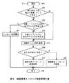
ここで、このような処理は図4に示す経路要求メッセージ受信処理手順RT1に従ったCPU12の制御のもとに行われる。実際上、各ノードA〜EのCPU12は、経路要求メッセージ20を受信すると、この経路要求メッセージ受信処理手順RT1をステップSP0において開始し、続くステップSP1において、その経路要求メッセージ20の「RREQ ID」のフィールド35に格納された経路要求メッセージIDを読み出し、これを経路要求メッセージ20の受信履歴としてRAM14に格納すると共に、当該受信履歴に基づいて、同じ経路要求メッセージIDが付与された経路要求メッセージ20を過去に受信したことがあるか否かを判断する。Here, such processing is performed under the control of the
そしてCPU12は、このステップSP1において否定結果を得るとステップSP5に進み、これに対して肯定結果を得ると、ステップSP2に進んで、その経路要求メッセージ20の中継ノードリスト20に自己のアドレスが存在するか否かを判断する。 If the
ここでこのステップSP2において肯定結果を得ることは、そのノードA〜Eがその経路要求メッセージ20自体を過去に中継したことがあることを意味し、かくしてこのときCPUは、ステップSP3に進んでこの経路要求メッセージ20を破棄し、この後ステップSP9に進んでこの経路要求メッセージ受信処理手順RT1を終了する。 Here, obtaining a positive result in step SP2 means that the nodes A to E have relayed the
これに対してステップSP2において否定結果を得ることは、そのノードA〜Eが、他の経路を経由して送信されてきた同じ経路要求メッセージIDをもつ経路要求メッセージ20を過去に中継したことがあるが、その経路要求メッセージ20自体は中継したことがないことを意味し、かくしてこのときCPU12は、ステップSP4に進んでその経路要求メッセージ20の中継ノードリスト20に自己のアドレスを加える。 On the other hand, obtaining a negative result in step SP2 means that the nodes A to E have relayed the
またCPU12は、この後ステップSP5に進んで、その経路要求メッセージ20が経由してきた経路の逆向き経路のエントリをノードSまでの経路として後述する経路エントリ挿入処理手順RT2(図8)に従って新たに自己の経路テーブル30(図7)に挿入する。 Further, the
さらにCPU12は、この後ステップSP6に進んで、その経路要求メッセージ20の「Destination Address」のフィールド36に記述された当該経路要求メッセージ20のあて先に基づいて、当該経路要求メッセージ20が自分宛のものであるか否かを判断する。Further CPU12 proceeds to step SP6 thereafter, the
そしてCPU12は、このステップSP6において否定結果を得ると、ステップSP7に進んで、当該経路要求メッセージ20の「Hop Count」のフィールド34に格納されたホップ数を「1」増加させたうえで、この経路要求メッセージ20をブロードキャストし、この後ステップSP9に進んでこの経路要求メッセージ受信処理手順RT1を終了する。CPU12 then obtains a negative result in step SP6, the process proceeds to step SP7, the hop count stored in the
これに対してCPU12は、ステップSP6において肯定結果を得ると、ステップSP8に進んでその経路要求メッセージ20に対する経路応答メッセージ23(図6)を生成し、これを自己の経路テーブル30に基づいて対応するノードC、Eにユニキャストした後、ステップSP9に進んでこの経路要求メッセージ受信処理手順RT1を終了する。 On the other hand, when the
なおこの実施の形態の場合、かかる経路要求メッセージ受信処理手順RT1のステップSP8において、CPU12は、同じ経路要求メッセージIDをもつ経路要求メッセージ20に対する応答として、同じID(以下、これを経路応答メッセージID(RREP ID)と呼ぶ)を付与した経路応答メッセージ23を生成するようになされている。 In this embodiment, in step SP8 of the route request message reception processing procedure RT1, the
すなわち、経路応答メッセージは、通常、経路要求メッセージの伝達時に設定された逆向き経路を通るようにユニキャストで送信されるが、本実施の形態においては逆向き経路が複数存在するため、経路応答メッセージ23を逆向き経路の数だけコピーしてマルチキャストで送信することとなる。 That is, the route response message is normally transmitted by unicast so as to pass through the reverse route set at the time of transmission of the route request message. However, since there are a plurality of reverse routes in this embodiment, the route response message The
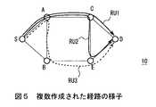
この場合において、例えば図5に示すように、ノードSから発信された経路要求メッセージ20がノードDに3つの経路(第1〜第3の経路RU1〜RU3)を経て到達した場合、ノードDは、第1の経路RU1を経て到達した経路要求メッセージ20に対する応答としてノードCに、第2の経路RU2を経て到達した経路要求メッセージ20に対する応答としてノードEに、第3の経路RU3を経て到達した経路要求メッセージ20に対する応答としてノードEにそれぞれ経路応答メッセージ23をユニキャストで送信するが、このときノードEはノードDを送信先(Destination Address)とする逆向き経路を2回設定してしまうことなる。これと同様の事態がノードAやノードSにおいても発生する。 In this case, for example, as illustrated in FIG. 5, when the
そこで、このアドホックネットワークシステム10においては、図18との対応部分に同一符号を付した図6に示すように、従来の経路応答メッセージ6(図18)を拡張して、「RREP ID」のフィールド24を設け、経路要求メッセージ20を受け取ったノードDが経路応答メッセージ23を返信する際、経路要求メッセージにおける経路要求メッセージIDと同様の経路応答メッセージIDをこのフィールド21に格納するようになされている。 Therefore, in this ad hoc
そして、経路応答メッセージ23を受け取ったノードA〜C、E、Sは、過去に同じ経路応答メッセージIDの経路応答メッセージ23を受信しており、かつノードSまでの逆向き経路が既に経路テーブル30に登録されている場合にはその経路応答メッセージ23を破棄し、これ以外の場合に図8について後述する経路エントリ挿入処理手順RT2に従ってその経路応答メッセージ23を発信したノードDまでの経路を自己の経路テーブル30に挿入する。 Then, the nodes A to C, E, and S that have received the
このようにしてこのアドホックネットワークシステム10においては、複数経路を作成する場合に生じ得る経路応答メッセージ23を送信したノード(ノードD)までの逆向き経路の多重設定を有効に防止し、かかる冗長さを確実に防止し得るようになされている。 In this way, in this ad hoc
(1−3)各ノードA〜E、Sにおける複数経路の管理方法
上述のようにこのアドホックネットワークシステム10においては、各ノードA〜E、Sは、データの通信開始時にデータの送信元であるノードS及び当該データの送信先であるノードD間の経路を複数作成する。そして各ノードA〜E、Sは、これら作成した経路を図17との対応部分に同一符号を付した図7に示す経路テーブル30を用いて管理している。(1-3) Management Method of Multiple Routes in Each Node A to E, S As described above, in this ad hoc
この経路テーブル30は、「Destination Address」、「Destination Sequence Number」、「Minimum Hop Count」、「Maximum Hop Count」、「Route List」及び「Precursor List」のフィールド51、52、311〜313、55から構成されるものであり、「Route List」のフィールド313に上述のような経路発見プロセスにより発見された送信先ノードA〜E、Sまでの各経路にそれぞれ対応させて作成された1又は複数の経路リスト32が格納され、「Minimum Hop Count」及び「Maximum Hop Count」の各フィールド311、312には、それぞれ当該経路発見プロセスにより発見された経路のうち最もホップ数が少ない経路の当該ホップ数又は最もホップ数が多い経路の当該ホップ数が格納される。The route table 30 includes
一方、経路リスト32は、「Hop Count」、「Next Hop」、「Life Time」及び「Link Quality」のフィールド331〜335を有し、「Hop Count」のフィールド331にその経路における送信先ノードA〜E、Sまでのホップ数、「Next Hop」のフィールド332にその経路における次ホップ、「Life Time」のフィールド333にその経路(次ホップ)の生存時間、「Link Quality」のフィールド334にその経路の品質が格納されている。そしてこの経路リスト32は、新たな経路が発見されるごとに作成されて経路テーブル30の対応する「Route List」のフィールド313に格納される。On the other hand, the
この場合、各経路リスト32の「Link Quality」のフィールド334には、経路の品質として、その経路の電波状況やパケットエラー率等の情報が記述される。そして、この経路の品質に関する情報はその経路が使用されるごとに順次更新される。In this case, the
また各経路リスト32は、「Life Time」のフィールド333に記述された生存時間によって生存の可否が管理され、対応する経路が使用されることなく生存時間が経過した場合には、その経路リスト32が経路テーブル30から自動的に削除される。And each
さらに各経路リスト32には、「Next List」のフィールド335が設けられており、対応する経路の次の優先順位を有する経路と対応する経路リストへ32のポインタがこのフィールド335に記述される。これにより必要時にはこのポインタに基づいて経路リスト32を優先順位に従って検索できるようになされている。Furthermore each
なお、この実施の形態においては、一般的に最短ホップで送信先ノードA〜E、Dに到達できる経路が最も性能が良いと考えられることから、経路の優先順位をホップ数が少ない順に付与するようになされている。 In this embodiment, since routes that can reach the destination nodes A to E and D with the shortest hop are generally considered to have the best performance, the route priorities are assigned in ascending order of the number of hops. It is made like that.
ここで、各ノードA〜E、SのCPU12は、上述のような経路テーブル30への新たな経路エントリの挿入処理を図8に示す経路エントリ挿入処理手順RT2に従って実行する。 Here, the
すなわちCPU12は、経路要求メッセージ20(図3)又は経路応答メッセージ23(図6)を受信すると、この経路エントリ挿入処理手順RT2をステップSP10において開始し、続くステップSP11において、自己の経路テーブル30にその経路要求メッセージ20の「Destination Address」のフィールド36(図3)又は経路応答メッセージ23の「Destination Address」のフィールド76(図6)に記述された当該経路要求メッセージ20又は経路応答メッセージ23の送信元ノードであるノードS又はノードDのアドレス(Destination Address)が存在するか否かを判断する。That is, when receiving the route request message 20 (FIG. 3) or the route response message 23 (FIG. 6), the
このステップSP11において否定結果を得ることは、そのノードA〜E、SにおいてノードS又はノードDまでの経路が未だ自己の経路テーブル30に登録されていないことを意味し、かくしてこのときCPU12は、ステップSP12に進んで、通常の経路エントリ挿入処理を実行する。 To obtain a negative result in this step SP11 means that the route to the node S or node D is not yet registered in the own route table 30 in the nodes A to E and S, and thus the
具体的には、その経路要求メッセージ20又は経路応答メッセージ23の「Originator Address」及び「Originator Sequence Number」をそれぞれ経路テーブルの対応する「Destination Address」又は「Destination Sequence Number」のフィールド51、52にコピーし、その経路要求メッセージ20又は経路応答メッセージ23の「Hop Count」を経路テーブル30の「Minimum Hop Count」及び「Maximum Hop Count」の各フィールド311、312にそれぞれコピーする。Specifically, “Originator Address” and “Originator Sequence Number” of the
またCPU12は、その経路要求メッセージ20又は経路応答メッセージ23の「Hop Count」を経路リスト32の「Hop Count」のフィールド331にコピーし、当該経路要求メッセージ20又は経路応答メッセージ23が格納されたパケットのヘッダに含まれる当該経路要求メッセージ20を送信してきた隣接ノードA〜E、Sのアドレスを経路リスト32の「Next Hop」のフィールド332にコピーし、さらに予め定められた生存時間を「Lifetime」のフィールド333に記述する一方、そのときの経路要求メッセージ20又は経路応答メッセージ23の受信状態に基づき検出されたその経路の電波状況やパケットエラー率等の品質を「Link Quality」のフィールド334に記述するようにして経路リスト32を作成し、これを経路テーブル40の「Route List」のフィールド313に格納する。The CPU12, copy the "Hop Count" of the
そしてCPU12は、このようにしてステップSP12において通常の経路エントリ挿入処理によりノードS又はノードDまでの経路を自己の経路テーブル30に登録すると、この後ステップSP23に進んでこの経路エントリ挿入処理手順RT2を終了する。 When the
これに対してステップSP11において肯定結果を得ることは、その経路要求メッセージ20又は経路応答メッセージ23の送信元であるノードS又はノードDまでの1又はそれ以上の経路が既に自己の経路テーブル30に登録されていることを意味し、かくしてこのときCPU21は、ステップSP13に進んで、経路テーブル30を検索することにより、その経路要求メッセージ20又は経路応答メッセージ23を送信してきた隣接ノードA〜E、Sを「Next Hop」とする対応する経路リスト32が存在するか否かを判断する。 On the other hand, obtaining a positive result in step SP11 means that one or more routes to the node S or the node D, which is the transmission source of the
そしてCPU12は、このステップSP13において肯定結果を得ると、ステップSP21に進み、これに対して否定結果を得るとステップSP14に進んで、経路リスト数が1つの「Destination Address」に対して登録できる最大数であるか否かを判断する。そしてCPU12は、このステップSP14において否定結果を得るとステップSP16に進み、これに対して肯定結果を得るとステップSP15に進んで、その「Destination Address」に対応する経路リスト32の中から時間的に最も古い(すなわち作成後、最も時間が経過した)経路リスト32を削除した後ステップSP16に進む。 If the
またCPU12は、ステップSP16において、その経路要求メッセージ20又は経路応答メッセージ23の「Hop Count」のフィールド34(図3)、74(図6)に記述されているホップ数が経路テーブル30の対応する「Maximum Hop Count」のフィールド312に記述されたホップ数(最大ホップ数)よりも大きいか否かを判断する。そしてCPU12は、このステップSP16において否定結果を得るとステップSP18に進み、これに対して肯定結果を得るとステップSP17に進んで、経路テーブル30の対応する「Maximum Hop Count」のフィールド312に記述されているホップ数を、その経路要求メッセージ20又は経路応答メッセージ23の「Hop Count」のフィールド34(図3)、74(図6)に記述されているホップ数に書き換えた後ステップSP18に進む。In step SP16, the
さらにCPU12は、ステップSP18において、その経路要求メッセージ20又は経路応答メッセージ23の「Hop Count」のフィールド34(図3)、74(図6)に記述されているホップ数が経路テーブル30の対応する「Minimum Hop Count」のフィールド311に記述されたホップ数(最小ホップ数)よりも小さいか否かを判断する。そしてCPU12は、このステップSP18において否定結果を得るとステップSP20に進み、これに対して肯定結果を得るとステップSP19に進んで、経路テーブル30の対応する「Minimum Hop Count」のフィールド311に記述されているホップ数を、その経路要求メッセージ20又は経路応答メッセージ23の「Hop Count」のフィールド34(図3)、74(図6)に記述されているホップ数に書き換えた後ステップSP20に進む。Further, in step SP18, the
続いてCPU12は、ステップSP20において、ステップSP12について上述したのと同様にしてその経路に対応する経路リスト32を作成し、これを経路テーブル30の対応する「Route List」のフィールド313に登録する。またこのときCPU12は、同じ「Destination Address」の経路リスト32の優先順位を各経路リスト32の「Hop Count」に基づいて定め、これに応じてこれら対応する経路リスト32の「Next List」のフィールド335を、次の優先順位をもつ経路と対応する経路リスト32へのポインタに必要に応じて書き換える。Subsequently CPU12 at step SP20, to create a
次いでCPU12は、ステップSP21に進んで、ステップSP20において新たに挿入した経路リスト32の「Lifetime」を更新すると共に、この後ステップSP22に進んで当該経路リスト32の「Link Quality」をそのとき検出した対応する経路の品質に応じて更新し、さらにステップSP23に進んでこの経路エントリ挿入処理手順RT2を終了する。 Next, the
このようにして各ノードA〜E、Sは、新たな経路を自己の経路テーブル30において管理し得るようになされている。 In this way, each of the nodes A to E and S can manage a new route in its route table 30.
(1−4)データ通信に関する各ノードA〜E、Sの具体的な処理内容
経路要求メッセージ20の送信元であるノードSがこの経路要求メッセージに対する経路応答メッセージ23を当該経路要求メッセージ20の送信先であるノードDから受け取ると、そのノードSからノードDまでの経路が設定されたことになる。(1-4) Specific Processing Contents of Each Node A to E, S Regarding Data Communication The node S that is the transmission source of the
本実施の形態においては、このとき設定された経路数分の経路応答メッセージ23をノードSが受信することになるが、最初に受け取った経路応答メッセージ23が経由した経路が必ずしもホップ数が少ない品質の高い経路とは限らない。 In the present embodiment, the node S receives the
そこで、このアドホックネットワークシステム10において、経路要求メッセージ20の送信元であるノードSは、最初の経路応答メッセージ23を受信してから予め定められた所定時間が経過し又は予め定められた所定数の経路応答メッセージ23を受信するのを待ち、受信した各経路応答メッセージ23がそれぞれ経由した経路のうち、ホップ数が最も少ない経路を選択して、その経路を通じて経路要求メッセージ23の送信先であるノードDとの通信を開始するようになされている。 Therefore, in this ad hoc
なおこのときノードSは、経路応答メッセージ23に含まれる経路応答メッセージIDに基づいて、そのとき到達した経路応答メッセージ23が同じノードDから同じ時間に送信されたものであるか否かを判断するようになされ、これにより誤った経路の選択が行われるのを未然に防止し得るようになされている。 At this time, the node S determines based on the route response message ID included in the
ここでこのようなノードSにおける処理は、図9に示す経路応答メッセージ受信処理手順RT3に従ったCPU12(図2)の制御のもとに行われる。すなわちノードSのCPU12は、経路要求メッセージ20を送信後、最初の経路応答メッセージ23を受信するとこの経路応答メッセージ受信処理手順RT3をステップSP30において開始し、続くステップSP32において、最初の経路応答メッセージ23を受信してから予め定められた所定時間が経過したか否かを判断する。 Here, such processing in the node S is performed under the control of the CPU 12 (FIG. 2) according to the route response message reception processing procedure RT3 shown in FIG. That is, when the
そしてCPU12は、このステップSP32において否定結果を得るとステップSP32に進んで新たな経路応答メッセージ23を受信しか否かを判断し、このステップSP32において否定結果を得るとステップSP32に戻る。 If the
これに対してCPU12は、ステップSP32において肯定結果を得るとステップSP33に進んで、最初に受信した経路応答メッセージ23を含めて所定数の経路応答メッセージ23を受信したか否かを判断する。 On the other hand, if the
そしてCPU12は、このステップSP33において否定結果を得るとステップSPに戻り、この後ステップSP32又はステップSP33において肯定結果を得るまでステップSP32−SP32−SP33−SP32のループを繰り返す。 If the
そしてCPU12は、やがて最初の経路応答メッセージ23を受信してから所定時間が経過し、又は所定数の経路応答メッセージ23を受信することにより、ステップSP32又はステップSP33において肯定結果を得ると、ステップSP34に進んでこの経路応答メッセージ受信処理手段RT3を終了し、この後経路テーブル30の対応する「Route List」に登録されている最も優先順位の高い経路リスト32の「Next Hop」のフィールド332(図7)にアドレスが登録されているノードA、Bにデータをユニキャストで送信し始める。When the
一方、このようにしてノードSからのデータの送信が開始されると、このデータが送信されてきたノードA〜Eは、自己の経路テーブル30を検索して当該データの送信先ノード(すなわちノードD)までの経路のエントリを検出すると共に、これにより検出された対応する経路リスト32の中から最も優先順位の高い経路の経路リスト32における「Next Hop」のフィールド332(図7)に登録されたノードA〜Eに対して当該データをユニキャストする。On the other hand, when the transmission of data from the node S is started in this manner, the nodes A to E that have transmitted this data search their own route table 30 and transmit the data to the destination node (that is, the node). D) is detected, and is registered in the field 332 (FIG. 7) of “Next Hop” in the
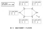
例えば図10のように各ノードA〜E、Sにおいて経路の設定が完了した状態において、例えばノードSからノードAにデータが送信された場合、ノードAは、ノードDを送信先(Destination Address)とする経路リスト32として、ノードCを「Next Hop」とする経路リストと、ノードBを「Next Hop」とする経路リスト32とを有しているが、ノードCを「Next Hop」とする経路リスト32の方がホップ数が少ないため優先順位が高く設定される。従って、ノードAは、ノードSから送信されてきたデータをユニキャストでノードCに転送することとなる。 For example, when data is transmitted from the node S to the node A in the state where the route setting is completed in each of the nodes A to E and S as shown in FIG. 10, the node A sends the node D to the destination (Destination Address). The
同様に、ノードCは、ノードDを送信先とする経路リスト32として、ノードDを「Next Hop」とする経路リストと、ノードEを「Next Hop」とする経路リストとを有しているが、ノードDを「Next Hop」とする経路リスト32の方がホップ数が少ないため優先順位が高く設定される。従って、ノードCは、ノードAから送信されてきたデータをユニキャストでノードDに転送する。 Similarly, the node C has, as a
なおこの例の場合、ノードSは、ノードDを送信先とする経路リスト32として、ノードAを「Next Hop」とする経路リスト32と、ノードBを「Next Hop」とする経路リスト32とを有しており、いずれの経路リスト32も「Hop Count」が同じであるが、このような場合にはノードSはその経路のホップ数以外の予め定められた要素(例えば経路の品質(Link Quality))を考慮して、最適な経路を選択するようになされている。 In this example, the node S includes a
一方、ノードS及びノードD間の通信開始後、そのデータが経由する経路を構成するいずれかのノードA〜E、S間において通信障害が発生すると、送信側のノードA〜C、E、S間は、自己の保有する経路テーブル30に基づいて、そのデータの送信先であるノードDを「Destination Address」とするエントリに含まれるいくつかの経路リスト32の中から、そのときまで使用していた経路の次の優先順位を有する経路の経路リスト32を新たに選択し、その後はこの経路リスト32の「Next Hop」として記述されたノードA〜Eにデータを送信する。 On the other hand, after a communication between the node S and the node D is started, if a communication failure occurs between any of the nodes A to E and S configuring a route through which the data passes, the transmitting side nodes A to C, E and S In the meantime, based on the route table 30 owned by itself, from among several route lists 32 included in the entry having the node D as the data transmission destination as “Destination Address”, it is used until that time. The
例えば図10の例において、ノードA及びノードC間において通信障害が発生した場合、ノードAは、ノードCを経由する経路の次の優先順位が付与されたノードBを経由する経路を選択し、その経路リスト32の「Next Hop」に記述されたノードBに対してデータを転送することとなる。 For example, in the example of FIG. 10, when a communication failure occurs between the node A and the node C, the node A selects a route via the node B to which the next priority order of the route via the node C is given, Data is transferred to the node B described in “Next Hop” in the
ここで、このような各ノードA〜C、E、Sにおける処理は、図11に示す通信処理手順RT4に従ったCPU12の制御のもとに行われる。すなわち各ノードA〜C、E、SのCPU12は、データの送信を開始し又はデータが送信されてくるとこの通信処理手順RT4をステップSP40において開始し、続くステップSP41において、送信されてきたデータを優先順位が最も高い経路の経路リスト32における「Next Hop」のフィールド332(図7)に記述されたノードA〜Eにユニキャストする。Here, the processing in each of the nodes A to C, E, and S is performed under the control of the
続いてCPU12は、ステップSP42に進んで、かかる通信相手のノードA〜Eとの間の電波状況等に基づいて当該ノードA〜Eとの間で通信障害が発生したか否かを判断する。 Subsequently, the
そしてCPU12は、このステップSP42において否定結果を得るとステップSP43に進み、前のノードA〜C、E、Sから送信されてくるデータの送信状況に応じてデータの送信元(ノードS)及び送信先(ノードD)間における通信が終了したか否かを判断する。 If the
CPU12は、このステップSP43において否定結果を得るとステップSP41に戻り、この後ステップSP42又はステップSP43において肯定結果を得るまでステップSP41−SP42−SP43−SP41のループを繰り返す。 If the
そしてCPU12は、やがてステップSP42において肯定結果を得ると、ステップSP44に進んで、そのときまで使用していた経路リスト32の「Next List」のフィールド335(図7)に格納されたポインタを手がかりに次の優先順位を有する経路の経路リスト32を検索し、使用する経路リスト32をその経路リスト32に切り換えた後ステップSP41に戻る。かくしてCPU12は、この後ステップSP44において選択した経路リスト32の「Next Hop」のフィールド332(図7)に記述されたノードA〜Eに対してデータをユニキャストすることとなる。When the
そしてCPU12は、この後ステップSP43において肯定結果を得ると、ステップSP45に進んで、この通信処理手順RT4を終了する。 If the
(1−5)経路アクティベーションパケットを用いたアクティベート方法
次に、このアドホックネットワークシステム1における経路アクティベーションパケットを用いたアクティベート(正規経路化)方法について説明する。(1-5) Activation Method Using Route Activation Packet Next, an activation (regular route) method using a route activation packet in the ad hoc
上述のようにこのアドホックネットワークシステム1では、従来の経路要求メッセージ2(図16)を拡張して設けた中継ノードリスト21に基づいて、経路要求メッセージ20(図3)がこれを中継するノードA〜C、E間においてループするのを防止しながら各ノードA〜E、Sにおいて複数経路を作成する。 As described above, in the ad hoc
このような複数経路を作成する経路制御方式では、どの経路を使用するかについては経路を保持する中継ノードA〜C、Eに任せることとなり、経路要求メッセージ20の送信元のノードSが経路を選択することができない。仮に複数経路のうち任意の経路を選択できたとしても、同じ送信元のノードSから発信されるデータパケットは全て同じ経路を通ることとなるため、データの属性(テキストデータ、コマンドデータ、AVデータ等)毎に異なる経路を利用したり、時間と共に変化するリンク品質を基準に自由に経路を変更したり、という複数経路の効率的な利用を図ることが困難となる。 In such a route control method for creating a plurality of routes, which route is used is left to the relay nodes A to C and E that hold the route, and the node S that is the source of the
そこで、このアドホックネットワークシステム1においては、上述のようにして各ノードA〜E、Sが複数経路を作成後、データの送信元であるノードSがデータの送信先であるノードDまでの通信経路として使用する経路に対する要求を格納したパケット(以下、これを経路アクティベーションパケットと呼ぶ)を発信する一方、これを受信した各ノードA〜Eが、作成した複数経路の中からこの経路アクティベーションパケットに格納された要求に応じて使用経路を設定したり、経路に対する各種設定を行ようになされ、これにより各ノードA〜E、Sがそれぞれ作成した複数経路の中からデータ送信元であるノードSの要求に応じた最適な経路を選択的に使用させることができるようになされている。 Therefore, in this ad hoc
図11は、このような経路アクティベーションパケット40の構成を示すものである。この図11からも明らかなように、経路アクティベーションパケット40は、固定的な「Type」、「Flag」、「Reserved」、「Hop Count」、「Message ID」、「Destination Address」及び「Originator Address」のフィールド411〜417と、使用経路に対する要求に応じて付加又は削除される可変的な「Required Link Quality」、「Flow ID」、「Lifetime」及び「Requirements」のフィールド418〜4111とから構成される。FIG. 11 shows the configuration of such a
そして、この経路アクティベーションパケット40の「Type」のフィールド411には、このパケットが経路アクティベーションパケット(RACT)又はそれに対する返答である後述の経路アクティベーション返答パケット(RACT−ACK)のいずれであるかを示すコードが格納される。Then, in the field411 of the "Type" of this
また「Flag」のフィールド412には、デバッギング等に使用するためのフラグが格納される。経路アクティベーションパケット40は、データの送信元から送信先に向けて発信され、原則として、これに対する返答である経路アクティベーション返答パケットが後述のようにこのデータの送信先から送信元に向けて発信されるが、予めフラグを設定しておくことで、いずれか一方向のみ経路を設定することもできる。Also in the field 412 of the "Flag" is a flag for use in debugging and the like are stored. The
「Hop Count」のフィールド414にはホップ数(初期値は「0」)が格納され、「Message
ID」のフィールド415には、その経路アクティベーションパケット40に付与されたID(以下、これをメッセージIDと呼ぶ)が格納される。なおこのメッセージIDは、1つの経路アクティベーションパケットに対して固有のものであり、再送しても同じものが使用される。Hop count in field 414 of the "Hop Count" (initial value is "0") is stored, "Message
The field 415 of ID ", the
さらに経路アクティベーションパケット40の「Destination
Address」のフィールド416には、この経路アクティベーションパケット40のあて先ノードのアドレスが格納され、「Originator Address」には、この経路アクティベーションパケット40を発信したノードのアドレスが格納される。Furthermore, “Destination” of the
The field 416 of the Address ", the address of the destination node of the
一方、経路アクティベーションパケット40の「Required
Link Quality」のフィールド418には、通信経路として要求される経路の品質について閾値として設定された数値が格納され、「Flow ID」のフィールド419には、経路に設定するID(以下、これをフローIDと呼ぶ)が格納される。このフローIDは、同じ送信先でも異なるデータフローは異なる経路を使用して効率的に転送する等の用途に使用される。On the other hand, “Required” of the
Field 418 of the Link Quality "is stored value set as a threshold value for the quality of the path required as a communication path, the field 419 of the" Flow ID "is ID to be set to the path (hereinafter, Is called a flow ID). This flow ID is used for such purposes as efficiently transferring different data flows using different paths even at the same destination.
また経路アクティベーションパケット40の「Lifetime」のフィールド4110には、その経路に設定すべき生存時間が格納され、不使用かつ消去間近にある経路の生存時間を延長させるために使用される。さらに「Requirements」フィールド4111には、経路に対する自由な要求を記述するために使用される。Also in the field 4110 of the "Lifetime" of the
なお、これら「Required Link
Quality」、「Flow ID」、「Lifetime」及び「Requirements」の各フィールドフィールド418〜4111は、通信経路として要求される条件に応じて任意に付加又は省略される。因みに、以下においては、「Required Link Quality」、「Flow ID」、「Lifetime」及び「Requirements」の各フィールドフィールド418〜4111にそれぞれ格納される使用経路に対する要求内容をまとめて経路要求パラメータと呼ぶものとする。These “Required Link”
The field fields 418 to 4111 of “Quality”, “Flow ID”, “Lifetime”, and “Requirements” are arbitrarily added or omitted according to the conditions required for the communication path. Incidentally, in the following, the request contents for the used routes stored in the field fields 418 to 4111 of “Required Link Quality”, “Flow ID”, “Lifetime”, and “Requirements” are collectively shown as a route request parameter. Shall be called.
この経路要求パラメータの値は、データ送信元ノードにおけるデータ送信を希望したアプリケーションの要求に応じて、又は経路アクティベーションパケット40の再送の頻度が高い場合や伝送時のパケットロス率が高い場合などのデータの送信状態などに基づいて設定される。 The value of this route request parameter depends on the request of the application that desires data transmission at the data transmission source node, or when the frequency of retransmission of the
(1−6)経路アクティベーションパケット40の適用例
次に、かかる経路アクティベーションパケット40の適用例について、一定の経路品質を有する経路のみをアクテリベートする場合を例に説明する。なお、以下においては、経路の品質を、無線の電波状況やエラーレートなどを抽象化した値であると定義する。つまり数値が高い場合は経路の品質が良く、エラーレートが低い経路であるものとする。(1-6) Application Example of
データの送信元であるノードSは、まず最初に、経路に対する要求を決定する。例えば経路の品質について言えば、統計的な情報から満足できる通信が行える環境を事前に調査し、フローIDなどその他の複雑な情報についてはアプリケーションからの要求を受け入れるような当該アプリケーションとのインターフェースを用意しておくことで要求を取得する。 The node S that is the data transmission source first determines a request for a route. For example, in terms of route quality, we will investigate in advance the environment that allows satisfactory communication based on statistical information, and prepare an interface with the application to accept requests from the application for other complex information such as flow IDs. Get the request by keeping it.
そしてノードSは、例えばデータ送信を希望するアプリケーションから『経路品質が閾値「50」以上の経路のみをアクティベーションしろ』という要求があった場合、経路アクティベーションパケット40の「Required Link Quality」のフィールド415に「50」という数値を格納し、さらに「Destination Address」のフィールド416にデータの送信先であるノードDのアドレスを格納すると共に、「Originator Address」のフィールド417に自己のアドレスを格納するようにして経路アクティベーションパケット40を生成し、これを発信する。Then, for example, when there is a request for “activate only a route whose route quality is equal to or higher than the threshold value“ 50 ”” from an application that desires data transmission, the node S field of “Required Link Quality” of the
一方、この経路アクティベーションパケット40を受信した他のノードA〜Eは、そのあて先(「Destination Address」のフィールド416にアドレスが格納されたノードであって、ここではノードD)への経路エントリが自己の経路テーブル30(図7)に存在するか否かを調べ、存在しない場合には経路アクティベーションエラーを当該経路アクティベーションパケット40の送信元のノードSに送信する。On the other hand, the other nodes A~E having received this
これに対してノードA〜Eは、かかる経路エントリが経路テーブル30に存在する場合には、そのあて先への経路リスト32(図7)を検索することにより、経路の品質(「Link Quality」)が経路アクティベーションパケット40の「Required Link Quality」のフィールド415に格納された閾値(「50」)を超えている経路が存在するか否かを調べる。On the other hand, when such a route entry exists in the route table 30, the nodes A to E search the route list 32 (FIG. 7) to the destination to thereby obtain the route quality (“Link Quality”). there examine whether there is a path that exceeds the
そしてノードA〜Eは、存在しない場合にはノードSに対して経路アクティベーションエラーを送信する。なお、この経路アクティベーションエラーは、例えばIP層のICMPメッセージなどで代用することが可能である。Then, the nodes A to E transmit a route activation error to the node S when they do not exist. This path activation error can be substituted with, for example, an IP layer ICMP message.
これに対してノードA〜Eは、かかる閾値を超える品質を有する経路が1つでも存在する場合、その経路の経路リスト32の「Next Hop」のフィールド322に記述されたノードA〜EをノードSからノードDへのデータ送信時の正規の経路として設定する。Node A~E contrast, if the path having a quality exceeding such threshold exists even one node A~E described in the
因みに、何をもって正規の経路としてみなすかは、このアドホックネットワークシステム1の経路制御方式に依存する。例えば、複数の経路をもっているが、通常は1つだけ「Valid」のフラグを設定してあるという方式では、該当する経路のみを「Valid」にして残りを「Invalid」にすることが経路をアクティベーションすることになる。このアドホックネットワークシステム1においては、経路に優先順位が設定されているため、その経路の優先順位を最も高いものとすることで、正規の経路として設定する。 Incidentally, what is regarded as a regular route depends on the route control method of the ad hoc
そしてノードA〜Eは、このような経路のアクティベーションが完了すると、経路アクティベーションパケット40のあて先が自己でない限り、この経路アクティベーションパケット40「Hop Count」のフィールド414に格納されたホップ数を「1」増加させたうえでこれをアクティベーションされた経路の次ホップのノードA〜Eに向けて転送する。The node A~E, upon activation of such a pathway is completed, as long as the destination of the
かくして、この後これと同様の処理が対応する各ノードA〜C、Eにおいて順次行われ、これによりやがてこの経路アクティベーションパケット40がそのあて先であるノードDにまで伝達される。 Thus, thereafter, the same processing is sequentially performed in the corresponding nodes A to C and E, whereby the
そして、このようにして経路アクティベーションパケット40を受け取ったノードDは、上述のような経路のアクティベーションを行った後、その経路アクティベーションパケット40の「Type」のフィールド411に格納されたコードを経路アクティベーション応答パケットのコードに変更し、「Destination Address」のフィールド416に格納されたアドレスを経路アクティベーションパケット40の送信元であるノードSのアドレスに変更し、かつ「Originator Address」のフィールド417に格納されたアドレスを自己のアドレスに変更するようにして経路アクティベーション応答パケット50を生成し、これをアクティベーションされた経路の次ホップのノードC、Eに向けて転送する。Then, the code node D that received the
かくして、この経路アクティベーション応答パケット50が経路アクティベーションパケット40のときと同様にして、各ノードA〜C、EにおいてノードDまでの経路のアクテリベート処理が行われながらノードSに向けて順次伝達され、やがてノードSがこの経路アクティベーション応答パケット50を受け取ることで、経路アクティベーションが完了する。そして各ノードA〜Eは、この後ノードS及びノードD間での通信において、かかる経路アクティベーションパケット40に格納されたフローIDが付されたデータが送信されてきたときには、このとき設定した経路を通信経路としてデータの送受を行う。このようにしてこのアドホックネットワーク10においては、データ送信元ノードにおけるアプリケーションの要求等に応じた適切な経路を設定する。 Thus, in the same way as when the route
なおノードSは、経路アクティベーションパケット40を送信後、所定時間内にノードDからの経路アクティベーション応答パケット50を受け取ることができなかった場合や、途中で経路アクティベーションエラーを受け取った場合には、経路アクティベーションが行われるまで順次条件を緩和するように経路要求パラメータを再設定しながら経路アクティベーションパケット40を順次再送する。 Note that the node S does not receive the route
従って、この例のように経路品質が「50」以上であることが当初の経路アクティベーションの条件であった場合、ノードSは、経路アクティベーションパケット40の再送時、経路アクティベーションパケット40の「Required Link Quality」のフィールド418に格納された閾値の値を「50」から順次少しずつ下げた経路アクティベーションパケット40を順次生成して、これを再送することとなる。Therefore, when the initial route activation condition is that the route quality is “50” or higher as in this example, the node S retransmits the
以上、一定の経路品質を有する経路のみをアクテリベートする場合を例に説明したが、他の要求、例えば経路に所望のフローIDを設定する場合や、経路に生存時間を設定する場合、ユーザ等が要求する他の何らかの条件を満たす経路をアクテリベートする場合、さらには所望する条件の2以上を全て満たす経路をアクテリベートし、又はその経路に所望する設定を行う場合も同様の処理が行われる。 As described above, the case where only a route having a certain route quality is activated has been described as an example, but other requests, for example, when setting a desired flow ID for a route, when setting a lifetime for a route, a user, etc. The same processing is performed when activating a route that satisfies some other condition required by, and also activating a route that satisfies all two or more of the desired conditions, or making a desired setting for the route. .
実際上、ノードSは、経路に所望のフローIDを設定する場合には、経路アクテリベートパケット40の「Flow ID」のフィールド419にそのフローIDを格納し、一定時間以上の生存時間を有する経路をアクテリベートさせる場合には、「Lifetime」のフィールド4110に最低限必要な経路の生存時間を格納し、ユーザ等が要求する他の何らかの条件を満たす経路をアクテリベートさせる場合には、「Requirements」のフィールドフィールド4111にその条件を格納するようにして経路アクテリベートパケット40を生成し、これを発信する。In practice, node S, to set the desired flow ID to the route stores the flow ID field 419 of the "Flow ID" path
そして、この経路アクテリベートパケット40を受信したノードA〜Eは、当該経路アクテリベートパケット40に格納された全ての要求を満たす経路をノードS及びノードD間における通信経路として設定したり、その経路の生存時間の更新やその経路に対するフローIDの対応付け等を行い、この後ノードSからノードDへのデータ送信時には、この経路を利用して当該データを順次転送する。 Then, the nodes A to E that have received the route activate
このようにしてこのアドホックネットワーク10においては、データ送信元が、アプリケーションの要求や所望する経路品質の経路を使用経路として設定したり、その経路に対して生存時間の更新やフローIDの対応付け等を行い得るようになされ、これによりデータの属性に応じた細やかな経路設定や経路のメンテナンス等を行い得るようになされている。 In this way, in this ad hoc
(1−7)経路アクティベーションにおけるCPU12の処理
ここで、経路アクティベーションにおける各ノードA〜Eの上述のような各種処理は図12に示す経路アクティベーションパケット送信処理手順RT4に従ったCPU12(図2)の制御のもとに行われる。(1-7) Processing of
実際上、経路アクティベーションパケット40の送信元であるノードSにおいて、CPU12は、ユーザの要求やデータパケットの送信状態に応じて指定された経路に対するアクティベートの要求を受けると、この経路アクティベーションパケット送信処理手順RT4をステップSP40から開始し、続くステップSP41において、そのアクティベートの要求に応じた経路アクティベーションパケット40を送信した後、ステップSP42に進んで、当該送信時を基準にタイマ16(図2)を起動する。 In practice, in the node S that is the transmission source of the
続いてCPU12は、ステップSP43に進んで、所定方式の経路アクティベーションエラーを受信したか否かを判断する。そしてCPU12は、このステップSP43において肯定結果を得るとステップSP44に進み、経路アクティベーション返答パケット50を受信したか否かを判断する。 Subsequently, the
ここでこのステップSP44において肯定結果を得ることは、ノードSが経路アクティベーション返答パケット50を受信したことよって双方向での経路アクティベートが成功したことを意味し、このときCPU12は、ステップSP45に進んで、アクティベートした経路を介したデータの送信処理を開始した後、ステップSP46に進んでこの経路アクティベーションパケット送信処理手順RT4を終了する。 Here, obtaining a positive result in step SP44 means that the path activation in both directions has succeeded because the node S has received the path
これに対してステップSP44において否定結果を得ることは、経路アクティベーション返答パケット50を未だ受信していないことを意味し、このときCPU12は、ステップSP47に進んで、予め設定されたタイムアウト時間を超えたか否かをタイマ16(図2)のカウント値に基づいて判断する。 On the other hand, obtaining a negative result in step SP44 means that the route
このステップSP47において肯定結果を得ると、このことはタイムアウトになったことを意味し、このときCPU12は、ステップSP48に進んで、経路アクティベーションパケット40の再送処理を行うと共に、ステップSP49に進んで、必要に応じて経路要求パラメータの再設定を行った後、再度ステップSP42に戻って、この後同様の処理を繰り返す。 If an affirmative result is obtained in step SP47, this means that a time-out has occurred. At this time, the
これに対してステップSP47において否定結果を得ることは未だタイムアウトになっていないことを意味し、このときCPU12は、ステップSP43に戻って経路アクティベーションエラーの受信判断から順次同様の処理を繰り返す。 On the other hand, obtaining a negative result in step SP47 means that the time-out has not yet occurred. At this time, the
また上述したステップSP43において、CPU12が、肯定結果、すなわち経路アクティベーションエラーを受信したと判断した場合には、ステップSP48に進んで、経路アクティベーションパケット40の再送処理を行う。 In step SP43 described above, if the
このようにして経路アクティベーションパケット40の送信元であるノードSのCPU12は、ユーザの要求等に応じて他のノードA〜Eに対する経路のアクテリベートを行う。 In this way, the
一方、かかる経路アクティベーションパケット40を受信したノードA〜EのCPU12は、図13に示す経路アクティベーションパケット受信処理手順RT5に従って経路のアクティベートを実行する。 On the other hand, the
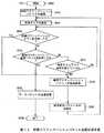
すなわちノードA〜EのCPU12は、経路アクティベーションパケット40を受信すると、この経路アクティベーションパケット受信処理手順RT5をステップSP50において開始し、続くステップSP51において、その経路アクティベーションパケット40の「Destination Address」のフィールド416に格納されたアドレスに基づいて、自己の経路テーブル30(図7)にこの経路アクティベーションパケット40のあて先までの経路エントリが存在するか否かを判断する。That is, when receiving the
そしてCPU12は、このステップSP51において肯定結果を得るとステップSP52に進み、その経路エントリに含まれる各経路リスト32の中に経路要求パラメータに合致した次ホップが存在するか否かを判断する。すなわちCPU12は、経路アクティベーションパケット40のあて先までの経路の中に経路要求パラメータとして規定された経路品質等の全ての条件を満たす経路が存在するか否かを判断する。 If the
このステップSP52において肯定結果を得ることは、経路要求パラメータとして規定された条件を満たす経路が存在することを意味し、このときCPU12は、ステップSP53に進んで、この次ホップ(経路)を正規の経路として設定すると共に、その経路に対して生存時間等の必要な設定を行った後、続くステップSP54に進んで、経路アクティベーションパケット40の「Hop Count」のフィールド414に格納されたホップ数を「1」増加させる。Obtaining an affirmative result in step SP52 means that there is a route that satisfies the conditions specified as the route request parameter. At this time, the
続いてCPU12は、ステップSP55に進んで、その経路アクティベーションパケット40の「Destination Address」のフィールド416に格納されたアドレスに基づいて、当該経路アクティベーションパケット40のあて先がノードであるか否かを判断し、肯定結果を得ると、ステップSP56に進んで、この経路アクティベーションパケット40に対する経路アクティベーション応答パケット50を生成し、これをアクテリベートした経路のノードC、Eに送信した後、ステップSP57に進んでこの経路アクティベーションパケット受信処理手順RT5を終了する。Subsequently CPU12 proceeds to step SP55, based on the field 41 are stored in the6 address of the "Destination Address" of the
これに対してCPU12は、ステップSP55において否定結果を得ると、ステップSP58に進んで、経路アクティベーションパケット50をアクティベートした経路のノードA〜Eに対して送信(ユニキャスト)した後、ステップSP57に進んでこの経路アクティベーションパケット受信処理手順RT5を終了する。 On the other hand, if the
一方、上述したステップSP51において否定結果を得ることは、自己の経路テーブル30(図7)にこの経路アクティベーションパケット40のあて先ノード(ノードD)までの経路エントリが存在しないことを意味し、このときCPU12は、ステップSP59に進んで、経路アクティベーションエラーをこの経路アクティベーションパケット40の送信元であるノードSに対して送信した後に、ステップSP57に進んでこの経路アクティベーションパケット受信処理手順RT5を終了する。 On the other hand, obtaining a negative result in the above-described step SP51 means that there is no route entry to the destination node (node D) of the
さらに上述したステップSP52において否定結果を得ることは、自己の経路テーブル30に登録されている当該経路アクティベーションパケット40のあて先ノード(ノードD)までの経路エントリに含まれる経路リスト30の中に経路要求パラメータとして規定された条件を満たす次ホップ(経路)が存在しないことを意味し、このときCPU12は、ステップSP59に進んで、この経路アクティベーションパケット40の送信元であるノードSに対して経路アクティベーションエラーを送信した後に、ステップSP57に進んでこの経路アクティベーションパケット受信処理手順RT5を終了する。 Further, obtaining a negative result in the above-described step SP52 is that the route is included in the route list 30 included in the route entry to the destination node (node D) of the
このようにして経路アクティベーションパケット40を受信した各ノードA〜EのCPU12は、経路アクティベーションパケット40に含まれる経路要求パラメータに応じた経路をアクテリベートする。 The
(2)本実施の形態の動作及び効果
以上の構成において、このアドホックネットワークシステム1では、データ通信開始時に各ノードA〜E、Sにおいて複数の経路をそれぞれ設定した後、データの送信元となるノードSがアプリケーションの要求等に応じた経路要求パラメータを格納した経路アクティベーションパケット40を発信する。そしてこの経路アクティベーションパケット40を受信した各ノードA〜Eは、この経路アクティベーションパケット40に含まれる経路要求パラメータに基づき、その条件を満たす経路を通信経路として設定したり、その経路に対して必要な設定を行う。(2) Operation and effect of the present embodiment In the above configuration, the ad hoc
従って、このアドホックネットワークシステム10では、データ通信開始時に各ノードA〜E、Sにおいて作成された複数の経路の中から、データ送信元のアプリケーションの要求等や、データパケットの属性等に応じた経路の設定を自由に行うことができ、その分最適な使用経路をすることができる。 Therefore, in this ad hoc
以上の構成によれば、データ通信開始時に各ノードA〜E、Sにおいて複数の経路をそれぞれ設定した後、データの送信元となるノードSがアプリケーションの要求等に応じた経路要求パラメータを格納した経路アクティベーションパケット40を発信し、これを受信した各ノードA〜Eが当該経路アクティベーションパケット40に含まれる経路要求パラメータに基づき、その条件を満たす経路を通信経路として設定したり、その経路に対して必要な設定を行うようにしたことにより、最適な使用経路を設定することができ、かくして信頼性の高いアドホックネットワークシステムを実現し得る。 According to the above configuration, after setting a plurality of paths in each of the nodes A to E and S at the start of data communication, the node S that is a data transmission source stores a path request parameter corresponding to an application request or the like. Based on the route request parameter included in the
(3)他の実施の形態
なお上述の実施の形態においては、本発明を、AODVプロトコルのアドホックネットワーク10及びこれを構成するノードA〜E、Sに適用するようにした場合について述べたが、本発明はこれに限らず、複数の通信端末により構成され、第1の通信端末から発信されて第2の通信端末を経由して第3の通信端末に送信される第1のメッセージ及び当該第1のメッセージに対して第3の通信端末から発信されて第2の通信端末を経由して第1の通信端末に送信される第2のメッセージに基づいて、第1乃至第3の通信端末が第1又は第3の通信端末までの経路をそれぞれ作成し、当該作成した経路を介して第1及び第3の通信端末間で通信する通信システム及び当該通信システムを構成する通信端末装置に広く適用することができる。(3) Other Embodiments In the above-described embodiment, the case where the present invention is applied to the AODV protocol ad hoc
また上述の実施の形態においては、データの送信元であるノードSが当該データの送信先であるノードDとの通信に使用する経路に対する要求でなる経路要求を格納する経路アクティベーションパケット40及びこれに対するノードDの応答である経路アクティベーション応答パケット50を図11のようなフォーマットとするようにした場合について述べたが、本発明はこれに限らず、この他種々のフォーマットを広く適用することができる。 Further, in the above-described embodiment, the
さらに上述の実施の形態においては、経路アクティベーションパケット40に格納する経路要求パラメータとして、経路品質、その経路に設定すべきフローID、その経路に設定すべき生存時間及びアプリケーション等からの要求を適用するようにした場合について述べたが、本発明はこれに限らず、この他種々の条件やその経路に設定すべき事項を適用することができる。 Furthermore, in the above-described embodiment, the route request parameter stored in the
さらに上述の実施の形態においては、自ノードがデータの送信元である場合に、経路品質等の経路に対する要求である経路要求(経路要求パラメータ)を送信する経路要求送信手段として機能し、自ノードが中継ノードである場合に、第1のメッセージとしての経路要求メッセージ20及び第2のメッセージとしての経路応答メッセージ23をそれぞれ重複して受信することによりデータの送信元及び送信先までの経路をそれぞれ複数作成する経路作成手段と、これら複数の経路のうち、ノードSから送信された経路要求を満たす経路をノードS及びノードD間の通信経路として設定する経路設定手段として機能し、自ノードがデータの送信先ノードである場合に、経路アクティベーションパケット40を受信したときにその応答である経路アクティベーション応答パケット50を発信する応答発信手段として機能する各ノードA〜E、Sの通信機能ブロック11を図2のように構成するようにした場合について述べたが、本発明はこれに限らず、この他種々の構成を広く適用することができる。 Further, in the above-described embodiment, when the own node is a data transmission source, it functions as a route request transmission unit that transmits a route request (route request parameter) that is a request for a route such as route quality. Is a relay node, the
さらに上述の実施の形態においては、データの送信元であるノードSと、当該データの送信先であるノードDとの間の通信経路を1つのみ設定するようにした場合について述べたが、本発明はこれに限らず、例えば図14に示すように、フローIDの異なる複数の通信経路を設定し、データの属性等に応じてこれら複数の通信経路を使い分けるようにしても良い。このようにすることによって、無線周波数の効率的な利用が可能となり、結果としてスループットを向上させることができる。 Furthermore, in the above-described embodiment, the case where only one communication path between the node S that is the data transmission source and the node D that is the data transmission destination is set is described. The invention is not limited to this. For example, as shown in FIG. 14, a plurality of communication paths having different flow IDs may be set, and the plurality of communication paths may be properly used according to the data attribute or the like. By doing so, the radio frequency can be efficiently used, and as a result, the throughput can be improved.
さらに上述の実施の形態においては、本発明をノードS及びノードD間の通信経路を設定する場合に適用するようにした場合について述べたが、本発明はこれに限らず、例えば経路のメンテナンスに本発明を利用するようにしても良い。 Further, in the above-described embodiment, the case where the present invention is applied to the case where the communication path between the node S and the node D is set has been described. However, the present invention is not limited to this, for example, for path maintenance. You may make it utilize this invention.
すなわち、一般にアドホックネットワークにおける経路は使用されない時間が長いと自動的に削除されてしまうことが多く、ルーティングプロトコルにより複数の経路が設定できたとしても結局使用されないまま経路テーブルから消えてしまう経路が多く存在する。そこで、定期的に経路アクティベーションを行い経路の生存時間を更新することでこの問題を解決することができる。 In other words, in general, when a route in an ad hoc network is not used for a long time, it is often automatically deleted, and even if a plurality of routes can be set by a routing protocol, there are many routes that are not used and eventually disappear from the route table. Exists. Therefore, this problem can be solved by periodically performing route activation to update the route survival time.
実際上、この場合には、経路アクティベーションパケット40の「Lifetime」のフィールド4110に所望する新規に設定すべき生存時間を格納し、図12について上述した経路アクティベーションパケット送信処理手順RT4及び図13について上述した経路アクティベーションパケット受信処理手順RT5に従い各ノードA〜E、Sが処理を行うようにすれば良い。ただし、この場合において、経路アクティベーションパケット40は、ユニキャストであて先ノードまで送信するのではなく、経路リスト32が登録された各経路のノードA〜E、Sに対してマルチキャストで送信するようにし、あて先ノードは最初に受け取った経路アクティベーションパケット40に対してのみ返答を行うようにすれば良い。このように経路の生存時間を定期的に更新することで、複数経路の効果的な使用が可能となる。In practice, in this case, field 41 is desired to10 to store the survival time to be set in the new, route activation packet transmission process procedure RT4 and Fig described above with reference to FIG. 12 of "Lifetime" of the
また、経路アクティベーションパケット40を経路の統計的な情報を収集するために使用するようにしても良い。例えば、経路アクティベーションパケット40や経路アクティベーション応答パケット50の中に経路品質値の合計を保存するフィールドを用意しておき、ホップするごとに各ノードA〜C、Eにおいて経由した経路品質の値を加算するようにする。かくして経路アクティベーションパケット40の送信元であるノードSにおいて合計値をホップ数で割ることにより、そのときの各ノード間の経路品質の平均値を得ることができる。そしてノードSがこの平均値を、複数経路が開くティベーションされたときに利用するようにしても良い。 Further, the
さらに上述の実施の形態においては、ノードSからノードDへの一方向通信が行われる場合を前提とした場合について述べたが、本発明はこれに限らず、ノードS及びノードD間において双方向通信が行われる場合にも適用することができる。この場合において、各ノードA〜E、SのCPU12が経路アクティベーションパケット40及び経路アクティベーション応答パケット50に基づき、ノードSからノードDまでの通信経路と、ノードDからノードSまでの通信経路とが異なるように別個に設定するようにしても良く、このようにすることによって、ノードS及びノードD間において効率の良い通信を行うことができる。なお、このための具体的手法としては、経路アクティベーション応答パケット50を受信したノードA〜C、E、Sが自己の経路テーブル30において既にその送信先のノードSまでの経路を正規化(設定)しているか否かを調べ、正規化している場合にはその送信元のノードDまでの経路として他の経路を選択するようにすれば良い。 Furthermore, in the above-described embodiment, the case where the one-way communication from the node S to the node D is assumed is described. However, the present invention is not limited to this, and the bidirectional communication between the node S and the node D is performed. The present invention can also be applied when communication is performed. In this case, based on the
本発明は、アドホックネットワークシステムの他、種々のネットワークシステムに適用することができる。 The present invention can be applied to various network systems in addition to an ad hoc network system.
10……アドホックネットワークシステム、12……CPU12、20……経路要求メッセージ、21……中継ノードリスト、23……経路応答メッセージ、30……経路テーブル、32……経路リスト。 DESCRIPTION OF
Claims (31)
Translated fromJapanese上記第1の通信端末は、
上記第3の通信端末との上記通信に使用する上記経路に対する要求でなる経路要求を送信する経路要求送信手段を具え、
上記第2及び第3の通信端末は、
上記第1又は第2のメッセージをそれぞれ重複して受信することにより上記第1又は第3の通信端末までの上記経路をそれぞれ複数作成する経路作成手段と、
上記経路作成手段により作成された上記複数の経路のうち、上記第1の通信端末から送信された上記経路要求を満たす上記経路を、上記第1及び第3の通信端末間の通信経路として設定する経路設定手段とを具える
ことを特徴とする通信システム。A first message that is composed of a plurality of communication terminals, is transmitted from the first communication terminal and is transmitted to the third communication terminal via the second communication terminal, and the first message. Based on the second message transmitted from the third communication terminal and transmitted to the first communication terminal via the second communication terminal, the first to third communication terminals are In the communication system that creates a route to each of the first or third communication terminal and communicates between the first and third communication terminals via the created route,
The first communication terminal is
Route request transmitting means for transmitting a route request comprising a request for the route used for the communication with the third communication terminal;
The second and third communication terminals are
Route creating means for creating a plurality of the routes to the first or third communication terminal by receiving the first or second message in duplicate,
Among the plurality of routes created by the route creating means, the route that satisfies the route request transmitted from the first communication terminal is set as a communication route between the first and third communication terminals. A communication system comprising route setting means.
上記通信により上記第3の通信端末に送信すべきデータの属性に応じた上記経路要求を送信する
ことを特徴とする請求項1に記載の通信システム。The route request transmission means of the first communication terminal is
The communication system according to claim 1, wherein the route request corresponding to an attribute of data to be transmitted to the third communication terminal is transmitted by the communication.
上記経路要求の受信を受信したとき、当該経路要求に対する応答を発信する応答発信手段を具え、
上記第1の通信端末は、
上記第2の通信端末を介して送信される上記第3の通信端末からの上記応答に基づいて、上記経路要求を満たす上記経路を上記第3の通信端末との間の上記通信経路として設定する経路設定手段を具え、
上記第1乃至第3の通信端末の上記経路設定手段は、
上記経路要求及び当該経路要求に対する上記応答に基づいて、上記第1の通信端末から上記第3の通信端末までの上記通信経路と、上記第3の通信端末から上記第1の通信端末までの上記通信経路とが異なるように別個に設定する
ことを特徴とする請求項1に記載の通信システム。The third communication terminal is
When receiving the above route request, it comprises response sending means for sending a response to the route request,
The first communication terminal is
Based on the response from the third communication terminal transmitted via the second communication terminal, the route that satisfies the route request is set as the communication route with the third communication terminal. With routing means,
The route setting means of the first to third communication terminals is
Based on the route request and the response to the route request, the communication route from the first communication terminal to the third communication terminal, and the above-mentioned from the third communication terminal to the first communication terminal. The communication system according to claim 1, wherein the communication path is set separately so as to be different from the communication path.
上記経路の生存時間の更新を要求する上記経路要求を送信し、
上記第2及び上記第3の通信端末の上記経路設定手段は、
当該経路要求に応じて対応する上記経路の上記生存時間を更新する
ことを特徴とする請求項1に記載の通信システム。The route request transmission means of the first communication terminal is
Send the route request to request an update of the lifetime of the route,
The route setting means of the second and third communication terminals is
The communication system according to claim 1, wherein the lifetime of the route corresponding to the route request is updated.
上記経路要求の再送を行う場合は、当該経路要求として規定した条件を緩和するように変更する
ことを特徴とする請求項1に記載の通信システム。The route request transmission means of the first communication terminal is
2. The communication system according to claim 1, wherein, when the route request is retransmitted, the condition defined as the route request is changed.
上記第2及び第3の通信端末が、上記第1又は第2のメッセージを重複して受信することにより上記第1又は第3の通信端末までの上記経路を複数作成する第1のステップと、
上記第1の通信端末が、上記第3の通信端末との上記通信に使用する上記経路に対する要求でなる経路要求を送信する第2のステップと、
上記第2及び第3の通信端末が、作成した上記複数の経路のうち、上記第1の通信端末から送信された上記経路要求を満たす上記経路を、上記第1及び第3の通信端末間の通信経路として設定する第3のステップと
を具えることを特徴とする通信方法。A first message that is composed of a plurality of communication terminals, is transmitted from the first communication terminal and is transmitted to the third communication terminal via the second communication terminal, and the first message. Based on the second message transmitted from the third communication terminal and transmitted to the first communication terminal via the second communication terminal, the first to third communication terminals are In the communication method of creating a route to the first or third communication terminal and communicating between the first and third communication terminals via the created route,
A first step in which the second and third communication terminals create a plurality of the routes to the first or third communication terminal by receiving the first or second message redundantly;
A second step in which the first communication terminal transmits a route request consisting of a request for the route used for the communication with the third communication terminal;
Among the plurality of routes created by the second and third communication terminals, the route satisfying the route request transmitted from the first communication terminal is selected between the first and third communication terminals. A communication method comprising: a third step of setting as a communication path.
上記通信により上記第3の通信端末に送信すべきデータの属性に応じた上記経路要求を送信する
ことを特徴とする請求項6に記載の通信方法。In the first step, the first communication terminal
The communication method according to claim 6, wherein the route request according to an attribute of data to be transmitted to the third communication terminal is transmitted by the communication.
上記第1の通信端末が、上記第2の通信端末を介して送信される上記第3の通信端末からの上記応答に基づいて、上記経路要求を満たす上記経路を上記第3の通信端末との間の上記通信経路として設定する第5のステップとを具え、
上記第3又は上記第5のステップにおいて、上記第1乃至第3の通信端末は、
上記経路要求及び当該経路要求に対する上記応答に基づいて、上記第1の通信端末から上記第3の通信端末までの上記通信経路と、上記第3の通信端末から上記第1の通信端末までの上記通信経路とが異なるように別個に設定する
ことを特徴とする請求項6に記載の通信方法。A fourth step of returning a response to the route request when the third communication terminal receives the route request;
Based on the response from the third communication terminal transmitted by the first communication terminal via the second communication terminal, the route satisfying the route request is routed to the third communication terminal. A fifth step of setting as the communication path between,
In the third or fifth step, the first to third communication terminals are:
Based on the route request and the response to the route request, the communication route from the first communication terminal to the third communication terminal, and the above-mentioned from the third communication terminal to the first communication terminal. The communication method according to claim 6, wherein the communication path is set separately so as to be different from the communication path.
上記第2及び第3の通信端末が、当該経路要求に応じて対応する上記経路の上記生存時間を更新する第5のステップと
を具えることを特徴とする請求項6に記載の通信方法。A fourth step in which the first communication terminal transmits the route request for requesting an update of the lifetime of the route;
The communication method according to claim 6, further comprising: a fifth step in which the second and third communication terminals update the survival time of the route corresponding to the route request.
上記経路要求の再送を行う場合は、当該経路要求として規定した条件を緩和するように変更する
ことを特徴とする請求項6に記載の通信方法。In the first step, the first communication terminal
The communication method according to claim 6, wherein when the route request is retransmitted, the condition defined as the route request is changed to be relaxed.
上記第1の通信端末を送信先として、当該第1の通信端末との通信に使用する上記経路に対する要求でなる経路要求を送信する経路要求送信手段と
を具えることを特徴とする通信端末装置。Transmitting means for transmitting a predetermined first message destined for the desired first communication terminal;
And a route request transmitting means for transmitting a route request, which is a request for the route used for communication with the first communication terminal, with the first communication terminal as a transmission destination. .
上記第1の通信端末に送信すべきデータの属性に応じた上記経路要求を送信する
ことを特徴とする請求項11に記載の通信端末装置。The route request transmission means includes:
The communication terminal apparatus according to claim 11, wherein the route request according to an attribute of data to be transmitted to the first communication terminal is transmitted.
上記経路要求の再送を行う場合に、当該経路に対する要求を緩和するように変更する
ことを特徴とする請求項11に記載の通信端末装置。The route request transmission means includes:
The communication terminal device according to claim 11, wherein when the route request is retransmitted, the request for the route is changed so as to be relaxed.
上記第1の通信端末を送信先として、当該第1の通信端末との通信に使用する上記経路に対する要求でなる経路要求を送信する第2のステップと
を具えることを特徴とする通信端末装置の制御方法。A first step of transmitting a predetermined first message destined for a desired first communication terminal;
And a second step of transmitting a route request, which is a request for the route used for communication with the first communication terminal, with the first communication terminal as a destination. Control method.
上記第1の通信端末に送信すべきデータの属性に応じた上記経路要求を送信する
ことを特徴とする請求項14に記載の通信端末装置の制御方法。In the second step,
The method of controlling a communication terminal apparatus according to claim 14, wherein the route request according to an attribute of data to be transmitted to the first communication terminal is transmitted.
上記経路要求の再送を行う場合に、当該経路に対する要求を緩和するように変更する
ことを特徴とする請求項14に記載の通信端末装置の制御方法。In the second step,
The method of controlling a communication terminal apparatus according to claim 14, wherein when the route request is retransmitted, the request for the route is changed.
所望する第1の通信端末を送信先とする所定の第1のメッセージを送信する第1のステップと、
上記第1の通信端末を送信先として、当該第1の通信端末との通信に使用する上記経路に対する要求でなる経路要求を送信する第2のステップと
を具える処理をコンピュータに実行させるためのプログラム。In a program implemented in a communication terminal device,
A first step of transmitting a predetermined first message destined for a desired first communication terminal;
A second step of transmitting a route request, which is a request for the route used for communication with the first communication terminal, with the first communication terminal as a transmission destination. program.
上記第1の通信端末から発信される上記第2の通信端末との通信に使用する上記経路に対する要求でなる経路要求に基づいて、上記経路作成手段により作成された上記複数の経路のうちの当該経路要求を満たす上記経路を、上記第1及び第3の通信端末間の通信経路として設定する経路設定手段と
を具えることを特徴とする通信端末装置。By receiving the first message transmitted from the first communication terminal or the second message transmitted from the second communication terminal with respect to the first message, respectively, the first and second Route creating means for creating a plurality of routes to the communication terminal 2;
Based on a route request that is a request for the route used for communication with the second communication terminal transmitted from the first communication terminal, the route of the plurality of routes created by the route creation means A communication terminal apparatus comprising: a route setting unit configured to set the route satisfying a route request as a communication route between the first and third communication terminals.
上記経路要求及び当該経路要求に対して上記第2の通信端末から発信される応答に基づいて、上記第1の通信端末から上記第2の通信端末までの上記通信経路と、上記第2の通信端末から上記第1の通信端末までの上記通信経路とが異なるように別個に設定する
ことを特徴とする請求項18に記載の通信端末装置。The route setting means
Based on the route request and a response transmitted from the second communication terminal to the route request, the communication route from the first communication terminal to the second communication terminal, and the second communication The communication terminal device according to claim 18, wherein the communication path is set separately so that the communication path from the terminal to the first communication terminal is different.
上記経路要求に基づいて、対応する上記経路の生存時間を更新する
ことを特徴とする請求項18に記載の通信端末装置。The route setting means
The communication terminal device according to claim 18, wherein the lifetime of the corresponding route is updated based on the route request.
上記第1の通信端末から発信される上記第2の通信端末との上記通信に使用する上記経路に対する要求でなる経路要求に基づいて、作成した上記複数の経路のうちの当該経路要求を満たす上記経路を、上記第1及び第3の通信端末間の通信経路として設定する第2のステップと
を具えることを特徴とする通信端末装置の制御方法。By receiving the first message transmitted from the first communication terminal or the second message transmitted from the second communication terminal with respect to the first message, respectively, the first and second A first step of creating a plurality of routes to the second communication terminal;
Based on a route request that is a request for the route used for the communication with the second communication terminal that is transmitted from the first communication terminal, the route request that satisfies the route request among the created routes And a second step of setting a path as a communication path between the first and third communication terminals. A method for controlling a communication terminal apparatus, comprising:
上記経路要求及び当該経路要求に対して上記第2の通信端末から発信される応答に基づいて、上記第1の通信端末から上記第2の通信端末までの上記通信経路と、上記第2の通信端末から上記第1の通信端末までの上記通信経路とが異なるように別個に設定する
ことを特徴とする請求項21に記載の通信端末装置の制御方法。In the second step,
Based on the route request and a response transmitted from the second communication terminal to the route request, the communication route from the first communication terminal to the second communication terminal, and the second communication The method for controlling a communication terminal apparatus according to claim 21, wherein the communication path is set separately so that the communication path from the terminal to the first communication terminal is different.
ことを特徴とする請求項21に記載の通信端末装置の制御方法。The communication terminal apparatus control method according to claim 21, comprising the third step of updating the lifetime of the corresponding route based on the route request.
第1の通信端末から発信された第1のメッセージ又は当該第1のメッセージに対して第2の通信端末から発信された第2のメッセージをそれぞれ重複して受信することにより、上記第1及び第2の通信端末までの経路を複数作成する第1のステップと、
上記第1の通信端末から発信される上記第2の通信端末との上記通信に使用する上記経路に対する要求でなる経路要求に基づいて、作成した上記複数の経路のうちの当該経路要求を満たす上記経路を、上記第1及び第3の通信端末間の通信経路として設定する第2のステップと
を具える処理をコンピュータに実行させるためのプログラム。In a program implemented in a communication terminal device,
By receiving the first message transmitted from the first communication terminal or the second message transmitted from the second communication terminal with respect to the first message, respectively, the first and second A first step of creating a plurality of routes to the second communication terminal;
Based on a route request that is a request for the route used for the communication with the second communication terminal that is transmitted from the first communication terminal, the route request that satisfies the route request among the created routes A program for causing a computer to execute processing including a second step of setting a route as a communication route between the first and third communication terminals.
上記第1の通信端末から発信される自己との通信に使用する上記経路に対する要求でなる経路要求に基づいて、上記経路作成手段により作成された上記複数の経路のうちの当該経路要求を満たす上記経路を、上記第1の通信端末との間の通信経路として設定する経路設定手段と
を具えることを特徴とする通信端末装置。Route creation means for creating a plurality of routes to the first communication terminal by receiving the first message addressed to the self transmitted from the first communication terminal in duplicate;
Based on a route request that is a request for the route used for communication with itself transmitted from the first communication terminal, the route request satisfying the route request among the plurality of routes created by the route creation means A communication terminal device comprising: a route setting unit that sets a route as a communication route with the first communication terminal.
上記第1の通信端末から自己までの上記通信経路と、自己から上記第1の通信端末までの上記通信経路とが異なるように別個に設定する
ことを特徴とする請求項25に記載の通信端末装置。The route setting means
26. The communication terminal according to claim 25, wherein the communication path from the first communication terminal to itself and the communication path from the first communication terminal to the first communication terminal are set differently. apparatus.
上記経路要求に基づいて、対応する上記経路の生存時間を更新する
ことを特徴とする請求項25に記載の通信端末装置。The route setting means
The communication terminal apparatus according to claim 25, wherein the lifetime of the corresponding route is updated based on the route request.
上記第1の通信端末から発信される自己との通信に使用する上記経路に対する要求でなる経路要求に基づいて、作成した上記複数の経路のうちの当該経路要求を満たす上記経路を、上記第1の通信端末との間の通信経路として設定する第2のステップと
を具えることを特徴とする通信端末装置の制御方法。A first step of creating a plurality of routes to the first communication terminal by receiving the first message addressed to the self transmitted from the first communication terminal in duplicate;
Based on a route request that is a request for the route used for communication with itself, which is transmitted from the first communication terminal, the route satisfying the route request among the plurality of routes created is defined as the first route. And a second step of setting as a communication path between the communication terminal and the communication terminal device.
上記第1の通信端末から自己までの上記通信経路と、自己から上記第1の通信端末までの上記通信経路とが異なるように別個に設定する
ことを特徴とする請求項28に記載の通信端末装置の制御方法。In the second step,
The communication terminal according to claim 28, wherein the communication path from the first communication terminal to itself and the communication path from the first communication terminal to the first communication terminal are set separately so as to be different from each other. Control method of the device.
上記経路要求に基づいて、対応する上記経路の生存時間を更新する
ことを特徴とする請求項28に記載の通信端末装置の制御方法。In the second step,
The control method of the communication terminal device according to claim 28, wherein the lifetime of the corresponding route is updated based on the route request.
第1の通信端末から発信された自己をあて先とする第1のメッセージを重複して受信することにより、上記第1の通信端末までの経路を複数作成する第1のステップと、
上記第1の通信端末から発信される自己との通信に使用する上記経路に対する要求でなる経路要求に基づいて、作成した上記複数の経路のうちの当該経路要求を満たす上記経路を、上記第1の通信端末との間の通信経路として設定する第2のステップと
を具える処理をコンピュータに実行させるためのプログラム。In a program implemented in a communication terminal device,
A first step of creating a plurality of routes to the first communication terminal by receiving the first message addressed to the self transmitted from the first communication terminal in duplicate;
Based on a route request that is a request for the route used for communication with itself, which is transmitted from the first communication terminal, the route satisfying the route request among the plurality of routes created is defined as the first route. A program for causing a computer to execute a process comprising: a second step that is set as a communication path with the other communication terminal.
Priority Applications (7)
| Application Number | Priority Date | Filing Date | Title |
|---|---|---|---|
| JP2003290469AJP4605427B2 (en) | 2003-08-08 | 2003-08-08 | COMMUNICATION SYSTEM, COMMUNICATION METHOD, COMMUNICATION TERMINAL DEVICE, ITS CONTROL METHOD, AND PROGRAM |
| KR1020067002711AKR101049870B1 (en) | 2003-08-08 | 2004-08-06 | Communication system and communication terminal device |
| US10/567,101US8005054B2 (en) | 2003-08-08 | 2004-08-06 | Communication system, communication method, communication terminal device, control method thereof, and program |
| BRPI0413316-1ABRPI0413316A (en) | 2003-08-08 | 2004-08-06 | communication system, communication terminal device, control method for a communication terminal device, program, and communication method for a communication terminal device |
| EP04771626.1AEP1653676B1 (en) | 2003-08-08 | 2004-08-06 | Communication system, communication method and program |
| PCT/JP2004/011651WO2005015856A1 (en) | 2003-08-08 | 2004-08-06 | Communication system, communication method, communication terminal device, control method thereof, and program |
| US13/162,322US8755294B2 (en) | 2003-08-08 | 2011-06-16 | Communication system, communication method, communication terminal device, control method thereof, and program |
Applications Claiming Priority (1)
| Application Number | Priority Date | Filing Date | Title |
|---|---|---|---|
| JP2003290469AJP4605427B2 (en) | 2003-08-08 | 2003-08-08 | COMMUNICATION SYSTEM, COMMUNICATION METHOD, COMMUNICATION TERMINAL DEVICE, ITS CONTROL METHOD, AND PROGRAM |
Publications (3)
| Publication Number | Publication Date |
|---|---|
| JP2005064722Atrue JP2005064722A (en) | 2005-03-10 |
| JP2005064722A5 JP2005064722A5 (en) | 2006-09-21 |
| JP4605427B2 JP4605427B2 (en) | 2011-01-05 |
Family
ID=34368490
Family Applications (1)
| Application Number | Title | Priority Date | Filing Date |
|---|---|---|---|
| JP2003290469AExpired - Fee RelatedJP4605427B2 (en) | 2003-08-08 | 2003-08-08 | COMMUNICATION SYSTEM, COMMUNICATION METHOD, COMMUNICATION TERMINAL DEVICE, ITS CONTROL METHOD, AND PROGRAM |
Country Status (1)
| Country | Link |
|---|---|
| JP (1) | JP4605427B2 (en) |
Cited By (15)
| Publication number | Priority date | Publication date | Assignee | Title |
|---|---|---|---|---|
| JP2005064721A (en)* | 2003-08-08 | 2005-03-10 | Sony Corp | Communication system and method, communication terminal device and control method thereof, and program |
| JP2005064723A (en)* | 2003-08-08 | 2005-03-10 | Sony Corp | Communication system and method, communication terminal device, and program |
| JP2006332916A (en)* | 2005-05-24 | 2006-12-07 | Keio Gijuku | Mobile communication device and program |
| JP2007228083A (en)* | 2006-02-21 | 2007-09-06 | Ntt Docomo Inc | Communication node and routing method |
| JP2009124303A (en)* | 2007-11-13 | 2009-06-04 | Mitsubishi Electric Corp | Message transfer method in ad hoc network |
| JP2010149673A (en)* | 2008-12-25 | 2010-07-08 | Hitachi Ltd | Signal security system |
| JP2011009967A (en)* | 2009-06-24 | 2011-01-13 | Fujitsu Ltd | Control method, control device, and storage medium |
| JP2011009969A (en)* | 2009-06-24 | 2011-01-13 | Fujitsu Ltd | Control method and device, and storage medium |
| US7907936B2 (en) | 2006-08-15 | 2011-03-15 | Sony Corporation | Communication system, wireless-communication device, and control method therefor |
| JP2011515037A (en)* | 2008-02-13 | 2011-05-12 | テルコーディア テクノロジーズ インコーポレイテッド | Reliable multicast method in vehicular ad hoc network based on local peer group (LPG) |
| US8005054B2 (en) | 2003-08-08 | 2011-08-23 | Sony Corporation | Communication system, communication method, communication terminal device, control method thereof, and program |
| JP2013219782A (en)* | 2008-05-19 | 2013-10-24 | Qualcomm Inc | Infrastructure-assisted discovery in wireless peer-to-peer network |
| JP2016506091A (en)* | 2013-03-28 | 2016-02-25 | ミツビシ・エレクトリック・アールアンドディー・センター・ヨーロッパ・ビーヴィMitsubishi Electric R&D Centre Europe B.V. | Method, computer program, information storage means and system for setting node device of mesh communication network |
| US9848314B2 (en) | 2008-05-19 | 2017-12-19 | Qualcomm Incorporated | Managing discovery in a wireless peer-to-peer network |
| CN112690038A (en)* | 2018-07-12 | 2021-04-20 | 皇家Kpn公司 | Multi-hop relaying in mobile communication networks |
Citations (19)
| Publication number | Priority date | Publication date | Assignee | Title |
|---|---|---|---|---|
| JPS56140744A (en)* | 1980-04-02 | 1981-11-04 | Nippon Telegr & Teleph Corp <Ntt> | Route resetting system |
| JPH04369948A (en)* | 1991-06-19 | 1992-12-22 | Mitsubishi Electric Corp | Packet relay device |
| JP2000244601A (en)* | 1999-02-24 | 2000-09-08 | Mitsubishi Electric Corp | Data line selection method and data line selection device |
| JP3102057B2 (en)* | 1991-05-17 | 2000-10-23 | オムロン株式会社 | Wireless network system and transmission path search method |
| JP2001136178A (en)* | 1999-11-08 | 2001-05-18 | Hitachi Ltd | Wireless network, route control method thereof, and wireless communication control device |
| US20020049561A1 (en)* | 1998-12-23 | 2002-04-25 | Garcia-Luna-Aceves J. Joaquin | Unified routing scheme for ad-hoc internetworking |
| JP2002261857A (en)* | 2001-02-28 | 2002-09-13 | Ntt Docomo Inc | Link manager and link management method |
| JP2003198563A (en)* | 2001-12-27 | 2003-07-11 | Ntt Comware Corp | Wireless communication device and method, wireless communication program, and computer-readable recording medium recording the program |
| WO2003061220A1 (en)* | 2001-12-28 | 2003-07-24 | Nokia Corporation | Routing method for mobile ad-hoc network |
| JP2003299150A (en)* | 2002-03-29 | 2003-10-17 | Toshiba Corp | Wireless terminal |
| JP2003338856A (en)* | 2002-05-22 | 2003-11-28 | Sony Corp | Personal digital assistant, control method for personal digital assistant, program of control method for personal digital assistant, and recording medium having program of control method for personal digital assistant recorded thereon |
| JP2004023440A (en)* | 2002-06-17 | 2004-01-22 | Kddi Corp | Route control method and apparatus, and computer program |
| JP2004056787A (en)* | 2002-06-19 | 2004-02-19 | Harris Corp | Mobile ad hoc network and method for performing function based on quality of service metric multiplied by weighting factor |
| JP2004282270A (en)* | 2003-03-13 | 2004-10-07 | Sony Corp | Radio ad hoc communication system, terminal, processing method therein, and program for making terminal to execute the method |
| JP2005064723A (en)* | 2003-08-08 | 2005-03-10 | Sony Corp | Communication system and method, communication terminal device, and program |
| JP2005064721A (en)* | 2003-08-08 | 2005-03-10 | Sony Corp | Communication system and method, communication terminal device and control method thereof, and program |
| JP2005072720A (en)* | 2003-08-20 | 2005-03-17 | Sony Corp | Communication network system, communication path selecting apparatus, and information communication means |
| JP2005101872A (en)* | 2003-09-24 | 2005-04-14 | Sanyo Electric Co Ltd | Network control method, network system and radio terminal |
| JP2005286989A (en)* | 2004-03-02 | 2005-10-13 | Ntt Docomo Inc | Communication terminal and ad hoc network route control method |
- 2003
- 2003-08-08JPJP2003290469Apatent/JP4605427B2/ennot_activeExpired - Fee Related
Patent Citations (19)
| Publication number | Priority date | Publication date | Assignee | Title |
|---|---|---|---|---|
| JPS56140744A (en)* | 1980-04-02 | 1981-11-04 | Nippon Telegr & Teleph Corp <Ntt> | Route resetting system |
| JP3102057B2 (en)* | 1991-05-17 | 2000-10-23 | オムロン株式会社 | Wireless network system and transmission path search method |
| JPH04369948A (en)* | 1991-06-19 | 1992-12-22 | Mitsubishi Electric Corp | Packet relay device |
| US20020049561A1 (en)* | 1998-12-23 | 2002-04-25 | Garcia-Luna-Aceves J. Joaquin | Unified routing scheme for ad-hoc internetworking |
| JP2000244601A (en)* | 1999-02-24 | 2000-09-08 | Mitsubishi Electric Corp | Data line selection method and data line selection device |
| JP2001136178A (en)* | 1999-11-08 | 2001-05-18 | Hitachi Ltd | Wireless network, route control method thereof, and wireless communication control device |
| JP2002261857A (en)* | 2001-02-28 | 2002-09-13 | Ntt Docomo Inc | Link manager and link management method |
| JP2003198563A (en)* | 2001-12-27 | 2003-07-11 | Ntt Comware Corp | Wireless communication device and method, wireless communication program, and computer-readable recording medium recording the program |
| WO2003061220A1 (en)* | 2001-12-28 | 2003-07-24 | Nokia Corporation | Routing method for mobile ad-hoc network |
| JP2003299150A (en)* | 2002-03-29 | 2003-10-17 | Toshiba Corp | Wireless terminal |
| JP2003338856A (en)* | 2002-05-22 | 2003-11-28 | Sony Corp | Personal digital assistant, control method for personal digital assistant, program of control method for personal digital assistant, and recording medium having program of control method for personal digital assistant recorded thereon |
| JP2004023440A (en)* | 2002-06-17 | 2004-01-22 | Kddi Corp | Route control method and apparatus, and computer program |
| JP2004056787A (en)* | 2002-06-19 | 2004-02-19 | Harris Corp | Mobile ad hoc network and method for performing function based on quality of service metric multiplied by weighting factor |
| JP2004282270A (en)* | 2003-03-13 | 2004-10-07 | Sony Corp | Radio ad hoc communication system, terminal, processing method therein, and program for making terminal to execute the method |
| JP2005064723A (en)* | 2003-08-08 | 2005-03-10 | Sony Corp | Communication system and method, communication terminal device, and program |
| JP2005064721A (en)* | 2003-08-08 | 2005-03-10 | Sony Corp | Communication system and method, communication terminal device and control method thereof, and program |
| JP2005072720A (en)* | 2003-08-20 | 2005-03-17 | Sony Corp | Communication network system, communication path selecting apparatus, and information communication means |
| JP2005101872A (en)* | 2003-09-24 | 2005-04-14 | Sanyo Electric Co Ltd | Network control method, network system and radio terminal |
| JP2005286989A (en)* | 2004-03-02 | 2005-10-13 | Ntt Docomo Inc | Communication terminal and ad hoc network route control method |
Cited By (19)
| Publication number | Priority date | Publication date | Assignee | Title |
|---|---|---|---|---|
| JP2005064721A (en)* | 2003-08-08 | 2005-03-10 | Sony Corp | Communication system and method, communication terminal device and control method thereof, and program |
| JP2005064723A (en)* | 2003-08-08 | 2005-03-10 | Sony Corp | Communication system and method, communication terminal device, and program |
| US8755294B2 (en) | 2003-08-08 | 2014-06-17 | Sony Corporation | Communication system, communication method, communication terminal device, control method thereof, and program |
| US8005054B2 (en) | 2003-08-08 | 2011-08-23 | Sony Corporation | Communication system, communication method, communication terminal device, control method thereof, and program |
| JP2006332916A (en)* | 2005-05-24 | 2006-12-07 | Keio Gijuku | Mobile communication device and program |
| JP2007228083A (en)* | 2006-02-21 | 2007-09-06 | Ntt Docomo Inc | Communication node and routing method |
| US7907936B2 (en) | 2006-08-15 | 2011-03-15 | Sony Corporation | Communication system, wireless-communication device, and control method therefor |
| JP2009124303A (en)* | 2007-11-13 | 2009-06-04 | Mitsubishi Electric Corp | Message transfer method in ad hoc network |
| JP2011515037A (en)* | 2008-02-13 | 2011-05-12 | テルコーディア テクノロジーズ インコーポレイテッド | Reliable multicast method in vehicular ad hoc network based on local peer group (LPG) |
| JP2013219782A (en)* | 2008-05-19 | 2013-10-24 | Qualcomm Inc | Infrastructure-assisted discovery in wireless peer-to-peer network |
| US9198017B2 (en) | 2008-05-19 | 2015-11-24 | Qualcomm Incorporated | Infrastructure assisted discovery in a wireless peer-to-peer network |
| US9848314B2 (en) | 2008-05-19 | 2017-12-19 | Qualcomm Incorporated | Managing discovery in a wireless peer-to-peer network |
| JP2010149673A (en)* | 2008-12-25 | 2010-07-08 | Hitachi Ltd | Signal security system |
| JP2011009969A (en)* | 2009-06-24 | 2011-01-13 | Fujitsu Ltd | Control method and device, and storage medium |
| JP2011009967A (en)* | 2009-06-24 | 2011-01-13 | Fujitsu Ltd | Control method, control device, and storage medium |
| JP2016506091A (en)* | 2013-03-28 | 2016-02-25 | ミツビシ・エレクトリック・アールアンドディー・センター・ヨーロッパ・ビーヴィMitsubishi Electric R&D Centre Europe B.V. | Method, computer program, information storage means and system for setting node device of mesh communication network |
| CN112690038A (en)* | 2018-07-12 | 2021-04-20 | 皇家Kpn公司 | Multi-hop relaying in mobile communication networks |
| JP2021524703A (en)* | 2018-07-12 | 2021-09-13 | コニンクリーケ・ケイピーエヌ・ナムローゼ・フェンノートシャップ | Multi-hop relay in mobile communication networks |
| JP7152585B2 (en) | 2018-07-12 | 2022-10-12 | コニンクリーケ・ケイピーエヌ・ナムローゼ・フェンノートシャップ | Multi-hop relay in mobile communication network |
Also Published As
| Publication number | Publication date |
|---|---|
| JP4605427B2 (en) | 2011-01-05 |
Similar Documents
| Publication | Publication Date | Title |
|---|---|---|
| KR101049870B1 (en) | Communication system and communication terminal device | |
| JP4605426B2 (en) | COMMUNICATION TERMINAL DEVICE, ITS CONTROL METHOD, PROGRAM | |
| KR101086111B1 (en) | Routing Protocol for Multicast in Mesh Networks | |
| KR101183342B1 (en) | Route selection in wireless networks | |
| JP5199061B2 (en) | Hybrid mesh routing protocol | |
| JP4605427B2 (en) | COMMUNICATION SYSTEM, COMMUNICATION METHOD, COMMUNICATION TERMINAL DEVICE, ITS CONTROL METHOD, AND PROGRAM | |
| US8081628B2 (en) | Multicast distribution tree establishment and maintenance in a wireless multi-hop relay communication system | |
| EP2183930B1 (en) | Multi-beam optic-wireless vehicle communications | |
| US7969952B2 (en) | Method of implementing multicast routing system in mobile ad-hoc network environment | |
| Sheth et al. | VLM/sup 2: a very lightweight mobile multicast system for wireless sensor networks | |
| JP4605428B2 (en) | COMMUNICATION SYSTEM, COMMUNICATION TERMINAL DEVICE, COMMUNICATION METHOD, AND PROGRAM | |
| JP2007129542A (en) | System, device and method for radio communication and computer/program | |
| JP5004999B2 (en) | Hybrid mesh routing protocol | |
| CN109600312B (en) | BATMAN-Adv protocol optimization design method for intelligent terminal ad hoc network | |
| JP4617498B2 (en) | Wireless device and wireless network system using the same | |
| JP2006287538A (en) | Wireless device | |
| JP4827049B2 (en) | Wireless device and wireless network system including the same | |
| Mulla et al. | Overview of various opportunistic routing protocols | |
| JP2009005183A (en) | Route determination method, communication apparatus, and ad hoc network | |
| Chen et al. | An Efficient Approach to Multicast Routing with Backup Paths in Wireless Ad Hoc Networks |
Legal Events
| Date | Code | Title | Description |
|---|---|---|---|
| A521 | Written amendment | Free format text:JAPANESE INTERMEDIATE CODE: A523 Effective date:20060803 | |
| A621 | Written request for application examination | Free format text:JAPANESE INTERMEDIATE CODE: A621 Effective date:20060803 | |
| A131 | Notification of reasons for refusal | Free format text:JAPANESE INTERMEDIATE CODE: A131 Effective date:20090604 | |
| A521 | Written amendment | Free format text:JAPANESE INTERMEDIATE CODE: A523 Effective date:20090722 | |
| A131 | Notification of reasons for refusal | Free format text:JAPANESE INTERMEDIATE CODE: A131 Effective date:20100415 | |
| A521 | Written amendment | Free format text:JAPANESE INTERMEDIATE CODE: A523 Effective date:20100603 | |
| TRDD | Decision of grant or rejection written | ||
| A01 | Written decision to grant a patent or to grant a registration (utility model) | Free format text:JAPANESE INTERMEDIATE CODE: A01 Effective date:20100909 | |
| A01 | Written decision to grant a patent or to grant a registration (utility model) | Free format text:JAPANESE INTERMEDIATE CODE: A01 | |
| A61 | First payment of annual fees (during grant procedure) | Free format text:JAPANESE INTERMEDIATE CODE: A61 Effective date:20100922 | |
| FPAY | Renewal fee payment (event date is renewal date of database) | Free format text:PAYMENT UNTIL: 20131015 Year of fee payment:3 | |
| R250 | Receipt of annual fees | Free format text:JAPANESE INTERMEDIATE CODE: R250 | |
| R250 | Receipt of annual fees | Free format text:JAPANESE INTERMEDIATE CODE: R250 | |
| LAPS | Cancellation because of no payment of annual fees |