JP2005064143A - Resist pattern forming method, wiring pattern forming method, semiconductor device manufacturing method, electro-optical device, and electronic apparatus - Google Patents
Resist pattern forming method, wiring pattern forming method, semiconductor device manufacturing method, electro-optical device, and electronic apparatusDownload PDFInfo
- Publication number
- JP2005064143A JP2005064143AJP2003290658AJP2003290658AJP2005064143AJP 2005064143 AJP2005064143 AJP 2005064143AJP 2003290658 AJP2003290658 AJP 2003290658AJP 2003290658 AJP2003290658 AJP 2003290658AJP 2005064143 AJP2005064143 AJP 2005064143A
- Authority
- JP
- Japan
- Prior art keywords
- resist
- layer
- forming
- processed
- light
- Prior art date
- Legal status (The legal status is an assumption and is not a legal conclusion. Google has not performed a legal analysis and makes no representation as to the accuracy of the status listed.)
- Withdrawn
Links
- 238000000034methodMethods0.000titleclaimsabstractdescription135
- 239000004065semiconductorSubstances0.000titleclaimsdescription27
- 238000004519manufacturing processMethods0.000titleclaimsdescription15
- 239000000463materialSubstances0.000claimsabstractdescription258
- 238000006243chemical reactionMethods0.000claimsabstractdescription82
- 239000000758substrateSubstances0.000claimsabstractdescription81
- 238000005530etchingMethods0.000claimsdescription26
- 230000008569processEffects0.000claimsdescription18
- 230000001678irradiating effectEffects0.000claimsdescription11
- 238000010438heat treatmentMethods0.000claimsdescription8
- 230000007261regionalizationEffects0.000claimsdescription4
- 238000012546transferMethods0.000claimsdescription4
- 239000010410layerSubstances0.000description199
- 239000007788liquidSubstances0.000description42
- 239000007789gasSubstances0.000description30
- 239000011521glassSubstances0.000description14
- 238000010586diagramMethods0.000description11
- 229910052751metalInorganic materials0.000description10
- 239000002184metalSubstances0.000description10
- OAICVXFJPJFONN-UHFFFAOYSA-NPhosphorusChemical compound[P]OAICVXFJPJFONN-UHFFFAOYSA-N0.000description9
- 238000012545processingMethods0.000description9
- 230000015572biosynthetic processEffects0.000description8
- 239000010419fine particleSubstances0.000description8
- 239000011344liquid materialSubstances0.000description8
- 239000010409thin filmSubstances0.000description8
- 238000000576coating methodMethods0.000description7
- 239000010408filmSubstances0.000description7
- 239000004973liquid crystal related substanceSubstances0.000description7
- 238000005192partitionMethods0.000description7
- 229910021417amorphous siliconInorganic materials0.000description6
- -1polyethylene terephthalatePolymers0.000description6
- 229940100890silver compoundDrugs0.000description6
- 150000003379silver compoundsChemical class0.000description6
- 239000002904solventSubstances0.000description6
- 239000002612dispersion mediumSubstances0.000description5
- 230000006870functionEffects0.000description5
- 238000007756gravure coatingMethods0.000description5
- 229920000642polymerPolymers0.000description5
- XTHFKEDIFFGKHM-UHFFFAOYSA-NDimethoxyethaneChemical compoundCOCCOCXTHFKEDIFFGKHM-UHFFFAOYSA-N0.000description4
- PXHVJJICTQNCMI-UHFFFAOYSA-NNickelChemical compound[Ni]PXHVJJICTQNCMI-UHFFFAOYSA-N0.000description4
- BQCADISMDOOEFD-UHFFFAOYSA-NSilverChemical compound[Ag]BQCADISMDOOEFD-UHFFFAOYSA-N0.000description4
- 239000003795chemical substances by applicationSubstances0.000description4
- 239000004020conductorSubstances0.000description4
- 238000001035dryingMethods0.000description4
- 238000005401electroluminescenceMethods0.000description4
- 239000011159matrix materialSubstances0.000description4
- 230000003287optical effectEffects0.000description4
- 238000007789sealingMethods0.000description4
- 229910052709silverInorganic materials0.000description4
- 239000004332silverSubstances0.000description4
- 230000003068static effectEffects0.000description4
- 239000000126substanceSubstances0.000description4
- IJGRMHOSHXDMSA-UHFFFAOYSA-NAtomic nitrogenChemical compoundN#NIJGRMHOSHXDMSA-UHFFFAOYSA-N0.000description3
- YCKRFDGAMUMZLT-UHFFFAOYSA-NFluorine atomChemical compound[F]YCKRFDGAMUMZLT-UHFFFAOYSA-N0.000description3
- OKKJLVBELUTLKV-UHFFFAOYSA-NMethanolChemical compoundOCOKKJLVBELUTLKV-UHFFFAOYSA-N0.000description3
- ZMXDDKWLCZADIW-UHFFFAOYSA-NN,N-DimethylformamideChemical compoundCN(C)C=OZMXDDKWLCZADIW-UHFFFAOYSA-N0.000description3
- IMNFDUFMRHMDMM-UHFFFAOYSA-NN-HeptaneChemical compoundCCCCCCCIMNFDUFMRHMDMM-UHFFFAOYSA-N0.000description3
- YXFVVABEGXRONW-UHFFFAOYSA-NTolueneChemical compoundCC1=CC=CC=C1YXFVVABEGXRONW-UHFFFAOYSA-N0.000description3
- 230000009471actionEffects0.000description3
- 230000004888barrier functionEffects0.000description3
- 239000011230binding agentSubstances0.000description3
- 238000011161developmentMethods0.000description3
- 230000018109developmental processEffects0.000description3
- 238000007599dischargingMethods0.000description3
- 238000010304firingMethods0.000description3
- 239000011737fluorineSubstances0.000description3
- 229910052731fluorineInorganic materials0.000description3
- 150000002430hydrocarbonsChemical class0.000description3
- 230000010365information processingEffects0.000description3
- 238000002347injectionMethods0.000description3
- 239000007924injectionSubstances0.000description3
- 239000002245particleSubstances0.000description3
- 238000000059patterningMethods0.000description3
- 238000000206photolithographyMethods0.000description3
- 238000009832plasma treatmentMethods0.000description3
- 230000002940repellentEffects0.000description3
- 239000005871repellentSubstances0.000description3
- 229920005989resinPolymers0.000description3
- 239000011347resinSubstances0.000description3
- 229920002545silicone oilPolymers0.000description3
- 238000004528spin coatingMethods0.000description3
- 229920003002synthetic resinPolymers0.000description3
- 239000000057synthetic resinSubstances0.000description3
- TXEYQDLBPFQVAA-UHFFFAOYSA-NtetrafluoromethaneChemical compoundFC(F)(F)FTXEYQDLBPFQVAA-UHFFFAOYSA-N0.000description3
- XLYOFNOQVPJJNP-UHFFFAOYSA-NwaterSubstancesOXLYOFNOQVPJJNP-UHFFFAOYSA-N0.000description3
- RYHBNJHYFVUHQT-UHFFFAOYSA-N1,4-DioxaneChemical compoundC1COCCO1RYHBNJHYFVUHQT-UHFFFAOYSA-N0.000description2
- RRQYJINTUHWNHW-UHFFFAOYSA-N1-ethoxy-2-(2-ethoxyethoxy)ethaneChemical compoundCCOCCOCCOCCRRQYJINTUHWNHW-UHFFFAOYSA-N0.000description2
- YBYIRNPNPLQARY-UHFFFAOYSA-N1H-indeneChemical compoundC1=CC=C2CC=CC2=C1YBYIRNPNPLQARY-UHFFFAOYSA-N0.000description2
- SPSSULHKWOKEEL-UHFFFAOYSA-N2,4,6-trinitrotolueneChemical compoundCC1=C([N+]([O-])=O)C=C([N+]([O-])=O)C=C1[N+]([O-])=OSPSSULHKWOKEEL-UHFFFAOYSA-N0.000description2
- YEJRWHAVMIAJKC-UHFFFAOYSA-N4-ButyrolactoneChemical compoundO=C1CCCO1YEJRWHAVMIAJKC-UHFFFAOYSA-N0.000description2
- XKRFYHLGVUSROY-UHFFFAOYSA-NArgonChemical compound[Ar]XKRFYHLGVUSROY-UHFFFAOYSA-N0.000description2
- IAZDPXIOMUYVGZ-UHFFFAOYSA-NDimethylsulphoxideChemical compoundCS(C)=OIAZDPXIOMUYVGZ-UHFFFAOYSA-N0.000description2
- LFQSCWFLJHTTHZ-UHFFFAOYSA-NEthanolChemical compoundCCOLFQSCWFLJHTTHZ-UHFFFAOYSA-N0.000description2
- LRHPLDYGYMQRHN-UHFFFAOYSA-NN-ButanolChemical compoundCCCCOLRHPLDYGYMQRHN-UHFFFAOYSA-N0.000description2
- SECXISVLQFMRJM-UHFFFAOYSA-NN-MethylpyrrolidoneChemical compoundCN1CCCC1=OSECXISVLQFMRJM-UHFFFAOYSA-N0.000description2
- UFWIBTONFRDIAS-UHFFFAOYSA-NNaphthaleneChemical compoundC1=CC=CC2=CC=CC=C21UFWIBTONFRDIAS-UHFFFAOYSA-N0.000description2
- KDLHZDBZIXYQEI-UHFFFAOYSA-NPalladiumChemical compound[Pd]KDLHZDBZIXYQEI-UHFFFAOYSA-N0.000description2
- TZRXHJWUDPFEEY-UHFFFAOYSA-NPentaerythritol TetranitrateChemical compound[O-][N+](=O)OCC(CO[N+]([O-])=O)(CO[N+]([O-])=O)CO[N+]([O-])=OTZRXHJWUDPFEEY-UHFFFAOYSA-N0.000description2
- 239000000026Pentaerythritol tetranitrateSubstances0.000description2
- 239000004698PolyethyleneSubstances0.000description2
- XUIMIQQOPSSXEZ-UHFFFAOYSA-NSiliconChemical compound[Si]XUIMIQQOPSSXEZ-UHFFFAOYSA-N0.000description2
- 239000012790adhesive layerSubstances0.000description2
- 150000001298alcoholsChemical class0.000description2
- 229910052782aluminiumInorganic materials0.000description2
- XAGFODPZIPBFFR-UHFFFAOYSA-NaluminiumChemical compound[Al]XAGFODPZIPBFFR-UHFFFAOYSA-N0.000description2
- 238000004380ashingMethods0.000description2
- 239000012298atmosphereSubstances0.000description2
- 230000008901benefitEffects0.000description2
- 239000000084colloidal systemSubstances0.000description2
- JHIVVAPYMSGYDF-UHFFFAOYSA-NcyclohexanoneChemical compoundO=C1CCCCC1JHIVVAPYMSGYDF-UHFFFAOYSA-N0.000description2
- DIOQZVSQGTUSAI-UHFFFAOYSA-NdecaneChemical compoundCCCCCCCCCCDIOQZVSQGTUSAI-UHFFFAOYSA-N0.000description2
- 229940019778diethylene glycol diethyl etherDrugs0.000description2
- SBZXBUIDTXKZTM-UHFFFAOYSA-NdiglymeChemical compoundCOCCOCCOCSBZXBUIDTXKZTM-UHFFFAOYSA-N0.000description2
- 239000006185dispersionSubstances0.000description2
- SNRUBQQJIBEYMU-UHFFFAOYSA-NdodecaneChemical compoundCCCCCCCCCCCCSNRUBQQJIBEYMU-UHFFFAOYSA-N0.000description2
- SQNZJJAZBFDUTD-UHFFFAOYSA-NdureneChemical compoundCC1=CC(C)=C(C)C=C1CSQNZJJAZBFDUTD-UHFFFAOYSA-N0.000description2
- 230000005611electricityEffects0.000description2
- 238000010894electron beam technologyMethods0.000description2
- 239000003822epoxy resinSubstances0.000description2
- 150000002170ethersChemical class0.000description2
- 238000007765extrusion coatingMethods0.000description2
- 239000007888film coatingSubstances0.000description2
- 238000009501film coatingMethods0.000description2
- 125000000524functional groupChemical group0.000description2
- PCHJSUWPFVWCPO-UHFFFAOYSA-NgoldChemical compound[Au]PCHJSUWPFVWCPO-UHFFFAOYSA-N0.000description2
- 229910052737goldInorganic materials0.000description2
- 239000010931goldSubstances0.000description2
- XMGQYMWWDOXHJM-UHFFFAOYSA-NlimoneneChemical compoundCC(=C)C1CCC(C)=CC1XMGQYMWWDOXHJM-UHFFFAOYSA-N0.000description2
- 239000000203mixtureSubstances0.000description2
- 229910052759nickelInorganic materials0.000description2
- TVMXDCGIABBOFY-UHFFFAOYSA-NoctaneChemical compoundCCCCCCCCTVMXDCGIABBOFY-UHFFFAOYSA-N0.000description2
- 239000003921oilSubstances0.000description2
- 239000012044organic layerSubstances0.000description2
- 229960004321pentaerithrityl tetranitrateDrugs0.000description2
- 239000004033plasticSubstances0.000description2
- 229920003023plasticPolymers0.000description2
- 229920000515polycarbonatePolymers0.000description2
- 239000004417polycarbonateSubstances0.000description2
- 229920000647polyepoxidePolymers0.000description2
- 229920000728polyesterPolymers0.000description2
- 229920000573polyethylenePolymers0.000description2
- 239000000843powderSubstances0.000description2
- 230000001681protective effectEffects0.000description2
- 238000007763reverse roll coatingMethods0.000description2
- 229910052710siliconInorganic materials0.000description2
- 239000010703siliconSubstances0.000description2
- 239000013077target materialSubstances0.000description2
- BGHCVCJVXZWKCC-UHFFFAOYSA-NtetradecaneChemical compoundCCCCCCCCCCCCCCBGHCVCJVXZWKCC-UHFFFAOYSA-N0.000description2
- 239000000015trinitrotolueneSubstances0.000description2
- 238000007740vapor depositionMethods0.000description2
- 239000001993waxSubstances0.000description2
- LZDKZFUFMNSQCJ-UHFFFAOYSA-N1,2-diethoxyethaneChemical compoundCCOCCOCCLZDKZFUFMNSQCJ-UHFFFAOYSA-N0.000description1
- CNJRPYFBORAQAU-UHFFFAOYSA-N1-ethoxy-2-(2-methoxyethoxy)ethaneChemical compoundCCOCCOCCOCCNJRPYFBORAQAU-UHFFFAOYSA-N0.000description1
- CAQYAZNFWDDMIT-UHFFFAOYSA-N1-ethoxy-2-methoxyethaneChemical compoundCCOCCOCCAQYAZNFWDDMIT-UHFFFAOYSA-N0.000description1
- OKTJSMMVPCPJKN-UHFFFAOYSA-NCarbonChemical compound[C]OKTJSMMVPCPJKN-UHFFFAOYSA-N0.000description1
- RYGMFSIKBFXOCR-UHFFFAOYSA-NCopperChemical compound[Cu]RYGMFSIKBFXOCR-UHFFFAOYSA-N0.000description1
- UFHFLCQGNIYNRP-UHFFFAOYSA-NHydrogenChemical compound[H][H]UFHFLCQGNIYNRP-UHFFFAOYSA-N0.000description1
- CTQNGGLPUBDAKN-UHFFFAOYSA-NO-XyleneChemical compoundCC1=CC=CC=C1CCTQNGGLPUBDAKN-UHFFFAOYSA-N0.000description1
- 229910019142PO4Inorganic materials0.000description1
- 239000004793PolystyreneSubstances0.000description1
- UCKMPCXJQFINFW-UHFFFAOYSA-NSulphideChemical compound[S-2]UCKMPCXJQFINFW-UHFFFAOYSA-N0.000description1
- 239000002253acidSubstances0.000description1
- 230000002776aggregationEffects0.000description1
- 238000004220aggregationMethods0.000description1
- XYLMUPLGERFSHI-UHFFFAOYSA-Nalpha-MethylstyreneChemical compoundCC(=C)C1=CC=CC=C1XYLMUPLGERFSHI-UHFFFAOYSA-N0.000description1
- 150000001408amidesChemical class0.000description1
- PYKYMHQGRFAEBM-UHFFFAOYSA-NanthraquinoneNatural productsCCC(=O)c1c(O)c2C(=O)C3C(C=CC=C3O)C(=O)c2cc1CC(=O)OCPYKYMHQGRFAEBM-UHFFFAOYSA-N0.000description1
- 150000004056anthraquinonesChemical class0.000description1
- 229910052786argonInorganic materials0.000description1
- QVGXLLKOCUKJST-UHFFFAOYSA-Natomic oxygenChemical compound[O]QVGXLLKOCUKJST-UHFFFAOYSA-N0.000description1
- 230000005540biological transmissionEffects0.000description1
- 238000009835boilingMethods0.000description1
- 239000006229carbon blackSubstances0.000description1
- 230000008859changeEffects0.000description1
- 238000005229chemical vapour depositionMethods0.000description1
- 239000011248coating agentSubstances0.000description1
- 239000003086colorantSubstances0.000description1
- 150000001875compoundsChemical class0.000description1
- 229920001940conductive polymerPolymers0.000description1
- 229920000547conjugated polymerPolymers0.000description1
- 229910052802copperInorganic materials0.000description1
- 239000010949copperSubstances0.000description1
- HHNHBFLGXIUXCM-GFCCVEGCSA-NcyclohexylbenzeneChemical compound[CH]1CCCC[C@@H]1C1=CC=CC=C1HHNHBFLGXIUXCM-GFCCVEGCSA-N0.000description1
- 229930007927cymeneNatural products0.000description1
- 238000000354decomposition reactionMethods0.000description1
- 238000013461designMethods0.000description1
- 238000007607die coating methodMethods0.000description1
- 229910001873dinitrogenInorganic materials0.000description1
- 238000009826distributionMethods0.000description1
- 150000004662dithiolsChemical class0.000description1
- 238000001312dry etchingMethods0.000description1
- 230000005684electric fieldEffects0.000description1
- 239000012530fluidSubstances0.000description1
- 125000001153fluoro groupChemical groupF*0.000description1
- NBVXSUQYWXRMNV-UHFFFAOYSA-NfluoromethaneChemical compoundFCNBVXSUQYWXRMNV-UHFFFAOYSA-N0.000description1
- 230000004907fluxEffects0.000description1
- 230000009477glass transitionEffects0.000description1
- 239000010439graphiteSubstances0.000description1
- 229910002804graphiteInorganic materials0.000description1
- 229910052736halogenInorganic materials0.000description1
- 150000002367halogensChemical class0.000description1
- 229910052734heliumInorganic materials0.000description1
- 239000001307heliumSubstances0.000description1
- SWQJXJOGLNCZEY-UHFFFAOYSA-Nhelium atomChemical compound[He]SWQJXJOGLNCZEY-UHFFFAOYSA-N0.000description1
- 238000005286illuminationMethods0.000description1
- 230000001771impaired effectEffects0.000description1
- AMGQUBHHOARCQH-UHFFFAOYSA-Nindium;oxotinChemical compound[In].[Sn]=OAMGQUBHHOARCQH-UHFFFAOYSA-N0.000description1
- 239000011261inert gasSubstances0.000description1
- 239000012212insulatorSubstances0.000description1
- 239000005340laminated glassSubstances0.000description1
- 239000002650laminated plasticSubstances0.000description1
- 239000002609mediumSubstances0.000description1
- 238000002844meltingMethods0.000description1
- 230000008018meltingEffects0.000description1
- 230000005499meniscusEffects0.000description1
- QSHDDOUJBYECFT-UHFFFAOYSA-NmercuryChemical compound[Hg]QSHDDOUJBYECFT-UHFFFAOYSA-N0.000description1
- 229910052753mercuryInorganic materials0.000description1
- 239000002923metal particleSubstances0.000description1
- 238000002156mixingMethods0.000description1
- LKKPNUDVOYAOBB-UHFFFAOYSA-NnaphthalocyanineChemical classN1C(N=C2C3=CC4=CC=CC=C4C=C3C(N=C3C4=CC5=CC=CC=C5C=C4C(=N4)N3)=N2)=C(C=C2C(C=CC=C2)=C2)C2=C1N=C1C2=CC3=CC=CC=C3C=C2C4=N1LKKPNUDVOYAOBB-UHFFFAOYSA-N0.000description1
- 229910052757nitrogenInorganic materials0.000description1
- 229920003986novolacPolymers0.000description1
- 239000011368organic materialSubstances0.000description1
- 230000003647oxidationEffects0.000description1
- 238000007254oxidation reactionMethods0.000description1
- 239000001301oxygenSubstances0.000description1
- 229910052760oxygenInorganic materials0.000description1
- HFPZCAJZSCWRBC-UHFFFAOYSA-Np-cymeneChemical compoundCC(C)C1=CC=C(C)C=C1HFPZCAJZSCWRBC-UHFFFAOYSA-N0.000description1
- 229910052763palladiumInorganic materials0.000description1
- 239000012188paraffin waxSubstances0.000description1
- 239000005011phenolic resinSubstances0.000description1
- 239000010452phosphateSubstances0.000description1
- 229910052698phosphorusInorganic materials0.000description1
- 239000011574phosphorusSubstances0.000description1
- 230000001443photoexcitationEffects0.000description1
- IEQIEDJGQAUEQZ-UHFFFAOYSA-NphthalocyanineChemical classN1C(N=C2C3=CC=CC=C3C(N=C3C4=CC=CC=C4C(=N4)N3)=N2)=C(C=CC=C2)C2=C1N=C1C2=CC=CC=C2C4=N1IEQIEDJGQAUEQZ-UHFFFAOYSA-N0.000description1
- 239000000049pigmentSubstances0.000description1
- 238000007747platingMethods0.000description1
- 229920001643poly(ether ketone)Polymers0.000description1
- 229920000172poly(styrenesulfonic acid)Polymers0.000description1
- 229920002492poly(sulfone)Polymers0.000description1
- 229920000058polyacrylatePolymers0.000description1
- 229920000767polyanilinePolymers0.000description1
- 229920000139polyethylene terephthalatePolymers0.000description1
- 239000005020polyethylene terephthalateSubstances0.000description1
- 229920002098polyfluorenePolymers0.000description1
- 239000002861polymer materialSubstances0.000description1
- 229920000128polypyrrolePolymers0.000description1
- 229920001296polysiloxanePolymers0.000description1
- 229920002223polystyrenePolymers0.000description1
- 229940005642polystyrene sulfonic acidDrugs0.000description1
- 229920000123polythiophenePolymers0.000description1
- BDERNNFJNOPAEC-UHFFFAOYSA-Npropan-1-olChemical compoundCCCOBDERNNFJNOPAEC-UHFFFAOYSA-N0.000description1
- RUOJZAUFBMNUDX-UHFFFAOYSA-Npropylene carbonateChemical compoundCC1COC(=O)O1RUOJZAUFBMNUDX-UHFFFAOYSA-N0.000description1
- 239000011241protective layerSubstances0.000description1
- 239000010453quartzSubstances0.000description1
- 230000001846repelling effectEffects0.000description1
- 239000011342resin compositionSubstances0.000description1
- 230000004044responseEffects0.000description1
- 239000010980sapphireSubstances0.000description1
- 229910052594sapphireInorganic materials0.000description1
- VYPSYNLAJGMNEJ-UHFFFAOYSA-Nsilicon dioxideInorganic materialsO=[Si]=OVYPSYNLAJGMNEJ-UHFFFAOYSA-N0.000description1
- 239000007787solidSubstances0.000description1
- 230000007480spreadingEffects0.000description1
- 238000003892spreadingMethods0.000description1
- 238000004544sputter depositionMethods0.000description1
- 239000002887superconductorSubstances0.000description1
- 239000004094surface-active agentSubstances0.000description1
- CXWXQJXEFPUFDZ-UHFFFAOYSA-NtetralinChemical compoundC1=CC=C2CCCCC2=C1CXWXQJXEFPUFDZ-UHFFFAOYSA-N0.000description1
- ANRHNWWPFJCPAZ-UHFFFAOYSA-MthionineChemical class[Cl-].C1=CC(N)=CC2=[S+]C3=CC(N)=CC=C3N=C21ANRHNWWPFJCPAZ-UHFFFAOYSA-M0.000description1
- 238000013519translationMethods0.000description1
- 238000005406washingMethods0.000description1
- 239000002699waste materialSubstances0.000description1
- 238000001039wet etchingMethods0.000description1
- 229910052724xenonInorganic materials0.000description1
- FHNFHKCVQCLJFQ-UHFFFAOYSA-Nxenon atomChemical compound[Xe]FHNFHKCVQCLJFQ-UHFFFAOYSA-N0.000description1
- 239000008096xyleneSubstances0.000description1
Images


Classifications
- G—PHYSICS
- G03—PHOTOGRAPHY; CINEMATOGRAPHY; ANALOGOUS TECHNIQUES USING WAVES OTHER THAN OPTICAL WAVES; ELECTROGRAPHY; HOLOGRAPHY
- G03F—PHOTOMECHANICAL PRODUCTION OF TEXTURED OR PATTERNED SURFACES, e.g. FOR PRINTING, FOR PROCESSING OF SEMICONDUCTOR DEVICES; MATERIALS THEREFOR; ORIGINALS THEREFOR; APPARATUS SPECIALLY ADAPTED THEREFOR
- G03F7/00—Photomechanical, e.g. photolithographic, production of textured or patterned surfaces, e.g. printing surfaces; Materials therefor, e.g. comprising photoresists; Apparatus specially adapted therefor
- G03F7/26—Processing photosensitive materials; Apparatus therefor
- G03F7/34—Imagewise removal by selective transfer, e.g. peeling away
- G—PHYSICS
- G03—PHOTOGRAPHY; CINEMATOGRAPHY; ANALOGOUS TECHNIQUES USING WAVES OTHER THAN OPTICAL WAVES; ELECTROGRAPHY; HOLOGRAPHY
- G03F—PHOTOMECHANICAL PRODUCTION OF TEXTURED OR PATTERNED SURFACES, e.g. FOR PRINTING, FOR PROCESSING OF SEMICONDUCTOR DEVICES; MATERIALS THEREFOR; ORIGINALS THEREFOR; APPARATUS SPECIALLY ADAPTED THEREFOR
- G03F7/00—Photomechanical, e.g. photolithographic, production of textured or patterned surfaces, e.g. printing surfaces; Materials therefor, e.g. comprising photoresists; Apparatus specially adapted therefor
- G03F7/004—Photosensitive materials
- G03F7/09—Photosensitive materials characterised by structural details, e.g. supports, auxiliary layers
- G03F7/11—Photosensitive materials characterised by structural details, e.g. supports, auxiliary layers having cover layers or intermediate layers, e.g. subbing layers
- H—ELECTRICITY
- H05—ELECTRIC TECHNIQUES NOT OTHERWISE PROVIDED FOR
- H05K—PRINTED CIRCUITS; CASINGS OR CONSTRUCTIONAL DETAILS OF ELECTRIC APPARATUS; MANUFACTURE OF ASSEMBLAGES OF ELECTRICAL COMPONENTS
- H05K3/00—Apparatus or processes for manufacturing printed circuits
- H05K3/0073—Masks not provided for in groups H05K3/02 - H05K3/46, e.g. for photomechanical production of patterned surfaces
- H05K3/0079—Masks not provided for in groups H05K3/02 - H05K3/46, e.g. for photomechanical production of patterned surfaces characterised by the method of application or removal of the mask
- H—ELECTRICITY
- H05—ELECTRIC TECHNIQUES NOT OTHERWISE PROVIDED FOR
- H05K—PRINTED CIRCUITS; CASINGS OR CONSTRUCTIONAL DETAILS OF ELECTRIC APPARATUS; MANUFACTURE OF ASSEMBLAGES OF ELECTRICAL COMPONENTS
- H05K3/00—Apparatus or processes for manufacturing printed circuits
- H05K3/02—Apparatus or processes for manufacturing printed circuits in which the conductive material is applied to the surface of the insulating support and is thereafter removed from such areas of the surface which are not intended for current conducting or shielding
- H05K3/06—Apparatus or processes for manufacturing printed circuits in which the conductive material is applied to the surface of the insulating support and is thereafter removed from such areas of the surface which are not intended for current conducting or shielding the conductive material being removed chemically or electrolytically, e.g. by photo-etch process
- H05K3/061—Etching masks
- H—ELECTRICITY
- H10—SEMICONDUCTOR DEVICES; ELECTRIC SOLID-STATE DEVICES NOT OTHERWISE PROVIDED FOR
- H10K—ORGANIC ELECTRIC SOLID-STATE DEVICES
- H10K59/00—Integrated devices, or assemblies of multiple devices, comprising at least one organic light-emitting element covered by group H10K50/00
- H10K59/10—OLED displays
- H10K59/12—Active-matrix OLED [AMOLED] displays
- H10K59/122—Pixel-defining structures or layers, e.g. banks
- H—ELECTRICITY
- H10—SEMICONDUCTOR DEVICES; ELECTRIC SOLID-STATE DEVICES NOT OTHERWISE PROVIDED FOR
- H10K—ORGANIC ELECTRIC SOLID-STATE DEVICES
- H10K71/00—Manufacture or treatment specially adapted for the organic devices covered by this subclass
- H10K71/10—Deposition of organic active material
- H10K71/12—Deposition of organic active material using liquid deposition, e.g. spin coating
- H10K71/13—Deposition of organic active material using liquid deposition, e.g. spin coating using printing techniques, e.g. ink-jet printing or screen printing
- H—ELECTRICITY
- H10—SEMICONDUCTOR DEVICES; ELECTRIC SOLID-STATE DEVICES NOT OTHERWISE PROVIDED FOR
- H10K—ORGANIC ELECTRIC SOLID-STATE DEVICES
- H10K71/00—Manufacture or treatment specially adapted for the organic devices covered by this subclass
- H10K71/10—Deposition of organic active material
- H10K71/18—Deposition of organic active material using non-liquid printing techniques, e.g. thermal transfer printing from a donor sheet
- H—ELECTRICITY
- H10—SEMICONDUCTOR DEVICES; ELECTRIC SOLID-STATE DEVICES NOT OTHERWISE PROVIDED FOR
- H10K—ORGANIC ELECTRIC SOLID-STATE DEVICES
- H10K71/00—Manufacture or treatment specially adapted for the organic devices covered by this subclass
- H10K71/20—Changing the shape of the active layer in the devices, e.g. patterning
- H10K71/221—Changing the shape of the active layer in the devices, e.g. patterning by lift-off techniques
- H—ELECTRICITY
- H05—ELECTRIC TECHNIQUES NOT OTHERWISE PROVIDED FOR
- H05K—PRINTED CIRCUITS; CASINGS OR CONSTRUCTIONAL DETAILS OF ELECTRIC APPARATUS; MANUFACTURE OF ASSEMBLAGES OF ELECTRICAL COMPONENTS
- H05K2203/00—Indexing scheme relating to apparatus or processes for manufacturing printed circuits covered by H05K3/00
- H05K2203/05—Patterning and lithography; Masks; Details of resist
- H05K2203/0502—Patterning and lithography
- H05K2203/0528—Patterning during transfer, i.e. without preformed pattern, e.g. by using a die, a programmed tool or a laser
- H—ELECTRICITY
- H05—ELECTRIC TECHNIQUES NOT OTHERWISE PROVIDED FOR
- H05K—PRINTED CIRCUITS; CASINGS OR CONSTRUCTIONAL DETAILS OF ELECTRIC APPARATUS; MANUFACTURE OF ASSEMBLAGES OF ELECTRICAL COMPONENTS
- H05K2203/00—Indexing scheme relating to apparatus or processes for manufacturing printed circuits covered by H05K3/00
- H05K2203/10—Using electric, magnetic and electromagnetic fields; Using laser light
- H05K2203/107—Using laser light
- Y—GENERAL TAGGING OF NEW TECHNOLOGICAL DEVELOPMENTS; GENERAL TAGGING OF CROSS-SECTIONAL TECHNOLOGIES SPANNING OVER SEVERAL SECTIONS OF THE IPC; TECHNICAL SUBJECTS COVERED BY FORMER USPC CROSS-REFERENCE ART COLLECTIONS [XRACs] AND DIGESTS
- Y02—TECHNOLOGIES OR APPLICATIONS FOR MITIGATION OR ADAPTATION AGAINST CLIMATE CHANGE
- Y02P—CLIMATE CHANGE MITIGATION TECHNOLOGIES IN THE PRODUCTION OR PROCESSING OF GOODS
- Y02P80/00—Climate change mitigation technologies for sector-wide applications
- Y02P80/30—Reducing waste in manufacturing processes; Calculations of released waste quantities
Landscapes
- Engineering & Computer Science (AREA)
- Manufacturing & Machinery (AREA)
- Microelectronics & Electronic Packaging (AREA)
- Physics & Mathematics (AREA)
- General Physics & Mathematics (AREA)
- Structural Engineering (AREA)
- Architecture (AREA)
- Photosensitive Polymer And Photoresist Processing (AREA)
- Exposure And Positioning Against Photoresist Photosensitive Materials (AREA)
- Materials For Photolithography (AREA)
- Exposure Of Semiconductors, Excluding Electron Or Ion Beam Exposure (AREA)
- Electrodes Of Semiconductors (AREA)
- Internal Circuitry In Semiconductor Integrated Circuit Devices (AREA)
- Electroluminescent Light Sources (AREA)
Abstract
Translated fromJapaneseDescription
Translated fromJapanese本発明は、被処理材上にレジストをパターニングするレジストパターンの形成方法、そのレジストパターンを使った配線パターンの形成方法及び半導体装置の製造方法、電気光学装置及び電子機器に関するものである。 The present invention relates to a resist pattern forming method for patterning a resist on a material to be processed, a wiring pattern forming method using the resist pattern, a semiconductor device manufacturing method, an electro-optical device, and an electronic apparatus.
従来より、半導体集積回路等の微細な配線パターンを有するデバイスの製造方法としてフォトリソグラフィ法が多用されている。下記特許文献1には、液滴吐出法を用いて機能液の液滴を配置するためのバンク(ブラックマトリクス)をフォトリソグラフィ法により形成する技術が開示されている。
フォトリソグラフィ法では、被処理材上にレジスト材料を塗布してレジスト層を形成し、そのレジスト層に対して露光処理を行い、その後現像処理を行うことで、所定のレジストパターンを得ている。この場合、多くの工程を必要とし生産性が低い。 In the photolithography method, a resist material is applied onto a material to be processed to form a resist layer, the resist layer is exposed to light, and then developed to obtain a predetermined resist pattern. In this case, many processes are required and productivity is low.
本発明はこのような事情に鑑みてなされたもので、生産性良くレジストパターンを形成できるレジストパターンの形成方法を提供することを目的とする。更に、そのレジストパターンを使った配線パターンの形成方法、そのレジストパターンを使った半導体装置の製造方法、その配線パターンあるいは半導体装置を有する電気光学装置及び電子機器を提供することを目的とする。 The present invention has been made in view of such circumstances, and an object thereof is to provide a resist pattern forming method capable of forming a resist pattern with high productivity. It is another object of the present invention to provide a method for forming a wiring pattern using the resist pattern, a method for manufacturing a semiconductor device using the resist pattern, an electro-optical device and an electronic apparatus having the wiring pattern or the semiconductor device.
上記の課題を解決するため、本発明のレジストパターンの形成方法は、光エネルギーを熱エネルギーに変換する光熱変換材料を含む基材上に、レジスト材料を含むレジスト層を設け、前記レジスト層と被処理材とを対向させた状態で、前記基材の所定領域に光を照射することで、前記所定領域に応じた前記レジスト材料を前記被処理材に転写し、前記被処理材上にレジスト材料をパターニングすることを特徴とする。本発明によれば、基材に光熱変換材料を含ませることにより、照射した光の光エネルギーを効率良く熱エネルギーに変換することができる。そして、その熱エネルギーをレジスト材料に供与することで、レジスト材料の一部を一旦溶融状態にして被処理材に転写することができる。したがって、形成しようとするレジストパターンに応じた基材上の所定領域に対して光を照射することで、その所定領域に応じたレジスト材料を被処理材に転写し、被処理材上に所望のレジストパターンを形成することができる。そして、本発明では、光を照射するだけで所望のレジストパターンを被処理材上に形成でき、従来のような現像処理を必要としないため、生産性を向上することができる。 In order to solve the above-described problems, a resist pattern forming method of the present invention is provided by providing a resist layer containing a resist material on a base material containing a photothermal conversion material that converts light energy into heat energy. The resist material corresponding to the predetermined region is transferred to the processing material by irradiating the predetermined region of the base material with light in a state where the processing material is opposed to the processing material, and the resist material is placed on the processing material. Is patterned. According to the present invention, the light energy of the irradiated light can be efficiently converted into heat energy by including the photothermal conversion material in the base material. Then, by supplying the thermal energy to the resist material, a part of the resist material can be once melted and transferred to the material to be processed. Therefore, by irradiating light to a predetermined region on the substrate corresponding to the resist pattern to be formed, the resist material corresponding to the predetermined region is transferred to the material to be processed, and the desired material is formed on the material to be processed. A resist pattern can be formed. In the present invention, a desired resist pattern can be formed on a material to be processed simply by irradiating light, and the conventional development processing is not required, so that productivity can be improved.
本発明のレジストパターンの形成方法において、前記基材、前記レジスト層、及び前記光熱変換材料を含む光熱変換層のそれぞれが互いに独立して設けられている構成を採用することが可能であるし、前記基材に、前記光熱変換材料が混在されている構成を採用することも可能であるし、レジスト層に、前記光熱変換材料が混在されている構成を採用することも可能である。いずれの構成であっても、光熱変換材料は照射された光の光エネルギーを効率良く熱エネルギーに変換し、その熱エネルギーをレジスト材料に供与することができる。 In the resist pattern forming method of the present invention, it is possible to adopt a configuration in which each of the base material, the resist layer, and the photothermal conversion layer containing the photothermal conversion material is provided independently of each other, It is possible to adopt a configuration in which the photothermal conversion material is mixed in the base material, or a configuration in which the photothermal conversion material is mixed in the resist layer. Regardless of the configuration, the photothermal conversion material can efficiently convert the light energy of the irradiated light into heat energy and donate the heat energy to the resist material.
前記基材、前記レジスト層、及び前記光熱変換材料を含む光熱変換層のそれぞれを互いに独立して設ける構成において、前記光熱変換層を、前記基材の前記レジスト層が設けられた一方の面側に設ける構成を採用することも可能であるし、前記基材の前記レジスト層が設けられていない他方の面側に設ける構成を採用することも可能である。いずれの構成であっても、照射した光の光エネルギーを熱エネルギーに変換し、その熱エネルギーをレジスト材料に供与することができる。特に、前記光熱変換層を、前記基材と前記レジスト層との間に設けることにより、光熱変換層で生成された熱エネルギーを、その光熱変換層に隣接するレジスト層に良好に供与することができる。 In the configuration in which each of the base material, the resist layer, and the photothermal conversion layer including the photothermal conversion material is provided independently of each other, the photothermal conversion layer is arranged on one surface side of the base material on which the resist layer is provided. It is also possible to employ a configuration provided on the other surface side of the base material on which the resist layer is not provided. In any configuration, the light energy of the irradiated light can be converted into heat energy, and the heat energy can be provided to the resist material. In particular, by providing the photothermal conversion layer between the substrate and the resist layer, the thermal energy generated in the photothermal conversion layer can be favorably provided to the resist layer adjacent to the photothermal conversion layer. it can.
本発明のレジストパターンの形成方法において、前記基材と前記レジスト層との間に、光照射又は加熱によりガスを発生するガス発生材料を含むガス発生層が設けられている構成を採用することができる。あるいは、前記基材に、光照射又は加熱によりガスを発生するガス発生材料が混在されている構成を採用することができる。ガス発生材料より発生したガスにより、基材とレジスト層とを分離するエネルギーが提供され、レジスト層を被処理材に対して円滑に転写することができる。 In the resist pattern forming method of the present invention, it is possible to employ a configuration in which a gas generating layer containing a gas generating material that generates gas by light irradiation or heating is provided between the substrate and the resist layer. it can. Or the structure by which the gas generating material which generate | occur | produces gas by light irradiation or a heating is mixed can be employ | adopted for the said base material. The gas generated from the gas generating material provides energy for separating the base material and the resist layer, and the resist layer can be smoothly transferred to the material to be processed.
本発明のレジストパターンの形成方法において、前記光はレーザ光であり、前記光熱変換材料に応じた波長を有する光を照射することを特徴とする。これにより、光熱変換材料に照射した光エネルギーを効率良く熱エネルギーに変換できる。 In the method for forming a resist pattern of the present invention, the light is laser light, and light having a wavelength corresponding to the photothermal conversion material is irradiated. Thereby, the light energy irradiated to the photothermal conversion material can be efficiently converted into heat energy.
本発明のレジストパターンの形成方法において、所定のパターンを有するマスクを介した光を前記基材に照射する構成を採用することができる。これにより、照射する光の光束径以下の微細なレジストパターンを形成することができる。一方、前記光に対して前記基材及び前記被処理材を相対移動させながら、照射を行う構成を採用することもできる。つまり、照射する光(レーザ光)と基材及び被処理材とを相対移動してレジストパターンを描画するようにしてもよく、この構成によればマスクを製造する工程を省略できる。 In the method for forming a resist pattern of the present invention, it is possible to employ a configuration in which the base material is irradiated with light through a mask having a predetermined pattern. As a result, a fine resist pattern having a diameter equal to or smaller than the luminous flux diameter of the irradiated light can be formed. On the other hand, it is also possible to adopt a configuration in which irradiation is performed while relatively moving the base material and the material to be processed with respect to the light. That is, the resist pattern may be drawn by relatively moving the irradiation light (laser light), the base material, and the material to be processed. According to this configuration, the process of manufacturing the mask can be omitted.
本発明のレジストパターンの形成方法において、前記基材の前記レジスト層と前記被処理材とを密着させた状態で前記光を照射する構成を採用可能である。これにより、レジスト材料を基材から被処理材に円滑に転写できる。この場合において、前記基材の前記レジスト層と前記被処理材とを対向させた後、前記レジスト層と前記被処理材との間の空間を減圧することで密着させることができる。また、前記転写した後、前記減圧を解除することで前記基材と前記被処理材とを離すことができる。 In the resist pattern forming method of the present invention, it is possible to employ a configuration in which the light is irradiated in a state where the resist layer of the base material and the material to be processed are in close contact with each other. Thereby, the resist material can be smoothly transferred from the base material to the material to be processed. In this case, after the resist layer of the base material and the material to be processed are made to face each other, the space between the resist layer and the material to be processed can be brought into close contact with each other by reducing the pressure. Further, after the transfer, the substrate and the material to be processed can be separated by releasing the reduced pressure.
本発明のレジストパターンの形成方法において、前記被処理材は被エッチング層を含み、前記レジスト材料を前記被エッチング層上に転写した後エッチング処理することにより、レジストパターンに応じたパターンを前記被エッチング層に形成することを特徴とする。これにより、耐エッチング性を有するレジストパターンを使って被処理材上の被エッチング層にパターンを形成することができる。 In the method for forming a resist pattern according to the present invention, the material to be processed includes a layer to be etched, and the resist material is transferred onto the layer to be etched and then subjected to an etching treatment, whereby a pattern corresponding to the resist pattern is etched. It is characterized by being formed in a layer. Thereby, a pattern can be formed in the to-be-etched layer on a to-be-processed material using the resist pattern which has etching resistance.
本発明の配線パターンの形成方法は、上記記載のレジストパターンの形成方法により前記被処理材上に形成されたレジストパターンを使ってバンクを形成し、前記バンク間に配線パターン形成用材料を含む液滴を配置させて該被処理材上に配線パターンを形成することを特徴とする。本発明によれば、液滴吐出法に基づいて、消費する材料の無駄を抑えつつ、微細な配線パターンを良好に形成することができる。 The wiring pattern forming method of the present invention is a liquid comprising a resist pattern formed on the material to be processed by the resist pattern forming method described above and a wiring pattern forming material between the banks. A droplet is arranged to form a wiring pattern on the material to be processed. According to the present invention, a fine wiring pattern can be satisfactorily formed based on the droplet discharge method while suppressing waste of consumed material.
ここで、バンクとは、被処理材上の所定領域を区画する仕切部材であって、配線パターン等のパターン線幅の精度を出すのためのバンクの他に、液晶表示装置のカラーフィルタに設けられ、隣り合う画素どうしを隔離するバンク(ブラックマトリクス)、及び有機EL表示装置に設けられ、隣り合う画素どうしを隔離するバンク等を含む。 Here, the bank is a partition member that partitions a predetermined area on the material to be processed, and is provided in the color filter of the liquid crystal display device in addition to the bank for obtaining the accuracy of the pattern line width such as the wiring pattern. And a bank (black matrix) that isolates adjacent pixels and a bank that is provided in the organic EL display device and isolates adjacent pixels.
本発明の半導体装置の製造方法は、上記記載のレジストパターンの形成方法により前記被処理材上に形成されたレジストパターンを使って、該被処理材上に半導体素子を形成することを特徴とする。また、本発明の半導体装置の製造方法は、光エネルギーを熱エネルギーに変換する光熱変換材料を含む基材上に、レジスト材料を含むレジスト層を設け、前記レジスト層と被処理材上に設けられた被エッチング層とを対向し、前記基材の所定領域に光を照射することで、前記所定領域に応じた前記レジスト材料を前記被エッチング層上に転写し、前記転写した後エッチング処理することにより、レジストパターンに応じたパターンを前記被エッチング層に形成する工程を有することを特徴とする。本発明によれば、従来のような現像処理を行わずに被処理材上にレジストパターンを形成できるため、半導体素子を含む半導体装置を生産性良く製造することができる。 A method of manufacturing a semiconductor device according to the present invention is characterized in that a semiconductor element is formed on a material to be processed using the resist pattern formed on the material to be processed by the resist pattern forming method described above. . In the method for manufacturing a semiconductor device of the present invention, a resist layer containing a resist material is provided on a substrate containing a photothermal conversion material that converts light energy into heat energy, and the resist layer and the material to be processed are provided. The resist material corresponding to the predetermined region is transferred onto the etching layer by irradiating the predetermined region of the base material with light so as to face the etched layer, and the etching process is performed after the transfer. And forming a pattern corresponding to the resist pattern on the etched layer. According to the present invention, since a resist pattern can be formed on a material to be processed without performing a conventional development process, a semiconductor device including a semiconductor element can be manufactured with high productivity.
本発明の電気光学装置は、上記記載の配線パターンの形成方法により形成された配線パターンを有することを特徴とする。また、本発明の電気光学装置は、上記記載の半導体装置の製造方法により製造された半導体装置を有することを特徴とする。更に、本発明の電子機器は、上記記載の電気光学装置を有することを特徴とする。本発明によれば、生産性良く製造され、所望の性能を発揮できる電気光学装置及びそれを有する電気機器を提供することができる。なお、電気光学装置としては、液晶表示装置、有機EL(エレクトロルミネッセンス)表示装置、及びプラズマ表示装置等が挙げられる。 The electro-optical device of the present invention includes a wiring pattern formed by the above-described wiring pattern forming method. According to another aspect of the invention, an electro-optical device includes a semiconductor device manufactured by the method for manufacturing a semiconductor device described above. Furthermore, an electronic apparatus according to the present invention includes the electro-optical device described above. According to the present invention, it is possible to provide an electro-optical device that is manufactured with high productivity and can exhibit desired performance, and an electric apparatus having the same. Examples of the electro-optical device include a liquid crystal display device, an organic EL (electroluminescence) display device, and a plasma display device.
上述した液滴吐出法は、吐出ヘッドを備えた液滴吐出装置を使って実現され、該液滴吐出装置はインクジェットヘッドを備えたインクジェット装置を含む。インクジェット装置のインクジェットヘッドは、インクジェット法により機能液を含む液状体材料の液滴を定量的に吐出可能であり、例えば1ドットあたり1〜300ナノグラムの液状体材料を定量的に断続して滴下可能な装置である。なお、液滴吐出装置としてはディスペンサー装置であってもよい。 The above-described droplet discharge method is realized by using a droplet discharge device including an discharge head, and the droplet discharge device includes an inkjet device including an inkjet head. The ink jet head of the ink jet apparatus can quantitatively eject liquid material material containing functional liquid by the ink jet method. For example, 1 to 300 nanogram of liquid material per dot can be quantitatively intermittently dropped. Device. The droplet discharge device may be a dispenser device.
液状体材料とは、液滴吐出装置の吐出ヘッドの吐出ノズルから吐出可能(滴下可能)な粘度を備えた媒体をいう。水性であると油性であると問わない。吐出ノズル等から吐出可能な流動性(粘度)を備えていれば十分で、固体物質が混入していても全体として流動体であればよい。また、液状体材料に含まれる材料は融点以上に加熱されて溶解されたものでも、溶媒中に微粒子として攪拌されたものでもよく、溶媒の他に染料や顔料その他の機能性材料を添加したものであってもよい。 The liquid material refers to a medium having a viscosity that can be discharged (dropped) from a discharge nozzle of a discharge head of a droplet discharge device. It does not matter if it is aqueous or oily. It is sufficient if it has fluidity (viscosity) that can be discharged from a discharge nozzle or the like. In addition, the material included in the liquid material may be heated to a melting point or higher and dissolved, or may be stirred as fine particles in a solvent, and a dye, pigment or other functional material added in addition to the solvent It may be.
また、上記機能液とは機能性材料を含む液状体材料であって、基板上に配置されることにより所定の機能を発揮するものである。機能性材料としては、カラーフィルタを含む液晶表示装置を形成するための液晶表示装置形成用材料、有機EL(エレクトロルミネッセンス)表示装置を形成するための有機EL表示装置形成用材料、プラズマ表示装置を形成するためのプラズマ表示装置形成用材料、及び電力を流通する配線パターンを形成するための金属を含む配線パターン形成用材料などが挙げられる。 The functional liquid is a liquid material containing a functional material, and exhibits a predetermined function when placed on a substrate. Examples of the functional material include a liquid crystal display device forming material for forming a liquid crystal display device including a color filter, an organic EL display device forming material for forming an organic EL (electroluminescence) display device, and a plasma display device. Examples thereof include a plasma display device forming material for forming and a wiring pattern forming material containing a metal for forming a wiring pattern for distributing power.
<レジストパターンの形成方法>
以下、本発明のレジストパターンの形成方法について図面を参照しながら説明する。図1は、本発明のレジストパターンの形成方法に用いられるレジストパターン形成装置の一実施形態を示す概略構成図である。図1において、レジストパターン形成装置10は、所定の波長を有するレーザ光束を射出するレーザ光源11と、被処理材1を支持するステージ12とを備えている。被処理材1は、基板3と、基板3の上面に設けられた被エッチング層2とを有している。レーザ光源11及び被処理材1を支持するステージ12はチャンバ14内に配置されている。チャンバ14には、このチャンバ14内のガスを吸引可能な吸引装置13が接続されている。本実施形態では、レーザ光源11として近赤外半導体レーザ(波長830nm)が使用される。<Method for forming resist pattern>
Hereinafter, a resist pattern forming method of the present invention will be described with reference to the drawings. FIG. 1 is a schematic configuration diagram showing an embodiment of a resist pattern forming apparatus used in the resist pattern forming method of the present invention. In FIG. 1, the resist
ここで、以下の説明において、水平面内における所定方向をX軸方向、水平面内においてX軸方向と直交する方向をY軸方向、X軸及びY軸のそれぞれに直交する方向(鉛直方向)をZ軸方向とする。 Here, in the following description, the predetermined direction in the horizontal plane is the X axis direction, the direction orthogonal to the X axis direction in the horizontal plane is the Y axis direction, and the direction (vertical direction) orthogonal to each of the X axis and Y axis is Z. Axial direction.
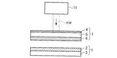
被処理材1に対してドナーシート7が密着されている。ドナーシート7は、基材5と、基材5上に設けられた光熱変換層4及びレジスト層6とを備えている。基材5、レジスト層6、及び光熱変換層4のそれぞれは互いに独立した層として設けられている。レジスト層6は基材5の下面側に設けられ、光熱変換層4も基材5のレジスト層6が設けられた下面側に設けられている。光熱変換層4は、基材5とレジスト層6との間に設けられ、光熱変換層4とレジスト層6とが隣り合っている。そして、ドナーシート7のレジスト層6と被処理材1の被エッチング層2とが対向しており、これらレジスト層6と被エッチング層2とが密着している。 A
ステージ12は、被処理材1及びこの被処理材1に密着したドナーシート7を支持した状態でX軸方向及びY軸方向に移動可能に設けられており、被処理材1及びドナーシート7はステージ12の移動により光源11から射出された光束に対して移動可能となっている。また、ステージ12はZ軸方向にも移動可能となっている。ここで、光源11とステージ12に支持されたドナーシート7との間には不図示の光学系が配置されている。被処理材1及びドナーシート7を支持したステージ12はZ軸方向に移動することにより、前記光学系の焦点に対するドナーシート7(被処理材1)の位置を調整可能となっている。そして、光源11より射出された光束は、ステージ12に支持されているドナーシート7(基材5)を照射するようになっている。 The
基材5としては、レーザ光束を透過可能な例えばガラス基板や透明性高分子等を用いることができる。透明性高分子としては、ポリエチレンテレフタレートのようなポリエステル、ポリアクリル、ポリエポキシ、ポリエチレン、ポリスチレン、ポリカーボネート、ポリサルホン等が挙げられる。透明性高分子により基材5を形成した場合、その厚さは10〜500μmであることが好ましい。こうすることにより、例えば、基材5を帯状に形成してロール状に巻くことができ、回転ドラム等に保持させつつ搬送(移動)することもできる。 As the base material 5, for example, a glass substrate or a transparent polymer that can transmit a laser beam can be used. Examples of the transparent polymer include polyester such as polyethylene terephthalate, polyacryl, polyepoxy, polyethylene, polystyrene, polycarbonate, and polysulfone. When the base material 5 is formed of a transparent polymer, the thickness is preferably 10 to 500 μm. By doing so, for example, the base material 5 can be formed in a band shape and wound in a roll shape, and can also be conveyed (moved) while being held on a rotating drum or the like.
なお、ここでは基材5をXY方向に並進移動するステージ12に支持させているが、基材5を回転ドラムに保持させる場合、回転ドラムは、水平並進方向(走査方向、X方向)、回転方向(Y方向)、及び鉛直方向(Z軸方向)に移動可能である。 Here, the base material 5 is supported by the
光熱変換層4は、光エネルギーを熱エネルギーに変換する光熱変換材料を含んで構成されている。光熱変換層4を構成する光熱変換材料としては公知のものを使用することができ、レーザ光を効率よく熱に変換できる材料であれば特に限定されないが、例えば、アルミニウム、その酸化物及び/又はその硫化物よりなる金属層や、カーボンブラック、黒鉛又は赤外線吸収色素等が添加された高分子よりなる有機層等が挙げられる。赤外線吸収色素としては、アントラキノン系、ジチオールニッケル錯体系、シアニン系、アゾコバルト錯体系、ジインモニウム系、スクワリリウム系、フタロシアニン系、ナフタロシアニン系等が挙げられる。また、エポキシ樹脂等の合成樹脂をバインダとし、そのバインダ樹脂に前記光熱変換材料を溶解又は分散して基材5上に設けるようにしてもよい。この場合、エポキシ樹脂は硬化剤としての機能を有し、硬化させることにより光熱変換層4を基材5上に定着することができる。また、バインダに溶解又は分散せずに、前記光熱変換材料を基材5上に設けることももちろん可能である。 The
光熱変換層4として前記金属層を用いる場合には、真空蒸着法、電子ビーム蒸着法、又はスパッタリングを利用して基材5上に形成することができる。光熱変換層4として前記有機層を用いる場合には、一般的なフィルムコーティング方法、例えば、押出コーティング方法、スピンコーティング方法、グラビアコーティング方法、リバースロールコーティング方法、ロッドコーティング方法、マイクログラビアコーティング方法、ナイフコーティング方法などにより基材5上に形成することができる。光熱変換層4のコーティング方法においては、基材5の表面に帯電した静電気を除電して光熱変換層形成用機能液を均一に基材5に形成するのが好ましく、各方法に用いられる装置には除電装置が取り付けてあるのが好ましい。 When the metal layer is used as the
レジスト層6は、レジスト材料を含んで構成されている。レジスト材料は、後述するエッチング処理において耐エッチング性を有する材料により構成されており、例えばノボラック系樹脂やフェノール系樹脂などの公知の材料を使用することができる。また、レジスト層6は、被エッチング層2に対する転写性(密着性)を有する材料により構成される。レジスト層6は、一般的なフィルムコーティング方法、例えば、押出コーティング方法、スピンコーティング方法、グラビアコーティング方法、リバースロールコーティング方法、ロッドコーティング方法、マイクログラビアコーティング方法などにより、光熱変換層4(基材5)上に形成することができる。レジスト層6のコーティング方法においては、光熱変換層4(基材5)の表面に帯電した静電気を除電してレジスト層形成用機能液を均一に光熱変換層4(基材5)に形成するのが好ましく、各方法に用いられる装置には除電装置が取り付けてあるのが好ましい。 The resist
被処理材1の基板3は、例えばガラスプレートや合成樹脂フィルム、あるいは半導体ウエハにより構成されている。被エッチング層2は、後述するエッチング処理においてエッチングされる層であり、半導体、絶縁物、導電体などの膜により構成されている。 The
次に、図2を参照しながらレジストパターンの形成手順について説明する。図2(a)に示すように、ドナーシート7のレジスト層6と被処理材1の被エッチング層2とを対向した後、密着させる。レジスト層6と被エッチング層2とを密着させるには、レジスト層6と被エッチング層2とを対向させた後、吸引装置13(図1参照)を駆動し、チャンバ14内のガスを吸引してチャンバ14内を減圧する。これにより、レジスト層6と被エッチング層2との間の空間も減圧されて負圧状態となり、レジスト層6と被エッチング層2とが密着される。そして、ドナーシート7(基材5)の上面側から所定の光束径を有するレーザ光束が照射される。レーザ光束が照射されることにより、その照射領域に対応する基材5及び光熱変換層4が加熱される。光熱変換層4は照射されたレーザ光束の光エネルギーを熱エネルギーに変換し、その熱エネルギーを隣接するレジスト層6に供与する。熱エネルギーが供与されたレジスト層6の一部(光熱変換層4との界面付近の一部)は、例えばガラス転移温度以上に加熱されて溶融状態となり、被処理材1の被エッチング層2に転写される。ここで、レジスト層6が転写可能となるのは、レーザ光束の照射領域に対応した領域である。したがって、レーザ光束の照射領域に対応したレジスト層6が被処理材1の被エッチング層2に転写される。 Next, a resist pattern forming procedure will be described with reference to FIG. As shown in FIG. 2A, the resist
そして、照射するレーザ光束に対してステージ12をXY平面に沿って移動することにより、そのステージ12の移動軌跡に応じたレジスト層6の一部が被処理材1に転写される。こうして、被処理材1の被エッチング層2上にレジストパターンが形成される。 Then, by moving the
レジスト層6が被エッチング層2に転写された後、吸引装置13の駆動を解除し、前記減圧状態(負圧状態)を解除することで、図2(b)に示すように、ドナーシート7と被処理材1とが分離可能となる。 After the resist
レジスト層6を被エッチング層2上に転写した後、図2(c)に示すように、エッチング処理が行われる。レジスト層6を形成するレジスト材料は耐エッチング性を有しており、被エッチング層2上に転写されたレジスト層6はエッチングマスクとしての機能を有する。エッチング処理としては、ドライエッチング、ウエットエッチングなど、公知のエッチング処理方法を採用することができる。 After the resist
そして、図2(d)に示すように、被処理材1上のレジスト層6を除去(アッシング)することにより、被エッチング層2はレジストパターンに応じたパターンを形成される。 Then, as shown in FIG. 2D, by removing (ashing) the resist
以上説明したように、基材5上に光熱変換層4を設けたことにより、照射した光の光エネルギーを効率良く熱エネルギーに変換することができる。そして、その熱エネルギーをレジスト層6に供与することで、レジスト層6の光照射領域に対応する部分を被処理材1(被エッチング層2)に転写することができる。したがって、形成しようとするレジストパターンに応じた基材5上の所定領域に対して光を照射することで、その所定領域に応じたレジスト層6のレジスト材料を被処理材1に転写し、被処理材1上に所望のレジストパターンを形成することができる。また、電子ビームや紫外線を用いずに近赤外レーザ光などを用いても、光熱変換層4を設けたことによりレジスト層6を転写するための十分な熱エネルギーをそのレジスト層6に供与することができる。したがって、使用する光照射装置の選択の幅が広がり、高価で大掛かりな光照射装置を用いなくても、十分な熱エネルギーでドナーシート7よりレジスト層6を良好に転写してパターニングすることができる。 As described above, by providing the
そして、本発明では、光照射をするだけで所望のレジストパターンを被処理材1上に形成でき、従来のような現像処理を必要としないため、生産性を向上することができる。また、従来のレジスト材料と異なり、レジスト層に光酸発生剤や光塩基発生剤などを混在させる必要もなく、レジスト材料の主鎖骨格に感光基を組み込む必要もない。すなわち本発明によれば、レジスト材料は被処理材1に対する密着性を有する官能基、耐エッチング性を有する官能基のみを有していればよく、材料設計が容易となる。 In the present invention, a desired resist pattern can be formed on the material to be processed 1 simply by irradiating light, and a conventional development process is not required, so that productivity can be improved. Further, unlike conventional resist materials, it is not necessary to mix a photoacid generator or photobase generator in the resist layer, and it is not necessary to incorporate a photosensitive group into the main chain skeleton of the resist material. That is, according to the present invention, the resist material only needs to have a functional group having adhesion to the
なお本実施形態では、被処理材1及びドナーシート7を支持したステージ12を移動することで、被処理材1(被エッチング層2)上に所定のレジストパターンを形成しているが、もちろん、被処理材1及びドナーシート7を停止した状態で照射する光束を移動するようにしてもよいし、被処理材1及びドナーシート7と光束との双方を移動するようにしてもよい。また、被処理材1及びドナーシート7を移動する場合、ステージ12でXY平面内を移動する構成の他に、上述したように回転ドラムに保持させた状態で移動する構成も可能である。 In the present embodiment, a predetermined resist pattern is formed on the target material 1 (etched layer 2) by moving the
レジストパターンを形成する際、図3に示すように、形成しようとするレジストパターンに応じたパターンを有するマスク15に対して光を照射し、マスク15を介した光をドナーシート7に照射するようにしてもよい。図3に示す例において、マスク15は、マスク15を透過した光を通過するための開口部16Aを有するマスク支持部16に支持されている。光源11から射出された光束は、光学系17により均一な照度分布を有する照明光に変換された後、マスク15を照明する。マスク15を通過した光は、ステージ12に支持されているドナーシート7を照射し、その照射された光に基づいて発生する熱によりレジスト層6の一部が被処理材1に転写され、レジストパターンが形成される。マスク15を用いることにより、レーザ光源11から射出された光束の径より微細なレジストパターンを形成することができる。一方、図1を参照して説明したように、光束とドナーシート7(被処理材1)とを相対移動しつつ光照射することによりマスク15を製造する手間が省ける。 When forming the resist pattern, as shown in FIG. 3, the
なお、図3に示す例では、マスク15とドナーシート7とを離した状態で、ドナーシート7に対して光を照射しているが、マスク15とドナーシート7とを密着させた状態でマスク15に光を照射し、そのマスク15を介した光をドナーシート7に照射するようにしてもよい。 In the example shown in FIG. 3, the
なお、光源11としては、近赤外半導体レーザの他に、水銀ランプ、ハロゲンランプ、キセノンランプ、フラッシュランプなどを用いることも可能である。また、紫外線レーザなど、近赤外線レーザ以外の全ての汎用的なレーザを用いることができる。 As the
なお、上記実施形態において、被処理材1は基板3とその基板3上に設けられた被エッチング層2とを有し、被エッチング層2上にレジスト層6を転写して被エッチング層2をエッチングするように説明したが、被エッチング層2を設けずに、基板3上にレジスト層6を直接転写するようにしてもよい。 In the above embodiment, the
図4に示すように、光熱変換層4を基材5のレジスト層6が設けられていない上面側に設ける構成も可能である。このとき、光熱変換層4より発生した熱エネルギーを下面側に設けたレジスト層6に良好に伝えるために、基材5はその厚さ及び材料を最適に選択される。なお、光熱変換層4を基材5の上面側及び下面側の双方に設けるようにしてもよい。 As shown in FIG. 4, the structure which provides the
光熱変換層4を設けた場合、光熱変換材料に応じた波長を有する光を照射することが好ましい。つまり、使用する光熱変換材料に応じて良好に吸収する光の波長帯域は異なるため、光変換材料に応じた波長を有する光を照射することにより、光エネルギーを熱エネルギーに効率良く変換できる。換言すれば、照射する光に応じて使用する光熱変換材料を選択する。本実施形態では、レーザ光源として近赤外半導体レーザ(波長830nm)を使用しているため、光熱変換材料としては、赤外線〜可視光線領域の光を吸収する性質を有している材料を用いることが好ましい。 When the
なお、上記各実施形態では、光熱変換材料は、基材5及びレジスト層6とは独立した層(光熱変換層4)に設けられているが、基材5に光熱変換材料を混在させる構成も可能であり、レジスト層6に光熱変換材料を混在させる構成も可能である。このような構成であっても、照射したレーザ光の光エネルギーを熱エネルギーに変換し、その熱エネルギーをレジスト層6に供与することができる。なお、光熱変換材料が混在された基材5に、それとは別に光熱変換層4を設けてもよい。 In each of the above embodiments, the photothermal conversion material is provided in a layer (photothermal conversion layer 4) independent from the base material 5 and the resist
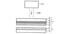
図5に示すように、基材5とレジスト層6との間に、光照射又は加熱によりガスを発生するガス発生材料を含むガス発生層8を設けてもよい。ガス発生材料は、光を吸収したり光エネルギーから変換された熱エネルギーを吸収すると、分解反応を起こして窒素ガスや水素ガスなどを放出するものであって、発生したガスによりレジスト層6を基材5より分離するエネルギーを提供する役割を有する。このようなガス発生材料としては、四窒酸ペンタエリトリトール(pentaerythritol tetranitrate :PETN)及びトリニトロトルエン(trinitrotoluene:TNT)よりなる群から選択された少なくとも一つの物質等が挙げられる。 As shown in FIG. 5, a gas generation layer 8 containing a gas generation material that generates gas by light irradiation or heating may be provided between the base material 5 and the resist
また、図6に示すように、基材5の下面側に光熱変換層4が設けられている構成の場合、光熱変換層4とレジスト層6との間にガス発生層8を設けることもできる。あるいは、基材5と光熱変換層4との間にガス発生層8を設けることもできる。また、光熱変換層4にガス発生材料を混在させてもよい。また、基材5にガス発生材料を混在させてもよい。 As shown in FIG. 6, in the case where the
また、図2等に示す実施形態において、光熱変換層4とレジスト層6との間に、光熱変換層4の光熱変換作用を均一化するための中間層を設けることができる。このような中間層形成材料としては、上記要件を満たすことのできる樹脂材料を挙げることができる。このような中間層は、所定の組成を有する樹脂組成物を例えばスピンコーティング方法、グラビアコーティング方法、ダイコーティング法等の公知のコーティング方法に基づいて光熱変換層4の表面に塗布し、乾燥させることによって形成可能である。レーザ光束が照射されると、光熱変換層4の作用により、光エネルギーが熱エネルギーに変換され、さらにこの熱エネルギーが中間層の作用により均一化される。したがって、光照射領域に該当する部分のレジスト層6には均一な熱エネルギーが供与される。 In the embodiment shown in FIG. 2 and the like, an intermediate layer for making the photothermal conversion action of the
また、図2等に示す実施形態において、光熱変換層4とレジスト層6との間に熱伝播層や剥離層を形成してもよい。熱伝播層や剥離層を構成する材料としては、例えばポリαメチルスチレン酸等が挙げられる。また、熱伝播層及び剥離層は、特に限定されないが、それぞれ1μm程度に形成される。 In the embodiment shown in FIG. 2 and the like, a heat propagation layer or a release layer may be formed between the
また、光熱変換層4とレジスト層6との離型性を向上させるために、光熱変換層4中に離型剤を含有させてもよい。離型剤としては、ポリエチレンワックス、アミドワックス、シリコン系樹脂の微粉末、フッ素系樹脂の微粉末等の固形あるいはワックス状物質;フッ素系、リン酸エステル系等の界面活性剤;パラフィン系、シリコーン系、フッ素系のオイル類等、従来公知の離型剤がいずれも使用できるが、特にシリコーンオイルが好ましい。シリコーンオイルとしては、無変性のもの以外にカルボキシ変性、アミノ変性、エポキシ変性、ポリエーテル変性、アルキル変性等の変性シリコーンオイルを単独あるいは2種以上併用して用いることができる。 Further, a release agent may be contained in the
<配線パターンの形成方法>
以下、被処理材1の基板3上に配線パターンを形成する方法について説明する。図7は、本発明のレジストパターンの形成方法により被エッチング層2上にレジスト層6を転写し、その後、エッチング処理及びアッシング処理することで、基板3上に溝部9を有する被エッチング層2をパターニングし、バンクBを形成した状態を示している。本実施形態では、配線パターン形成用材料を基板3上に配置するために、配線パターン形成用材料を含む機能液の液滴を吐出する液滴吐出法(インクジェット法)を用いる。バンクBは、基板3上に予め設定された配線パターン形成領域を区画するように設けられる。液滴吐出法では、吐出ヘッド20と基板3とを対向させた状態で、バンクB、B間の溝部9に対して配線パターン形成用材料を含む機能液の液滴が吐出ヘッド20より吐出される。<Method for forming wiring pattern>
Hereinafter, a method of forming a wiring pattern on the
ここで、液滴吐出法の吐出技術としては、帯電制御方式、加圧振動方式、電気熱変換方式、静電吸引方式、電気機械変換方式等が挙げられる。帯電制御方式は、材料に帯電電極で電荷を付与し、偏向電極で材料の飛翔方向を制御して吐出ノズルから吐出させるものである。また、加圧振動方式は、材料に30kg/cm2程度の超高圧を印加してノズル先端側に材料を吐出させるものであり、制御電圧をかけない場合には材料が直進して吐出ノズルから吐出され、制御電圧をかけると材料間に静電的な反発が起こり、材料が飛散して吐出ノズルから吐出されない。また、電気熱変換方式は、材料を貯留した空間内に設けたヒータにより、材料を急激に気化させてバブル(泡)を発生させ、バブルの圧力によって空間内の材料を吐出させるものである。静電吸引方式は、材料を貯留した空間内に微小圧力を加え、吐出ノズルに材料のメニスカスを形成し、この状態で静電引力を加えてから材料を引き出すものである。電気機械変換方式は、ピエゾ素子(圧電素子)がパルス的な電気信号を受けて変形する性質を利用したもので、ピエゾ素子が変形することによって材料を貯留した空間に可撓物質を介して圧力を与え、この空間から材料を押し出して吐出ノズルから吐出させるものである。この他に、電場による流体の粘性変化を利用する方式や、放電火花で飛ばす方式などの技術も適用可能である。液滴吐出法は、材料の使用に無駄が少なく、しかも所望の位置に所望の量の材料を的確に配置できるという利点を有する。なお、液滴吐出法により吐出される液体材料の一滴の量は例えば1〜300ナノグラムである。本実施形態では、電気機械変換方式(ピエゾ方式)を用いる。Here, examples of the discharge technique of the droplet discharge method include a charge control method, a pressure vibration method, an electrothermal conversion method, an electrostatic suction method, and an electromechanical conversion method. In the charge control method, a charge is applied to a material with a charging electrode, and the flight direction of the material is controlled with a deflection electrode to be discharged from a discharge nozzle. In addition, the pressure vibration method is a method in which an ultra-high pressure of about 30 kg / cm2 is applied to the material to discharge the material to the nozzle tip side, and when the control voltage is not applied, the material moves straight from the discharge nozzle. When discharged and a control voltage is applied, electrostatic repulsion occurs between the materials, and the materials are scattered and are not discharged from the discharge nozzle. In the electrothermal conversion method, a material is rapidly vaporized by a heater provided in a space in which the material is stored to generate bubbles, and the material in the space is discharged by the pressure of the bubbles. In the electrostatic attraction method, a minute pressure is applied to a space in which a material is stored, a meniscus of material is formed on the discharge nozzle, and an electrostatic attractive force is applied in this state before the material is drawn out. The electromechanical conversion method utilizes the property that a piezo element (piezoelectric element) deforms in response to a pulsed electric signal, and the piezoelectric element is deformed by pressure through a flexible substance in a space where material is stored. The material is extruded from this space and discharged from the discharge nozzle. In addition to this, it is also possible to apply a technique such as a method using the viscosity change of a fluid due to an electric field or a method using a discharge spark. The droplet discharge method has an advantage that the use of the material is less wasteful and a desired amount of the material can be accurately disposed at a desired position. In addition, the amount of one drop of the liquid material discharged by the droplet discharge method is 1 to 300 nanograms, for example. In this embodiment, an electromechanical conversion method (piezo method) is used.
図8はピエゾ方式による機能液(液状体材料)の吐出原理を説明するための図である。図8において、吐出ヘッド20は、機能液(配線パターン形成用材料を含む液状体材料)を収容する液体室21と、その液体室21に隣接して設置されたピエゾ素子22とを備えている。液体室21には、機能液を収容する材料タンクを含む供給系23を介して機能液が供給される。ピエゾ素子22は駆動回路24に接続されており、この駆動回路24を介してピエゾ素子22に電圧を印加し、ピエゾ素子22を変形させることにより、液体室21が変形し、吐出ノズル25から機能液が吐出される。この場合、印加電圧の値を変化させることによりピエゾ素子22の歪み量が制御される。また、印加電圧の周波数を変化させることによりピエゾ素子22の歪み速度が制御される。ピエゾ方式による液滴吐出は材料に熱を加えないため、材料の組成に影響を与えにくいという利点を有する。 FIG. 8 is a diagram for explaining the discharge principle of the functional liquid (liquid material) by the piezo method. In FIG. 8, the
以下、配線パターンを形成する手順について説明する。上記説明した方法によりバンクB、Bを形成した後、まず、バンクB、B間の溝部9の底部9B(基板3の露出部)の残渣を除去する残渣処理を行うことが好ましい。残渣処理としては、溝部9の底部9Bに対して例えば紫外線(UV)等の光を照射することにより、光励起により、底部9Bに残存する特に有機系の残渣を良好に除去することができる。なお、残渣処理としては、所定の処理ガスとして例えば酸素(O2)を含む処理ガスを用いたO2プラズマ処理によっても残渣を除去することができる。また、紫外線照射処理やO2プラズマ処理は底部9B(基板3の露出部)に対して親液性を付与する親液化処理としての役割も有し、底部9B(基板3の露出部)に親液性を付与することで後述するように機能液の液滴を溝部9に配置したとき、その機能液を底部9Bに良好に濡れ拡がらせることができる。Hereinafter, a procedure for forming a wiring pattern will be described. After the banks B and B are formed by the above-described method, it is preferable to first perform a residue treatment for removing the residue at the bottom 9B (exposed portion of the substrate 3) of the
続いて、バンクBに対し撥液化処理を行い、その表面に撥液性を付与する。撥液化処理としては、例えば大気雰囲気中でテトラフルオロメタンを処理ガスとするプラズマ処理法(CF4プラズマ処理法)を採用することができる。なお、処理ガスとしては、テトラフルオロメタン(四フッ化炭素)に限らず、他のフルオロカーボン系のガスを用いることもできる。更に、機能液に対する撥液性を付与可能なものであれば、フッ素系以外の処理ガスを用いてもよい。また、撥液化処理としては、FAS(フルオロアルキルシラン)で処理する方法(自己組織化膜法、化学気相蒸着法等)や、共役メッキ法、あるいは金チオールで撥液化する方法など、公知の様々な方法を採用することができる。バンクBに撥液性を付与することにより、吐出ヘッド20より吐出された液滴の一部がバンクBの上面9Aに乗っても、バンク表面が撥液性となっていることによりバンクBからはじかれ、バンクB、B間の溝部9に流れ落ちるようになる。したがって、吐出された機能液は基板3上のバンクB、B間に良好に配置される。Subsequently, the bank B is subjected to a liquid repellency treatment to impart liquid repellency to the surface thereof. As the lyophobic treatment, for example, a plasma treatment method (CF4 plasma treatment method) using tetrafluoromethane as a treatment gas in an air atmosphere can be employed. The processing gas is not limited to tetrafluoromethane (carbon tetrafluoride), and other fluorocarbon gases can also be used. Furthermore, a treatment gas other than fluorine-based gas may be used as long as it can impart liquid repellency to the functional liquid. Further, as the liquid repellent treatment, there are known methods such as a method of treating with FAS (fluoroalkylsilane) (self-organized film method, chemical vapor deposition method, etc.), a conjugate plating method, or a method of repelling liquid with gold thiol. Various methods can be employed. By imparting liquid repellency to the bank B, even if some of the liquid droplets ejected from the
なお、バンクB、Bに対する撥液化処理により、先に親液化処理したバンク間の底部9B(基板3の露出部)に対し多少は影響があるものの、特に基板3がガラス等からなる場合には、撥液化処理によるフッ素基の導入が起こらないため、基板3はその親液性を実質上損なわれない。また、バンクB(被エッチング層2)に予め撥液性を有する調整材料を混在させておくことにより、この撥液化処理工程を省略することが可能である。 Note that the lyophobic treatment for the banks B and B has some influence on the
次に、吐出ヘッド20を用いて、基板3上のバンクB、B間に配線パターン形成用材料を含む機能液の液滴を配置する材料配置工程が行われる。ここでは、配線パターン形成用材料を構成する導電性材料として有機銀化合物を用い、溶媒(分散媒)としてジエチレングリコールジエチルエーテルを用い、その有機銀化合物を含む機能液を吐出する。材料配置工程では、図7に示したように、吐出ヘッド20から配線パターン形成用材料を含む機能液を液滴にして吐出する。吐出された液滴は、基板3上のバンクB、B間の溝部9に配置される。このとき、液滴が吐出される配線パターン形成領域はバンクBにより区画されているので、液滴が所定位置以外に拡がることを阻止できる。また、バンクB、Bには撥液性が付与されているため、吐出された液滴の一部がバンクB上に乗ってもバンク間の溝部9に流れ落ちるようになる。更に、基板3が露出している溝部9の底部9Bは親液性を付与されているため、吐出された液滴が底部9Bにてより拡がり易くなり、これにより機能液は所定位置内で均一に配置される。 Next, a material disposing step is performed in which the droplets of the functional liquid including the wiring pattern forming material are disposed between the banks B and B on the
なお、機能液としては、導電性微粒子を分散媒に分散した分散液を用いることも可能である。導電性微粒子としては、例えば、金、銀、銅、アルミニウム、パラジウム、及びニッケルのうちの少なくともいずれか1つを含有する金属微粒子の他、これらの酸化物、並びに導電性ポリマーや超電導体の微粒子などが用いられる。分散媒としては、上記の導電性微粒子を分散できるもので凝集を起こさないものであれば特に限定されない。例えば、水の他に、メタノール、エタノール、プロパノール、ブタノールなどのアルコール類、n−ヘプタン、n−オクタン、デカン、ドデカン、テトラデカン、トルエン、キシレン、シメン、デュレン、インデン、ジペンテン、テトラヒドロナフタレン、デカヒドロナフタレン、シクロヘキシルベンゼンなどの炭化水素系化合物、またエチレングリコールジメチルエーテル、エチレングリコールジエチルエーテル、エチレングリコールメチルエチルエーテル、ジエチレングリコールジメチルエーテル、ジエチレングリコールジエチルエーテル、ジエチレングリコールメチルエチルエーテル、1,2−ジメトキシエタン、ビス(2−メトキシエチル)エーテル、p−ジオキサンなどのエーテル系化合物、さらにプロピレンカーボネート、γ−ブチロラクトン、N−メチル−2−ピロリドン、ジメチルホルムアミド、ジメチルスルホキシド、シクロヘキサノンなどの極性化合物を例示できる。これらのうち、微粒子の分散性と分散液の安定性、また液滴吐出法への適用の容易さの点で、水、アルコール類、炭化水素系化合物、エーテル系化合物が好ましく、より好ましい分散媒としては、水、炭化水素系化合物を挙げることができる。 As the functional liquid, it is also possible to use a dispersion liquid in which conductive fine particles are dispersed in a dispersion medium. Examples of the conductive fine particles include metal fine particles containing at least one of gold, silver, copper, aluminum, palladium, and nickel, oxides thereof, and fine particles of conductive polymers and superconductors. Etc. are used. The dispersion medium is not particularly limited as long as it can disperse the conductive fine particles and does not cause aggregation. For example, in addition to water, alcohols such as methanol, ethanol, propanol, butanol, n-heptane, n-octane, decane, dodecane, tetradecane, toluene, xylene, cymene, durene, indene, dipentene, tetrahydronaphthalene, decahydro Hydrocarbon compounds such as naphthalene and cyclohexylbenzene, ethylene glycol dimethyl ether, ethylene glycol diethyl ether, ethylene glycol methyl ethyl ether, diethylene glycol dimethyl ether, diethylene glycol diethyl ether, diethylene glycol methyl ethyl ether, 1,2-dimethoxyethane, bis (2- Methoxyethyl) ether, ether compounds such as p-dioxane, propylene carbonate, γ- Butyrolactone, N- methyl-2-pyrrolidone, dimethylformamide, dimethyl sulfoxide, can be exemplified polar compounds such as cyclohexanone. Of these, water, alcohols, hydrocarbon compounds, and ether compounds are preferable and more preferable dispersion media in terms of fine particle dispersibility, dispersion stability, and ease of application to the droplet discharge method. Examples thereof include water and hydrocarbon compounds.
材料配置工程(液滴吐出工程)の後、焼成工程が行われる。導電性材料を含む機能液に対して焼成処理を行うことにより導電性が得られる。特に有機銀化合物の場合、焼成処理を行ってその有機分を除去し銀粒子を残留させることで導電性が発現される。そのため、材料配置工程後の基板3に対して、焼成処理として熱処理及び光処理のうちの少なくとも一方が施される。熱処理・光処理は通常大気中で行なわれるが、必要に応じて、窒素、アルゴン、ヘリウムなどの不活性ガス雰囲気中で行なうこともできる。熱処理・光処理の処理温度は、溶媒の沸点(蒸気圧)、雰囲気ガスの種類や圧力、微粒子の分散性や有機銀化合物、酸化性等の熱的挙動、コーティング材の有無や量、基材の耐熱温度などを考慮して適宜決定される。たとえば、有機銀化合物の有機分を除去するためには、約200℃で焼成することが必要である。また、プラスチックなどの基板を使用する場合には、室温以上100℃以下で行なうことが好ましい。以上の工程により吐出工程後の導電性材料(有機銀化合物)は、銀粒子の残留により、導電性を有する配線パターンに変換される。 A firing process is performed after a material arrangement process (droplet discharge process). Conductivity is obtained by performing a baking treatment on the functional liquid containing the conductive material. In particular, in the case of an organic silver compound, conductivity is developed by performing a baking treatment to remove the organic component and leave silver particles. Therefore, at least one of heat treatment and light treatment is performed as the baking treatment on the
なお、材料配置工程の後、中間乾燥工程(あるいは焼成工程)を行い、これら材料配置工程と中間乾燥工程(焼成工程)とを交互に複数回繰り返すことにより、配線パターン形成用材料をバンクB、B間で積層することができる。 After the material placement step, an intermediate drying step (or firing step) is performed, and the material placement step and the intermediate drying step (baking step) are alternately repeated a plurality of times, whereby the wiring pattern forming material is changed to bank B, It can be laminated between B.
なお、焼成工程の後、基板3上に存在するバンクBを除去することができる。例えば、所定の溶剤により洗浄することでバンクBを基板3から除去することができる。 Note that the bank B existing on the
<プラズマ表示装置>
次に、本発明の配線パターンの形成方法により形成された配線パターンを有する電気光学装置の一例として、プラズマディスプレイ(プラズマ表示装置)について図9を参照しながら説明する。図9は、アドレス電極511とバス電極512aとが製造されたプラズマディスプレイ500を示す分解斜視図である。このプラズマディスプレイ500は、互いに対向して配置されたガラス基板501とガラス基板502と、これらの間に形成された放電表示部510とから概略構成されている。<Plasma display device>
Next, as an example of an electro-optical device having a wiring pattern formed by the wiring pattern forming method of the present invention, a plasma display (plasma display device) will be described with reference to FIG. FIG. 9 is an exploded perspective view showing the
放電表示部510は、複数の放電室516が集合されてなり、複数の放電室516のうち、赤色放電室516(R)、緑色放電室516(G)、青色放電室516(B)の3つの放電室516が対になって1画素を構成するように配置されている。前記(ガラス)基板501の上面には所定の間隔でストライプ状にアドレス電極511が形成され、それらアドレス電極511と基板501の上面とを覆うように誘電体層519が形成され、さらに誘電体層519上においてアドレス電極511、511間に位置して各アドレス電極511に沿うように隔壁515が形成されている。なお、隔壁515においてはその長手方向の所定位置においてアドレス電極511と直交する方向にも所定の間隔で仕切られており(図示略)、基本的にはアドレス電極511の幅方向左右両側に隣接する隔壁と、アドレス電極511と直交する方向に延設された隔壁により仕切られる長方形状の領域が形成され、これら長方形状の領域に対応するように放電室516が形成され、これら長方形状の領域が3つ対になって1画素が構成される。また、隔壁515で区画される長方形状の領域の内側には蛍光体517が配置されている。蛍光体517は、赤、緑、青の何れかの蛍光を発光するもので、赤色放電室516(R)の底部には赤色蛍光体517(R)が、緑色放電室516(G)の底部には緑色蛍光体517(G)が、青色放電室516(B)の底部には青色蛍光体517(B)が各々配置されている。 The
次に、前記ガラス基板502側には、先のアドレス電極511と直交する方向に複数のITOからなる透明表示電極512がストライプ状に所定の間隔で形成されるとともに、高抵抗のITOを補うために金属からなるバス電極512aが形成されている。また、これらを覆って誘電体層513が形成され、さらにMgOなどからなる保護膜514が形成されている。そして、前記基板501とガラス基板502の基板2が、前記アドレス電極511…と表示電極512…を互いに直交させるように対向させて相互に貼り合わされ、基板501と隔壁515とガラス基板502側に形成されている保護膜514とで囲まれる空間部分を排気して希ガスを封入することで放電室516が形成されている。なお、ガラス基板502側に形成される表示電極512は各放電室516に対して2本ずつ配置されるように形成されている。 前記アドレス電極511と表示電極512は図示略の交流電源に接続され、各電極に通電することで必要な位置の放電表示部510において蛍光体517を励起発光させて、カラー表示ができるようになっている。 Next, on the
そして、本例では、特に前記アドレス電極511とバス電極512aとが、本発明に係る配線パターンの形成方法により形成される。すなわち、これらアドレス電極511やバス電極512aについては、特にそのパターニングに有利なことから、金属コロイド材料(例えば金コロイドや銀コロイド)や導電性微粒子(例えば金属微粒子)を分散させてなる機能液を吐出し、乾燥・焼成することによって形成している。また、蛍光体517についても、蛍光体材料を溶媒に溶解させあるいは分散媒に分散させた機能液を吐出ヘッド20より吐出し、乾燥・焼成することによって形成可能である。 In this example, the
<薄膜トランジスタ>
次に、本発明に係るレジストパターンを使って半導体素子を形成する一例として、薄膜トランジスタを形成する手順について、図10を参照しながら説明する。図10(a)に示すように、ゲート電極402が形成された基板401上に、ゲート絶縁層403、ドープしていないアモルファスシリコンからなる活性半導体層であるa-Si層404、リン等を高濃度でドープしたシリコンからなるN+a-Si層405、ソース/ドレイン電極形成用金属層406が順次積層され、ソース/ドレイン電極形成用金属層406上の一部に、本発明に係るレジストパターンの形成方法によりレジスト層407がパターニングされる。次いで、図10(b)に示すように、a-Si層404、N+a-Si層405、及びソース/ドレイン電極形成用金属層406がエッチングされ、図10(c)に示すように、レジスト層407がアッシングされる。次に、図10(d)に示すように、再びレジスト層407が本発明に係るレジストパターンの形成方法に基づいて設けられる。そして、図10(e)に示すように、薄膜トランジスタのチャネル部408に対応する部分のN+a-Si層405、及びソース/ドレイン電極形成用金属層406がエッチングされ、レジスト層407をアッシングすることで、図10(f)に示すように、チャネル部408、ソース電極409、及びドレイン電極410が形成される。そして、ドレイン電極410に接続する不図示の画素電極を形成することで薄膜トランジスタが形成される。<Thin film transistor>
Next, as an example of forming a semiconductor element using the resist pattern according to the present invention, a procedure for forming a thin film transistor will be described with reference to FIG. As shown in FIG. 10A, a
<有機EL表示装置>
次に、上記薄膜トランジスタ(半導体素子)を有する電気光学装置の一例として、有機EL(エレクトロルミネッセンス)表示装置について図11を参照しながら説明する。
図11において、有機EL表示装置601は、光を透過可能な基板(光透過層)602と、基板602の一方の面側に設けられ一対の電極(陽極604及び陰極607)に挟持された有機エレクトロルミネッセンス材料からなる発光層(EL層)606と正孔注入/輸送層605とからなる有機EL素子(発光素子)603と、基板602の一方の面側に設けられ、陽極(画素電極)604に接続する薄膜トランジスタTFTと、封止基板612とを有している。発光層606は赤色(R)、緑色(G)、及び青色(B)の3色の発光層により構成されている。また、封止基板612と基板602とは接着層で接着されており、封止基板612及び接着層により有機EL素子603が封止されている。ここで、図11に示す有機EL表示装置601は発光層606からの発光を基板602側から装置外部に取り出す形態(ボトムエミッション型、基板側発光型)である。<Organic EL display device>
Next, as an example of an electro-optical device having the thin film transistor (semiconductor element), an organic EL (electroluminescence) display device will be described with reference to FIG.
In FIG. 11, an organic
基板602の形成材料としては、光を透過可能な透明あるいは半透明材料、例えば、透明なガラス、石英、サファイア、あるいはポリエステル、ポリアクリレート、ポリカーボネート、ポリエーテルケトンなどの透明な合成樹脂などが挙げられる。特に、基板602の形成材料としては、安価なガラスが好適に用いられる。 As a material for forming the
封止基板612としては、例えばガラス基板を用いるが、透明でガスバリア性に優れていれば例えば、プラスチック、プラスチックのラミネートフィルム、ラミネート成型基板等のガラス基板以外の部材、またはガラスのラミネートフィルム等を用いてもよい。また、保護層として紫外線を吸収する部材を用いることも好ましい。 As the sealing
陽極(画素電極)604は、インジウム錫酸化物(ITO:Indium Tin Oxide)等からなる透明電極であって光を透過可能である。正孔注入/輸送層605は、例えば、高分子系材料として、ポリチオフェン、ポリスチレンスルホン酸、ポリピロール、ポリアニリン及びこの誘導体などが例示される。発光層606の形成材料としては、高分子発光体や低分子の有機発光色素、すなわち各種の蛍光物質や燐光物質などの発光物質が使用可能である。発光物質となる共役系高分子の中ではアリーレンビニレン又はポリフルオレン構造を含むものなどが特に好ましい。なお、陰極607と発光層606との間に、必要に応じて電子輸送層や電子注入層を設けてもよい。 The anode (pixel electrode) 604 is a transparent electrode made of indium tin oxide (ITO) or the like, and can transmit light. Examples of the hole injection /
有機EL素子603は、バンク614によって区画された領域に配置されており、この有機EL素子603を形成する際に、前記吐出ヘッド20を用いている。 The
図示はしないが、本実施形態の有機EL表示装置601はアクティブマトリクス型であり、実際には複数のデータ線と複数の走査線とが格子状に基板602に配置される。そして、データ線や走査線に区画されたマトリクス状に配置された各画素毎に、スイッチングトランジスタやドライビングトランジスタ等の駆動用TFTを介して上記の有機EL素子603が接続されている。そして、データ線や走査線を介して駆動信号が供給されると電極間に電流が流れ、有機EL素子603の発光層606が発光して基板602の外面側に光が射出され、その画素が点灯する。 Although not shown, the organic
なおここでは、薄膜トランジスタを有機EL表示装置に適用した例を説明したが、もちろん、液晶表示装置など、スイッチング素子を有する他の表示装置に、本発明に係る薄膜トランジスタを適用することができる。 Although an example in which the thin film transistor is applied to an organic EL display device has been described here, it is needless to say that the thin film transistor according to the present invention can be applied to another display device having a switching element such as a liquid crystal display device.
<電子機器>
以下、上記電気光学装置(有機EL表示装置、プラズマ表示装置、液晶表示装置等)を備えた電子機器の適用例について説明する。図12(a)は、携帯電話の一例を示した斜視図である。図12(a)において、符号1000は携帯電話本体を示し、符号1001は上記の電気光学装置を用いた表示部を示している。図12(b)は、腕時計型電子機器の一例を示した斜視図である。図12(b)において、符号1100は時計本体を示し、符号1101は上記の電気光学装置を用いた表示部を示している。図12(c)は、ワープロ、パソコンなどの携帯型情報処理装置の一例を示した斜視図である。図12(c)において、符号1200は情報処理装置、符号1202はキーボードなどの入力部、符号1204は情報処理装置本体、符号1206は上記の電気光学装置を用いた表示部を示している。図12(a)〜(c)に示す電子機器は、上記実施の形態の電気光学装置を備えているので、表示品位に優れ、明るい画面の表示部を備えた電子機器を実現することができる。<Electronic equipment>
Hereinafter, application examples of an electronic apparatus provided with the electro-optical device (organic EL display device, plasma display device, liquid crystal display device, etc.) will be described. FIG. 12A is a perspective view showing an example of a mobile phone. In FIG. 12A,
なお、上述した例に加えて、他の例として、液晶テレビ、ビューファインダ型やモニタ直視型のビデオテープレコーダ、カーナビゲーション装置、ページャ、電子手帳、電卓、ワードプロセッサ、ワークステーション、テレビ電話、POS端末、電子ペーパー、タッチパネルを備えた機器等が挙げられる。本発明の電気光学装置は、こうした電子機器の表示部としても適用できる。 In addition to the above-described examples, other examples include a liquid crystal television, a viewfinder type and a monitor direct-view type video tape recorder, a car navigation device, a pager, an electronic notebook, a calculator, a word processor, a workstation, a videophone, and a POS terminal. , Electronic paper, devices equipped with a touch panel, and the like. The electro-optical device of the present invention can also be applied as a display unit of such an electronic apparatus.
1…被処理材、2…被エッチング層、4…光熱変換層、5…基材、6…レジスト層、
7…ドナーシート、8…ガス発生層、11…光源、13…吸引装置、15…マスクDESCRIPTION OF
7 ... Donor sheet, 8 ... Gas generating layer, 11 ... Light source, 13 ... Suction device, 15 ... Mask
Claims (20)
Translated fromJapanesePriority Applications (5)
| Application Number | Priority Date | Filing Date | Title |
|---|---|---|---|
| JP2003290658AJP2005064143A (en) | 2003-08-08 | 2003-08-08 | Resist pattern forming method, wiring pattern forming method, semiconductor device manufacturing method, electro-optical device, and electronic apparatus |
| US10/902,147US20050074705A1 (en) | 2003-08-08 | 2004-07-30 | Method of forming a resist pattern, method of forming a wiring pattern, method of fabricating a semiconductor device, electro-optic device, and electronic apparatus |
| TW093123392ATWI285800B (en) | 2003-08-08 | 2004-08-04 | Method for forming photoresist pattern, method for forming wiring pattern, method for making semiconductor devices, electro-optical device and electronic apparatus |
| CNB2004100558993ACN100375239C (en) | 2003-08-08 | 2004-08-05 | Method for forming resist pattern and wiring pattern, method for manufacturing semiconductor device |
| KR1020040062067AKR20050019024A (en) | 2003-08-08 | 2004-08-06 | Method of forming resist pattern and method of forming wiring pattern, method of manufacturing semiconductor device, electrooptical device and electronic apparatus |
Applications Claiming Priority (1)
| Application Number | Priority Date | Filing Date | Title |
|---|---|---|---|
| JP2003290658AJP2005064143A (en) | 2003-08-08 | 2003-08-08 | Resist pattern forming method, wiring pattern forming method, semiconductor device manufacturing method, electro-optical device, and electronic apparatus |
Publications (1)
| Publication Number | Publication Date |
|---|---|
| JP2005064143Atrue JP2005064143A (en) | 2005-03-10 |
Family
ID=34368624
Family Applications (1)
| Application Number | Title | Priority Date | Filing Date |
|---|---|---|---|
| JP2003290658AWithdrawnJP2005064143A (en) | 2003-08-08 | 2003-08-08 | Resist pattern forming method, wiring pattern forming method, semiconductor device manufacturing method, electro-optical device, and electronic apparatus |
Country Status (5)
| Country | Link |
|---|---|
| US (1) | US20050074705A1 (en) |
| JP (1) | JP2005064143A (en) |
| KR (1) | KR20050019024A (en) |
| CN (1) | CN100375239C (en) |
| TW (1) | TWI285800B (en) |
Cited By (14)
| Publication number | Priority date | Publication date | Assignee | Title |
|---|---|---|---|---|
| KR100676520B1 (en) | 2005-10-24 | 2007-02-01 | 삼성전자주식회사 | Photoresist Pattern Formation Method |
| WO2007097112A1 (en)* | 2006-02-23 | 2007-08-30 | Fujifilm Corporation | Multilayer material, method of forming resin pattern, substrate, display apparatus and liquid crystal display apparatus |
| JP2007223181A (en)* | 2006-02-23 | 2007-09-06 | Fujifilm Corp | Multilayer material, resin pattern forming method, substrate, display device, and liquid crystal display device |
| JP2007225939A (en)* | 2006-02-23 | 2007-09-06 | Fujifilm Corp | Multilayer material, resin pattern forming method, substrate, display device, and liquid crystal display device |
| KR100770274B1 (en) | 2007-06-13 | 2007-10-26 | 삼성에스디아이 주식회사 | Pattern formation method of resist |
| JP2009510521A (en)* | 2005-09-30 | 2009-03-12 | イーストマン コダック カンパニー | Laser resist transfer for micro assembly |
| WO2010005032A1 (en)* | 2008-07-09 | 2010-01-14 | 東洋合成工業株式会社 | Pattern-forming method |
| JP2010103464A (en)* | 2008-09-26 | 2010-05-06 | Toshiba Corp | Imprint method |
| JP2010522102A (en)* | 2007-03-22 | 2010-07-01 | スリーエム イノベイティブ プロパティズ カンパニー | Microreplication tools and patterns using laser-induced hot embossing |
| JP2010262980A (en)* | 2009-04-30 | 2010-11-18 | Jsr Corp | Curable composition for nanoimprint lithography and nanoimprint method |
| JP4913750B2 (en)* | 2005-11-21 | 2012-04-11 | 富士フイルム株式会社 | Photosensitive transfer material, partition wall and method for forming the same, optical element and method for manufacturing the same, and display device |
| WO2013062068A1 (en)* | 2011-10-24 | 2013-05-02 | Canon Kabushiki Kaisha | Method of forming film |
| JP2018054665A (en)* | 2016-09-26 | 2018-04-05 | カンタツ株式会社 | Pattern forming sheet, pattern manufacturing device, pattern manufacturing method, and pattern manufacturing program |
| JP2018207128A (en)* | 2018-09-12 | 2018-12-27 | 東芝メモリ株式会社 | Template, template base material, template forming method, and semiconductor device manufacturing method |
Families Citing this family (6)
| Publication number | Priority date | Publication date | Assignee | Title |
|---|---|---|---|---|
| US8097400B2 (en)* | 2005-02-22 | 2012-01-17 | Hewlett-Packard Development Company, L.P. | Method for forming an electronic device |
| JP2006332592A (en) | 2005-04-28 | 2006-12-07 | Ricoh Co Ltd | Electrical component, method for forming conductive pattern, and inkjet head |
| US7867688B2 (en)* | 2006-05-30 | 2011-01-11 | Eastman Kodak Company | Laser ablation resist |
| JP2009130180A (en)* | 2007-11-26 | 2009-06-11 | Sony Corp | Electronic device manufacturing method and electronic device |
| JP5848320B2 (en)* | 2013-12-20 | 2016-01-27 | デクセリアルズ株式会社 | Cylindrical substrate, master, and method for manufacturing master |
| CN107301973B (en)* | 2017-06-29 | 2021-04-13 | 惠科股份有限公司 | A manufacturing method of an array substrate and a display device |
Family Cites Families (19)
| Publication number | Priority date | Publication date | Assignee | Title |
|---|---|---|---|---|
| US5256506A (en)* | 1990-10-04 | 1993-10-26 | Graphics Technology International Inc. | Ablation-transfer imaging/recording |
| JPH04327982A (en)* | 1991-04-26 | 1992-11-17 | Fuji Photo Film Co Ltd | Image forming method |
| US5278023A (en)* | 1992-11-16 | 1994-01-11 | Minnesota Mining And Manufacturing Company | Propellant-containing thermal transfer donor elements |
| JPH06347637A (en)* | 1993-06-14 | 1994-12-22 | Dainippon Ink & Chem Inc | Printing method |
| US5691098A (en)* | 1996-04-03 | 1997-11-25 | Minnesota Mining And Manufacturing Company | Laser-Induced mass transfer imaging materials utilizing diazo compounds |
| US5800723A (en)* | 1996-12-10 | 1998-09-01 | Motorola, Inc. | Process for fabricating flex circuits and product thereby |
| KR100195175B1 (en)* | 1996-12-23 | 1999-06-15 | 손욱 | Electroluminescence element and its manufacturing method |
| JP2000137322A (en)* | 1998-10-30 | 2000-05-16 | Fuji Photo Film Co Ltd | Waterless lithographic printing master plate and forming method of waterless lithographic printing plate |
| US6114088A (en)* | 1999-01-15 | 2000-09-05 | 3M Innovative Properties Company | Thermal transfer element for forming multilayer devices |
| US6461775B1 (en)* | 1999-05-14 | 2002-10-08 | 3M Innovative Properties Company | Thermal transfer of a black matrix containing carbon black |
| US6228543B1 (en)* | 1999-09-09 | 2001-05-08 | 3M Innovative Properties Company | Thermal transfer with a plasticizer-containing transfer layer |
| US6242152B1 (en)* | 2000-05-03 | 2001-06-05 | 3M Innovative Properties | Thermal transfer of crosslinked materials from a donor to a receptor |
| US6358664B1 (en)* | 2000-09-15 | 2002-03-19 | 3M Innovative Properties Company | Electronically active primer layers for thermal patterning of materials for electronic devices |
| US6743556B2 (en)* | 2001-08-09 | 2004-06-01 | Creo Srl | Method for accurate placement of fluid materials on a substrate |
| US6588370B1 (en)* | 2001-10-03 | 2003-07-08 | The United States Of America As Represented By The Secretary Of The Interior | Labyrinth weir and pool fishway |
| US6555284B1 (en)* | 2001-12-27 | 2003-04-29 | Eastman Kodak Company | In situ vacuum method for making OLED devices |
| JP2003215816A (en)* | 2002-01-22 | 2003-07-30 | Fuji Photo Film Co Ltd | Conductive pattern material and method for forming conductive pattern |
| US6703179B2 (en)* | 2002-03-13 | 2004-03-09 | Eastman Kodak Company | Transfer of organic material from a donor to form a layer in an OLED device |
| US6929048B2 (en)* | 2003-09-05 | 2005-08-16 | Eastman Kodak Company | Laser transfer of organic material from a donor to form a layer in an OLED device |
- 2003
- 2003-08-08JPJP2003290658Apatent/JP2005064143A/ennot_activeWithdrawn
- 2004
- 2004-07-30USUS10/902,147patent/US20050074705A1/ennot_activeAbandoned
- 2004-08-04TWTW093123392Apatent/TWI285800B/ennot_activeIP Right Cessation
- 2004-08-05CNCNB2004100558993Apatent/CN100375239C/ennot_activeExpired - Fee Related
- 2004-08-06KRKR1020040062067Apatent/KR20050019024A/ennot_activeCeased
Cited By (16)
| Publication number | Priority date | Publication date | Assignee | Title |
|---|---|---|---|---|
| JP2009510521A (en)* | 2005-09-30 | 2009-03-12 | イーストマン コダック カンパニー | Laser resist transfer for micro assembly |
| KR100676520B1 (en) | 2005-10-24 | 2007-02-01 | 삼성전자주식회사 | Photoresist Pattern Formation Method |
| JP4913750B2 (en)* | 2005-11-21 | 2012-04-11 | 富士フイルム株式会社 | Photosensitive transfer material, partition wall and method for forming the same, optical element and method for manufacturing the same, and display device |
| WO2007097112A1 (en)* | 2006-02-23 | 2007-08-30 | Fujifilm Corporation | Multilayer material, method of forming resin pattern, substrate, display apparatus and liquid crystal display apparatus |
| JP2007223181A (en)* | 2006-02-23 | 2007-09-06 | Fujifilm Corp | Multilayer material, resin pattern forming method, substrate, display device, and liquid crystal display device |
| JP2007225939A (en)* | 2006-02-23 | 2007-09-06 | Fujifilm Corp | Multilayer material, resin pattern forming method, substrate, display device, and liquid crystal display device |
| JP2010522102A (en)* | 2007-03-22 | 2010-07-01 | スリーエム イノベイティブ プロパティズ カンパニー | Microreplication tools and patterns using laser-induced hot embossing |
| KR100770274B1 (en) | 2007-06-13 | 2007-10-26 | 삼성에스디아이 주식회사 | Pattern formation method of resist |
| WO2010005032A1 (en)* | 2008-07-09 | 2010-01-14 | 東洋合成工業株式会社 | Pattern-forming method |
| JP2010103464A (en)* | 2008-09-26 | 2010-05-06 | Toshiba Corp | Imprint method |
| US8419995B2 (en) | 2008-09-26 | 2013-04-16 | Kabushiki Kaisha Toshiba | Imprint method |
| JP2010262980A (en)* | 2009-04-30 | 2010-11-18 | Jsr Corp | Curable composition for nanoimprint lithography and nanoimprint method |
| WO2013062068A1 (en)* | 2011-10-24 | 2013-05-02 | Canon Kabushiki Kaisha | Method of forming film |
| US9623439B2 (en) | 2011-10-24 | 2017-04-18 | Canon Kabushiki Kaisha | Method of forming film |
| JP2018054665A (en)* | 2016-09-26 | 2018-04-05 | カンタツ株式会社 | Pattern forming sheet, pattern manufacturing device, pattern manufacturing method, and pattern manufacturing program |
| JP2018207128A (en)* | 2018-09-12 | 2018-12-27 | 東芝メモリ株式会社 | Template, template base material, template forming method, and semiconductor device manufacturing method |
Also Published As
| Publication number | Publication date |
|---|---|
| TWI285800B (en) | 2007-08-21 |
| TW200506555A (en) | 2005-02-16 |
| CN1581436A (en) | 2005-02-16 |
| KR20050019024A (en) | 2005-02-28 |
| CN100375239C (en) | 2008-03-12 |
| US20050074705A1 (en) | 2005-04-07 |
Similar Documents
| Publication | Publication Date | Title |
|---|---|---|
| KR100613160B1 (en) | Method for forming film, method for forming wiring pattern, and method for manufacturing semiconductor device | |
| JP2005064143A (en) | Resist pattern forming method, wiring pattern forming method, semiconductor device manufacturing method, electro-optical device, and electronic apparatus | |
| JP4400138B2 (en) | Method for forming wiring pattern | |
| CN1331191C (en) | Pattern formation method and pattern formation apparatus, method for manufacturing device, electro-optical device, | |
| KR100690547B1 (en) | Forming method of thin film pattern and manufacturing method of device, electro-optical device and electronic device | |
| CN1592528B (en) | Conductive film pattern forming method, electrooptical apparatus and electronic apparatus | |
| TWI231164B (en) | Method and device to form pattern, manufacturing method of device, conductive film wiring, electro-optic device, and electronic apparatus | |
| JP2005081299A (en) | Film forming method, wiring pattern forming method, semiconductor device manufacturing method, electro-optical device, and electronic apparatus | |
| JP2004349640A (en) | Pattern forming method and device manufacturing method, device, electro-optical device, and electronic apparatus | |
| CN100440580C (en) | Heat treatment method, wiring pattern forming method, electro-optical device and manufacturing method thereof | |
| KR100597348B1 (en) | Forming method of wiring pattern, manufacturing method of semiconductor device, electro-optical apparatus and electronic equipment | |
| JP4955919B2 (en) | Wiring formation method | |
| JP2007049186A (en) | Wiring formation method | |
| JP2004127676A (en) | Wiring pattern ink, wiring pattern forming method, conductive film wiring, electro-optical device, and electronic equipment | |
| JP2004349638A (en) | Pattern forming method and pattern forming apparatus, device manufacturing method, electro-optical device, and electronic apparatus | |
| JP2005052835A (en) | Film pattern forming method, conductive film wiring, electro-optical device, electronic device, non-contact card medium, and thin film transistor | |
| JP2004349639A (en) | Pattern forming method and pattern forming apparatus, device manufacturing method, electro-optical device, and electronic apparatus | |
| JP2004330166A (en) | Film pattern forming method, device and device manufacturing method, electro-optical device, and electronic apparatus |
Legal Events
| Date | Code | Title | Description |
|---|---|---|---|
| A300 | Application deemed to be withdrawn because no request for examination was validly filed | Free format text:JAPANESE INTERMEDIATE CODE: A300 Effective date:20061107 |