JP2005062312A - Projection screen and projection type display device - Google Patents
Projection screen and projection type display deviceDownload PDFInfo
- Publication number
- JP2005062312A JP2005062312AJP2003289904AJP2003289904AJP2005062312AJP 2005062312 AJP2005062312 AJP 2005062312AJP 2003289904 AJP2003289904 AJP 2003289904AJP 2003289904 AJP2003289904 AJP 2003289904AJP 2005062312 AJP2005062312 AJP 2005062312A
- Authority
- JP
- Japan
- Prior art keywords
- projection
- fresnel
- light
- projection screen
- diffusion plate
- Prior art date
- Legal status (The legal status is an assumption and is not a legal conclusion. Google has not performed a legal analysis and makes no representation as to the accuracy of the status listed.)
- Withdrawn
Links
- 238000009792diffusion processMethods0.000claimsdescription80
- 230000003287optical effectEffects0.000claimsdescription64
- 230000005540biological transmissionEffects0.000claimsdescription63
- 239000000758substrateSubstances0.000claimsdescription35
- 210000001508eyeAnatomy0.000abstractdescription12
- 210000001747pupilAnatomy0.000description84
- 238000005452bendingMethods0.000description19
- 238000010586diagramMethods0.000description9
- 238000000034methodMethods0.000description8
- 239000011324beadSubstances0.000description7
- 239000002184metalSubstances0.000description7
- 230000009471actionEffects0.000description6
- 238000005507sprayingMethods0.000description5
- 239000006185dispersionSubstances0.000description4
- 239000000945fillerSubstances0.000description4
- 238000005286illuminationMethods0.000description4
- 239000010410layerSubstances0.000description4
- 239000011347resinSubstances0.000description4
- 229920005989resinPolymers0.000description4
- 239000011248coating agentSubstances0.000description3
- 238000000576coating methodMethods0.000description3
- 239000011521glassSubstances0.000description3
- 239000000463materialSubstances0.000description3
- 239000000843powderSubstances0.000description3
- 230000004075alterationEffects0.000description2
- 239000011230binding agentSubstances0.000description2
- 210000005252bulbus oculiAnatomy0.000description2
- 230000000295complement effectEffects0.000description2
- 238000005520cutting processMethods0.000description2
- 238000001746injection mouldingMethods0.000description2
- 238000004519manufacturing processMethods0.000description2
- 239000002245particleSubstances0.000description2
- 238000007788rougheningMethods0.000description2
- 238000001356surgical procedureMethods0.000description2
- 229910001369BrassInorganic materials0.000description1
- 206010027646MiosisDiseases0.000description1
- 239000010951brassSubstances0.000description1
- 230000008859changeEffects0.000description1
- 238000004891communicationMethods0.000description1
- 239000012141concentrateSubstances0.000description1
- 230000007423decreaseEffects0.000description1
- 230000000694effectsEffects0.000description1
- 238000004070electrodepositionMethods0.000description1
- 238000005530etchingMethods0.000description1
- 238000001125extrusionMethods0.000description1
- 230000004907fluxEffects0.000description1
- 210000003128headAnatomy0.000description1
- 238000003384imaging methodMethods0.000description1
- 230000010365information processingEffects0.000description1
- 238000002347injectionMethods0.000description1
- 239000007924injectionSubstances0.000description1
- 239000011256inorganic fillerSubstances0.000description1
- 229910003475inorganic fillerInorganic materials0.000description1
- 238000010030laminatingMethods0.000description1
- 239000000155meltSubstances0.000description1
- 239000000203mixtureSubstances0.000description1
- 238000012986modificationMethods0.000description1
- 230000004048modificationEffects0.000description1
- 238000000465mouldingMethods0.000description1
- 239000012766organic fillerSubstances0.000description1
- 239000003960organic solventSubstances0.000description1
- 239000003973paintSubstances0.000description1
- 238000007639printingMethods0.000description1
- 230000008569processEffects0.000description1
- 230000001681protective effectEffects0.000description1
- 230000003362replicative effectEffects0.000description1
- 238000000926separation methodMethods0.000description1
- 239000002356single layerSubstances0.000description1
- 239000002699waste materialSubstances0.000description1
- XLYOFNOQVPJJNP-UHFFFAOYSA-NwaterSubstancesOXLYOFNOQVPJJNP-UHFFFAOYSA-N0.000description1
Images


Classifications
- G—PHYSICS
- G03—PHOTOGRAPHY; CINEMATOGRAPHY; ANALOGOUS TECHNIQUES USING WAVES OTHER THAN OPTICAL WAVES; ELECTROGRAPHY; HOLOGRAPHY
- G03B—APPARATUS OR ARRANGEMENTS FOR TAKING PHOTOGRAPHS OR FOR PROJECTING OR VIEWING THEM; APPARATUS OR ARRANGEMENTS EMPLOYING ANALOGOUS TECHNIQUES USING WAVES OTHER THAN OPTICAL WAVES; ACCESSORIES THEREFOR
- G03B21/00—Projectors or projection-type viewers; Accessories therefor
- G03B21/54—Accessories
- G03B21/56—Projection screens
- G03B21/60—Projection screens characterised by the nature of the surface
Landscapes
- Physics & Mathematics (AREA)
- General Physics & Mathematics (AREA)
- Overhead Projectors And Projection Screens (AREA)
- Projection Apparatus (AREA)
- Diffracting Gratings Or Hologram Optical Elements (AREA)
- Transforming Electric Information Into Light Information (AREA)
Abstract
Description
Translated fromJapanese本発明は投影スクリーン及び投影型表示装置に関し、特に、投影スクリーンに投影された1つの映像を同時に異なる2つ以上の方向から観察することができる投影型表示装置とそのための投影スクリーンに関すものである。 The present invention relates to a projection screen and a projection display device, and more particularly to a projection display device capable of simultaneously observing one image projected on the projection screen from two or more different directions and a projection screen therefor. is there.
従来、1つの投影装置から投影された映像を同時に異なる複数の方向から観察可能にするために拡散角の大きな投影スクリーンを用いて広い範囲に投影光を拡散させ、その範囲内に異なる観察者や両眼を位置させてそれぞれに投影像が観察可能にするのが一般的である。
しかしながら、拡散角の大きな投影スクリーンを用いると、単一の投影装置からの投影光は広い範囲に拡散されるため、個々の位置で明るい映像を観察可能にするには投影装置に強力な照明光源を用いなければならず、その結果、投影装置の大型化と大消費電力が避けられない。 However, if a projection screen with a large diffusion angle is used, the projection light from a single projection device is diffused over a wide range. As a result, it is inevitable to increase the size and power consumption of the projection apparatus.
本発明は従来技術のこのような問題点に鑑みてなされたものであり、その目的は、単一の投影装置からの投影された投影光を比較的範囲の狭い少なくとも2つの観察領域に集中的に拡散させて両眼で、あるは、2人以上の観察者が同じ映像を同時に観察可能にする投影スクリーンと投影型表示装置を提供することである。 The present invention has been made in view of such problems of the prior art, and its object is to concentrate the projected light from a single projection device on at least two observation areas having a relatively narrow range. It is to provide a projection screen and a projection display device that allow two or more observers to observe the same image at the same time.
上記目的を達成する本発明の投影スクリーンは、複数のフレネル凹面鏡が相互に偏心して同一基板上に重畳して設けられてなることを特徴とするものである。 The projection screen of the present invention that achieves the above object is characterized in that a plurality of Fresnel concave mirrors are provided eccentrically and superimposed on the same substrate.
この場合に、投影スクリーンの投影光入射側あるいは反射側に拡散板が配置されていることが望ましい。 In this case, it is desirable that a diffusion plate is disposed on the projection light incident side or the reflection side of the projection screen.
その拡散板としては、透過型ホログラムからなる拡散板を用いるのが望ましい。 As the diffusion plate, it is desirable to use a diffusion plate made of a transmission hologram.
本発明は、映像を表示する表示素子と、前記表示素子に表示された映像を拡大投影する投影光学系と、前記投影光学系により投影された投影像近傍に配置された投影スクリーンとからなる投影型表示装置において、前記投影スクリーンが以上の何れかの投影スクリーンからなることを特徴とする投影型表示装置を含むものである。 The present invention is a projection comprising a display element for displaying an image, a projection optical system for enlarging and projecting the image displayed on the display element, and a projection screen disposed in the vicinity of a projection image projected by the projection optical system. In the type display device, the projection screen includes any one of the above projection screens.
本発明の投影スクリーンにおいては、複数のフレネル凹面鏡が相互に偏心して同一基板上に重畳して設けられてなるので、単一の投影装置からの投影された投影光を比較的範囲の狭い少なくとも2つの観察領域に集中的に向かわせて、両眼で、あるは、2人以上の観察者が同じ映像を同時に観察可能になる。 In the projection screen according to the present invention, since the plurality of Fresnel concave mirrors are provided so as to be decentered from each other and superimposed on the same substrate, the projection light projected from a single projection device is at least two in a relatively narrow range. Two eyes or two or more observers can observe the same image simultaneously by concentrating on one observation area.
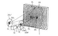
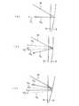
図1、図2に本発明の投影型表示装置と投影スクリーンの概念図を示す。ただし、図1はその投影型表示装置と投影スクリーンの斜視図、図2は図1の水平方向の光路図である。この投影型表示装置は、内部に映像を表示する表示素子と、その表示素子に表示された映像を拡大投影する投影光学系11とを備えた投影装置10と、投影装置10の投影光学系11により投影された投影像近傍に配置された投影スクリーン1とからなる投影型表示装置であって、この図の場合、投影スクリーン1は反射型スクリーンからなる。 1 and 2 are conceptual diagrams of a projection display device and a projection screen according to the present invention. 1 is a perspective view of the projection display device and the projection screen, and FIG. 2 is a horizontal optical path diagram of FIG. The projection display device includes a
投影スクリーン1は、投影光学系11で投影された映像近傍に配置された拡散板3と、投影光学系11の瞳を入射瞳13としてその入射瞳13を1つの観察方向、図の場合は観察者左眼EL近傍の1つの射出瞳20Lに投影する一方のフレネル凹面鏡2Lと、同じ入射瞳13を他の観察方向、図の場合は観察者右眼ER近傍の他の射出瞳20Rに投影する他方のフレネル凹面鏡2Rとからなる。拡散板3は、フレネル凹面鏡2L、2Rと密着するかその近傍に配置される。 The
図2では、フレネル凹面鏡2Lと2Rはそれぞれの中心OL、ORが相互に偏心した凹面鏡として図示してあるが、実際には、同一基板に円錐輪帯状の反射面をそれぞれ中心OL、ORに同心に連結してなる平面状のもので、後で説明するするように、2つのフレネル凹面鏡2Lと2Rは同一面上に同時に重畳して存在し、投影光学系11の瞳を入射瞳13としてその入射瞳13から投影スクリーン1の一点近傍に入射した光束は、2つのフレネル凹面鏡2L、2Rにより同時に異なる方向に反射され、それぞれ射出瞳20L、20Rに別れて入射する。 In FIG. 2, the Fresnel
したがって、射出瞳20Lと20Rに観察者が左眼ELと右眼ERを位置させることにより投影装置10に表示された映像を両眼で同時に観察できる。 Therefore, the image displayed on the
ここで、本発明の投影スクリーン1では、投影装置10による投影像近傍に共通の単一の拡散板3を配置している。そして、その拡散板3に狭い拡散特性を持たせている。これにより、図1に示すように、射出瞳20L、20Rの瞳径が小さい場合であっても、観察しやすい大きさの拡大射出瞳20L’、20R’に拡大することが可能となる。この結果、観察者の眼EL、ERの位置が射出瞳20L、20Rの位置から多少ずれても、拡大射出瞳20L’、20R’から外れない限り、投影像を観察することが可能になる。すなわち、観察しやすい投影型表示装置を提供することが可能となる。また、投影装置10からの投影光はこの2つの拡大射出瞳20L’、20R’に集中して入射するため、照明光を無駄なく投影に利用できるため、照明光源として低電力のものを用いても明るい映像が観察可能な投影型表示装置が得られる。 Here, in the
なお、以上では、フレネル凹面鏡2L、2Rを用いるものとしたが、フレネル凸レンズとその背面に配置した反射鏡を用いてもよい。また、以上では、投影スクリーン1を反射型スクリーンとしたが、透過型スクリーンとして構成してもよい。その場合は、フレネル凹面鏡2L、2Rの代わりに相互に偏心したフレネル凸レンズとして構成すればよい。この場合の拡散板3の作用は反射型スクリーンと同じである。また、フレネル凹面鏡2L、2Rあるいはフレネル凸レンズは相互に偏心した3つ以上のフレネル凹面鏡あるいはフレネル凸レンズとしてもよい。その場合は、1つの入射瞳13の像である射出瞳20L、20Rが3個以上形成され、それに伴って拡大射出瞳20L’、20R’も3個以上形成され、異なる3方向以上から同一の映像を同時に観察することが可能となる。 In the above description, the Fresnel
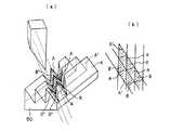
ここで、複数のフレネル凹面鏡又はフレネル凸レンズが相互に偏心して同一基板上に重畳して設けられている場合に、その一点近傍に入射した光束はそれぞれのフレネル凹面鏡又はフレネル凸レンズにより反射作用あるいは屈折作用を同時に受けて異なる複数の方向へ別れて進むことを説明する。図3は、フレネル凹面鏡又はフレネル凸レンズを構成する基板50の表面にバイト51を用いて第1のフレネル凹面鏡又はフレネル凸レンズの作用面Aと非作用面A’とからなる溝(畝)をミクロには略平行に刻んでいく様子を示している。通常、フレネル凹面鏡やフレネル凸レンズの作用面Aは基板50の表面に対して比較的大きく傾斜しており、非作用面A’は基板50の表面に対して略垂直に形成される。図4は、第1のフレネル凹面鏡又はフレネル凸レンズの溝(畝)を刻んだ後に、第2のフレネル凹面鏡又はフレネル凸レンズの作用面Bと非作用面B’とからなる溝(畝)をミクロには略平行に刻んでいく様子を示している。この第1のフレネル凹面鏡又はフレネル凸レンズの溝(畝)と第2のフレネル凹面鏡又はフレネル凸レンズの溝(畝)とは、図4に示すようにほとんどの領域で交差している。第2のフレネル凹面鏡又はフレネル凸レンズの溝(畝)を複数刻むと、図5(a)に示すように、4つの面A、B、A’、B’で囲まれる四角錐の集合が基板50の表面に並列に形成される。その平面図を図5(b)に示す。非作用面A’、非作用面B’は光束の入射側から見ると、線に見えるので、第1のフレネル凹面鏡又はフレネル凸レンズの作用面Aと第2のフレネル凹面鏡又はフレネル凸レンズの作用面Bとが図示のように2次元方向へ交互に密に並んでいるものとなるため、基板の一点(厳密には、ある程度の面積を有する領域)に入射した光束は、面積分割により、作用面Aに入射した成分は第1のフレネル凹面鏡又はフレネル凸レンズの作用を受け、作用面Bに入射した成分は第2のフレネル凹面鏡又はフレネル凸レンズの作用を受けるので、結果的に、第1のフレネル凹面鏡又はフレネル凸レンズによる反射作用あるいは屈折作用と第2のフレネル凹面鏡又はフレネル凸レンズによる反射作用あるいは屈折作用とを同時に受けて異なる2つの方向へ別れて進むことになり、図1、図2で説明したように、投影光学系11の瞳(入射瞳13)から投影スクリーン1の各点近傍に入射した光束は、2つのフレネル凹面鏡2L、2Rにより同時に異なる方向に反射され、それぞれ射出瞳20L、20Rに別れて略同じ光量で入射することになり、略同じ明るさの投影像が同時に観察可能になる。なお、以上の説明は2つのフレネル凹面鏡又はフレネル凸レンズが相互に偏心して同一基板上に重畳して設けられている場合であったが、3つ以上の場合でも同様に説明できる。 Here, in the case where a plurality of Fresnel concave mirrors or Fresnel convex lenses are arranged eccentrically and superimposed on the same substrate, the light beam incident near one point is reflected or refracted by each Fresnel concave mirror or Fresnel convex lens. We will explain that we will be separated and proceed in different directions at the same time. FIG. 3 shows a groove (を) formed by the working surface A and the non-working surface A ′ of the first Fresnel concave mirror or Fresnel convex lens using a
ここで、拡散板3としては、拡散特性に指向性のある微細な凹凸面又は粗面からなるものが用いられる。その場合の拡散板3の拡散角は、半値全幅で20°以下であることが好ましい。拡散板3の拡散角が半値全幅で20°を越えると、拡散角が大きくなりすぎる。この場合、観察視域は広がるが、観察像の明るさが暗くなり、観察物体を照明する照明装置が大掛かりになってしまう。さらに好ましくは、拡散板3の拡散角は、半値全幅で10°以上あるのが好ましい。 Here, as the
さて、以上のような条件を満足する拡散板3としては、特許文献1の作製方法で作製した拡散板が使用可能である。その拡散板としては、以下のものがある。
(1)サンドブラスト法により粒径が制限された球形ビーズを吹き付けて形成されたランダム配置の凹面群あるいはその凹面群に相似的な凹面群、又は、これら凹面群に相補的な凸面群を有する拡散板。
(2)金属基板に球形ビーズを吹き付けて形成されたランダム配置の凹面群を型として透明基板に複製することにより作製された(1)の拡散板。
(3)金属基板上に形成した加工層に球形ビーズを吹き付けて形成されたランダム配置の凹面群を金属基板表面に相似的に転写して形成されたランダム配置の凹面群を型として透明基板に複製することにより作製された(1)の拡散板。
(4)前記球形ビーズの粒径が0.01mmから2mmのガラスビーズからなる(1)から(3)の拡散板。
(5)前記球形ビーズを吹き付ける空気圧が0.5〜3.0kg/cm2である(4)の拡散板。
(6)前記金属基板が真鍮からなる(2)、(4)、(5)の拡散板。
(7)前記金属基板が前記球形ビーズより硬度の高い金属からなる(3)、(4)、(5)の拡散板。
(8)前記金属基板の表面に形成された凹面群を射出成形あるいはプレス成形により透明基板に複製した(2)〜(7)の拡散板。
(9)基板上に樹脂の液滴を噴霧して付着させることにより形成されたランダム配置の凸面群を基板表面に相似的に転写して形成されたランダム配置の凸面群、又は、その凸面群に相補的な凹面群を有する拡散板。As the
(1) Diffusion having a randomly arranged concave surface group formed by spraying spherical beads whose particle size is limited by the sandblast method, a concave surface group similar to the concave surface group, or a convex surface group complementary to the concave surface group Board.
(2) The diffusion plate according to (1), which is produced by replicating a randomly arranged concave surface group formed by spraying spherical beads on a metal substrate onto a transparent substrate.
(3) Randomly arranged concave surface groups formed by spraying spherical beads on a processed layer formed on a metal substrate are transferred to the surface of the metal substrate in a similar manner to form a transparent substrate using the randomly arranged concave surface groups formed as a mold. The diffusion plate of (1) produced by duplicating.
(4) The diffusion plate according to (1) to (3), wherein the spherical beads are made of glass beads having a particle diameter of 0.01 mm to 2 mm.
(5) The diffusion plate according to (4), wherein an air pressure for spraying the spherical beads is 0.5 to 3.0 kg / cm2 .
(6) The diffusion plate according to (2), (4), or (5), wherein the metal substrate is made of brass.
(7) The diffusion plate according to (3), (4), or (5), wherein the metal substrate is made of a metal having higher hardness than the spherical beads.
(8) The diffusion plate according to (2) to (7), wherein the concave surface group formed on the surface of the metal substrate is duplicated on a transparent substrate by injection molding or press molding.
(9) Randomly arranged convex surface group formed by spraying resin droplets on a substrate and adhering them to the substrate surface in a similar manner, or the convex surface group A diffusing plate having a concave group complementary to.
さらに、特許文献2に記載されている拡散板を使うことができる。この拡散板は、透明基体の片面又は両面を粗面化して作製したものである。透明基体の片面又は両面を粗面化する方法としては、例えば以下の(1)〜(4)の方法がある。(1)透明基体の片面又は両面をエッチング処理する方法、(2)樹脂にフィラーを、必要に応じて、水や有機溶剤と共に分散した塗料又はインクをコーティングや印刷を行うことにより、透明基体の片面若しくは両面上に単層又は多層に分けて設ける方法、(3)樹脂やフィラー単体又はこの混合物からなる粉体を静電粉体コーティングや粉体電着コーティングにより、透明基体の片面又は両面に設ける方法、(4)有機又は無機のフィラーを樹脂と共に、熱と圧力を加えることにより溶融し、この溶融物を押し出し成形や射出成形等によりフィルム化して成形する方法。この場合に、この拡散板のHAZE値(JISK7105)が、10〜40の範囲にあることが好ましい。 Furthermore, the diffusion plate described in
また、特許文献3で作製した拡散板を使うこともできる。この拡散板を作製する方法は、基体上に直接又は他の層を介して結着層を積層する工程と、フィラーを加圧媒体によって結着層に埋め込む工程と、その工程で得た積層体に付着した余剰フィラーを除去する工程とを具備している。 Moreover, the diffusion plate produced by
また、拡散板3として、ホログラムからなる拡散板を本発明の投影スクリーン1に用いてもよい。ホログラムからなる拡散板としては、透過型ホログラムと反射型ホログラムとが考えられる。ここで、体積型感光材料中に記録されたホログラムの場合、透過型ホログラムは波長選択性が低く、反射型ホログラムは波長選択性が高い。カラー像を表示する投影型表示装置に用いる場合には、R(赤色)、G(緑色)、B(青色)3波長の光を拡散させるめに3つのホログラム干渉縞を多重記録する必要があるため、ホログラムとしては波長選択性が比較的低い透過型ホログラムを用いる方が望ましい。そして、投影型表示装置を小型に構成するには、フレネル凹面鏡又はフレネル凸レンズとこの透過型ホログラムからなる拡散板と組み合わせて構成することが望ましい。以下、簡単のため、このような透過型ホログラムからなる拡散板3’と1つだけのフレネル凹面鏡2とから投影スクリーンを構成する場合について説明するが、実際には、図1、図2と同様に、相互に偏心配置された左右2つあるいはそれ以上のフレネル凹面鏡2L、2Rの入射側に密着するかその近傍に透過型ホログラムからなる拡散板3’が配置される。 Further, as the
図6(a)に、その場合の投影型表示装置の光学系の概念図を、また、図6(b)に、その投影型表示装置の配置例を示す。なお、図6(a)において、フレネル凹面鏡2は凹面鏡として図示されており、また、投影装置10中の表示素子、照明光源等は図示が省かれている。図6(b)では、表示素子に表示された映像は、投影光学系11で拡大投影される。そして、その投影像近傍には透過型ホログラムからなる拡散板3’とフレネル凹面鏡2とが配置されている。フレネル凹面鏡2は投影光学系11の瞳13の像である射出瞳20を所定の位置に形成する。この所定の位置は、観察者Mの眼球Eと略一致している。投影光学系11のフレネル凹面鏡2により形成された射出瞳20は、拡散板3’によって観察しやすい大きさの拡大射出瞳20’に拡大される。これにより、観察者Mの眼Eの位置が射出瞳20の位置から多少ずれても、投影像を観察像として観察することが可能になる。この結果、図1、図2を用いて説明したように、投影装置10に表示された映像を複数の位置で同時に観察でき、観察しやすい投影型表示装置が得られる。 FIG. 6A shows a conceptual diagram of the optical system of the projection display device in that case, and FIG. 6B shows an arrangement example of the projection display device. In FIG. 6A, the Fresnel
ここで、透過型ホログラムからなる拡散板3’の特徴は、図6(a)に示すように、この拡散板3’はフレネル凹面鏡2の入射側に配置されるため、投影光学系11から拡大射出瞳20’の位置に至る光線は、透過型ホログラム3’を往復で計2回透過する点にある。このような特徴を有するため、光は透過型ホログラム3’で2度回折されることになる。このことを踏まえて、本発明では1回目(フレネル凹面鏡2に入射する前)の透過型ホログラム3’を透過する角度と、2回目(フレネル凹面鏡2に入射した後)の透過型ホログラム3’を透過する角度とを積極的に異ならせて、そのホログラムの角度選択性により何れか一方での回折を避けるようにしている。そのための配置については、後記する。 Here, as shown in FIG. 6A, the
そして、透過型ホログラムからなる拡散板3’は上記の拡散板3と同様に、その拡散角が、同様の理由で半値全幅で20°以下であることが好ましい。さらに好ましくは、拡散板3’の拡散角は、半値全幅で10°以上あるのが好ましい。 The diffusion plate 3 'made of a transmission hologram preferably has a diffusion angle of 20 ° or less in full width at half maximum for the same reason as the
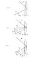
次に、透過型ホログラムからなる拡散板3’の屈曲作用と波長分散の関係、フレネル凹面鏡2と透過型ホログラムからなる拡散板3’の配置関係について説明する。透過型ホログラムからなる拡散板3’は、参照光と拡散光源(2次光源)からの物体光との干渉記録によって作製される。このとき、参照光と物体光が同軸(インライン)配置での記録であると、図7(a)に示したように、投影光学系11からの軸上主光線16は、拡散板3’に1回目の入射をして拡散板3’で屈曲されずに直通する。そして、拡散板3’を直通した主光線は、フレネル凹面鏡2で反射されて方向を変え、拡散板3’を裏面側から入射して拡散板3’を直通する。この際、1回目の入射の際に入射光の入射角度が、透過型ホログラム(拡散板3’)の再生光入射角度(回折効率がピーク近傍になる角度)を満足していれば、1回目の透過の際に直通する主光線の周りに回折による拡散光が分布し、2回目の透過の際にはその拡散光はほとんど直通する。一方、2回目の入射の際に入射光の入射角度が、再生光入射角度を満足していれば、1回目の透過の際には軸上主光線16は回折されずにほとんど直通し、2回目の透過の際に直通する主光線の周りに回折による拡散光が分布する。何れの場合も、0次光170と主光線171は同じ方向に進む。図7(a)はこの様子を示したものであり、拡散光は図示していない。この図では、拡散板3’で回折されない0次光170と回折された拡散光中の主光線(中心光線)171のみを図示してあり、0次光170と主光線171は同じ方向に進み、拡大射出瞳20’の中心に達する。したがって、図7(a)に示すように、透過型ホログラムからなる拡散板3’が拡散作用のみで、光路の屈曲作用を持たない場合は、拡散光だけでなく回折により拡散されない0次光170が拡大射出瞳20’に達する。その結果、観察される映像中心に0次光170のスポットが見えることになり望ましくない。Next, the relationship between the bending action of the diffusing
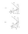
そこで、透過型ホログラムからなる拡散板3’として、参照光と物体光が相互に同軸でないオフライン配置の関係で記録したものを用いる。このようなオフライン配置で記録した拡散板3’は、再生光入射角度を満足して回折する場合に光線の屈曲と共に波長分散が生じる。その屈曲方向によって図7(b)、(c)のような光路と、図8(a)、(b)のような光路とをとる。ただし、図7(b)、(c)は拡散板3’の再生光入射角度条件が1回目の入射の際に満足する場合であり、図8(a)、(b)は2回目の入射の際に満足する場合である。図7(b)、図8(a)は、拡散板3’の屈曲方向が法線に対する入射角に対して回折角が小さくなる方向の場合であり、図7(c)、図8(b)は、入射角に対して回折角が大きくなる方向の場合である。各図中、拡散光の図示は省き、拡散板3’で回折して屈曲されたR、G、Bの波長の主光線(中心光線)をそれぞれ17R、17G、17Bで示してある。各図から明らかなように、拡散板3’のとして光線の屈曲作用を持つ透過型ホログラムを用いると、ホログラムで回折されない0次光170を回折光17R、17G、17Bから分離できる。その結果、拡大射出瞳20’に入射しないように構成可能になる。具体的には、拡大射出瞳20’の位置で、拡大射出瞳20’の中心からその瞳径の2分の1以上離れて0次光170が入射するように構成することが望ましい。Therefore, a diffusing
なお、透過型ホログラムでの屈曲角(偏角)を上記入射角と回折角の差の絶対値γで定義し、かつ、その屈曲角をd線(波長587.6nm)で測るとした場合、屈曲角γが小さすぎると、上記のように観察像中に0次光が入射する。逆に、大きすぎると、波長分散が大きくなりすぎて拡大射出瞳20’でR、G、Bの3波長が重なる範囲、すなわち色再現性良く観察できる射出瞳範囲が小さくなりすぎてしまう。 When the bending angle (deflection angle) in the transmission hologram is defined by the absolute value γ of the difference between the incident angle and the diffraction angle, and the bending angle is measured by the d-line (wavelength 587.6 nm), If the bending angle γ is too small, zero-order light enters the observation image as described above. On the other hand, if it is too large, the chromatic dispersion becomes too large, and the range in which the three wavelengths R, G, and B overlap on the enlarged exit pupil 20 ', that is, the exit pupil range that can be observed with good color reproducibility becomes too small.
したがって、透過型ホログラムからなる拡散板3’のd線での屈曲角(偏角)γは、
γ>1° ・・・(1)
の関係を満たす必要がある。Therefore, the bending angle (deflection angle) γ at the d-line of the diffusing
γ> 1 ° (1)
It is necessary to satisfy the relationship.
さらに好ましくは、
γ>2° ・・・(1−1)
なる条件を満足することが好ましい。More preferably,
γ> 2 ° (1-1)
It is preferable to satisfy the following conditions.
さらに好ましくは、
γ>10° ・・・(1−2)
なる条件を満足することが望ましい。More preferably,
γ> 10 ° (1-2)
It is desirable to satisfy the following conditions.
また、
γ<45° ・・・(2)
の関係を満たす必要がある。Also,
γ <45 ° (2)
It is necessary to satisfy the relationship.
さらに好ましくは、
γ<20° ・・・(2−1)
なる条件を満足することが好ましい。More preferably,
γ <20 ° (2-1)
It is preferable to satisfy the following conditions.
上記の条件(1−2)と(2−1)を組み合わせると、次の条件(3)となる。 When the above conditions (1-2) and (2-1) are combined, the following condition (3) is obtained.
10°<γ<20° ・・・(3)
この条件(3)についてさらに説明する。この条件の下限の10°を下回ると、0次光と表示像を観察可能にする正規観察光との分離が少なくなる。そのため、観察者が僅かに頭を動かすと、0次光が眼に入ってまぶしくなることが多くなる。また、この条件の上限の20°を越えると、透過型ホログラム3’による色分散が大きくなり、その結果観察範囲が狭くなってしまう。10 ° <γ <20 ° (3)
This condition (3) will be further described. If the lower limit of 10 ° is not satisfied, the separation between the zero-order light and the normal observation light that enables the display image to be observed decreases. Therefore, when the observer moves his head slightly, the 0th-order light often enters the eye and becomes dazzling. If the upper limit of 20 ° is exceeded, chromatic dispersion by the
さらに、Rを700nmの波長の光、Bを400nmの波長の光としたとき、回折光17Rと17Bの間の回折角の差は、小さい程望ましい。具体的には、18°以下であることが、上記のように色再現性良く観察できる射出瞳範囲が小さくなりすぎないために必要である。また、拡大射出瞳20’の位置では、Rを700nmの波長の光、Bを400nmの波長の光としたとき、回折光17Rと17Bの間の入射位置の差も小さい程望ましい。具体的には、拡大射出瞳20’の瞳径の2分の1以下であるように構成することが望ましい。Further, when R is light having a wavelength of 700 nm and B is light having a wavelength of 400 nm, the difference in diffraction angle between the diffracted
ところで、図7、図8においては、投影光学系11からの軸上主光線16あるいは0次光170はフレネル凹面鏡2に斜め(フレネル凹面鏡2の入射位置での鏡面の法線に対して角度βをなす。)に入射することを考えていた。ここで、軸上主光線16あるいは0次光170がフレネル凹面鏡2の鏡面に略直角(β≒0°)に入射すると、拡散板3’を2度通過した後にホログラムから射出する主光線17R、17G、17Bは軸上主光線16と略反対方向に向かう。そのため、拡大射出瞳20’の位置と投影光学系11が干渉することになる。そこで、フレネル凹面鏡2に入射する投影光学系11からの軸上主光線16又はその0次光170のフレネル凹面鏡2の鏡面への入射角βは、
0°<β<45° ・・・(4)
の関係を満たすことが望ましい。Incidentally, FIG. 7, 8, the angle to the normal of the mirror surface at the incident position of the diagonal (Fresnel
0 ° <β <45 ° (4)
It is desirable to satisfy the relationship.
さらに好ましくは、
5°<β<20° ・・・(4−1)
なる条件を満足することが好ましい。More preferably,
5 ° <β <20 ° (4-1)
It is preferable to satisfy the following conditions.
この条件(4−1)についてさらに説明する。この条件の下限の5°を上回ると、フレネル凹面鏡2の偏心量が小さくなる。そのため、拡散板3’で共役再生が起こり、表示像観察に利用可能な光量が低下する。また、この条件の上限の20°を越えると、フレネル凹面鏡2の偏心量が大きくなりすぎる。そのため、投影される瞳収差が大きくなり、均一な明るさの像を観察することが困難になってしまう。 This condition (4-1) will be further described. When the lower limit of 5 ° is exceeded, the amount of eccentricity of the Fresnel
また、図7、図8においては、投影光学系11からの軸上主光線16が透過型ホログラムからなる拡散板3’及びその裏面側のフレネル凹面鏡2に入射する位置は、それぞれの略中心で、拡散板3’とフレネル凹面鏡2の間には偏心はないものとした。その場合、図7、図8から明らかなように、拡散板3’を2度通過した投影光(回折光)17R、17G、17Bは拡散板3’に対して角度をなしており、拡大射出瞳20’は拡散板3’の正面には位置せず斜め方向から投影された映像を見ることになり、観察される像はアオリ像となって像歪みが発生する。そこで、図9(a)〜(c)に示すように、フレネル凹面鏡2を拡散板3’に対して偏心させて(何れの図も上方へ偏心させている。)、フレネル凹面鏡2で反射された主光線17R、17G、17Bが拡散板3’を2度目に通過して拡散板3’に対して略直角をなすようにしている。なお、図9(a)〜(c)はそれぞれ図7(a)〜(c)に対応する場合である。7 and 8, the axial
なお、投影光学系11からの拡散板3’上に斜め方向から投影像を入射させるので、拡散板3’上での投影像もアオリ像となって像歪みが発生する。そのため、投影光学系11はこのようなアオリ像の像歪みを補正する機能を持ったものと使用するのが望ましい。 Since the projection image is incident on the
また、拡大射出瞳20’を拡散板3’の正面(実際には、拡大射出瞳20’は図1、図2に示すように複数形成するようにするので、側面図で見て正面)に位置するようにし、かつ、投影光学系11からの軸上主光線16あるいは0次光170はフレネル凹面鏡2に斜めに入射するようにすることにより、拡散板3’に入射する投影光学系11からの投影光がその表面で反射してノイズ光になる表面正反射光を拡大射出瞳20’に入射させないようにする効果も得られる。Further, the
なお、上記の屈曲角(偏角)γとフレネル凹面鏡2の鏡面への入射角βの比γ/βは、
0.01<γ/β<1000 ・・・(5)
の関係を満たすことが望ましい。Note that the ratio γ / β of the bending angle (deflection angle) γ and the incident angle β to the mirror surface of the Fresnel
0.01 <γ / β <1000 (5)
It is desirable to satisfy the relationship.
さらに好ましくは、
0.5<γ/β<2 ・・・(5−1)
なる条件を満足することが好ましい。More preferably,
0.5 <γ / β <2 (5-1)
It is preferable to satisfy the following conditions.
この条件(5−1)についてさらに説明する。この条件の下限の0.5を下回ると、透過型ホログラム3’の屈曲角が小さくなる。そのため、透過型ホログラム3’で回折しない0次光が拡大射出瞳20’に入射してしまい、観察像にスポットフレアーがのることになる。また、上限の2を越えると、フレネル凹面鏡2の偏心量が比較的小さくなる。この場合、透過型ホログラム3’に入射した後、フレネル凹面鏡2で反射してから、透過型ホログラム3’の裏面で極僅かではあるがフレネル反射により反射され、再度フレネル凹面鏡2で反射する光線が存在する。そして、その光線が拡大射出瞳20’に入射してしまう。この光線もスポットフレアーとして観察されてしまうので、好ましくない。 This condition (5-1) will be further described. Below the lower limit of 0.5 of this condition, the bending angle of the transmission hologram 3 'becomes small. Therefore, the 0th-order light that is not diffracted by the
さらに好ましくは、
1<γ/β<1.5 ・・・(5−2)
なる条件を満足することが、スポットフレアーの点でより好ましい。More preferably,
1 <γ / β <1.5 (5-2)
It is more preferable in terms of spot flare to satisfy the following conditions.
ところで、透過型ホログラムからなる拡散板3’を用いる場合は、投影装置10中の表示素子を照明する光源は、単色性の高いLEDやLDをRGB3色組み合わせてなる光源を用いることが望ましい。 By the way, when the diffusing
次に、投影光学系11の瞳13を拡大投影するフレネル凹面鏡2L、2Rと透過型ホログラムからなる拡散板3’の組み合わせからなる投影スクリーン1の実施例1について説明する。この実施例において、光線追跡は、投影光学系11の瞳13を物体面とし、拡大射出瞳20L’、20R’を像面とし、投影光学系11の瞳13の中心から拡大射出瞳20L’、20R’までの順光線追跡で行っている。 Next, a first embodiment of the
実施例1のX−Z面への投影光路図を図10に、Y−Z面への投影光路図を図11に示す。また、図12にこの実施例の拡散板3’に用いる透過型ホログラムの撮影配置を示す。そして、図13にこの実施例における拡大射出瞳20L’(20R’)位置での波長450nm、波長550nm、波長650nmでの射出瞳像の重なり具合と、0次光及び表面反射光の入射位置を示す。なお、図12、図13中の数字はmm単位である。 FIG. 10 shows a projection optical path diagram on the XZ plane of Example 1, and FIG. 11 shows a projection optical path diagram on the YZ plane. Further, FIG. 12 shows a photographing arrangement of a transmission hologram used for the diffusion plate 3 'of this embodiment. FIG. 13 shows the overlapping state of the exit pupil images at the positions of the
実施例1は、図7(c)(図9(c))に対応して再生光入射角度条件が1回目の入射の際に満足し、2回目には回折せず、かつ、拡散板3’の屈曲方向が法線に対する入射角に対して回折角が大きくなる方向の場合の例ある。また、フレネル凹面鏡2L、2Rはフレネル裏面鏡で構成されており、そのフレネル裏面鏡のX方向、Y方向への偏心量をMX、MY、軸上主光線30(30L、30R)の透過型ホログラム3’による偏角量をγ、フレネル凹面鏡2L、2Rの鏡面への入射角をβとするとすると、
MX=20mm(フレネル凹面鏡2L)、−20mm(フレネル凹面鏡2R)
MY=157.23mm
γ=15.00°(屈折率1.4924の硝材中で)
β=12.57°(屈折率1.4924の硝材中で)
である。Example 1 corresponds to FIG. 7C (FIG. 9C), and the reproduction light incident angle condition is satisfied when the light is incident for the first time, and is not diffracted for the second time. In this example, the bending direction of 'is a direction in which the diffraction angle is larger than the incident angle with respect to the normal. Further, the Fresnel
MX = 20 mm (Fresnel
MY = 157.23mm
γ = 15.00 ° (in glass material with a refractive index of 1.4924)
β = 12.57 ° (in a glass material having a refractive index of 1.4924)
It is.
また、この実施例の透過型ホログラム3’の露光条件は、図12(a)中に示す通り、露光の際の座標系を透過型ホログラム3’の面の軸上主光線30(30L、30R)の入射点を原点にして、ホログラム面をX−Y面とし、投影光学系11の瞳13から離れる方向をZ軸とするとき、ホログラムの寸法を、図12(b)に示すように、縦×横を190mm×250mmのものを用い、露光のための第1光源位置(X1,Y1,Z1)は以下の通りであり、点光源とする。 Further, as shown in FIG. 12A, the exposure conditions of the
(X1,Y1,Z1)=(0,297.11,−578.12)
また、第2光源中心位置(X2,Y2,Z2)は以下の通りであり、図12(c)に示すように、縦×横が144.44mm×86.67mmの面積を持つ拡散面光源とする。(X1, Y1, Z1) = (0, 297.11, −578.12)
The second light source center position (X2, Y2, Z2) is as follows. As shown in FIG. 12 (c), the diffusion surface light source having an area of 144.44 mm × 86.67 mm in length × width is To do.
(X2,Y2,Z2)=(0,435.32,−482.72)
以上の露光条件で作製した透過型ホログラムを拡散板3’として使用することにより、拡散板3’により拡散された光束は、フレネル凹面鏡2L、2R反射された後、図13に一方の拡大射出瞳を示すように、観察者瞳面で色再現性良く観察できる射出瞳範囲が縦×横が60mm×60mmの正方形で、X方向への偏心量が以下のPXの拡大射出瞳20L’、20R’となり、それらの中にφ60の円形瞳が可能になる。この実施例の瞳の色収差(波長450nmの射出瞳像と波長650nmの射出瞳像とのズレ)は40mmとなる。(X2, Y2, Z2) = (0, 435.32, -482.72)
By using the transmission hologram produced under the above exposure conditions as the
PX=34.87mm(拡大射出瞳20L’)、
−34.87mm(拡大射出瞳20R’)
以下に、上記実施例1の構成パラメータを示す。上記のように、実施例1においては、軸上主光線30L、30Rを、投影光学系11の瞳13の中心を出て透過型ホログラムからなる拡散板3’の中心を通り拡大射出瞳20L’、20R’中心に至る光線で定義する。PX = 34.87 mm (
-34.87mm (
The configuration parameters of Example 1 are shown below. As described above, in the first embodiment, the axial
そして、実施例1においては、順光線追跡において、投影光学系11の瞳13の中心を原点とし、瞳面をX−Y面とし、フレネル凹面鏡2L、2Rの中心OL、ORを結ぶ方向をX軸方向とし、ORからOLに至る方向をX軸正方向とし、瞳に垂直な軸上主光線30L、30Rの進行方向をZ軸正方向としている。 In the first embodiment, in forward ray tracing, the center of the
そして、偏心面については、光学系の原点からその面の面頂位置の偏心量(X軸方向、Y軸方向、Z軸方向をそれぞれX,Y,Z)と、その面の中心軸(非球面については、下記(a)式のZ軸)のX軸、Y軸、Z軸それぞれを中心とする傾き角(それぞれα,β,γ(°))とが与えられている。その場合、αとβの正はそれぞれの軸の正方向に対して反時計回りを、γの正はZ軸の正方向に対して時計回りを意味する。なお、面の中心軸のα,β,γの回転のさせ方は、面の中心軸とそのXYZ直交座標系を、まずX軸の回りで反時計回りにα回転させ、次に、その回転した面の中心軸を新たな座標系のY軸の回りで反時計回りにβ回転させると共に1度回転した座標系もY軸の回りで反時計回りにβ回転させ、次いで、その2度回転した面の中心軸を新たな座標系の新たな座標系のZ軸の回りで時計回りにγ回転させるものである。 For the decentered surface, the amount of decentration from the origin of the optical system to the surface top position of the surface (X, Y, and Z directions are X, Y, Z, respectively) and the center axis of the surface (non- With respect to the spherical surface, inclination angles (α, β, γ (°), respectively) about the X axis, the Y axis, and the Z axis of the following equation (a) are given. In this case, positive α and β mean counterclockwise rotation with respect to the positive direction of each axis, and positive γ means clockwise rotation with respect to the positive direction of the Z axis. Note that the α, β, and γ rotations of the central axis of the surface are performed by first rotating the central axis of the surface and its XYZ orthogonal coordinate system by α counterclockwise around the X axis, and then rotating the rotation. The center axis of the surface is rotated β counterclockwise around the Y axis of the new coordinate system, and the coordinate system rotated once is also rotated β counterclockwise around the Y axis and then rotated twice. The center axis of the surface is rotated γ clockwise around the Z axis of the new coordinate system.
また、本発明で用いられる非球面は、以下の定義式で与えられる回転対称非球面である。 The aspherical surface used in the present invention is a rotationally symmetric aspherical surface given by the following definition.
Z=(Y2/R)/[1+{1−(1+K)Y2/R2}1 /2]
+AY4+BY6+CY8+DY10+…… ・・・(a)
ただし、Zを光の進行方向を正とした光軸(軸上主光線)とし、Yを光軸と垂直な方向にとる。ここで、Rは近軸曲率半径、Kは円錐定数、A、B、C、D、…はそれぞれ4次、6次、8次、10次の非球面係数である。この定義式のZ軸が回転対称非球面の軸となる。Z = (Y 2 / R) / [1+ {1- (1 + K)
+ AY4 + BY6 + CY8 + DY10 +... (A)
However, Z is an optical axis (axial principal ray) with the light traveling direction being positive, and Y is a direction perpendicular to the optical axis. Here, R is a paraxial radius of curvature, K is a conic constant, A, B, C, D,... Are fourth-order, sixth-order, eighth-order, and tenth-order aspherical coefficients, respectively. The Z axis of this defining formula is the axis of a rotationally symmetric aspherical surface.
なお、データの記載されていない非球面に関する項は0である。屈折率については、d線(波長587.56nm)に対するものを表記してある。長さの単位はmmである。 The term relating to the aspherical surface for which no data is described is zero. The refractive index is shown for d-line (wavelength 587.56 nm). The unit of length is mm.
以下に、上記実施例1の構成パラメータを示す。なお、以下の表中の“ASS”は非球面、“FL”はフレネル面、“RE”は反射面、“HOE”は透過型ホログラム、“PIM”は画像投影面をそれぞれ示す。 The configuration parameters of Example 1 are shown below. In the table below, “ASS” represents an aspheric surface, “FL” represents a Fresnel surface, “RE” represents a reflecting surface, “HOE” represents a transmission hologram, and “PIM” represents an image projection surface.
実施例1
面番号 曲率半径 面間隔 偏心 屈折率 アッベ数
物体面 ∞
1 HOE 偏心(1) 1.4924 57.6
2 ∞(PIM) 偏心(1) 1.4924 57.6
3 ASS(1) (RE,FL) 偏心(2) 1.4924 57.6
4 ∞ 偏心(1)
像 面 ∞ 偏心(3)
ASS(1)
R -407.45
K -5.8103×10
A -7.5130×10⁻⁷
B 7.5802×10⁻¹²
C -3.1478×10⁻¹⁷
偏心(1)
X 0.00 Y 0.00 Z 650.00
α 25.00 β 0.00 γ 0.00
偏心(2)
X MX Y MY Z 577.79
α 25.00 β 0.00 γ 0.00
偏心(3)
X PX Y -190.18 Z 242.16
α 25.00 β 0.00 γ 0.00 。
Example 1
Surface number Curvature radius Surface spacing Eccentricity Refractive index Abbe number Object surface ∞
1 HOE Eccentricity (1) 1.4924 57.6
2 ∞ (PIM) Eccentricity (1) 1.4924 57.6
3 ASS (1) (RE, FL) Eccentricity (2) 1.4924 57.6
4 ∞ Eccentricity (1)
Image plane ∞ Eccentricity (3)
ASS (1)
R -407.45
K -5.8103 × 10
A -7.5130 × 10⁻⁷
B 7.5802 × 10⁻¹²
C -3.1478 × 10⁻¹⁷
Eccentricity (1)
X 0.00 Y 0.00 Z 650.00
α 25.00 β 0.00 γ 0.00
Eccentric (2)
X MX Y MY Z 577.79
α 25.00 β 0.00 γ 0.00
Eccentricity (3)
X PX Y -190.18 Z 242.16
α 25.00 β 0.00 γ 0.00.
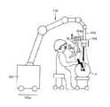
さて、このような本発明の投影スクリーンと投影型表示装置は、図14に示すように、例えば手術用立体観察システムに用いることができる。図14は、この手術用立体観察システムの1実施例を示す説明図であり、本実施例の製品は、キャスター105a付き支持部本体105に、自在アーム110が接続されている。そして、自在アーム110を介して、支持アーム104が取り付けられている。この支持アーム104は、3次元方向に移動自在で、360°回転自在になっている。また、その支持アーム104には、連結部104dを介して保持部材103が取り付けられている。この保持部材103も、移動自在、回転自在になっている。そして、保持部材103には、投影装置10と本発明のスクリーン1とが取り付けられている。 Now, such a projection screen and projection display device of the present invention can be used in, for example, a surgical stereoscopic observation system as shown in FIG. FIG. 14 is an explanatory view showing one embodiment of this surgical stereoscopic observation system. In the product of this embodiment, a
一方、支持アーム104先端には、手術用顕微鏡の画像入力部109が取り付けられている。画像入力部109にはカメラが内蔵され、患者Pの患部を撮影する。撮影された画像は、入力画像として投影型表示装置に送られる。より詳しくは、投影装置10に送られるように構成されている。 On the other hand, an
このように構成することで、図14の装置では、手術用顕微鏡で患者Pの患部の映像を両眼EL、ERで観察しながら手術を行うことができるようになっている。 With this configuration, the apparatus shown in FIG. 14 can perform surgery while observing an image of the affected area of the patient P with the binocular EL and ER with a surgical microscope.
また、本発明の投影スクリーンと投影型表示装置は、パソコン、電話、特に持ち運びに便利な携帯電話等の情報処理装置に用いることができる。そのような投影型表示装置としての例を図15に示す。図15は携帯電話の例である。 Further, the projection screen and the projection display device of the present invention can be used for information processing devices such as a personal computer, a telephone, and especially a mobile phone that is convenient to carry. An example of such a projection display device is shown in FIG. FIG. 15 shows an example of a mobile phone.
この携帯電話138には、マイク部139と、スピーカ部140と、アンテナ141と、142と、本発明の投影観察装置とが設けられている。ここで、マイク部139は、操作者の声を情報として入力する。スピーカ部140は、通話相手の声を出力する。アンテナ141は、通信電波の送信と受信を行う。操作ボタン142は、操作者が情報を入力するのに使われる。 The
本発明の投影スクリーンと投影型表示装置は、操作者自身や通話相手等の撮影像と、電話番号等の情報を投影表示するために用いられる。ここでは、投影装置10と本発明のスクリーン1を設けて、その拡大射出瞳20L’、20R’の位置でその表示映像を無理なく両眼で観察できるようにしている。 The projection screen and the projection display device of the present invention are used for projecting and displaying a photographed image of the operator and the other party and information such as a telephone number. Here, the
また、本発明の投影スクリーンと投影型表示装置は、以上のような携帯型の使用形態に限らず、図17に示すような手持ちビュワータイプの形態にも適用可能であり、この構成の場合、投影型表示装置の本体60に折り畳み可能に設けた投影装置10の支持部材61を、本体60に設けた本発明の投影スクリーン1の保護カバーの役目を兼用するようにすることにより、携帯時の防塵性を向上させることが可能となる。 In addition, the projection screen and the projection display device of the present invention are not limited to the above-described portable use form, but can also be applied to a handheld viewer type form as shown in FIG. By supporting the
以上、本発明の投影スクリーン及び投影型表示装置を実施例に基づいて説明してきたが、本発明はこれら実施例に限定されず種々の変形が可能である。 As described above, the projection screen and the projection display device of the present invention have been described based on the embodiments. However, the present invention is not limited to these embodiments, and various modifications can be made.
本発明の投影スクリーン及び投影型表示装置は例えば次のように構成することができる。 The projection screen and the projection display device of the present invention can be configured as follows, for example.
〔1〕 複数のフレネル凹面鏡が相互に偏心して同一基板上に重畳して設けられてなることを特徴とする投影スクリーン。 [1] A projection screen in which a plurality of Fresnel concave mirrors are eccentrically arranged and overlapped on the same substrate.
〔2〕 複数のフレネル凸レンズが相互に偏心して同一基板上に重畳して設けられその背面に反射鏡が配置されてなることを特徴とする投影スクリーン。 [2] A projection screen characterized in that a plurality of Fresnel convex lenses are decentered from each other and are superimposed on the same substrate, and a reflecting mirror is disposed on the back surface thereof.
〔3〕 複数のフレネル凸レンズが相互に偏心して同一基板上に重畳して設けられてなることを特徴とする投影スクリーン。 [3] A projection screen in which a plurality of Fresnel convex lenses are decentered from each other and superimposed on the same substrate.
〔4〕 前記複数のフレネル凹面鏡又はフレネル凸レンズは基板に設けられた角錐状の突起群又は穿孔群からなり、前記突起群又は穿孔群を構成する突起又は穿孔の少なくとも一部は、少なくとも2つの光学作用面と少なくとも2つの光学非作用面とからなる角錐状の突起又は穿孔からなることを特徴とする上記1から3の何れか1項記載の投影スクリーン。 [4] The plurality of Fresnel concave mirrors or Fresnel convex lenses are composed of pyramidal projections or perforations provided on a substrate, and at least some of the projections or perforations constituting the projections or perforations are at least two optical elements. 4. The projection screen according to any one of
〔5〕 前記投影スクリーンの投影光入射側あるいは反射側に拡散板が配置されていることを特徴とする上記1から4の何れか1項記載の投影スクリーン。 [5] The projection screen as described in any one of [1] to [4] above, wherein a diffusion plate is disposed on the projection light incident side or the reflection side of the projection screen.
〔6〕 前記拡散板が透過型ホログラムからなる拡散板であることを特徴とする上記5記載の投影スクリーン。 [6] The projection screen as described in 5 above, wherein the diffusion plate is a diffusion plate made of a transmission hologram.
〔7〕 前記拡散板が拡散特性に指向性のある微細な凹凸面又は粗面からなる拡散板であることを特徴とする上記5記載の投影スクリーン。 [7] The projection screen as described in [5] above, wherein the diffusing plate is a diffusing plate having a fine uneven surface or a rough surface having directivity in diffusion characteristics.
〔8〕 前記拡散板の拡散角は、半値全幅で20°以下であることを特徴とする上記5から7の何れか1項記載の投影スクリーン。 [8] The projection screen according to any one of 5 to 7, wherein a diffusion angle of the diffusion plate is 20 ° or less in full width at half maximum.
〔9〕 前記透過型ホログラムの1回目及び2回目透過時に回折されてない0次光が前記複数のフレネル凹面鏡又は複数のフレネル凸レンズで結像され前記透過型ホログラムで拡大された拡大射出瞳に入射しないように構成されていることを特徴とする上記6記載の投影スクリーン。 [9] Zero-order light that has not been diffracted during the first and second transmissions of the transmission hologram is imaged by the plurality of Fresnel concave mirrors or a plurality of Fresnel convex lenses and is incident on the enlarged exit pupil enlarged by the transmission hologram 7. The projection screen as described in 6 above, wherein the projection screen is configured not to be used.
〔10〕 前記拡大射出瞳の位置で、前記透過型ホログラムの1回目及び2回目透過時に回折されてない0次光がその拡大射出瞳の中心からその瞳径の2分の1以上離れて入射するように構成されていることを特徴とする上記9記載の投影スクリーン。 [10] Zero-order light that is not diffracted during the first and second transmissions of the transmission hologram is incident at a position of the magnified exit pupil at a distance of more than one half of the pupil diameter from the center of the magnified exit pupil. 10. The projection screen as described in 9 above, wherein the projection screen is configured as described above.
〔11〕 前記透過型ホログラムからなる拡散板が、回折による屈曲作用を有することを特徴とする上記6、9、10の何れか1項記載の投影スクリーン。 [11] The projection screen as set forth in any one of 6, 9, and 10, wherein the diffusion plate made of the transmission hologram has a bending action by diffraction.
〔12〕 前記透過型ホログラムからなる拡散板によるd線の光軸の屈曲角をγとするとき、
γ>1° ・・・(1)
の条件を満足することを特徴とする上記11記載の投影スクリーン。[12] When the bending angle of the optical axis of the d line by the diffusion plate made of the transmission hologram is γ,
γ> 1 ° (1)
12. The projection screen as described in 11 above, wherein the following condition is satisfied.
〔13〕 前記透過型ホログラムからなる拡散板によるd線の光軸の屈曲角をγとするとき、
γ<45° ・・・(2)
の条件を満足することを特徴とする上記11記載の投影スクリーン。[13] When the bending angle of the optical axis of the d line by the diffusion plate made of the transmission hologram is γ,
γ <45 ° (2)
12. The projection screen as described in 11 above, wherein the following condition is satisfied.
〔14〕 前記透過型ホログラムからなる拡散板によるd線の光軸の屈曲角をγとするとき、
10°<γ<20° ・・・(3)
なる条件を満足することを特徴とする上記11記載の投影スクリーン。[14] When the bending angle of the optical axis of the d-line by the diffusion plate made of the transmission hologram is γ,
10 ° <γ <20 ° (3)
12. The projection screen as described in 11 above, wherein the following condition is satisfied.
〔15〕 前記透過型ホログラムからなる拡散板による波長700nmの光と波長400nmの光の間の光軸の回折角の差が18°以下であることを特徴とする上記6、9〜14の何れか1項記載の投影スクリーン。 [15] Any of the above 6, 9 to 14, wherein the difference in the diffraction angle of the optical axis between the light with a wavelength of 700 nm and the light with a wavelength of 400 nm by the diffusion plate made of the transmission hologram is 18 ° or less A projection screen according to
〔16〕 前記拡大射出瞳の位置で、波長700nmの光軸と波長400nmの光軸の入射位置の差が射出瞳の瞳径の2分の1以下であることを特徴とする上記9〜15の何れか1項記載の投影スクリーン。 [16] The above items 9 to 15, wherein the difference between the incident positions of the optical axis having a wavelength of 700 nm and the optical axis having a wavelength of 400 nm is less than or equal to one half of the pupil diameter of the exit pupil at the position of the enlarged exit pupil. The projection screen according to any one of the above.
〔17〕 前記フレネル凹面鏡の鏡面へのd線の光軸の入射角をβとするとき、
0°<β<45° ・・・(4)
の関係を満たすことを特徴とする上記6、9、10の何れか1項記載の投影スクリーン。[17] When the incident angle of the optical axis of the d-line to the mirror surface of the Fresnel concave mirror is β,
0 ° <β <45 ° (4)
The projection screen according to any one of the
〔18〕 前記フレネル凹面鏡の鏡面へのd線の光軸の入射角をβとするとき、
5°<β<20° ・・・(4−1)
の関係を満たすことを特徴とする上記6、9、10の何れか1項記載の投影スクリーン。[18] When the incident angle of the optical axis of the d-line to the mirror surface of the Fresnel concave mirror is β,
5 ° <β <20 ° (4-1)
The projection screen according to any one of the
〔19〕 前記透過型ホログラムからなる拡散板によるd線の光軸の屈曲角をγ、前記フレネル凹面鏡の鏡面へのd線の光軸の入射角をβとするとき、
0.01<γ/β<1000 ・・・(5)
の関係を満たすことを特徴とする上記6、9〜18の何れか1項記載の投影スクリーン。[19] When the bending angle of the optical axis of the d-line by the diffusion plate made of the transmission hologram is γ, and the incident angle of the optical axis of the d-line to the mirror surface of the Fresnel concave mirror is β,
0.01 <γ / β <1000 (5)
The projection screen according to any one of the above items 6 and 9 to 18, wherein the relationship is satisfied.
〔20〕 前記透過型ホログラムからなる拡散板によるd線の光軸の屈曲角をγ、前記フレネル凹面鏡の鏡面へのd線の光軸の入射角をβとするとき、
0.5<γ/β<2 ・・・(5−1)
の関係を満たすことを特徴とする上記6、9〜18の何れか1項記載の投影スクリーン。[20] When the bending angle of the optical axis of the d line by the diffusion plate made of the transmission hologram is γ, and the incident angle of the optical axis of the d line to the mirror surface of the Fresnel concave mirror is β,
0.5 <γ / β <2 (5-1)
The projection screen according to any one of the above items 6 and 9 to 18, wherein the relationship is satisfied.
〔21〕 映像を表示する表示素子と、前記表示素子に表示された映像を拡大投影する投影光学系と、前記投影光学系により投影された投影像近傍に配置された投影スクリーンとからなる投影型表示装置において、
前記投影スクリーンが上記1から20の何れか1項記載の投影スクリーンからなることを特徴とする投影型表示装置。[21] A projection type comprising a display element for displaying an image, a projection optical system for enlarging and projecting the image displayed on the display element, and a projection screen arranged in the vicinity of the projection image projected by the projection optical system In the display device,
21. A projection type display apparatus, wherein the projection screen comprises the projection screen according to any one of 1 to 20 above.
〔22〕 前記投影光学系はアオリ像の像歪みを補正する機能を持ったものであることを特徴とする上記21記載の投影型表示装置。 [22] The projection display device as described in 21 above, wherein the projection optical system has a function of correcting image distortion of the tilted image.
〔23〕 照明光源としてLED又はLDを用いたことを特徴とする上記21又は22記載の投影型表示装置。 [23] The projection display device as described in 21 or 22 above, wherein an LED or LD is used as the illumination light source.
M…観察者
P…患者
EL、ER…観察者眼球
OL、OR…フレネル凹面鏡の中心
A、B…作用面
A’、B’…非作用面
1…投影スクリーン
2、2L、2R…フレネル凹面鏡
3…拡散板
3’…透過型ホログラムからなる拡散板
10…投影装置
11…投影光学系
13…入射瞳
16…投影光学系からの軸上主光線
170…0次光
171…拡散光中の主光線(中心光線)
17R、17G、17B…透過型ホログラムからなる拡散板で回折して屈曲されたR、G、Bの波長の主光線(中心光線)
20、20L、20R…射出瞳
20’、20L’、20R’…拡大射出瞳
30、30L、30R…軸上主光線
50…フレネル凹面鏡、フレネル凸レンズを構成する基板
51…バイト
60…投影型表示装置の本体
61…支持部材
103…保持部材
104…支持アーム
104d…連結部
105…支持部本体
105a…キャスター
109…画像入力部
110…自在アーム
138…携帯電話
139…マイク部
140…スピーカ部
141…アンテナ
142…操作ボタンM ... observer P ... patient EL, ER ... observer eyeball OL, OR ... center of Fresnel concave mirror A, B ... working surface A ', B' ...
17R , 17G , 17B ... Chief rays (central rays) having wavelengths of R, G, and B diffracted and bent by a diffusion plate made of a transmission hologram
20, 20L, 20R ... exit
Claims (4)
Translated fromJapanese前記投影スクリーンが請求項1から3の何れか1項記載の投影スクリーンからなることを特徴とする投影型表示装置。In a projection display device comprising a display element for displaying an image, a projection optical system for enlarging and projecting the image displayed on the display element, and a projection screen arranged in the vicinity of a projection image projected by the projection optical system ,
A projection type display apparatus comprising the projection screen according to any one of claims 1 to 3.
Priority Applications (2)
| Application Number | Priority Date | Filing Date | Title |
|---|---|---|---|
| JP2003289904AJP2005062312A (en) | 2003-08-08 | 2003-08-08 | Projection screen and projection type display device |
| US10/913,488US7167307B2 (en) | 2003-08-08 | 2004-08-09 | Projection screen, and projection type display system |
Applications Claiming Priority (1)
| Application Number | Priority Date | Filing Date | Title |
|---|---|---|---|
| JP2003289904AJP2005062312A (en) | 2003-08-08 | 2003-08-08 | Projection screen and projection type display device |
Publications (1)
| Publication Number | Publication Date |
|---|---|
| JP2005062312Atrue JP2005062312A (en) | 2005-03-10 |
Family
ID=34114104
Family Applications (1)
| Application Number | Title | Priority Date | Filing Date |
|---|---|---|---|
| JP2003289904AWithdrawnJP2005062312A (en) | 2003-08-08 | 2003-08-08 | Projection screen and projection type display device |
Country Status (2)
| Country | Link |
|---|---|
| US (1) | US7167307B2 (en) |
| JP (1) | JP2005062312A (en) |
Cited By (10)
| Publication number | Priority date | Publication date | Assignee | Title |
|---|---|---|---|---|
| JP2008015381A (en)* | 2006-07-07 | 2008-01-24 | Matsushita Electric Works Ltd | Video display apparatus, distortion correction processing method for video signal |
| JP4688980B1 (en)* | 2010-09-07 | 2011-05-25 | 大日本印刷株式会社 | Projection-type image display device |
| JP4816819B1 (en)* | 2011-02-15 | 2011-11-16 | 大日本印刷株式会社 | Projection-type image display device |
| JP2011253107A (en)* | 2010-06-03 | 2011-12-15 | Dainippon Printing Co Ltd | Reflective screen, video display system, and method of manufacturing reflective screen |
| JP4894966B1 (en)* | 2011-04-18 | 2012-03-14 | 大日本印刷株式会社 | Projection-type image display device |
| JP2012090182A (en)* | 2010-10-21 | 2012-05-10 | Pfu Ltd | Case for portable image reader |
| US8848267B2 (en) | 2010-09-07 | 2014-09-30 | Dai Nippon Printing Co., Ltd. | Illuminating device using coherent light source |
| US9116504B2 (en) | 2010-09-07 | 2015-08-25 | Dai Nippon Printing Co., Ltd. | Scanner device and device for measuring three-dimensional shape of object |
| JP2016040630A (en)* | 2015-11-27 | 2016-03-24 | 大日本印刷株式会社 | Optical module |
| JP2017067758A (en)* | 2015-09-28 | 2017-04-06 | 株式会社リコー | system |
Families Citing this family (11)
| Publication number | Priority date | Publication date | Assignee | Title |
|---|---|---|---|---|
| DK2126621T3 (en)* | 2007-02-13 | 2013-07-22 | Univ Singapore | IMAGING DEVICE |
| JP4730434B2 (en)* | 2008-12-25 | 2011-07-20 | 日本ビクター株式会社 | Screen assembly and rear projection type image display device |
| WO2011029064A1 (en) | 2009-09-04 | 2011-03-10 | University Of Virginia Patent Foundation | Hand-held portable fundus camera for screening photography |
| JP5482049B2 (en)* | 2009-09-24 | 2014-04-23 | セイコーエプソン株式会社 | screen |
| US9766441B2 (en) | 2011-09-22 | 2017-09-19 | Digital Surgicals Pte. Ltd. | Surgical stereo vision systems and methods for microsurgery |
| US9330477B2 (en) | 2011-09-22 | 2016-05-03 | Digital Surgicals Pte. Ltd. | Surgical stereo vision systems and methods for microsurgery |
| WO2017056479A1 (en)* | 2015-09-28 | 2017-04-06 | Ricoh Company, Ltd. | System |
| US12222500B2 (en)* | 2017-12-20 | 2025-02-11 | 3M Innovative Properties Company | Structured optical surface and optical imaging system |
| CN112889188A (en)* | 2018-09-13 | 2021-06-01 | 美乐维公司 | Projector screen with enhanced brightness and uniformity |
| US12130450B1 (en)* | 2020-12-30 | 2024-10-29 | Meta Platforms Technologies, Llc | Optical assembly with high-refractive-index Fresnel lens and chromatic aberration corrector |
| CN114995041A (en)* | 2022-05-26 | 2022-09-02 | 成都菲斯特科技有限公司 | Projection screen and projection system |
Family Cites Families (6)
| Publication number | Priority date | Publication date | Assignee | Title |
|---|---|---|---|---|
| JPS6064302A (en) | 1983-09-20 | 1985-04-12 | Unitika Supaakuraito Kk | Optical retroreflector |
| US5457572A (en)* | 1992-12-17 | 1995-10-10 | Kuraray Co., Ltd. | Rear-projection screen |
| JP4100531B2 (en) | 1998-08-11 | 2008-06-11 | 株式会社東京大学Tlo | Information presentation method and apparatus |
| US6700712B2 (en)* | 2001-11-13 | 2004-03-02 | 3M Innovative Properties Company | Multidirectional single surface optically shaped film |
| JP2004077535A (en)* | 2002-08-09 | 2004-03-11 | Dainippon Printing Co Ltd | Fresnel lens sheet |
| US20050030622A1 (en)* | 2003-07-15 | 2005-02-10 | Kazuo Morita | Three-dimensional observation apparatus |
- 2003
- 2003-08-08JPJP2003289904Apatent/JP2005062312A/ennot_activeWithdrawn
- 2004
- 2004-08-09USUS10/913,488patent/US7167307B2/ennot_activeExpired - Fee Related
Cited By (22)
| Publication number | Priority date | Publication date | Assignee | Title |
|---|---|---|---|---|
| JP2008015381A (en)* | 2006-07-07 | 2008-01-24 | Matsushita Electric Works Ltd | Video display apparatus, distortion correction processing method for video signal |
| JP2011253107A (en)* | 2010-06-03 | 2011-12-15 | Dainippon Printing Co Ltd | Reflective screen, video display system, and method of manufacturing reflective screen |
| US9851580B2 (en) | 2010-09-07 | 2017-12-26 | Dai Nippon Printing Co., Ltd. | Projection type image display apparatus |
| US9341760B2 (en) | 2010-09-07 | 2016-05-17 | Dai Nippon Printing Co., Ltd. | Illuminating method using coherent light source |
| US11953857B2 (en) | 2010-09-07 | 2024-04-09 | Dai Nippon Printing Co., Ltd. | Illumination apparatus using a coherent light source |
| WO2012032669A1 (en)* | 2010-09-07 | 2012-03-15 | 大日本印刷株式会社 | Projection-type footage display device |
| US10802444B2 (en) | 2010-09-07 | 2020-10-13 | Dai Nippon Printing Co., Ltd. | Illumination apparatus using a coherent light source |
| US8727543B2 (en) | 2010-09-07 | 2014-05-20 | Dai Nippon Printing Co., Ltd. | Projection type image display apparatus |
| US8848267B2 (en) | 2010-09-07 | 2014-09-30 | Dai Nippon Printing Co., Ltd. | Illuminating device using coherent light source |
| US9116504B2 (en) | 2010-09-07 | 2015-08-25 | Dai Nippon Printing Co., Ltd. | Scanner device and device for measuring three-dimensional shape of object |
| US10523902B2 (en) | 2010-09-07 | 2019-12-31 | Dai Nippon Printing Co., Ltd. | Scanner device and device for measuring three-dimensional shape of object |
| US10156732B2 (en) | 2010-09-07 | 2018-12-18 | Dai Nippon Printing Co., Ltd. | Projection type image display apparatus |
| US9348149B2 (en) | 2010-09-07 | 2016-05-24 | Dai Nippon Printing Co., Ltd. | Image display module |
| US9423546B2 (en) | 2010-09-07 | 2016-08-23 | Dai Nippon Printing Co., Ltd. | Illuminating device using coherent light source |
| US10051243B2 (en) | 2010-09-07 | 2018-08-14 | Dai Nippon Printing Co., Ltd. | Scanner device and device for measuring three-dimensional shape of object |
| JP4688980B1 (en)* | 2010-09-07 | 2011-05-25 | 大日本印刷株式会社 | Projection-type image display device |
| JP2012090182A (en)* | 2010-10-21 | 2012-05-10 | Pfu Ltd | Case for portable image reader |
| JP4816819B1 (en)* | 2011-02-15 | 2011-11-16 | 大日本印刷株式会社 | Projection-type image display device |
| JP4894966B1 (en)* | 2011-04-18 | 2012-03-14 | 大日本印刷株式会社 | Projection-type image display device |
| JP2017067758A (en)* | 2015-09-28 | 2017-04-06 | 株式会社リコー | system |
| US10737391B2 (en) | 2015-09-28 | 2020-08-11 | Ricoh Company, Ltd. | System for capturing an image |
| JP2016040630A (en)* | 2015-11-27 | 2016-03-24 | 大日本印刷株式会社 | Optical module |
Also Published As
| Publication number | Publication date |
|---|---|
| US20050030489A1 (en) | 2005-02-10 |
| US7167307B2 (en) | 2007-01-23 |
Similar Documents
| Publication | Publication Date | Title |
|---|---|---|
| JP2005062312A (en) | Projection screen and projection type display device | |
| JP4751534B2 (en) | Optical system and apparatus using the same | |
| JP4812181B2 (en) | Observation optical system, imaging optical system, and apparatus using the same | |
| US7068404B2 (en) | Image combiner and image display device | |
| CN100399104C (en) | projection observation device | |
| US20150362734A1 (en) | Transflective holographic film for head worn display | |
| US7150531B2 (en) | Autostereoscopic projection viewer | |
| JP2019507365A (en) | Head mounted display with swiveling imaging light guide | |
| JPH06509185A (en) | virtual image display device | |
| JPH11194295A (en) | Optical system | |
| JP2008299043A (en) | Hologram optical element, its manufacturing method, and video display apparatus | |
| JP2005521099A (en) | Light guide optical device | |
| CN109874302B (en) | Optical system, image magnifying device, virtual reality glasses and augmented reality glasses | |
| JP4225816B2 (en) | Projection optical device | |
| WO2014156599A1 (en) | Video display device and head-mounted display | |
| JP4129976B2 (en) | Projection observation device | |
| JP4751532B2 (en) | Optical system and apparatus using the same | |
| US7130119B2 (en) | Three-dimensional observation apparatus and three-dimensional observation system | |
| JP4050672B2 (en) | Recursive optical screen and observation apparatus using the same | |
| US20050030622A1 (en) | Three-dimensional observation apparatus | |
| JP2004061906A (en) | Two-dimensional optical scanner and video display device | |
| JPH11119154A (en) | Virtual screen type stereoscopic display | |
| JP3483274B2 (en) | Image display device | |
| JP2002090690A (en) | Image display device | |
| JP4225856B2 (en) | Stereoscopic observation device |
Legal Events
| Date | Code | Title | Description |
|---|---|---|---|
| A300 | Application deemed to be withdrawn because no request for examination was validly filed | Free format text:JAPANESE INTERMEDIATE CODE: A300 Effective date:20061107 |