JP2005058507A - Ablation catheter with balloon - Google Patents
Ablation catheter with balloonDownload PDFInfo
- Publication number
- JP2005058507A JP2005058507AJP2003293100AJP2003293100AJP2005058507AJP 2005058507 AJP2005058507 AJP 2005058507AJP 2003293100 AJP2003293100 AJP 2003293100AJP 2003293100 AJP2003293100 AJP 2003293100AJP 2005058507 AJP2005058507 AJP 2005058507A
- Authority
- JP
- Japan
- Prior art keywords
- balloon
- ablation catheter
- catheter
- frequency
- inner electrode
- Prior art date
- Legal status (The legal status is an assumption and is not a legal conclusion. Google has not performed a legal analysis and makes no representation as to the accuracy of the status listed.)
- Pending
Links
- 238000002679ablationMethods0.000titleclaimsabstractdescription73
- 230000002093peripheral effectEffects0.000claimsabstractdescription30
- 239000004020conductorSubstances0.000claimsabstractdescription8
- 239000007788liquidSubstances0.000claimsdescription37
- WABPQHHGFIMREM-UHFFFAOYSA-Nlead(0)Chemical compound[Pb]WABPQHHGFIMREM-UHFFFAOYSA-N0.000claimsdescription36
- 239000000463materialSubstances0.000claimsdescription20
- 239000011253protective coatingSubstances0.000claimsdescription18
- 238000009529body temperature measurementMethods0.000claimsdescription15
- 239000004800polyvinyl chlorideSubstances0.000claimsdescription10
- 229920000915polyvinyl chloridePolymers0.000claimsdescription10
- 238000007747platingMethods0.000claimsdescription8
- 238000007740vapor depositionMethods0.000claimsdescription7
- 238000001816coolingMethods0.000claimsdescription6
- 238000004381surface treatmentMethods0.000claimsdescription5
- 238000010422paintingMethods0.000claimsdescription3
- 238000010438heat treatmentMethods0.000abstractdescription60
- 230000003902lesionEffects0.000abstractdescription31
- 238000009434installationMethods0.000abstractdescription2
- 210000003492pulmonary veinAnatomy0.000description30
- 229910052751metalInorganic materials0.000description18
- 239000002184metalSubstances0.000description18
- 239000012528membraneSubstances0.000description14
- 230000000052comparative effectEffects0.000description9
- 230000000694effectsEffects0.000description9
- 230000020169heat generationEffects0.000description6
- BASFCYQUMIYNBI-UHFFFAOYSA-NplatinumChemical compound[Pt]BASFCYQUMIYNBI-UHFFFAOYSA-N0.000description6
- RYGMFSIKBFXOCR-UHFFFAOYSA-NCopperChemical compound[Cu]RYGMFSIKBFXOCR-UHFFFAOYSA-N0.000description5
- 239000004677NylonSubstances0.000description5
- BQCADISMDOOEFD-UHFFFAOYSA-NSilverChemical compound[Ag]BQCADISMDOOEFD-UHFFFAOYSA-N0.000description5
- 229920001778nylonPolymers0.000description5
- 229910052709silverInorganic materials0.000description5
- 239000004332silverSubstances0.000description5
- 239000004721Polyphenylene oxideSubstances0.000description4
- 206010003119arrhythmiaDiseases0.000description4
- 239000011248coating agentSubstances0.000description4
- 238000000576coating methodMethods0.000description4
- 210000005246left atriumAnatomy0.000description4
- 229920006122polyamide resinPolymers0.000description4
- 229920000570polyetherPolymers0.000description4
- -1polytetrafluoroethylenePolymers0.000description4
- 230000005855radiationEffects0.000description4
- 229910052802copperInorganic materials0.000description3
- 239000010949copperSubstances0.000description3
- 238000002955isolationMethods0.000description3
- 229910052697platinumInorganic materials0.000description3
- 229920001343polytetrafluoroethylenePolymers0.000description3
- 239000004810polytetrafluoroethyleneSubstances0.000description3
- 229920003226polyurethane ureaPolymers0.000description3
- 229910001220stainless steelInorganic materials0.000description3
- 239000010935stainless steelSubstances0.000description3
- JOYRKODLDBILNP-UHFFFAOYSA-NEthyl urethaneChemical compoundCCOC(N)=OJOYRKODLDBILNP-UHFFFAOYSA-N0.000description2
- 229910052782aluminiumInorganic materials0.000description2
- XAGFODPZIPBFFR-UHFFFAOYSA-NaluminiumChemical compound[Al]XAGFODPZIPBFFR-UHFFFAOYSA-N0.000description2
- 239000002872contrast mediaSubstances0.000description2
- 229920001577copolymerPolymers0.000description2
- 238000010586diagramMethods0.000description2
- 230000005611electricityEffects0.000description2
- PCHJSUWPFVWCPO-UHFFFAOYSA-NgoldChemical compound[Au]PCHJSUWPFVWCPO-UHFFFAOYSA-N0.000description2
- 229910052737goldInorganic materials0.000description2
- 239000010931goldSubstances0.000description2
- 235000014666liquid concentrateNutrition0.000description2
- 230000033001locomotionEffects0.000description2
- 238000000034methodMethods0.000description2
- 229920001721polyimidePolymers0.000description2
- 239000009719polyimide resinSubstances0.000description2
- 229920002635polyurethanePolymers0.000description2
- 239000004814polyurethaneSubstances0.000description2
- 235000020083shōchūNutrition0.000description2
- 230000006641stabilisationEffects0.000description2
- 238000011105stabilizationMethods0.000description2
- XLYOFNOQVPJJNP-UHFFFAOYSA-NwaterSubstancesOXLYOFNOQVPJJNP-UHFFFAOYSA-N0.000description2
- 229910001006ConstantanInorganic materials0.000description1
- YCKRFDGAMUMZLT-UHFFFAOYSA-NFluorine atomChemical compound[F]YCKRFDGAMUMZLT-UHFFFAOYSA-N0.000description1
- 208000031481Pathologic ConstrictionDiseases0.000description1
- 239000004698PolyethyleneSubstances0.000description1
- 239000004743PolypropyleneSubstances0.000description1
- 229910045601alloyInorganic materials0.000description1
- 239000000956alloySubstances0.000description1
- 150000001408amidesChemical class0.000description1
- 230000006793arrhythmiaEffects0.000description1
- 210000003157atrial septumAnatomy0.000description1
- 230000015572biosynthetic processEffects0.000description1
- 239000003990capacitorSubstances0.000description1
- 150000001875compoundsChemical class0.000description1
- 230000007423decreaseEffects0.000description1
- 230000007812deficiencyEffects0.000description1
- 238000010292electrical insulationMethods0.000description1
- OYQYHJRSHHYEIG-UHFFFAOYSA-Nethyl carbamate;ureaChemical compoundNC(N)=O.CCOC(N)=OOYQYHJRSHHYEIG-UHFFFAOYSA-N0.000description1
- 229910052731fluorineInorganic materials0.000description1
- 239000011737fluorineSubstances0.000description1
- 238000002594fluoroscopyMethods0.000description1
- 239000011888foilSubstances0.000description1
- 239000011521glassSubstances0.000description1
- 230000009545invasionEffects0.000description1
- 238000005259measurementMethods0.000description1
- 238000012986modificationMethods0.000description1
- 230000004048modificationEffects0.000description1
- 239000002504physiological saline solutionSubstances0.000description1
- 229920000573polyethylenePolymers0.000description1
- 229920000642polymerPolymers0.000description1
- 229920006254polymer filmPolymers0.000description1
- 239000002861polymer materialSubstances0.000description1
- 229920001155polypropylenePolymers0.000description1
- 230000002787reinforcementEffects0.000description1
- 239000011347resinSubstances0.000description1
- 229920005989resinPolymers0.000description1
- 210000005245right atriumAnatomy0.000description1
- 239000004065semiconductorSubstances0.000description1
- 239000000243solutionSubstances0.000description1
- 239000002904solventSubstances0.000description1
- 230000036262stenosisEffects0.000description1
- 208000037804stenosisDiseases0.000description1
- 238000003756stirringMethods0.000description1
- 230000008961swellingEffects0.000description1
- 229920001169thermoplasticPolymers0.000description1
- 239000004416thermosoftening plasticSubstances0.000description1
- WFKWXMTUELFFGS-UHFFFAOYSA-NtungstenChemical compound[W]WFKWXMTUELFFGS-UHFFFAOYSA-N0.000description1
- 239000010937tungstenSubstances0.000description1
- 229910052721tungstenInorganic materials0.000description1
- 210000001631vena cava inferiorAnatomy0.000description1
- 238000010792warmingMethods0.000description1
Images


Landscapes
- Surgical Instruments (AREA)
Abstract
Description
Translated fromJapanese本発明は、カテーテルの先端側に配置されているバルーンを患者体内の標的病変部位へ密着させた状態で高周波誘電加熱およびジュール熱による加熱をおこなって標的病変部位を加温することにより標的病変部位を焼灼(アブレーション)するバルーン付きアブレーションカテーテルに係り、特に高周波誘電加熱およびジュール熱による加温ムラを解消するための技術に関する。 The present invention provides a target lesion site by heating a target lesion site by heating with a high-frequency dielectric heating and Joule heat in a state where a balloon disposed on the distal end side of the catheter is in close contact with the target lesion site in a patient. The present invention relates to an ablation catheter with a balloon that ablates ablation, and more particularly to a technique for eliminating heating unevenness due to high-frequency dielectric heating and Joule heat.
特開2002−78809号公報に記載の肺静脈電気的隔離用バルーン付きアブレーションカテーテルは、心臓不整脈治療を行う為のアブレーションカテーテルである。このバルーン付きアブレーションカテーテルを使って肺静脈の電気的隔離を行う場合、図7に示すように、カテーテル51の先端側に配置されている膨張・収縮可能なバルーン52を経皮的に下大静脈QAへ導入し、カテーテル51で後押ししながら心臓HAの右心房Haから心房中隔Hwを刺貫して左心房Hbへとバルーン52を到達せしめる。そして、バルーン内への造影剤を含む液体の送給により膨張したバルーン52を肺静脈口Qaに当てがって密着させておいて、バルーン52の内に設置されたコイル状の高周波通電用内電極53に高周波電源55より高周波電力を供給し、高周波通電用内電極53と患者体外に配置した高周波通電用外電極(対電極)54の間で高周波通電を行わせる。 An ablation catheter with a balloon for pulmonary vein electrical isolation described in JP-A-2002-78809 is an ablation catheter for performing cardiac arrhythmia treatment. When the pulmonary vein is electrically isolated using this ablation catheter with a balloon, as shown in FIG. 7, an inflatable /
高周波通電用内電極53と高周波通電用外電極54の間の高周波通電に伴って起こる高周波誘電加熱およびジュール熱による加温により肺静脈口Qaの環状周縁部が全体的に焼灼される。肺静脈口Qaに対する焼灼に続いて、左心房Hbの内壁にある残りの3個の肺静脈口Qb〜Qdに対する焼灼を順次同様にして実施する。各肺静脈口Qa〜Qdの環状周縁部が焼灼されることで4個の各肺静脈が全て電気的隔離状態となる。各肺静脈口Qa〜Qdの環状周縁部が焼灼されて、4個の各肺静脈がそれぞれ電気的隔離のかたちになると、不整脈を引き起こす電気信号が遮断され、心臓不整脈がほぼ解消される。 The annular peripheral portion of the pulmonary vein port Qa is cauterized as a whole by high-frequency dielectric heating and heating by Joule heat that occur in association with high-frequency energization between the high-frequency energization
このように、特開2002−78809号公報に記載のバルーン付きアブレーションカテーテルによれば、各肺静脈口Qa〜Qdの環状周縁部が全体的に焼灼されるので、何度も焼灼を繰り返さずに済むと共に、焼灼されるのが各肺静脈口Qa〜Qdの環状周縁部だけであるので、余分な処(例えば健常部分)まで焼灼せずに済む。
しかしながら、上記公報記載のバルーン付きアブレーションカテーテルの場合、高周波誘電加熱およびジュール熱による加温は、時としてバルーン52が密着している個所全体が均一に加温されず加温ムラがあるという問題がある。加温ムラがあると当然、部分的な焼灼不足や焼灼過剰を招来する等の心配がある。 However, in the case of the ablation catheter with a balloon described in the above publication, heating by high-frequency dielectric heating and Joule heating sometimes has a problem in that the entire portion where the
本発明は、このような事情に鑑みてなされたものであって、高周波誘電加熱およびジュール熱による加温ムラを解消することができるバルーン付きアブレーションカテーテルを提供することを目的とする。 This invention is made | formed in view of such a situation, Comprising: It aims at providing the ablation catheter with a balloon which can eliminate the heating nonuniformity by a high frequency dielectric heating and a Joule heat.
本発明は、このような目的を達成するために、次のような構成をとる。 In order to achieve such an object, the present invention has the following configuration.
すなわち、請求項1に記載のバルーン付きアブレーションカテーテルは、カテーテルの先端側に配置されている膨張・収縮可能なバルーンと、バルーンの外周内面の少なくとも先端側半分以上を覆って積層されている面状の高周波通電用内電極と、バルーンの内側に設置されている温度センサとを備えていることを特徴とするものである。 That is, the ablation catheter with a balloon according to claim 1 is a planar shape in which an inflatable / deflatable balloon disposed on the distal end side of the catheter and at least a half on the distal end side of the outer peripheral inner surface of the balloon are laminated. And an internal electrode for high-frequency energization, and a temperature sensor installed inside the balloon.
(作用・効果)請求項1の発明のバルーン付きアブレーションカテーテル(以下、適宜「アブレーションカテーテル」と略記)を使って患者体内の標的病変部位を焼灼する場合、カテーテルの先端側に配置されている膨張・収縮可能なバルーンを経皮的に患者体内に導入しカテーテルで後押ししながら標的病変部位までバルーンを到達せしめると共に、バルーンの内に液体を導入してバルーンを膨張させる。続いて、焼灼対象の標的病変部位に膨張したバルーンの外周表面を密着させておいて高周波電力を供給し、面状の高周波通電用内電極と別途に患者体外の適当な位置にセットした高周波通電用外電極との間で高周波通電を行わせる。この高周波通電により高周波誘電加熱およびジュール熱による加熱がバルーンまわりで起こるのに伴って、標的病変部位のバルーン密着個所の処だけがバルーン共々加温されて焼灼されてゆく。例えば、標的病変部位が心臓の左心房にある肺静脈口の場合であれば、肺静脈口の環状周縁部だけが全体的に焼灼されてゆく。 (Operation / Effect) When the target lesion site in the patient body is cauterized using the ablation catheter with balloon of the invention of claim 1 (hereinafter abbreviated as “ablation catheter” where appropriate), the inflation is arranged on the distal end side of the catheter. -A deflatable balloon is transcutaneously introduced into the patient's body and pushed by the catheter to reach the target lesion site, and a liquid is introduced into the balloon to inflate the balloon. Next, high frequency power is supplied by keeping the inflated balloon's outer peripheral surface in close contact with the target lesion site to be ablated, and is set at an appropriate position outside the patient's body separately from the planar internal electrode for high frequency current supply. High-frequency current is applied to the external electrode. As high-frequency dielectric heating and Joule heating are performed around the balloon by this high-frequency energization, only the portion of the target lesion site where the balloon is in close contact with the balloon is heated and cauterized. For example, if the target lesion site is the pulmonary vein opening in the left atrium of the heart, only the annular peripheral edge of the pulmonary vein opening is cauterized as a whole.
請求項1の発明のアブレーションカテーテルの場合、高周波誘電加熱およびジュール熱による加温実行中、加温温度がバルーンの内側に設置されている温度センサによって検出されると共に、温度センサの測温結果に応じた供給量で高周波電力が供給されることによって、高周波誘電加熱およびジュール熱の加温温度がコントロールされる。さらに、請求項1の発明のアブレーションカテーテルでは、面状の高周波通電用内電極がバルーンの外周内面の少なくとも先端側半分以上を覆っており、また標的病変部位を焼灼する場合、通常、バルーンの先端側の外周表面を標的病変部位へ密着させるようにするので、標的病変部位のバルーン密着個所は全域が一律にバルーンの膜だけを隔てて面状の高周波通電用内電極と対置する状態となる。その結果、高周波誘電加熱およびジュール熱による給熱が標的病変部位のバルーン密着個所全体にわたって均一におこなわれる。なお、バルーンの外周内面の少なくとも先端側半分以上を覆うような面状の高周波通電用内電極は、結構大きな電極であるが、バルーンの内面に面状で積層されているので、面状の高周波通電用内電極の積層設置は、バルーンの膜の厚みが増す程度のことだけで済み、何ら支障をもたらすものではない。 In the case of the ablation catheter according to the first aspect of the invention, during the heating by the high frequency dielectric heating and Joule heat, the heating temperature is detected by the temperature sensor installed inside the balloon, and the temperature measurement result of the temperature sensor is displayed. By supplying high-frequency power with a corresponding supply amount, the heating temperature of high-frequency dielectric heating and Joule heat is controlled. Furthermore, in the ablation catheter according to the first aspect of the present invention, the planar high-frequency energizing inner electrode covers at least the tip half of the outer peripheral inner surface of the balloon, and when the target lesion site is cauterized, usually the tip of the balloon Since the outer peripheral surface on the side is brought into close contact with the target lesion site, the entire area of the balloon contact portion of the target lesion site is in a state of being opposed to the planar high-frequency energizing electrode with only the balloon membrane therebetween. As a result, heat supply by high-frequency dielectric heating and Joule heat is uniformly performed over the entire balloon contact portion of the target lesion site. Note that the planar high-frequency energizing inner electrode that covers at least the tip half of the outer peripheral inner surface of the balloon is a fairly large electrode, but is laminated in a planar shape on the inner surface of the balloon. The laminated installation of the inner electrodes for energization is only required to increase the thickness of the balloon membrane, and does not cause any trouble.
即ち、発明者は、従来のアブレーションカテーテルを様々な角度から検討した結果、次のような知見を得たのである。従来のアブレーションカテーテルのコイル状に整形された高周波通電用内電極の場合、バルーンの膜から離れた位置に集中して設置されていて、加温実行中にはバルーン表面に熱を伝えるための媒体としての液体が加熱され、その結果高温の液体がバルーン内の上部に集中し、低温の液体がバルーン内の下部に集中するため、高周波誘電加熱およびジュール熱による給熱が標的病変部位のバルーン密着個所全体にわたって均一に行われないことを見い出した。 That is, the inventor obtained the following knowledge as a result of examining the conventional ablation catheter from various angles. In the case of the internal electrode for high-frequency energization shaped into a coil shape of a conventional ablation catheter, it is centrally installed at a position away from the balloon membrane, and is a medium for transferring heat to the balloon surface during heating. As a result, the high-temperature liquid concentrates on the upper part of the balloon, and the low-temperature liquid concentrates on the lower part of the balloon. We found that it was not performed uniformly throughout the site.
そして、発明者らは検討を続け、高周波通電用内電極がバルーンの先端側の内面のうち少なくとも半分を覆っていれば、標的病変部位を焼灼する場合、通常、バルーンの先端側の表面を標的病変部位へ密着させるので、標的病変部位のバルーン密着個所は全域がバルーンの膜だけを隔てて面状の高周波通電用内電極と対置するという一律の状態になり、その結果、高周波誘電加熱およびジュール熱による給熱が標的病変部位のバルーン密着個所全体にわたって均一におこなわれるという知見を得た。さらに同時に、面状の高周波通電用内電極がバルーンの内面に積層形成されていれば、面状の高周波通電用内電極が結構大きくても、バルーンの膜の厚みが少し増す程度のことだけであり、何ら支障をもたらすものではないという知見を得ることができ、本発明を完成させるに至った。 Then, the inventors continue to study, and if the inner electrode for high-frequency energization covers at least half of the inner surface on the tip side of the balloon, when the target lesion site is cauterized, the surface on the tip side of the balloon is usually targeted. Since it is in close contact with the lesion site, the balloon contact site of the target lesion site is in a uniform state where the entire region is opposed to the planar high-frequency energizing electrode only across the balloon membrane. The knowledge that heat supply by heat is uniformly performed over the balloon contact part of the target lesion site was obtained. At the same time, if the planar electrode for high-frequency energization is laminated on the inner surface of the balloon, even if the planar electrode for high-frequency energization is rather large, the thickness of the balloon film is only slightly increased. Thus, it was possible to obtain the knowledge that it did not cause any trouble, and the present invention was completed.
したがって、請求項1の発明のバルーン付きアブレーションカテーテルの場合、面状の高周波通電用内電極がバルーンの外周内面の少なくとも先端側半分以上を覆っていて、標的病変部位を焼灼する場合、標的病変部位のバルーン密着個所は全域がバルーンの膜だけを隔てて面状の高周波通電用内電極と対置するという一律の状態になるので、高周波誘電加熱およびジュール熱による給熱が標的病変部位のバルーン密着個所全体にわたって均一におこなわれるのに加え、面状の高周波通電用内電極はバルーンの内面に積層形成されていて、面状の高周波通電用内電極が結構大きくても、バルーンの膜の厚みが少し増す程度のことだけで、何ら支障をもたらさない。よって、請求項1の発明のバルーン付きアブレーションカテーテルによれば、高周波誘電加熱およびジュール熱による加温ムラを解消することができる。 Therefore, in the case of the ablation catheter with a balloon according to the first aspect of the present invention, when the planar high-frequency energizing inner electrode covers at least the tip half of the inner peripheral surface of the balloon and cauterizes the target lesion site, Because the entire area of the balloon is in contact with the planar high-frequency energizing inner electrode only across the balloon membrane, high-frequency dielectric heating and Joule heat supply provide the balloon-adhered area at the target lesion site. In addition to being performed uniformly throughout, the planar high frequency energizing inner electrode is laminated on the inner surface of the balloon, and even if the planar high frequency energizing inner electrode is quite large, the balloon membrane thickness is slightly Only the amount of increase will not cause any trouble. Therefore, according to the ablation catheter with a balloon according to the first aspect of the present invention, it is possible to eliminate uneven heating due to high-frequency dielectric heating and Joule heat.
また、請求項2の発明は、請求項1に記載のバルーン付きアブレーションカテーテルにおいて、面状の高周波通電用内電極がバルーンの外周内面を全面的に覆っているものである。 The invention according to
(作用・効果)請求項2の発明によれば、面状の高周波通電用内電極がバルーンの外周内面を全面的に覆っていて、標的病変部位がバルーンの外周表面の何処に密着していても、標的病変部位の密着個所は全域が一律にバルーンの膜だけを隔てて面状の高周波通電用内電極と対置するという状態になるので、高周波誘電加熱およびジュール熱による加温ムラを確実に解消することができる。 (Operation / Effect) According to the invention of
また、請求項3の発明は、請求項1または2に記載のバルーン付きアブレーションカテーテルにおいて、面状の高周波通電用内電極が電気導電性材の蒸着、メッキ、塗装の表面処理による膜のうちの少なくとも1つであるものである。 The invention of
(作用・効果)請求項3の発明によれば、面状の高周波通電用内電極が電気導電性材の蒸着、メッキ、塗装の表面処理による膜のうちの少なくとも1つであるので、面状の高周波通電用内電極は膨張・収縮するバルーンの膜の動きによく追随してバルーンの膨張・収縮を妨げず、バルーンの膨張・収縮によって面状の高周波通電用内電極が剥離するのを回避できる。また、バルーンの膜の厚みが増すことを極力抑えることができる。 (Function / Effect) According to the invention of
また、請求項4の発明は、請求項1から3のいずれかに記載のバルーン付きアブレーションカテーテルにおいて、膨張状態のバルーンは先端側で直径が小さくなる円錐状の外形を有しているものである。 According to a fourth aspect of the present invention, in the ablation catheter with a balloon according to any one of the first to third aspects, the inflated balloon has a conical outer shape whose diameter decreases on the distal end side. .
(作用・効果)請求項4の発明によれば、膨張状態のバルーンは先端側で直径が小さくなる円錐状の外形を有しているので、例えば焼灼対象の標的病変部位が肺静脈口の環状周縁部である場合、バルーンの先端を肺静脈口に少し挿し込むことによって、バルーンを肺静脈口にきっちり密着させられるので、肺静脈口の環状周縁部の全体を確実に焼灼することができる。また、肺静脈内にバルーンが入り込むのを防止することができるので、肺静脈内部を焼灼し、狭窄が発生するのを防止することができる。 (Function / Effect) According to the invention of
また、請求項5の発明は、請求項1から4のいずれかに記載のバルーン付きアブレーションカテーテルにおいて、温度センサから測温信号を取り出すセンサ用リード線と面状の高周波通電用内電極に高周波電力を送給する電力送給用リード線とが、いずれも、電気絶縁性保護被覆付きでカテーテルに引き通されているものである。 The invention of
(作用・効果)請求項5の発明によれば、温度センサから測温信号を取り出すセンサ用リード線と面状の高周波通電用内電極に高周波電力を送給する電力送給用リード線とがカテーテルに引き通されているので、カテーテルにリード線の配管を兼ねさせられる。また、センサ用リード線と電力送給用リード線が共に電気絶縁性保護被覆付きであるので、リード線同士のショート(短絡)が起こる心配がなくなると同時に、高周波電力の漏れ・侵入が抑えられる結果、高周波電力の漏れ・侵入に伴うカテーテルの発熱が抑えられ、カテーテルの強制冷却機構を省くことを可能とする。 (Operation / Effect) According to the invention of
また、請求項6の発明は、請求項5に記載のバルーン付きアブレーションカテーテルにおいて、電力送給用リード線の電気絶縁性保護被覆がポリ塩化ビニルより比誘電率の小さい材料からなるものである。 According to a sixth aspect of the present invention, in the ablation catheter with a balloon according to the fifth aspect, the electrically insulating protective coating of the power supply lead wire is made of a material having a relative dielectric constant smaller than that of polyvinyl chloride.
(作用・効果)請求項6の発明によれば、電力送給用リード線の電気絶縁性保護被覆がポリ塩化ビニルより比誘電率の小さい材料からなり、電気絶縁性保護被覆の電気絶縁性が向上するので、高周波電力の漏れ・侵入がいっそう抑えられ、高周波電力の漏れ・侵入によるカテーテルの発熱が十分抑えられる。 (Operation / Effect) According to the invention of claim 6, the electrical insulating protective coating of the power supply lead wire is made of a material having a relative dielectric constant smaller than that of polyvinyl chloride, and the electrical insulating protective coating has an electrical insulating property. As a result, leakage / intrusion of high-frequency power is further suppressed, and heat generation of the catheter due to leakage / intrusion of high-frequency power is sufficiently suppressed.
また、請求項7の発明は、請求項5に記載のバルーン付きアブレーションカテーテルにおいて、センサ用リード線の電気絶縁性保護被覆が、ポリ塩化ビニルより比誘電率の小さい材料からなるものである。 According to a seventh aspect of the present invention, in the ablation catheter with a balloon according to the fifth aspect, the electrically insulating protective coating of the sensor lead wire is made of a material having a relative dielectric constant smaller than that of polyvinyl chloride.
(作用・効果)請求項7の発明によれば、センサ用リード線の電気絶縁性保護被覆がポリ塩化ビニルより比誘電率の小さい材料からなり、電気絶縁性保護被覆の電気絶縁性が増すので、漏れ・侵入によるカテーテルの発熱が十分抑えられる。 According to the invention of claim 7, the electrical insulating protective coating of the sensor lead wire is made of a material having a relative dielectric constant smaller than that of polyvinyl chloride, and the electrical insulating property of the electrical insulating protective coating is increased. In addition, heat generation of the catheter due to leakage / invasion is sufficiently suppressed.
また、請求項8の発明は、請求項1から7のいずれかに記載のバルーン付きアブレーションカテーテルにおいて、カテーテルの強制冷却機構が配備されていないものである。 The invention according to
(作用・効果)請求項8の発明によれば、カテーテルの強制冷却機構が省かれているので、その分、カテーテルを細くして、カテーテルを患者体内へ挿入し易くすることができる。 (Operation / Effect) According to the invention of
また、請求項9の発明は、請求項1から8のいずれかに記載のバルーン付きアブレーションカテーテルにおいて、カテーテルが外筒シャフトと内筒シャフトが軸方向移動可能に同心的に通し合わされている二重筒式カテーテルであり、バルーンの先端部が内筒シャフトの先端に固定されていて、バルーンの後端部が外筒シャフトの先端に固定されているものである。 The invention according to
(作用・効果)請求項9の発明によれば、外筒シャフトあるいは内筒シャフトを軸方向に移動させることにより、バルーンの形状を多様に変化させることができる。 According to the ninth aspect of the invention, the shape of the balloon can be variously changed by moving the outer cylinder shaft or the inner cylinder shaft in the axial direction.
また、請求項10の発明は、請求項1から9のいずれかに記載のバルーン付きアブレーションカテーテルにおいて、バルーンの内にカテーテル経由で液体を送給する液体送給手段と、温度センサの測温結果に応じた供給量で高周波電力を供給する電力供給手段を備えているものである。 The invention of
(作用・効果)請求項10の発明によれば、液体送給手段によりカテーテル経由でバルーンの内に液体を送給させることによってバルーンを膨張させられる。また、電力供給手段によって温度センサの測温結果に応じた供給量で高周波電力を供給させることで、高周波誘電加熱およびジュール熱による加熱の加温温度を的確にコントロールすることができる。 (Operation / Effect) According to the invention of
また、請求項11の発明は、請求項10に記載のバルーン付きアブレーションカテーテルにおいて、液体送給手段により送給される液体が外筒シャフトと内筒シャフトの間のクリアランスを通るものである。 According to an eleventh aspect of the present invention, in the ablation catheter with a balloon according to the tenth aspect, the liquid fed by the liquid feeding means passes through a clearance between the outer cylinder shaft and the inner cylinder shaft.
(作用・効果)請求項11の発明によれば、外筒シャフトと内筒シャフトの間のクリアランスを液体送給手段による液体送給用の流路として使用することができる。 (Operation / Effect) According to the invention of
以上に述べたように、請求項1の発明のバルーン付きアブレーションカテーテルにおいては、面状の高周波通電用内電極がバルーンの外周内面の少なくとも先端側半分以上を覆っていて、標的病変部位を焼灼する場合、標的病変部位のバルーン密着個所は全域が一律にバルーンの膜だけを隔てて面状の高周波通電用内電極と対置するという状態になるので、高周波誘電加熱およびジュール熱による給熱が標的病変部位のバルーン密着個所全体にわたって均一におこなわれるのに加え、面状の高周波通電用内電極はバルーンの内面に積層形成されていて、面状の高周波通電用内電極が結構大きくても、バルーンの膜の厚みが少し増す程度のことだけで、何ら支障をもたらさない。よって、請求項1の発明のバルーン付きアブレーションカテーテルによれば、高周波誘電加熱およびジュール熱による加温ムラを解消することができる。 As described above, in the ablation catheter with a balloon according to the first aspect of the present invention, the planar high frequency energizing inner electrode covers at least the tip half of the outer peripheral inner surface of the balloon and cauterizes the target lesion site. In this case, the balloon contact area of the target lesion site is in a state where the entire area is uniformly opposed to the planar high frequency energizing inner electrode only by separating the balloon membrane. In addition to being uniformly performed over the entire balloon contact portion of the site, the planar high-frequency energizing inner electrode is laminated on the inner surface of the balloon, and even if the planar high-frequency energizing inner electrode is quite large, Only a slight increase in the thickness of the membrane does not cause any trouble. Therefore, according to the ablation catheter with a balloon according to the first aspect of the present invention, it is possible to eliminate uneven heating due to high-frequency dielectric heating and Joule heat.
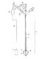
以下、この発明のバルーン付きアブレーションカテーテルの実施形態を説明する。図1は実施形態に係るアブレーションカテーテルの全体の構成を示す平面図、図2は実施形態のアブレーションカテーテルのバルーンの内部を示す断面図、図3は実施形態のアブレーションカテーテルのバルーンの膨張時の外形を示す正面図である。この実施形態のアブレーションカテーテルは、心臓不整脈治療としての肺静脈電気的隔離をおこなうのに好適なものである。 Hereinafter, embodiments of the ablation catheter with a balloon according to the present invention will be described. FIG. 1 is a plan view showing the overall configuration of the ablation catheter according to the embodiment, FIG. 2 is a cross-sectional view showing the inside of the balloon of the ablation catheter of the embodiment, and FIG. FIG. The ablation catheter of this embodiment is suitable for performing pulmonary vein electrical isolation as a treatment for cardiac arrhythmia.
実施形態のアブレーションカテーテルでは、カテーテル1の先端側に膨張・収縮可能なバルーン2が配置されている。カテーテル1は、外筒シャフト3と内筒シャフト4が軸方向移動可能に同心的に通し合わされている二重筒式カテーテルであり、バルーン2の先端部が内筒シャフト4の先端に固定され、バルーン2の後端部が外筒シャフト3の先端に固定されていて、バルーン後端に液体導入口2Aが設けられている。二重筒式となっているカテーテル1の場合、外筒シャフト3あるいは内筒シャフト4を軸方向に移動させることにより、バルーン2の形状を多様に変化させることができる。したがって、本発明では、カテーテル1が二重筒式カテーテルであることが好ましいが、カテーテル1は必ずしも二重筒式カテーテルに限られるものではなく、治療の種類によっては単一管式カテーテルが好ましいこともある。 In the ablation catheter of the embodiment, a
外筒シャフト3と内筒シャフト4の長さは、1m前後〜1m数十cm程度である。外筒シャフト3の外径は3mm〜5mm程度であり、内径は2mm〜4mm程度である。内筒シャフト4の外径は1mm〜3mm程度であり、内径は0.5mm〜2mm程度である。外筒シャフト3や内筒シャフト4の材料は、抗血栓性に優れる可撓性のある材料が用いられる。具体的には、例えばフッ素樹脂、ポリアミド樹脂、ポリイミド樹脂等が挙げられる。 The length of the
また、外筒シャフト3と内筒シャフト4の先端には、放射線遮蔽性金属パイプ3A,4Aが取り付けられていて、バルーン2の先端部や後端部は金属パイプ3A,4Aに取り付けられて外筒シャフト3と内筒シャフト4に固定されている。放射線遮蔽性金属パイプ3A,4Aを具備することにより、X線透視を行った場合、X線透視画像上に放射線遮蔽性金属パイプ3A,4Aが出現するので、患者体内におけるバルーン2の位置を正確に把握することが可能となる。放射線遮蔽性金属パイプ3A,4Aの材料としては、金,プラチナ,ステンレス等が挙げられる。 Further, radiation shielding
バルーン2は、図3に示すように、膨張状態において先端側で直径が小さくなる円錐状(先すぼみ円錐状)の外形を有している。バルーン2は、長さ(バルーン先端とバルーン後端を仮想的に結ぶバルーン中心軸2aに沿う長さd)が、20mm〜40mm程度であって、後端側の最大外直径が10mm〜40mm程度であり、膜厚みが100μm〜300μmである。バルーン2の外径が先すぼみの円錐状の外形である場合、バルーンが肺静脈内に入り込むのを防止できるうえ、バルーンの先端を肺静脈口に少し挿し込むことによりバルーンを肺静脈口にきっちり密着させられるので、肺静脈口の環状周縁部の全体を確実に焼灼することができる。バルーン2の材料は、抗血栓性に優れた伸縮性のある材料が用いられる。特にポリウレタン系の高分子材料が好ましく、具体的には、熱可塑性ポリエーテルウレタン,ポリエーテルポリウレタンウレア,フッ素ポリエーテルウレタンウレア,ポリエーテルポリウレタンウレア樹脂,ポリエーテルポリウレタンウレアアミド等が挙げられる。 As shown in FIG. 3, the
さらに、実施形態のアブレーションカテーテルの場合、電気導電性材の蒸着、メッキ、塗装の表面処理による膜のうちの少なくとも1つである導電被膜が面状の高周波通電用内電極(以下、適宜「内電極」と略記)5としてバルーン2の外周内面を全面的に覆って積層されている。面状の内電極5の膜厚みは数ミクロン〜十数ミクロン程度であり、面状の内電極5の電気導電性材には、金や銀あるいはプラチナ,銅やアルミニウム等が用いられる。なお、面状の内電極5の対電極として別途に患者体外の適当な位置にセットされる高周波通電用外電極(以下、適宜「外電極」と略記)7には、面状の電極が用いられる。外電極7の材料には、銅やアルミニウムの高導電率金属薄板が挙げられる。面状の内電極5と外電極7の間で高周波通電が行われることにより、高周波誘電加熱およびジュール熱による加温がおこなわれる。高周波誘電加熱およびジュール熱による加温の際の適温は、通常、50℃〜70℃の範囲にある。 Furthermore, in the case of the ablation catheter of the embodiment, the conductive film, which is at least one of the films formed by the surface treatment of vapor deposition, plating, and coating of an electrically conductive material, is a planar high frequency energizing inner electrode (hereinafter referred to as “inner The
また、実施形態のアブレーションカテーテルでは、バルーン2の内に液体導入口2Aから液体をカテーテル1経由で送給する液体送給装置(液体送給手段)6がカテーテル1の末端側に四方コネクタCNを介して接続配設されている。液体送給装置6は、送液用ローラポンプ(図示省略)を備えていて、送液用ローラポンプにより送給される液体が外筒シャフト3と内筒シャフト4の間のクリアランスを通って液体導入口2Aからバルーン2の内に送り込まれる。液体送給装置6からの液体がバルーン2の内に送り込まれるのに伴ってバルーン2は膨張する。つまり、外筒シャフト3と内筒シャフト4の間のクリアランスが液体送給装置6による液体送給用の流路として利用されているのである。 In the ablation catheter of the embodiment, the liquid feeding device (liquid feeding means) 6 for feeding the liquid into the
さらに、実施形態のアブレーションカテーテルでは、液体送給装置6による液体送給により膨張状態にあるバルーン2の内において温度を検出する温度センサ8がバルーン2の内側に配置されているのに加え、温度センサ8の測温結果に応じた供給量で高周波電力を供給する高周波電源(電力供給手段)9がカテーテル1の末端側に四方コネクタCNを介して接続配設されている。高周波電力の周波数は数MHz〜数百MHz、通常、十数MHzである。 Furthermore, in the ablation catheter of the embodiment, the
高周波誘電加熱およびジュール熱による加温実行中、加温温度がバルーン2内の温度センサ8によって検出されて高周波電源9へフィードバックされると共に、高周波電源9により温度センサ8の測温結果に応じた供給量で高周波電力が供給されることによって、高周波誘電加熱およびジュール熱による加温温度がコントロールされる。なお、温度センサ8としては、熱電対が例示されるが、熱電対に限られるものではなく、例えば半導体タイプの測温素子なども使用可能である。温度センサ8は、外筒シャフト3に接続されている金属パイプ3Aに固定されているセンサ支持バー9Aによってバルーン2の中心寄りに支持されている。 During the execution of heating by high-frequency dielectric heating and Joule heat, the heating temperature is detected by the
また、図4に示すように、温度センサ8から測温信号を取り出すセンサ用リード線10と面状の高周波通電用内電極5に高周波電力を送給する電力送給用リード線11は共に電気絶縁性保護被覆12,13付きでカテーテル1の外筒シャフト3と内筒シャフト4の間のクリアランスに引き通されている。つまり、外筒シャフト3と内筒シャフト4の間のクリアランスをセンサ用リード線10や電力送給用リード線11の配管として利用されているのである。電力送給用リード線11は金属パイプ3Aを介して面状の内電極5に接続されている。即ち、電力送給用リード線11は金属パイプ3Aに取り付けられている一方、面状の内電極5の末端部が金属パイプ3Aに外挿されたかたちで取り付けられることにより金属パイプ3Aが接続端子となって電力送給用リード線11が面状の内電極5とを電気的に繋ぐのである。なお、面状の内電極5の末端部は、電気導電性材の蒸着、メッキ、塗装の不足や膜の補強などの為に導電性ペーストを膜形成後に、さらに塗布するようにしてもよい。 Further, as shown in FIG. 4, both the
センサ用リード線10と電力送給用リード線11は共に電気絶縁性保護被覆12,13付きであるので、リード線同士のショート(短絡)が起こる心配がなくなると同時に、高周波電力の漏れ・侵入が抑えられ、高周波電力の漏れ・侵入による外筒シャフト3や内筒シャフト4の発熱が抑えられる結果、実施形態のアブレーションカテーテルの場合、カテーテル1の強制冷却機構が省かれている。しかし、必要に応じてカテーテル1の強制冷却機構をカテーテル1に内設してもよい。 Since both the
センサ用リード線10や電力送給用リード線11の材料としては、銅,銀,白金,タングステン,合金などの線材が挙げられる。また、電気絶縁性保護被覆12,13がポリ塩化ビニルより比誘電率の小さい材料からなる場合は、電気絶縁性保護被覆12,13の電気絶縁性が向上するので、高周波電力の漏れ・侵入がいっそう抑えられ、高周波電力の漏れ・侵入による外筒シャフト3や内筒シャフト4の発熱がしっかり抑えられる。また、外筒シャフト3や内筒シャフト4がポリ塩化ビニルより比誘電率の小さい材料からなることも、高周波電力の漏れ・侵入による外筒シャフト3や内筒シャフト4の発熱を防止する上で有効である。 Examples of the material of the
ポリ塩化ビニルより比誘電率の小さい材料としては、10MHzの比誘電率が3以下、さらに好ましくは10MHzの比誘電率が1以下のものが挙げられる。この比誘電率εは、以下のようにして測定できる。 As a material having a relative dielectric constant smaller than that of polyvinyl chloride, a material having a relative dielectric constant of 10 MHz at 3 or less, more preferably 10 MHz at a relative dielectric constant of 1 or less can be mentioned. This relative dielectric constant ε can be measured as follows.
ε=Cx/Co
但し、Cxはブリッジが平衡になった時の測定用コンデンサCsの容量
但し、Coは主電極の面積及び試験片の厚さから算出したε=1の静電容量で次の式で算出する。ε = Cx / Co
Where Cx is the capacitance of the measuring capacitor Cs when the bridge is balanced. However, Co is a capacitance of ε = 1 calculated from the area of the main electrode and the thickness of the test piece, and is calculated by the following equation.
Co=r2 /3.6t
r:主電極の半径(cm),t:試験片の厚さ(cm)
ポリ塩化ビニルより比誘電率の小さい材料の具体的なものには、ポリ4フッ化エチレン(PTFE)や4フッ化エチレン−6フッ化プロピレン共重合体(FEP)などのフッ素系高分子化合物の他、ポリエチレン,ポリプロピレン,ポリイミド樹脂,ポリアミド樹脂などが挙げられる。なお、比誘電率εの測定に用いられる機器としては、例えばヒューレットパッカード社製のRFインピーダンス/マテリアルアナライザ(HP4291A)が挙げられる。Co = r2 /3.6t
r: radius of main electrode (cm), t: thickness of test piece (cm)
Specific examples of materials having a lower dielectric constant than polyvinyl chloride include fluorine polymer compounds such as polytetrafluoroethylene (PTFE) and tetrafluoroethylene-6-fluoropropylene copolymer (FEP). Other examples include polyethylene, polypropylene, polyimide resin, and polyamide resin. In addition, as an apparatus used for the measurement of the dielectric constant ε, for example, an RF impedance / material analyzer (HP4291A) manufactured by Hewlett-Packard Company may be used.
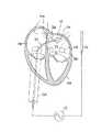
なお、実施形態のアブレーションカテーテルを用いて肺静脈口の環状周縁部を焼灼する場合は、従来の場合と同様、図5に示すように、先に経皮的に患者体内に導入したガイドワイヤGWに沿ってバルーン2をカテーテル1で押し進めながら下大静脈から左心房へ到達させた後、膨張状態のバルーン2を肺静脈口Qaに当てがって密着させておき、面状の内電極5と外電極7の間で高周波通電を行わせて肺静脈口Qaの環状周縁部を焼灼する。 In the case of cauterizing the annular peripheral edge of the pulmonary vein opening using the ablation catheter of the embodiment, as in the conventional case, as shown in FIG. 5, the guide wire GW previously introduced into the patient's body percutaneously. The
以上に述べた実施形態のアブレーションカテーテルでは、面状の高周波通電用内電極5がバルーン2の外周内面を全面的に覆っていて、標的病変部位を焼灼する場合、標的病変部位がバルーン2の外周表面の何処に密着していても、標的病変部位の密着個所は全域が一律にバルーン2の膜だけを隔てて面状の内電極5と対置するという状態になるので、高周波誘電加熱およびジュール熱による給熱が標的病変部位のバルーン密着個所全体にわたって確実に均一に行えるのに加え、面状の内電極5はバルーン2の内面に積層形成されていて、面状の内電極5が結構大きくても、バルーンの膜の厚みが少し増す程度のことだけで、何ら支障をもたらさない。 In the ablation catheter of the above-described embodiment, when the planar high-frequency energizing
よって、実施形態のバルーン付きアブレーションカテーテルによれば、高周波誘電加熱およびジュール熱による加温ムラを確実に解消することができる。加えて、実施形態の場合、面状の内電極5が電気導電性材の蒸着、メッキ、塗装の表面処理による膜のうちの少なくとも1つであるので、面状の内電極5は膨張・収縮するバルーン2の膜の動きによく追随してバルーンの膨張・収縮を妨げず、バルーン2の膨張・収縮によって面状の内電極5が剥離することも避けられる。 Therefore, according to the ablation catheter with a balloon of the embodiment, heating unevenness due to high-frequency dielectric heating and Joule heat can be reliably solved. In addition, in the case of the embodiment, since the planar
続いて、本発明の具体的な実施例について説明する。 Next, specific examples of the present invention will be described.
〔実施例〕 先ず、バルーン先端とバルーン後端の長さが30mm、後端側の最大外直径が30mm、膜厚みが160μmの先すぼみの円錐形状を有するバルーン2を次のようにして作成した。即ち、所望のバルーン形状に対応する型面を有するガラス製バルーン成形型を濃度13%のポリウレタン溶液に浸漬し、熱をかけて溶媒を蒸発させて、成形型表面にウレタンポリマー被膜を形成するディッピング法によりバルーン2を作製した。続いて、作製したバルーン2の外周内面へ厚み10μmで全面的に銀を真空蒸着すると共にバルーン2の後端内面に銀ペーストを塗布して補強し、面状の高周波通電用内電極5を設置した。 [Example] First, a
一方、カテーテル1の外筒シャフト3として外径3.8mm、内径2.7mm、全長80cmのポリアミド樹脂製チューブを用い、直径3.1mm、長さ7mmでサンドブラスト仕上げの外表面を有するステンレスパイプを金属パイプ3Aとしてチューブの先端に内挿嵌着した後0.1mmのナイロン製糸で縛り固定すると共に、後端に四方コネクタCNを内挿嵌合した後0.1mmのナイロン製糸で縛り固定した。 On the other hand, a polyamide resin tube having an outer diameter of 3.8 mm, an inner diameter of 2.7 mm, and an overall length of 80 cm is used as the outer
他方、内筒シャフト4として外径1.5mm、内径1.1mm、全長90cmのポリアミド樹脂製チューブを用い、直径1.2mm、長さ6mmでサンドブラスト仕上げの外表面を有するステンレスパイプを金属パイプ4Aとしてチューブの先端に内挿嵌着後0.1mmのナイロン製糸で縛り固定した。そして、内筒シャフト4を四方コネクタCNを介して挿入してから四方コネクタCNのキャップを締め付けることにより二重筒式のカテーテル1を作製した。また、温度センサ8として、ポリ4フッ化エチレンの電気絶縁性保護被膜13を施した極細熱電対ダブル(銅−コンスタンタン)線をセンサ用リード線10付きのものとして作製すると共に、電力送給用リード線11として、4フッ化エチレン−6フッ化プロピレン共重合体(FEP)の電気絶縁性保護被覆13を施した銅線を作製した。 On the other hand, a polyamide resin tube having an outer diameter of 1.5 mm, an inner diameter of 1.1 mm, and an overall length of 90 cm is used as the inner
次に温度センサ8をセンサ支持バー9Aで金属パイプ3Aに固定した後、電力送給用リード線11の先端を金属パイプ3Aに接続してから、センサ用リード線10と電力送給用リード線11を外筒シャフト3と内筒シャフト4の間のクリアランスを引き通してセンサ用リード線10と電力送給用リード線11の後端を四方コネクタCNより引っ張り出した。最後に、バルーン2の先端部を金属パイプ4Aに0.1mmのナイロン製糸で縛り固定すると共に、バルーン2の後端部を金属パイプ3Aに0.1mmのナイロン製糸で縛り固定して、実施例のアブレーションカテーテルを完成した。 Next, after the
〔比較例〕 比較例について説明する。面状の内電極5の代わりに、図6に示すように、銀メッキを0.1μm施した直径0.5mmの電気用軟銅線の先端部分を内径1.7mm、長さ10mmにわたって巻き回したコイル状の高周波通電用内電極15を内筒シャフト4に嵌挿した状態で設置した他は、実施例と同様にして比較例のアブレーションカテーテルを作製した。 [Comparative Example] A comparative example will be described. Instead of the planar
〔加温テスト〕 次に作製した実施例と比較例のアブレーションカテーテルについて、それぞれ高周波通電を行い、高周波誘電加熱およびジュール熱による加温テストを行った。生理食塩水を十分大きな水槽(図示省略)に入れて攪拌機能付きヒータで37℃の液温にすると共に、外電極を容器の周壁表面にセットした。そして、実施例のアブレーションカテーテルのバルーン2をカテーテル1ごと水槽に入れた。一方、センサ用リード線10を高周波電源9の測温信号入力端子に接続すると共に、面状の内電極5の電力送給用リード線11と外電極7の電力送給用リード線14を高周波電源9の高周波電力出力端子にそれぞれ接続した。高周波電源9は、温度センサ8の測温信号の強度に応じて加温温度が70℃となるように高周波電力の供給量を制御するようにセットされている。高周波電力の周波数は約13.6MHzである。 [Heating test] Next, the ablation catheters of Examples and Comparative Examples produced were each subjected to high-frequency energization, and subjected to a heating test using high-frequency dielectric heating and Joule heat. Physiological saline was placed in a sufficiently large water tank (not shown), and the liquid temperature was 37 ° C. with a heater with a stirring function, and the outer electrode was set on the peripheral wall surface of the container. And the
また、液体送給装置6を四方コネクタCNに接続し液体として造影剤をカテーテル1経由でバルーン2に送り込んでバルーン2を膨らませて、高周波電源9から高周波電力を供給した。そして、高周波電力の供給中、加温温度のコントロール状況をチェックする為に測温信号の強度を記録した。また、加温ムラのチェックの為に、バルーン2の先端と中央の間のところを周方向に沿って60°置きに微小温度センサを各一個ずつ配置し、加温温度安定期に入ってからバルーン2の外周表面の温度を測定した。 Further, the liquid feeding device 6 was connected to the four-way connector CN, and a contrast medium was fed as a liquid to the
次に比較例のアブレーションカテーテルについても、実施例と全く同様、測温信号の強度を記録すると共に、加温温度安定期に入ってからバルーン2の外周表面の温度を測定した。 Next, for the ablation catheter of the comparative example, the intensity of the temperature measurement signal was recorded as in the example, and the temperature of the outer peripheral surface of the
そして、実施例と比較例のテストの結果を評価した。測温信号強度の記録結果から、実施例と比較例のアブレーションカテーテルは、いずれも加温温度のコントロールについては差がなかった。しかし、バルーン2の外周表面の6個の測定温度のバラツキは、実施例の場合6個全ての温度が約58℃であったのに対し、比較例の場合、上部の温度センサほど測温した温度は高く、最上部の温度センサで測温した温度と最下部の温度センサで測温した温度との差は約15℃であった。従って、実施例のアブレーションカテーテルの場合、加温が均一に行われていることが分かった。即ち、実施例のバルーン付きアブレーションカテーテルによれば、高周波誘電加熱およびジュール熱による加温ムラが確実に解消させられることが裏付けられた。 And the result of the test of an Example and a comparative example was evaluated. From the recorded results of the temperature measurement signal intensity, the ablation catheters of the example and the comparative example were not different from each other in controlling the heating temperature. However, the variation in the six measured temperatures on the outer peripheral surface of the
この発明は、上記の実施例に限られるものではなく、以下のように変形実施することも可能である。 The present invention is not limited to the above embodiment, and can be modified as follows.
(1)実施形態のアブレーションカテーテルは、液体送給装置6や高周波電源9あるいは外電極7も全て備えた構成であったが、液体送給装置6や高周波電源9あるいは外電極7は実際に使用する際に別途調達することが可能であるので、本発明のアブレーションカテーテルは、液体送給装置6や高周波電源9あるいは外電極7は備えていないカテーテル1およびバルーン2から四方コネクタCNまでの構成のものであってもよい。 (1) The ablation catheter of the embodiment has a configuration including all of the liquid feeding device 6, the high-
(2)実施形態のアブレーションカテーテルは、面状の高周波通電用内電極5がバルーン2の外周内面を全面的に覆っている構成であったが、面状の内電極5は必ずしもバルーン2の外周内面を全面的に覆っていなくても、バルーン2の外周内面のうち少なくとも先端側半分以上を覆っている構成のものであれば、標的病変部位を焼灼する場合、バルーン2の先端側の外周表面を標的病変部位へ密着させることが多いので、十分に有用である。 (2) The ablation catheter according to the embodiment has a configuration in which the planar high-frequency energizing
(3)実施形態のアブレーションカテーテルは、面状の高周波通電用内電極5が蒸着膜であったが、面状の高周波通電用内電極5が電気導電性材のメッキ、塗装、金属箔である他は実施形態と同一であるものを、変形例として挙げることができる。 (3) In the ablation catheter of the embodiment, the planar high-frequency energization
1 … カテーテル
2 … バルーン
3 … 外筒シャフト
4 … 内筒シャフト
5 … 面状の高周波通電用内電極
6 … 液体送給装置(液体送給手段)
7 … 高周波通電用外電極
8 … 温度センサ
9 … 高周波電源(電力供給手段)
10 … センサ用リード線
11 … 電力送給用リード線
12,13 … 電気絶縁性保護被覆
14 … 電力送給用リード線
15 … コイル状の高周波通電用内電極
DESCRIPTION OF SYMBOLS 1 ...
7 ... outer electrode for high-
DESCRIPTION OF
Claims (11)
Translated fromJapaneseThe ablation catheter with a balloon according to claim 10, wherein the liquid fed by the liquid feeding means passes through a clearance between the outer cylinder shaft and the inner cylinder shaft.
Priority Applications (1)
| Application Number | Priority Date | Filing Date | Title |
|---|---|---|---|
| JP2003293100AJP2005058507A (en) | 2003-08-13 | 2003-08-13 | Ablation catheter with balloon |
Applications Claiming Priority (1)
| Application Number | Priority Date | Filing Date | Title |
|---|---|---|---|
| JP2003293100AJP2005058507A (en) | 2003-08-13 | 2003-08-13 | Ablation catheter with balloon |
Publications (1)
| Publication Number | Publication Date |
|---|---|
| JP2005058507Atrue JP2005058507A (en) | 2005-03-10 |
Family
ID=34370209
Family Applications (1)
| Application Number | Title | Priority Date | Filing Date |
|---|---|---|---|
| JP2003293100APendingJP2005058507A (en) | 2003-08-13 | 2003-08-13 | Ablation catheter with balloon |
Country Status (1)
| Country | Link |
|---|---|
| JP (1) | JP2005058507A (en) |
Cited By (2)
| Publication number | Priority date | Publication date | Assignee | Title |
|---|---|---|---|---|
| WO2007052341A1 (en)* | 2005-11-01 | 2007-05-10 | Japan Electel Inc. | Balloon catheter system |
| WO2021201078A1 (en)* | 2020-03-31 | 2021-10-07 | 東レ株式会社 | Balloon catheter and balloon catheter system |
- 2003
- 2003-08-13JPJP2003293100Apatent/JP2005058507A/enactivePending
Cited By (4)
| Publication number | Priority date | Publication date | Assignee | Title |
|---|---|---|---|---|
| WO2007052341A1 (en)* | 2005-11-01 | 2007-05-10 | Japan Electel Inc. | Balloon catheter system |
| US8226637B2 (en) | 2005-11-01 | 2012-07-24 | Japan Electel, Inc. | Balloon catheter system |
| WO2021201078A1 (en)* | 2020-03-31 | 2021-10-07 | 東レ株式会社 | Balloon catheter and balloon catheter system |
| JPWO2021201078A1 (en)* | 2020-03-31 | 2021-10-07 |
Similar Documents
| Publication | Publication Date | Title |
|---|---|---|
| CN1901844B (en) | Balloon catheter | |
| JP6259099B2 (en) | Balloon catheter comprising a conductive wire with flexibility, and related uses and manufacturing methods | |
| JP5444840B2 (en) | Ablation catheter with balloon and ablation catheter system with balloon | |
| US10660703B2 (en) | Renal nerve modulation devices | |
| EP2719350B1 (en) | Ablation catheter with balloon | |
| JP5870694B2 (en) | Potential measurement catheter | |
| JP6499163B2 (en) | Medical instruments | |
| JP2016185296A (en) | Balloon type ablation catheter | |
| JP4222152B2 (en) | Ablation catheter with balloon | |
| JP4062935B2 (en) | Ablation catheter with balloon | |
| JP4618237B2 (en) | Ablation catheter system with balloon with adjustable temperature rise time | |
| JP2005058507A (en) | Ablation catheter with balloon | |
| JP2005192725A (en) | Ablation catheter with balloon | |
| JP2004305250A (en) | Device and method for treatment of cardiac arrhythmias | |
| JP4140483B2 (en) | Ablation catheter with balloon | |
| JP2006198209A (en) | Ablation catheter with balloon | |
| JP2004073570A (en) | Balloon catheter for electrical separation of pulmonary vein | |
| JP2004305251A (en) | Balloon catheter for electrical pulmonary vein isolation | |
| JP2004180892A (en) | Ablation catheter | |
| JP2005058504A (en) | Ablation catheter with balloon | |
| JP2005058503A (en) | Ablation catheter with balloon | |
| JP2005058505A (en) | Ablation catheter with balloon for cardiac arhythmia treatment | |
| WO2022259438A1 (en) | Balloon-type electrode catheter |