JP2005052914A - Electric drilling device with automatic redrive function - Google Patents
Electric drilling device with automatic redrive functionDownload PDFInfo
- Publication number
- JP2005052914A JP2005052914AJP2003284837AJP2003284837AJP2005052914AJP 2005052914 AJP2005052914 AJP 2005052914AJP 2003284837 AJP2003284837 AJP 2003284837AJP 2003284837 AJP2003284837 AJP 2003284837AJP 2005052914 AJP2005052914 AJP 2005052914A
- Authority
- JP
- Japan
- Prior art keywords
- reference value
- load current
- current
- turned
- electric drill
- Prior art date
- Legal status (The legal status is an assumption and is not a legal conclusion. Google has not performed a legal analysis and makes no representation as to the accuracy of the status listed.)
- Granted
Links
Images

Landscapes
- Drilling And Boring (AREA)
- Perforating, Stamping-Out Or Severing By Means Other Than Cutting (AREA)
Abstract
Translated fromJapaneseDescription
Translated fromJapanese本発明は、自動再駆動機能付き電動ドリル装置に関し、より詳細には、過負荷時にドリルモータの回転を停止させた場合に、該ドリルモータを自動的に再駆動できるようにした電動ドリル装置に関する。 The present invention relates to an electric drill apparatus with an automatic redrive function, and more particularly, to an electric drill apparatus that can automatically redrive the drill motor when rotation of the drill motor is stopped during an overload. .
本出願人は、電動ドリル装置において、環状刃物を回転させるドリルモータの過負荷状態を電気的に検出して電動ドリル装置を保護する手法を既に提案し実用化している。その例が以下の特許文献1及び2に記載されており、これら従来例の電動ドリル装置においては、ドリルモータに流れる電流を監視し、該電流値が第1の基準値に到達したときに、送りモータの駆動を停止し、電流値が第1の基準値よりも大きい第2の基準値に到達したときに、送りモータ及びドリルモータの両方の駆動を停止させるよう構成されている。
これにより、モータを保護することができるとともに、電動ドリル装置の横滑り又は振動が生じる前にモータを停止させることができるため、電動ドリル装置による振り回されを防止することができ、また、環状刃物の刃先及び本体の破損を防止することができる。
As a result, the motor can be protected and the motor can be stopped before the side drilling or vibration of the electric drill apparatus occurs, so that the electric drill apparatus can be prevented from being swung around, and Breakage of the blade edge and the main body can be prevented.
上記したように、過負荷時の自動停止機能を備えている電動ドリル装置が既に提案されているが、このような従来例においては、過負荷により停止させたドリルモータを再駆動するためには、作業員が起動スイッチを手動操作する必要がある。このため、極めて作業性が悪い。
特に、ドリルを自動的に下方に移動させるための送りモータを具備していない電動ドリル装置においては、ドリルを再駆動するためには、手動でドリル移動用のハンドルを回動操作しつつ、ドリルモータの起動スイッチを操作しなければならないため、作業員に大きな負担がかかっている。As described above, an electric drill device having an automatic stop function at the time of overload has already been proposed. In such a conventional example, in order to re-drive a drill motor stopped by an overload. The operator needs to manually operate the start switch. For this reason, workability | operativity is very bad.
In particular, in an electric drill apparatus that does not include a feed motor for automatically moving the drill downward, in order to re-drive the drill, the drill moving handle is manually rotated and the drill is moved. Since the motor start switch has to be operated, a heavy burden is placed on the worker.
本発明は、このような従来例の問題点に鑑みてなされたものであり、その目的は、電動ドリル装置において、過負荷時に自動停止したドリルモータを、簡単な構成で自動的に再駆動することができるようにすることである。
本発明の他の目的は、電動ドリル装置において、ドリルモータが正常に再駆動してドリルが正常に回転したときに、それを報知することにより、穿孔作業を再開可能であることを、作業員が容易に知ることができるようにすることである。The present invention has been made in view of the above-described problems of the conventional example, and an object of the present invention is to automatically redrive a drill motor that is automatically stopped at an overload with a simple configuration in an electric drill apparatus. Is to be able to.
Another object of the present invention is that in an electric drill apparatus, when a drill motor is re-driven normally and the drill rotates normally, a drilling operation can be resumed by notifying the operator that the drill has rotated normally. Is to be able to know easily.
上記した目的を達成するために、本発明に係る、被加工物に穿孔するための電動ドリル装置は、
電動ドリルの環状刃物を回転させるためのドリルモータと、
ドリルモータと電源との間に直列接続された主スイッチング素子と、
ドリルモータに流れる負荷電流を検出する電流検出手段と、
電流検出手段によって検出された負荷電流が所定の第1の基準値を超えたかどうかを判定する第1の判定手段と、
主スイッチング素子のオン/オフを制御する制御手段であって、第1の判定手段が負荷電流が第1の基準値を超えたと判定したときに、主スイッチング素子をオフにしてドリルモータに流れる電流を遮断するよう制御し、その後、第1の判定手段が負荷電流が第1の基準値より小さくなったと判定したときに、その判定から所定時間後に、主スイッチング素子をオンにしてドリルモータに電源から電流を供給するよう制御する制御手段と
からなることを特徴としている。In order to achieve the above-described object, an electric drill apparatus for drilling a workpiece according to the present invention includes:
A drill motor for rotating the annular blade of the electric drill;
A main switching element connected in series between the drill motor and the power supply;
Current detecting means for detecting a load current flowing in the drill motor;
First determination means for determining whether or not the load current detected by the current detection means exceeds a predetermined first reference value;
Control means for controlling on / off of the main switching element, and when the first determination means determines that the load current has exceeded the first reference value, the current flowing through the drill motor with the main switching element turned off Then, when the first determination means determines that the load current has become smaller than the first reference value, the main switching element is turned on and power is supplied to the drill motor after a predetermined time from the determination. It is characterized by comprising control means for controlling to supply current from
上記した本発明に係る電動ドリル装置はさらに、電流検出手段によって検出された負荷電流が、第1の基準値よりも低い第2の基準値を超えたかどうかを判定する第2の判定手段と、第2の判定手段が、負荷電流が第2の基準値を超えていないと判定したときに、正常な負荷電流であることを示す表示を行い、負荷電流が第2の基準値を超えたと判定したときに警報表示を行う負荷状態表示手段とを備えていることが好ましい。
また、一実施形態では、電流検出手段は、ドリルモータ及び主スイッチング素子に直列接続された固定抵抗であって、該固定抵抗の両端から負荷電流に対応する電圧を出力するよう構成されており、第1の判定手段は、負荷電流に対応する電圧を受け取り、該電圧を、第1の基準値を電圧に変換した第1の電圧基準値と対比することにより、負荷電流が第1の基準値を超えたか否かを判定するよう構成されている。そして、第2の判定手段は、負荷電流に対応する電圧を受け取り、該電圧を、第2の基準値を電圧に変換した第2の電圧基準値と対比することにより、負荷電流が第2の基準値を超えたか否かを判定するよう構成されている。The electric drill apparatus according to the present invention described above further includes second determination means for determining whether or not the load current detected by the current detection means exceeds a second reference value lower than the first reference value; When the second determination means determines that the load current does not exceed the second reference value, it displays that the load current is normal, and determines that the load current exceeds the second reference value. It is preferable to include a load state display means for displaying an alarm when a failure occurs.
In one embodiment, the current detection means is a fixed resistor connected in series to the drill motor and the main switching element, and is configured to output a voltage corresponding to the load current from both ends of the fixed resistor. The first determination means receives a voltage corresponding to the load current, and compares the voltage with a first voltage reference value obtained by converting the first reference value into a voltage, so that the load current becomes the first reference value. It is comprised so that it may be determined whether it exceeded. The second determination means receives a voltage corresponding to the load current, and compares the voltage with a second voltage reference value obtained by converting the second reference value into a voltage, so that the load current becomes the second voltage. It is configured to determine whether or not a reference value has been exceeded.
上記した本発明に係る電動ドリル装置において、一実施形態においては、制御手段は、ドリルモータの駆動を開始させるための起動スイッチがオンされたときに、オン状態を自己保持する第1のスイッチング素子と、第1のスイッチング素子がオン状態のときに、主スイッチング素子をオン状態にするオン制御信号を供給する制御信号供給手段と、第1の判定手段が負荷電流が第1の基準値を超えたと判定したときにターンオンして、第1のスイッチング素子のオン状態に拘わらず、制御信号供給手段からオン制御信号が発生されないようにする第2のスイッチング素子と、第1の判定手段が、負荷電流が第1の基準値を超えたと判定してから該基準値より小さくなったと判定したときに、その判定から所定時間後に、第2のスイッチング素子をターンオフさせる手段とから構成されている。 In the above-described electric drill apparatus according to the present invention, in one embodiment, the control means is a first switching element that self-holds an on state when a start switch for starting driving of the drill motor is turned on. And a control signal supply means for supplying an ON control signal for turning on the main switching element when the first switching element is in the ON state, and the first determination means has a load current exceeding the first reference value. A second switching element that is turned on when it is determined that the control signal supply means does not generate an on control signal regardless of whether the first switching element is on, and the first determination means includes a load When it is determined that the current has become smaller than the reference value after determining that the current has exceeded the first reference value, the second switching element after a predetermined time from the determination. It is composed of a means for turning off the.
上記した本発明に係る電動ドリル装置において、一実施形態においては、主スイッチング素子はトライアックであり、制御手段は、ドリルモータの駆動を開始させるための起動スイッチがオンされたときに、オン状態を自己保持する第1のスイッチングトランジスタと、第1のスイッチングトランジスタがオン状態のときに電流が流れて発光するフォトダイオードと、トライアックのゲートとアノード又はカソードとの間に接続されたフォトトライアックであって、フォトダイオードに光結合されて該フォトダイオードの発光によりオン状態となることによりトライアックにゲート電流を供給するフォトトライアックと、第1の判定手段が、負荷電流が第1の基準値を超えたと判定したときに、第1のスイッチングトランジスタのオン状態に拘わらず、フォトダイオードの電流をバイパスして消光させる第2のスイッチングトランジスタと、第1の判定手段が、負荷電流が第1の基準値を超えたと判定してから該基準値より小さくなったと判定したときに、その判定から所定時間後に、第2のスイッチングトランジスタをターンオフさせる手段とから構成されている。 In the above-described electric drill apparatus according to the present invention, in one embodiment, the main switching element is a triac, and the control means turns on when an activation switch for starting driving of the drill motor is turned on. A first switching transistor that self-holds; a photodiode that emits light when a first switching transistor is in an on state; and a phototriac connected between a gate and an anode or cathode of the triac. The phototriac that is optically coupled to the photodiode and is turned on by light emission of the photodiode and supplies the gate current to the triac, and the first determination means determines that the load current has exceeded the first reference value When the first switching transistor is turned on Regardless, the second switching transistor that bypasses the photodiode current and extinguishes, and the first determination means determines that the load current has exceeded the first reference value, and then determines that the load current has decreased below the reference value And a means for turning off the second switching transistor after a predetermined time from the determination.
本発明は、上記した構成を有しているので、ドリルモータが過負荷時に自動的に停止した場合、所定時間後にドリルモータを自動的に再駆動することができ、もって作業性が向上する。
また、ドリルモータの再駆動が正常に行われた場合に、それを作業員に報知することができるので、作業員は、ドリルの下方移動の開始可能時点を容易に知ることができる。Since the present invention has the above-described configuration, when the drill motor is automatically stopped when overloaded, the drill motor can be automatically re-driven after a predetermined time, thereby improving workability.
Moreover, when the re-driving of the drill motor is normally performed, this can be notified to the worker, so that the worker can easily know when the drill can start moving downward.
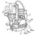
図1は、本発明に係る電動ドリル装置の一実施例の外観斜視図を示しており、図2は、その右側面図を示している。また、図3は、図1及び図2に示した電動ドリル装置の回路図である。
電動ドリル装置の本体1の下端には、内部に電磁石20(図3)を備えた電磁ベース2が設けられており、側面には側面に沿って上下方向に移動可能なスライド板36が設けられている。スライド板36には、電動ドリル3が支持されている。本体1にはハンドルが取り付けられているとともに、本体1内にはスライド板36を上下させるためのドリル送り部4が配置され、ハンドル39を手動回動させると、ドリル送り部4中の伝達機構を介して、電動ドリル3を上下動させることができる。なお、ドリル送り部4中にモータを内蔵させ、該モータの回転をクラッチを介して伝達機構に伝達するよう構成してもよい。これにより、クラッチを外すか否かを選択操作することにより、電動ドリル3を手動又は電動の何れかで下方移動させることができる。FIG. 1 is an external perspective view of an embodiment of an electric drill apparatus according to the present invention, and FIG. 2 is a right side view thereof. FIG. 3 is a circuit diagram of the electric drill apparatus shown in FIGS. 1 and 2.
An
電動ドリル3は、ACモータであるドリルモータ30(図3)を内蔵しており、該ドリルモータ30の回転により、スピンドル11に装着された環状刃物5を回転させる。環状刃物5には、センタピン5aが環状刃物5の下面から出没自在に設けられている。スピンドル11は、本体1の下端部から側方に延びているブラケット12により、上下動可能に支持される。 The
本体1の正面に設けられた電源スイッチSWPWをオンさせると、電磁石ベース2中の電磁石20に通電されることにより、電動ドリル装置が被加工体に固定される。そして、瞬時/再駆動型である起動スイッチSWONをオンさせると、ドリルモータ30が駆動を開始し、電動ドリル3の環状刃物5が回転を開始する。この時点で、ハンドル39を手動で回動操作すると、電動ドリル3が下方すなわち被加工体の方向に移動される。これにより、電動ドリル3の環状刃物5が回転しつつ被加工体中を進み、被加工体に穿孔を形成することができる。
本体1の正面にはさらに、瞬時復帰型の停止スイッチSWOFFが設けられており、該スイッチをオンさせると、ドリルモータ30の駆動を停止させることができる。When the power switch SWPW provided on the front surface of the
Further, an instantaneous return type stop switch SWOFF is provided on the front surface of the
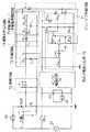
次に、図3を参照して、本発明に係る電動ドリル装置におけるドリルモータ30の駆動/停止のための回路構成及びその動作を説明する。
図3において、50はAC電源、51は全波整流回路、52はAC/DC電源回路である。電源スイッチSWPWがオンされると、全波整流回路51はAC電源50の電圧を全波整流して電磁石20に供給し、上記したように電動ドリル装置が被加工体に固定される。一方、AC/DC電源回路52は、AC電源50の電圧を定電圧のDC電圧(例えば、24V)に変換して、ドリルモータ30の駆動を制御するための制御部にDC電源を供給する。
BCRは、ドリルモータ30をAC電源50に接続/遮断するためのトライアック(主スイッチング素子)であり、該トライアックBCRのゲートとアノード(又はカソード)間には、フォトトライアックが接続されている。トライアックBCRには、負荷電流を検出するための抵抗(電流検出抵抗)R0が直列接続されている。Next, with reference to FIG. 3, the circuit configuration and operation for driving / stopping the
In FIG. 3, 50 is an AC power supply, 51 is a full-wave rectifier circuit, and 52 is an AC / DC power supply circuit. When the power switch SWPW is turned on, the full-wave rectification circuit 51 performs full-wave rectification on the voltage of the
The BCR is a triac (main switching element) for connecting / disconnecting the
DC電源電圧が印加される制御部には、オン/オフ制御回路71、増幅回路72、平滑回路73、過負荷判定回路74、自動停止/再駆動制御回路75、及び負荷状態表示回路76が含まれている。
オン/オフ制御回路71は、起動スイッチSWON及び停止スイッチSWOFFの手動操作に応じて、また、自動停止/再駆動制御回路75の出力に応じて、トライアックBCRのオン/オフを制御するため制御信号を出力するものである。
増幅回路72は、電流検出抵抗R0の両端の電圧を増幅して、平滑回路73に出力する。増幅回路72は、出力インピーダンスが小さく(ほぼゼロ)、電流検出抵抗R0の両端の電圧がゼロレベルに降下したときに、平滑回路73のコンデンサC73の充電電荷を、抵抗R73を介して急速放電させる。
増幅回路72の利得は1であってもよい。The control unit to which the DC power supply voltage is applied includes an on /
The on / off
The amplifier circuit 72 amplifies the voltage across the current detection resistor R0 and outputs the amplified voltage to the smoothing circuit 73. The amplifier circuit 72 has a small output impedance (nearly zero), and when the voltage across the current detection resistor R0 drops to zero level, the charge of the capacitor C73 of the smoothing circuit73 is charged via the resistor R73. Rapid discharge.
The gain of the amplifier circuit 72 may be unity.
過負荷判定回路74は、平滑回路73の出力VL1が予め設定した基準電圧Vref1を超えたか否かを判定することにより、ドリルモータ30に損傷が生じる恐れがある重度の過負荷状態が生じているか否かを判定するためのものである。
自動停止/再駆動制御回路75は、その出力によってオン/オフ制御回路71を制御することにより、過負荷判定回路74の出力VL1がドリルモータ30の重度過負荷状態を表しているときに、ドリルモータ30の駆動を自動的に停止させ、かつ、その時点から所定時間後に、ドリルモータ30を自動的に再駆動させるためのものである。The overload determination circuit 74 determines whether or not the output VL1 of the smoothing circuit 73 has exceeded a preset reference voltage Vref1, thereby causing a severe overload state that may cause damage to the
The automatic stop / re-drive control circuit 75 controls the on / off
負荷状態表示回路76は、平滑回路73の出力VL1が予め設定した基準電圧Vref2を超えたか否かを判定することにより、ドリルモータ30の負荷状態をLED1及びLED2により表示するためのものである。この基準電圧Vref2は、過負荷判定回路74における基準電圧Vref1より小さく、過負荷状態ではあるがドリルモータ30に損傷を及ぼす程ではない軽度の過負荷状態となった時点で、比較器OP76の出力を反転させるよう設定されている。正常な負荷状態の場合にLED1(例えば青色)を点灯し、軽度以上の過負荷状態の場合にLED2(例えば赤色)を点灯させる。The load
このような回路構成において、電源スイッチSWPWがオン状態、したがってAC/DC電源回路52からDC電源電圧が制御部に印加されている状態で、作業員が起動スイッチSWONをオンすると、AC/DC電源回路52から、該起動スイッチSWONを介してオン/オフ制御回路71のトランジスタQ71(第1のスイッチング素子)にベース電流が流れ、これにより、トランジスタQ71がターンオンする。その結果、フォトダイオードPH2INに電流が流れることにより、該フォトダイオードに光結合されたフォトリレーPH2OUTがターンオンして、トランジスタQ71の自己保持回路が形成される。In such a circuit configuration, when the power switch SWPW is in the ON state, and thus the DC power supply voltage is applied from the AC / DC
トランジスタQ71がオン状態となると、該トランジスタに直列接続されたフォトダイオードPH1INにも電流が流れ、それにより、該フォトダイオードに光結合されたフォトトライアックPH1OUTがオン状態となる。その結果、トライアックBCRがオン状態となることにより、ドリルモータ30にAC電源電圧が供給され、該ドリルモータ30の回転により電動ドリル3の環状刃物5(図1及び図2)が回転される。
この状態で、作業員がハンドル39(図1)を手動操作して電動ドリル3を降下させると、環状刃物5が回転しつつ被加工体の方向に進行し、穿孔を行うことができる。When the transistor Q71 is turned on, current also flows in the series connected photodiode PH1IN to the transistor, whereby the photo-triac PH1OUT which is optically coupled to the photodiode is turned on. As a result, when the triac BCR is turned on, an AC power supply voltage is supplied to the
In this state, when the operator manually operates the handle 39 (FIG. 1) to lower the
ドリルモータ30に流れる負荷電流は、電流検出抵抗R0の両端の電圧降下として検出され、負荷電流に比例する電圧が増幅回路72によって増幅されて平滑回路73に供給される。過負荷状態ではない正常状態では、平滑回路73の出力電圧VL1が、過負荷判定回路74に予め設定された基準電圧Vref1よりも低くなるよう設定されているため、過負荷判定回路74の比較器(演算増幅器)OP74の出力は低レベルである。このため、正常状態では、自動停止/再駆動制御回路75のコンデンサC75の充電電圧は低く、トランジスタQ75(第2のスイッチング素子)にベース電流が流れないためオフ状態を保持している。この状態では、オン/オフ制御回路71のフォトダイオードPH1INにはトランジスタQ71を介して電流が流れ続けるため、フォトトライアックPH1OUTがオン状態を継続し、よって、トライアックBCRはオン状態を継続する。
また、負荷状態検出回路76は、正常状態では、その基準電圧Vref2が平滑回路73の出力VL1よりも高くなるように設定されていて、比較器(演算増幅器)OP76の出力が高レベルとなっている。そのため、トランジスタQ761がオン状態でトランジスタQ762カ゛オフ状態にあり、LED1が点灯状態でLED2が消灯状態にある。これにより、作業員は、ドリルモータ30の負荷状態が正常であると認識することができる。The load current flowing through the
In the normal state, the load
一方、ドリルモータ30が過負荷状態となって負荷電流が増大すると、電流検出抵抗R0の両端の電圧が増大することにより、平滑回路73の出力VL1が上昇する。該出力VL1が上昇して、負荷状態表示回路76の基準電圧Vref2に到達すると、比較器OP76の出力が高レベルから低レベルに反転する。これにより、トランジスタQ761がターンオフしてトランジスタQ762がターンオンするので、LED1が消灯しLED2が点灯する。
これにより、作業員は、ドリルモータ30に軽度の過負荷状態が生じたことを認識することができるので、必要に応じて、ハンドル39にかける力を調整することができる。On the other hand, when the
As a result, the worker can recognize that a slight overload condition has occurred in the
過負荷状態が進むと、ドリルモータ30に損傷が生じる恐れがある重度の過負荷状態になると、平滑回路73の出力VL1が過負荷判定回路74の基準電圧Vref1以上になる。すると、その時点で、過負荷判定回路74の比較器OP74の出力が高レベルとなり、これにより、自動停止/再駆動制御回路75において、ダイオードD75、抵抗R751(抵抗値小)を介してコンデンサC75がほぼ瞬時に充電されるため、抵抗R752を介してベース電流が流れてトランジスタQ75がターンオンする。
該トランジスタQ75のターンオンにより、オン/オフ制御回路71のフォトダイオードPH1INに流れる電流がシャントされ、結局、フォトトライアックPH1OUTがターンオフするので、保持電流以下になるとトライアックBCRがターンオフとなり、ドリルモータ30の電流が遮断される。As the overload state progresses, the output VL1 of the smoothing circuit 73 becomes equal to or higher than the reference voltage Vref1 of the overload determination circuit 74 in a severe overload state that may cause damage to the
When the transistor Q75 is turned on, the current flowing through the photodiode PH1IN of the on / off
重度の過負荷状態が生じた結果、自動停止/再駆動制御回路75の動作によりトライアックBCRがターンオフすると、電流検出抵抗R0による降下電圧がゼロになることにより、平滑回路73の出力VL1が低下し、過負荷判定回路74の比較器OP74の出力が高レベルから低レベルに遷移する。その結果、自動停止/再駆動制御回路75において、トランジスタQ75のベース電流は、コンデンサC75から抵抗R752を介して流れる放電電流のみとなる。そして、所定の放電時定数により定まる時間後にベース電流が流れなくなり、トランジスタQ75がターンオフする。If the triac BCR is turned off by the operation of the automatic stop / re-drive control circuit 75 as a result of a severe overload condition, the voltage drop due to the current detection resistor R0 becomes zero, and the output VL1 of the smoothing circuit 73 becomes The output of the comparator OP74 of the overload determination circuit 74 changes from a high level to a low level. As a result, in the automatic stop / re-drive control circuit 75, the base current of the transistor Q75 becomes only a discharge current flowing through the resistor R752 from the capacitor C75. Then, the base current stops flowing after a time determined by a predetermined discharge time constant, and the transistorQ75 is turned off.
このとき、オン/オフ制御回路71において、フォトダイオードPH2IN及びフォトリレーPH2OUTによりトランジスタQ71の自己保持回路が依然として形成されているので、トランジスタQ71はオン状態を保持している。したがって、過負荷判定回路74の出力が判定してから所定時間後にトランジスタQ75がターンオフすると、トランジスタQ71を介してフォトダイオードPH1INに再度電流が流れるので、フォトトライアックPH1OUTが再度ターンオンし、結局、トライアックBCRがターンオンする。これにより、ドリルモータ30が再度通電されて、電導ドリル3の環状刃物5が回転する。自動停止/再駆動制御回路75の上記した放電時定数は、例えば0.3〜0.5秒程度に設定されている。したがって、過負荷状態が生じてドリルモータ30の電流を自動的に遮断してから、短時間でドリルモータ30の通電を自動的に再開することができる。At this time, the ON /
また、過負荷状態の解消時に平滑回路73の出力VL1が低下するので、負荷状態表示回路76の比較器OP76の出力が低レベルから高レベルに反転し、LED1が点灯してLED2が消灯する。これにより、作業員は、ドリルモータ30の過負荷状態が解消したことを確実に知ることができるので、ハンドル39を操作して電動ドリル3を再度下方に移動させて穿孔を継続することができる。Further, since the output VL1 of the smoothing circuit 73 decreases when the overload state is eliminated, the output of the comparator OP76 of the load
以上、本発明に係る電動ドリル装置の実施例について説明したが、当業者であれば種々の変形、変更が可能であることが明らかであろう。
例えば、フォトカプラの代わりに他の電子的スイッチ手段又は機械的リレー手段を用いてもよい。また、ドリルモータ30に直列接続された電流検出抵抗R0の代わりに、該ドリルモータの電流を検出する電流変成器を用いてもよい。トライアックBCRの代わりにフォトリレー、機械的リレーを用いてもよく、さらには、ドリルモータ30を直流モータで構成し、かつトライアックの代わりにSCR、トランジスタ、FETを用いてもよい。さらに、自動停止/再駆動制御回路75において、RC時定数回路の代わりにパルスカウンタ等の計時手段を用い、該計時手段のタイムアップ時点でトランジスタQ75をターンオフさせてもよい。As mentioned above, although the Example of the electric drill apparatus based on this invention was described, it will be clear to those skilled in the art that various deformation | transformation and a change are possible.
For example, other electronic switch means or mechanical relay means may be used instead of the photocoupler. Further, instead of the current detection resistor R0 connected in series to the
Claims (6)
Translated fromJapanese電動ドリルの環状刃物を回転させるためのドリルモータと、
ドリルモータと電源との間に直列接続された主スイッチング素子と、
ドリルモータに流れる負荷電流を検出する電流検出手段と、
電流検出手段によって検出された負荷電流が所定の第1の基準値を超えたかどうかを判定する第1の判定手段と、
主スイッチング素子のオン/オフを制御する制御手段であって、第1の判定手段が負荷電流が第1の基準値を超えたと判定したときに、主スイッチング素子をオフにしてドリルモータに流れる電流を遮断するよう制御し、その後、第1の判定手段が負荷電流が第1の基準値より小さくなったと判定したときに、その判定から所定時間後に、主スイッチング素子をオンにしてドリルモータに電源から電流を供給するよう制御する制御手段と
からなることを特徴とする電動ドリル装置。In an electric drill device for drilling a workpiece,
A drill motor for rotating the annular blade of the electric drill;
A main switching element connected in series between the drill motor and the power source;
Current detecting means for detecting a load current flowing in the drill motor;
First determination means for determining whether or not the load current detected by the current detection means exceeds a predetermined first reference value;
Control means for controlling on / off of the main switching element, and when the first determination means determines that the load current has exceeded the first reference value, the current flowing through the drill motor with the main switching element turned off Then, when the first determining means determines that the load current has become smaller than the first reference value, the main switching element is turned on and power is supplied to the drill motor after a predetermined time from the determination. And a control means for controlling to supply current from the electric drill apparatus.
電流検出手段によって検出された負荷電流が、第1の基準値よりも低い第2の基準値を超えたかどうかを判定する第2の判定手段と、
第2の判定手段が、負荷電流が第2の基準値を超えていないと判定したときに、正常な負荷電流であることを示す表示を行い、負荷電流が第2の基準値を超えたと判定したときに警報表示を行う負荷状態表示手段と
を備えていることを特徴とする電動ドリル装置。The electric drill device according to claim 1, wherein the device further comprises:
Second determination means for determining whether the load current detected by the current detection means has exceeded a second reference value lower than the first reference value;
When the second determination means determines that the load current does not exceed the second reference value, it displays that the load current is normal, and determines that the load current exceeds the second reference value. An electric drill apparatus comprising load state display means for displaying an alarm when an error occurs.
電流検出手段は、ドリルモータ及び主スイッチング素子に直列接続された固定抵抗であって、該固定抵抗の両端から負荷電流に対応する電圧を出力するよう構成されており、
第1の判定手段は、負荷電流に対応する電圧を受け取り、該電圧を、第1の基準値を電圧に変換した第1の電圧基準値と対比することにより、負荷電流が第1の基準値を超えたか否かを判定するよう構成されている
ことを特徴とする電動ドリル装置。In the electric drill apparatus according to claim 1 or 2,
The current detecting means is a fixed resistor connected in series to the drill motor and the main switching element, and is configured to output a voltage corresponding to the load current from both ends of the fixed resistor.
The first determination means receives a voltage corresponding to the load current, and compares the voltage with a first voltage reference value obtained by converting the first reference value into a voltage, so that the load current becomes the first reference value. It is comprised so that it may be determined whether it exceeded, The electric drill apparatus characterized by the above-mentioned.
第2の判定手段は、負荷電流に対応する電圧を受け取り、該電圧を、第2の基準値を電圧に変換した第2の電圧基準値と対比することにより、負荷電流が第2の基準値を超えたか否かを判定するよう構成されている
ことを特徴とする電動ドリル装置。The electric drill apparatus according to claim 3, which is dependent on claim 2,
The second determination means receives a voltage corresponding to the load current, and compares the voltage with a second voltage reference value obtained by converting the second reference value into a voltage, whereby the load current becomes the second reference value. It is comprised so that it may be determined whether it exceeded, The electric drill apparatus characterized by the above-mentioned.
ドリルモータの駆動を開始させるための起動スイッチがオンされたときに、オン状態を自己保持する第1のスイッチング素子と、
第1のスイッチング素子がオン状態のときに、主スイッチング素子をオン状態にするオン制御信号を供給する制御信号供給手段と、
第1の判定手段が負荷電流が第1の基準値を超えたと判定したときにターンオンして、第1のスイッチング素子のオン状態に拘わらず、制御信号供給手段からオン制御信号が発生されないようにする第2のスイッチング素子と、
第1の判定手段が、負荷電流が第1の基準値を超えたと判定してから該基準値より小さくなったと判定したときに、その判定から所定時間後に、第2のスイッチング素子をターンオフさせる手段と
からなることを特徴とする電動ドリル装置。The electric drill apparatus according to any one of claims 1 to 4, wherein the control means includes:
A first switching element that self-holds an ON state when a start switch for starting driving of the drill motor is turned ON;
Control signal supply means for supplying an on control signal for turning on the main switching element when the first switching element is on;
Turns on when the first determination means determines that the load current has exceeded the first reference value, so that the ON control signal is not generated from the control signal supply means regardless of the ON state of the first switching element. A second switching element that
Means for turning off the second switching element after a predetermined time from the determination when the first determination means determines that the load current has become smaller than the reference value after determining that the load current has exceeded the first reference value. An electric drill apparatus characterized by comprising:
ドリルモータの駆動を開始させるための起動スイッチがオンされたときに、オン状態を自己保持する第1のスイッチングトランジスタと、
第1のスイッチングトランジスタがオン状態のときに電流が流れて発光するフォトダイオードと、
トライアックのゲートとアノード又はカソードとの間に接続されたフォトトライアックであって、フォトダイオードに光結合されて該フォトダイオードの発光によりオン状態となることによりトライアックにゲート電流を供給するフォトトライアックと、
第1の判定手段が、負荷電流が第1の基準値を超えたと判定したときに、第1のスイッチングトランジスタのオン状態に拘わらず、フォトダイオードの電流をバイパスして消光させる第2のスイッチングトランジスタと、
第1の判定手段が、負荷電流が第1の基準値を超えたと判定してから該基準値より小さくなったと判定したときに、その判定から所定時間後に、第2のスイッチングトランジスタをターンオフさせる手段と
からなることを特徴とする電動ドリル装置。The electric drill apparatus according to any one of claims 1 to 4, wherein the main switching element is a triac, and the control means is
A first switching transistor that self-holds an on state when a start switch for starting driving of the drill motor is turned on;
A photodiode that emits light when a current flows when the first switching transistor is in an ON state;
A phototriac connected between the gate of the triac and the anode or the cathode, the phototriac being optically coupled to the photodiode and being turned on by light emission of the photodiode, and supplying a gate current to the triac; and
A second switching transistor that bypasses the current of the photodiode and extinguishes the light regardless of whether the first switching transistor is on or not when the first determination means determines that the load current exceeds the first reference value; When,
Means for turning off the second switching transistor after a predetermined time from the determination when the first determination means determines that the load current has become smaller than the reference value after determining that the load current has exceeded the first reference value. An electric drill apparatus characterized by comprising:
Priority Applications (9)
| Application Number | Priority Date | Filing Date | Title |
|---|---|---|---|
| JP2003284837AJP4043420B2 (en) | 2003-08-01 | 2003-08-01 | Electric drilling device with automatic redrive function |
| US10/674,249US7121773B2 (en) | 2003-08-01 | 2003-09-29 | Electric drill apparatus |
| KR1020067002275AKR100673342B1 (en) | 2003-08-01 | 2004-07-28 | Electric drill device |
| EP04748220.3AEP1651374B1 (en) | 2003-08-01 | 2004-07-28 | Electric drill apparatus |
| CNB2004800247687ACN100411784C (en) | 2003-08-01 | 2004-07-28 | Electric drilling device |
| PCT/JP2004/011098WO2005011904A1 (en) | 2003-08-01 | 2004-07-28 | Electric drill apparatus |
| SG200802653-6ASG141471A1 (en) | 2003-08-01 | 2004-07-28 | Electric drill apparatus |
| TW093122999ATWI257886B (en) | 2003-08-01 | 2004-07-30 | Electric drill apparatus |
| MYPI20043098AMY136010A (en) | 2003-08-01 | 2004-07-30 | Electric drill apparatus |
Applications Claiming Priority (1)
| Application Number | Priority Date | Filing Date | Title |
|---|---|---|---|
| JP2003284837AJP4043420B2 (en) | 2003-08-01 | 2003-08-01 | Electric drilling device with automatic redrive function |
Publications (2)
| Publication Number | Publication Date |
|---|---|
| JP2005052914Atrue JP2005052914A (en) | 2005-03-03 |
| JP4043420B2 JP4043420B2 (en) | 2008-02-06 |
Family
ID=34364656
Family Applications (1)
| Application Number | Title | Priority Date | Filing Date |
|---|---|---|---|
| JP2003284837AExpired - Fee RelatedJP4043420B2 (en) | 2003-08-01 | 2003-08-01 | Electric drilling device with automatic redrive function |
Country Status (2)
| Country | Link |
|---|---|
| JP (1) | JP4043420B2 (en) |
| CN (1) | CN100411784C (en) |
Cited By (2)
| Publication number | Priority date | Publication date | Assignee | Title |
|---|---|---|---|---|
| WO2007074647A1 (en) | 2005-12-26 | 2007-07-05 | Nitto Kohki Co., Ltd. | Portable drilling machine |
| WO2008096681A1 (en) | 2007-02-05 | 2008-08-14 | Nitto Kohki Co., Ltd. | Drilling apparatus |
Families Citing this family (4)
| Publication number | Priority date | Publication date | Assignee | Title |
|---|---|---|---|---|
| JP5952777B2 (en)* | 2013-05-29 | 2016-07-13 | 日東工器株式会社 | Battery drilling machine |
| CN105598503B (en)* | 2016-03-02 | 2018-03-20 | 东莞辰达电器有限公司 | Electric drill |
| CN113063998B (en) | 2021-03-09 | 2024-03-15 | 格力博(江苏)股份有限公司 | Electric tool, electric tool load state detection circuit and detection method |
| CN115337071B (en)* | 2021-05-12 | 2025-05-27 | 炳硕生医(新加坡)私人有限公司 | Surgical drill and orthopedic surgery system |
Family Cites Families (6)
| Publication number | Priority date | Publication date | Assignee | Title |
|---|---|---|---|---|
| KR860000144B1 (en)* | 1981-11-20 | 1986-02-27 | 도시오 미끼야 | Drilling machine with electronic base |
| JPS58177210A (en)* | 1982-04-05 | 1983-10-17 | Nitto Giken Kk | Drill |
| CN2117225U (en)* | 1992-04-15 | 1992-09-30 | 田清安 | High speed trepaning carbide drill |
| US6102632A (en)* | 1998-04-23 | 2000-08-15 | Black & Decker Inc. | Two speed right angle drill |
| CA2361128C (en)* | 1999-03-15 | 2007-10-23 | Hougen Manufacturing, Inc. | Self-adhering drill and cutter |
| JP3683480B2 (en)* | 2000-08-04 | 2005-08-17 | 株式会社マキタ | Electric tool |
- 2003
- 2003-08-01JPJP2003284837Apatent/JP4043420B2/ennot_activeExpired - Fee Related
- 2004
- 2004-07-28CNCNB2004800247687Apatent/CN100411784C/ennot_activeExpired - Lifetime
Cited By (5)
| Publication number | Priority date | Publication date | Assignee | Title |
|---|---|---|---|---|
| WO2007074647A1 (en) | 2005-12-26 | 2007-07-05 | Nitto Kohki Co., Ltd. | Portable drilling machine |
| JP2007196362A (en)* | 2005-12-26 | 2007-08-09 | Nitto Kohki Co Ltd | Portable drilling machine |
| CN101346204B (en)* | 2005-12-26 | 2010-12-29 | 日东工器株式会社 | Movable drilling machine |
| US7936142B2 (en) | 2005-12-26 | 2011-05-03 | Nitto Kohki Co., Ltd. | Portable drilling device |
| WO2008096681A1 (en) | 2007-02-05 | 2008-08-14 | Nitto Kohki Co., Ltd. | Drilling apparatus |
Also Published As
| Publication number | Publication date |
|---|---|
| CN1842388A (en) | 2006-10-04 |
| CN100411784C (en) | 2008-08-20 |
| JP4043420B2 (en) | 2008-02-06 |
Similar Documents
| Publication | Publication Date | Title |
|---|---|---|
| KR100673342B1 (en) | Electric drill device | |
| US7936142B2 (en) | Portable drilling device | |
| EP2127790B1 (en) | Drilling apparatus | |
| EP3199278B1 (en) | Battery-powered drill | |
| JP3027538B2 (en) | Drilling machine control device | |
| KR890000121B1 (en) | boring machine | |
| US9604284B2 (en) | Portable drilling machine | |
| JP4043420B2 (en) | Electric drilling device with automatic redrive function | |
| JP4077777B2 (en) | Low length electric drill | |
| JP7182720B2 (en) | Portable machine tool | |
| JP2678769B2 (en) | DC motor drive circuit | |
| JP7182721B2 (en) | Portable machine tool | |
| JP7261698B2 (en) | Portable machine tool | |
| JP2003025122A (en) | Control device for portable electric drill | |
| JPH0378205B2 (en) |
Legal Events
| Date | Code | Title | Description |
|---|---|---|---|
| A131 | Notification of reasons for refusal | Free format text:JAPANESE INTERMEDIATE CODE: A131 Effective date:20070419 | |
| RD02 | Notification of acceptance of power of attorney | Free format text:JAPANESE INTERMEDIATE CODE: A7422 Effective date:20070501 | |
| A521 | Request for written amendment filed | Free format text:JAPANESE INTERMEDIATE CODE: A523 Effective date:20070618 | |
| TRDD | Decision of grant or rejection written | ||
| A01 | Written decision to grant a patent or to grant a registration (utility model) | Free format text:JAPANESE INTERMEDIATE CODE: A01 Effective date:20071106 | |
| A61 | First payment of annual fees (during grant procedure) | Free format text:JAPANESE INTERMEDIATE CODE: A61 Effective date:20071113 | |
| R150 | Certificate of patent or registration of utility model | Ref document number:4043420 Country of ref document:JP Free format text:JAPANESE INTERMEDIATE CODE: R150 Free format text:JAPANESE INTERMEDIATE CODE: R150 | |
| FPAY | Renewal fee payment (event date is renewal date of database) | Free format text:PAYMENT UNTIL: 20101122 Year of fee payment:3 | |
| FPAY | Renewal fee payment (event date is renewal date of database) | Free format text:PAYMENT UNTIL: 20101122 Year of fee payment:3 | |
| FPAY | Renewal fee payment (event date is renewal date of database) | Free format text:PAYMENT UNTIL: 20111122 Year of fee payment:4 | |
| R250 | Receipt of annual fees | Free format text:JAPANESE INTERMEDIATE CODE: R250 | |
| FPAY | Renewal fee payment (event date is renewal date of database) | Free format text:PAYMENT UNTIL: 20111122 Year of fee payment:4 | |
| FPAY | Renewal fee payment (event date is renewal date of database) | Free format text:PAYMENT UNTIL: 20121122 Year of fee payment:5 | |
| R250 | Receipt of annual fees | Free format text:JAPANESE INTERMEDIATE CODE: R250 | |
| FPAY | Renewal fee payment (event date is renewal date of database) | Free format text:PAYMENT UNTIL: 20131122 Year of fee payment:6 | |
| R250 | Receipt of annual fees | Free format text:JAPANESE INTERMEDIATE CODE: R250 | |
| R250 | Receipt of annual fees | Free format text:JAPANESE INTERMEDIATE CODE: R250 | |
| R250 | Receipt of annual fees | Free format text:JAPANESE INTERMEDIATE CODE: R250 | |
| R250 | Receipt of annual fees | Free format text:JAPANESE INTERMEDIATE CODE: R250 | |
| R250 | Receipt of annual fees | Free format text:JAPANESE INTERMEDIATE CODE: R250 | |
| R250 | Receipt of annual fees | Free format text:JAPANESE INTERMEDIATE CODE: R250 | |
| R250 | Receipt of annual fees | Free format text:JAPANESE INTERMEDIATE CODE: R250 | |
| R250 | Receipt of annual fees | Free format text:JAPANESE INTERMEDIATE CODE: R250 | |
| R250 | Receipt of annual fees | Free format text:JAPANESE INTERMEDIATE CODE: R250 | |
| R250 | Receipt of annual fees | Free format text:JAPANESE INTERMEDIATE CODE: R250 | |
| LAPS | Cancellation because of no payment of annual fees |