JP2005050718A - Flat cable terminal connection jig - Google Patents
Flat cable terminal connection jigDownload PDFInfo
- Publication number
- JP2005050718A JP2005050718AJP2003282467AJP2003282467AJP2005050718AJP 2005050718 AJP2005050718 AJP 2005050718AJP 2003282467 AJP2003282467 AJP 2003282467AJP 2003282467 AJP2003282467 AJP 2003282467AJP 2005050718 AJP2005050718 AJP 2005050718A
- Authority
- JP
- Japan
- Prior art keywords
- flat cable
- pair
- flat
- terminal
- trimming
- Prior art date
- Legal status (The legal status is an assumption and is not a legal conclusion. Google has not performed a legal analysis and makes no representation as to the accuracy of the status listed.)
- Pending
Links
Images


Landscapes
- Multi-Conductor Connections (AREA)
- Coupling Device And Connection With Printed Circuit (AREA)
- Insulated Conductors (AREA)
Abstract
Translated fromJapaneseDescription
Translated fromJapanese本発明は、電気機器や自動車の電気配線に使用されるフラットケーブルにフラットケーブル接続端子を接続するフラットケーブル用端子接続治具に関するものである。 The present invention relates to a flat cable terminal connection jig for connecting a flat cable connection terminal to a flat cable used for electric wiring of an electric device or an automobile.
電気機器や自動車の電気配線にフラットケーブルが使用されるようになってきている。フラットケーブル1は、図8に示すように、例えば複数条のフラット導体2が平行に所定間隔で並設され、これらフラット導体2がフラット絶縁被覆3で一括被覆された構造になっている。このようなフラットケーブル1にフラットケーブル接続端子4を接続する場合には、フラットケーブル1の端部で隣接するフラット導体2の間のフラット絶縁被覆3にトリミングスリット5を設けている。フラットケーブル接続端子4は、雌端子本体6の端部に一体に連設されている端子板部7の幅方向の両側に複数のクリンプ片8が対形にあるいは千鳥状に立設された構造になっている。 Flat cables have been used for electrical wiring of electrical equipment and automobiles. As shown in FIG. 8, the
このようなフラットケーブル接続端子4は、図9に示すように、フラット導体2の箇所で各クリンプ片8がフラットケーブル1に突き刺されて、クリンプ片8とフラット導体2とが導通され、フラットケーブル1を突き抜けた各クリンプ片8は内向きに折り曲げられて加締められフラットケーブル1に接続され、接続部9が形成される。 As shown in FIG. 9, in the flat
フラットケーブル1の端部でフラット導体2の幅方向の両側のフラット絶縁被覆3に、先端に開口するトリミングスリット5を設けているのは、図示しないが複数の端子室を隔壁を介して並設しているコネクタハウジングの該端子室に、フラットケーブル1の端部でフラット導体2に接続したフラットケーブル接続端子4を収容する際に、フラット絶縁被覆3がコネクタハウジングの隔壁に当たってフラットケーブル接続端子4の挿入を阻害するのを、トリミングスリット5に隔壁を嵌めることにより防止することができる。
従来、このような接続部9の形成は、図10に示すようなフラットケーブル用端子接続装置10を用いて行っていた。このフラットケーブル用端子接続装置10は、下部にケーブル支え台11を備え、このケーブル支え台11の上面には1対のクリンプ片受け溝12が仕切り板13で仕切って設けられ、これらクリンプ片受け溝12の横にクリンプ片曲成加締め凹部14が隣接して並設されている。このケーブル支え台11の上面にフラットケーブル1を、そのフラット導体2が1対のクリンプ片受け溝12の上に位置決めされるように載せる。このフラットケーブル1のフラット導体2に対応する位置にクリンプ片8が対向するようにフラットケーブル接続端子4が位置決めされるようになっている。ケーブル支え台11の上には、フラットケーブル接続端子4を加圧するアンビル15とそれをガイドするガイド部材16が配置されている。 Conventionally, the
このようなフラットケーブル用端子接続装置10では、ケーブル支え台11の上面にフラットケーブル1を、そのフラット導体2が1対のクリンプ片受け溝12の上に位置決めされるように載せる。かかる状態で、アンビル15によりフラットケーブル接続端子4を加圧し、各クリンプ片8をフラットケーブル1に突き刺し、クリンプ片8をフラット導体2に導通させ、フラットケーブル1を突き抜けた各クリンプ片8をクリンプ片受け溝12で受ける。しかる後、ケーブル支え台11を矢印A方向に下降させ、各クリンプ片8からクリンプ片受け溝12を外す。次に、ケーブル支え台11を矢印B方向に水平移動させ、各クリンプ片8にクリンプ片曲成加締め凹部14が対向した位置でケーブル支え台11の移動を停止させる。しかる後、ケーブル支え台11を矢印C方向にに上昇させる。これによりフラットケーブル1の下面に突出されている各クリンプ片8を円弧状に曲成して加締める。このようにすると、図9に示す接続部9が得られる(例えば、特許文献1参照。)。
しかしながら、図10に示すようなフラットケーブル用端子接続装置10では、ケーブル支え台11の順次移動のためのシーケンス制御が必要であって、設備費用が高く、また小回りが利かないため作業場所の制約も多く、特に工賃の安い海外で使用するにはコスト的に非常に不利となる問題点があった。さらに、従来では、フラットケーブル1に設けるトリミングスリット5と、フラットケーブル接続端子4の接続を別工程で行っていたので、作業能率が悪い問題点があった。 However, in the flat cable
本発明の目的は、携帯型の安価な設備で、電源のない所でもフラットケーブル接続端子の接続を容易に行えるフラットケーブル用端子接続治具を提供することにある。 An object of the present invention is to provide a flat cable terminal connecting jig which can be easily connected to a flat cable connecting terminal even in a place where there is no power source by a portable and inexpensive equipment.
本発明の他の目的は、フラットケーブルに対するトリミングスリットの形成も一緒に行えるフラットケーブル用端子接続治具を提供することにある。 Another object of the present invention is to provide a flat cable terminal connection jig that can also form a trimming slit for a flat cable.
本発明の他の目的は、フラット導体の位置決めを目視により容易に行えるフラットケーブル用端子接続治具を提供することにある。 Another object of the present invention is to provide a flat cable terminal connecting jig which can easily position a flat conductor visually.
本発明の他の目的は、フラットケーブルの先端の位置決めを容易に行えるフラットケーブル用端子接続治具を提供することにある。 Another object of the present invention is to provide a flat cable terminal connecting jig that can easily position the tip of the flat cable.
本発明の他の目的は、接続すべきフラット導体の隣のフラット導体に先にフラットケーブル接続端子が接続されていても、このフラットケーブル接続端子に後から加圧力を加えないで接続を行えるフラットケーブル用端子接続治具を提供することにある。 Another object of the present invention is to provide a flat cable that can be connected without applying pressure to the flat cable connection terminal later, even if the flat cable connection terminal is connected to the flat conductor next to the flat conductor to be connected. The object is to provide a cable terminal connection jig.
本発明は、フラット導体がフラット絶縁被覆で被覆されたフラットケーブルに、端子板部の幅方向の両側に複数のクリンプ片が立設されている構造のフラットケーブル接続端子の各クリンプ片をフラット導体の箇所で突き刺し、クリンプ片とフラット導体との導通を取り、フラットケーブルを突き抜けた各クリンプ片を折り曲げて加締めるフラットケーブル用端子接続治具を対象とする。 The present invention relates to a flat cable in which a flat conductor is covered with a flat insulation coating and a flat cable connecting terminal having a structure in which a plurality of crimp pieces are erected on both sides in the width direction of the terminal plate portion. The flat cable terminal connecting jig is stabbed at the point, conducting electrical connection between the crimp piece and the flat conductor, and bending and crimping each crimp piece penetrating the flat cable.
本発明に係るフラットケーブル用端子接続治具は、1対の挟みアームを連結軸でX形に開閉自在に連結して、連結軸に対して一方側が1対の柄部、他方側が1対の挟み部となっている挟み工具を備え、1対の挟み部の一方の内面にはフラットケーブル接続端子を各クリンプ片が他方の前記挟み部の内面に対向する向きで仮留めする端子仮留め溝が設けられ、1対の挟み部の他方の内面にはフラットケーブルを突き抜けた各クリンプ片を折り曲げて加締めるクリンプ片曲成加締め凹部が設けられていることを特徴とする。 The flat cable terminal connecting jig according to the present invention connects a pair of sandwiching arms so as to be openable and closable in an X shape with a connecting shaft, and one side is a pair of handle portions and the other side is a pair of connecting shafts. A terminal temporary fixing groove provided with a pinching tool serving as a pinching portion, for temporarily fixing a flat cable connecting terminal on one inner surface of a pair of pinching portions in a direction in which each crimp piece faces the inner surface of the other pinching portion And a crimp piece bending caulking recess for bending and crimping each crimp piece penetrating the flat cable is provided on the other inner surface of the pair of sandwiching portions.
このようなフラットケーブル用端子接続治具では、1対の挟み部の一方の内面の端子仮留め溝にフラットケーブル接続端子をその各クリンプ片が他方の挟み部の内面に対向する向きで仮留めし、かかる状態で1対の挟み部の間にフラットケーブルをそのフラット導体がクリンプ片に対向するように配置して1対の柄部を作業者の手で締めることにより1対の挟み部を相互に接近する方向に移動して各クリンプ片をフラット導体の位置でフラットケーブルに突き刺し、クリンプ片とフラット導体との導通を取り、フラットケーブルを突き抜けた各クリンプ片をクリンプ片曲成加締め凹部で折り曲げて加締めることにより接続部を形成できる。このようなフラットケーブル用端子接続治具は、携帯型の安価な設備であり、電源のない所でもフラットケーブル接続端子の接続を容易に行うことができる。 In such a flat cable terminal connection jig, the flat cable connection terminal is temporarily fixed in the terminal temporary fixing groove on one inner surface of the pair of sandwiching portions so that each crimp piece faces the inner surface of the other sandwiching portion. Then, in this state, the flat cable is arranged between the pair of sandwiching portions so that the flat conductor faces the crimp piece, and the pair of handle portions are tightened by the operator's hand to form the pair of sandwiching portions. Move in the direction approaching each other, pierce each crimp piece into the flat cable at the position of the flat conductor, establish electrical continuity between the crimp piece and the flat conductor, and crimp each crimp piece that penetrates the flat cable The connecting portion can be formed by bending and crimping. Such a flat cable terminal connection jig is a portable and inexpensive facility, and can easily connect the flat cable connection terminal even in a place without a power source.
この場合、1対の挟み部のいずれか一方の内面にはフラットケーブルのフラット導体の幅方向の両側でフラット絶縁被覆をトリミングする1対のトリミング突起が突設され、1対の挟み部の他方の内面には1対のトリミング突起を受けるトリミング突起受け溝が設けられていると、1対の挟み部でフラットケーブルを挟む際にフラットケーブルに対するトリミングスリットの形成も一緒に行うことができる。 In this case, a pair of trimming protrusions for trimming the flat insulation coating are provided on the inner surface of one of the pair of sandwiching portions on both sides in the width direction of the flat conductor of the flat cable, and the other of the pair of sandwiching portions When a pair of trimming projection receiving grooves for receiving a pair of trimming projections is provided on the inner surface, a trimming slit for the flat cable can be formed together when the flat cable is sandwiched between the pair of sandwiching portions.
本発明に係るフラットケーブル用端子接続治具は、1対の挟みアームを連結軸でX形に開閉自在に連結して、連結軸に対して一方側が1対の柄部、他方側が1対の挟み部となっている挟み工具を備え、1対の挟み部の一方の内面にはフラットケーブル接続端子を各クリンプ片が他方の前記挟み部の内面に対向する向きで仮留めする端子仮留め溝が設けられ、1対の挟み部の他方の内面にはフラットケーブルを突き抜けた各クリンプ片を折り曲げて加締めるクリンプ片曲成加締め凹部が設けられた構造になっているので、携帯型の安価な設備であり、電源のない所でもフラットケーブル接続端子の接続を容易に行うことができる。 The flat cable terminal connecting jig according to the present invention connects a pair of sandwiching arms so as to be openable and closable in an X shape with a connecting shaft, and one side is a pair of handle portions and the other side is a pair of connecting shafts. A terminal temporary fixing groove provided with a pinching tool serving as a pinching portion, for temporarily fixing a flat cable connecting terminal on one inner surface of a pair of pinching portions in a direction in which each crimp piece faces the inner surface of the other pinching portion Is provided with a crimp piece bending caulking recess for bending and crimping each crimp piece penetrating the flat cable on the other inner surface of the pair of sandwiching portions. The flat cable connection terminal can be easily connected even in places where there is no power source.
この場合、1対の挟み部のいずれか一方の内面にはフラットケーブルのフラット導体の幅方向の両側でフラット絶縁被覆をトリミングする1対のトリミング突起が突設され、1対の挟み部の他方の内面には1対のトリミング突起を受けるトリミング突起受け溝が設けられていると、1対の挟み部でフラットケーブルを挟む際にフラットケーブルに対するトリミングスリットの形成も一緒に行うことができる。 In this case, a pair of trimming protrusions for trimming the flat insulation coating are provided on the inner surface of one of the pair of sandwiching portions on both sides in the width direction of the flat conductor of the flat cable, and the other of the pair of sandwiching portions When a pair of trimming projection receiving grooves for receiving a pair of trimming projections is provided on the inner surface, a trimming slit for the flat cable can be formed together when the flat cable is sandwiched between the pair of sandwiching portions.
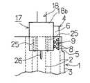
図1乃至図3は本発明に係るフラットケーブル用端子接続治具の最良の形態の一例を示したもので、図1は本例のフラットケーブル用端子接続治具の側面図、図2は図1の先端に設けられている挟み部の矢視図であって、この図の(A)は図1のA方向矢視図、この図の(B)は図1のB方向矢視図、図3は図2の(A)のC方向矢視図である。 1 to 3 show an example of the best mode of a flat cable terminal connection jig according to the present invention. FIG. 1 is a side view of the flat cable terminal connection jig of this example, and FIG. It is an arrow view of the pinch portion provided at the tip of 1, wherein (A) of this figure is a view in the direction of arrow A in FIG. 1, (B) of this figure is a view in the direction of arrow B in FIG. FIG. 3 is a view in the direction of the arrow C in FIG.
本例のフラットケーブル用端子接続治具17は、図1に示すように、1対の挟みアーム18,19を連結軸20でX形に開閉自在に連結して、連結軸20に対して一方側が1対の柄部18a,19a、他方側が1対の挟み部18b,19bとなっている挟み工具21を備えている。1対の挟み部18b,19bの一方の挟み部18bの内面には、図2の(A)及び図3に示すように、フラットケーブル接続端子4を各クリンプ片8が他方の挟み部19bの内面に対向する向きで仮留めする端子仮留め溝22が設けられ、1対の挟み部18b,19bの他方の挟み部19b内面にはフラットケーブル1を突き抜けた各クリンプ片8を折り曲げて加締めるクリンプ片曲成加締め凹部23と雌端子本体6を受ける端子本体受け凹部24とが設けられている。端子仮留め溝22の周壁部の内面には、図示しないがゴムの如きクッション材が貼り付けてあり、フラットケーブル接続端子4が容易に仮留めしたり、取り外したりすることができるようになっている。端子仮留め溝22の深さは、各クリンプ片8がフラットケーブル1を突き刺して加締めたとき、端子板部7がフラットケーブル1の表面から突き出す高さに設定され、1対の挟み部18b,19bがフラットケーブル1を挟んだ時にフラットケーブル接続端子4を必要以上に押圧しないようになっている。 As shown in FIG. 1, the flat cable
また、1対の挟み部18b,19bの一方の挟み部18bの内面には、図2の(A)(B)及び図3に示すように、フラットケーブル1のフラット導体2の幅方向の両側でフラット絶縁被覆3をトリミングする1対のトリミング突起25が突設され、1対の挟み部18b,19bの他方の挟み部19b内面には1対のトリミング突起25を受けるトリミング突起受け溝26が設けられている。トリミング突起25の突出高さh2 は、図3に示すように、挟み部18bの内面からのクリンプ片8の突出高さh1 より僅かに低く設定されている。 Further, as shown in FIGS. 2A and 2B and FIG. 3, both sides in the width direction of the
また、1対の挟み部18b,19bの一方の挟み部18bの先端の外面には、図2の(A)及び図3に示すように、フラットケーブル1のフラット導体2の幅方向の中間部が、両側のクリンプ片8の幅方向の中央になるようにフラットケーブル1を位置決めするための突起よりなるフラット導体位置決め目標部26が設けられている。 Further, as shown in FIG. 2A and FIG. 3, an intermediate portion in the width direction of the
また、1対の挟み部18b,19bの他方の挟み部19b内面には、図1乃至図3に示すように、フラットケーブル1の先端の先端の位置決めのための1対の突起よりなるケーブル先端位置決め部27が1対のトリミング突起25の内向き端部にほぼ対応して設けられている。1対の挟み部18b,19bの一方の挟み部18bの内面には、1対の突起よりなるケーブル先端位置決め部27を受ける受け孔28が設けられている。 Further, as shown in FIG. 1 to FIG. 3, on the inner surface of the
さらに、1対の挟み部18b,19bの幅方向の端部には、図2の(A)(B)及び図3に示すように、先にフラットケーブル1に接続されているフラットケーブル接続端子4を加圧しないように逃がす凹部よりなる端子逃がし部29が設けられている。 Further, at the end in the width direction of the pair of sandwiching
次に、このようなフラットケーブル用端子接続治具17によりフラットケーブル1にフラットケーブル接続端子4を接続する動作について、図1乃至図3と共に図4乃至図7を参照して説明する。図4は本例のフラットケーブル用端子接続治具でフラットケーブルに接続作業を行っている状態の平面図、図5は本例のフラットケーブル用端子接続治具でフラットケーブルを挟持する前の状態を示す横断面図、図6は本例のフラットケーブル用端子接続治具でフラットケーブルを挟持した状態を示す横断面図、図7はフラットケーブルにフラットケーブル接続端子を接続した状態の平面図である。 Next, the operation of connecting the flat
まず、図2の(A)及び図3に示すように、フラットケーブル用端子接続治具17の1対の挟み部18b,19bの一方の挟み部18bの内面の端子仮留め溝22にフラットケーブル接続端子4をその各クリンプ片8が他方の挟み部19bの内面に対向する向きで仮留めする。次に、1対の挟み部18b,19bの間にフラットケーブル1を、その先端が1対のケーブル先端位置決め部27に当たり、その接続すべきフラット導体2の幅方向の中央が両側のクリンプ片8の中央に位置するように、フラット導体位置決め目標部26をフラット導体2の幅方向の中央に位置させてフラットケーブル1を位置決めする。かかる状態で、1対の柄部18a,19aを作業者の手で締めることにより、1対の挟み部18b,19bを相互に接近する方向に移動して各クリンプ片8をフラット導体2の位置でフラットケーブル1に突き刺し、クリンプ片8とフラット導体2との導通を取り、フラットケーブル1を突き抜けた各クリンプ片8がクリンプ片曲成加締め凹部23で折り曲げて加締めることにより接続部9を形成する。 First, as shown in FIGS. 2A and 3, the flat cable is inserted into the terminal
また、1対の挟み部18b,19bを相互に接近する方向に移動する動作の時に、フラット導体2の幅方向の両側のフラット絶縁被覆3の部分が各トリミング突起25とトリミング突起受け溝26との噛み合わせで切り取られてトリミングスリット5がフラットケーブル1の先端に開口して形成される。 Further, during the operation of moving the pair of sandwiching
上記例では、トリミング突起25を挟み部18bに設け、ケーブル先端位置決め部27を挟み部19bに設けたが、その代わりにトリミング突起25を挟み部19bに設け、ケーブル先端位置決め部27を挟み部18bに設けてもよい。 In the above example, the trimming
また、ケーブル先端位置決め部27を1対の挟み部18b,19bの一方の内面に突設したが、これらケーブル先端位置決め部27は1対の挟み部18b,19bの一方の外側面に突設してもよい。このようにすると、1対の挟み部18b,19bの他方の内面に受け孔28を設ける必要がなくなる。 In addition, the cable
さらに、フラット導体位置決め目標部26は突起でなく、印刷等による標として設けてもよい。 Furthermore, the flat conductor
上記のように本例のフラットケーブル用端子接続治具17は、携帯型の安価な設備であり、電源のない所でもフラットケーブル接続端子4の接続を容易に行うことができる。 As described above, the flat cable
この場合、1対の挟み部18b,19bのいずれか一方の内面にはフラットケーブル1のフラット導体2の幅方向の両側でフラット絶縁被覆3をトリミングする1対のトリミング突起25が突設され、1対の挟み部18b,19bの他方の内面には1対のトリミング突起25を受けるトリミング突起受け溝26が設けられているので、1対の挟み部18b,19bでフラットケーブル1を挟む際にフラットケーブル1に対するトリミングスリット5の形成も一緒に行うことができる。 In this case, a pair of trimming
また、1対の挟み部18b,19bのいずれか一方の外面にはフラット導体2の幅方向の位置決めのためのフラット導体位置決め目標部26が設けられているので、このフラット導体位置決め目標部26を目標にフラット導体2が存在するようにフラットケーブル1の位置決めをすることにより、フラット導体2の位置決めを目視により容易に行うことができる。 Further, since the flat conductor
さらに、1対の挟み部18b,19bのいずれか一方にはフラットケーブル1の先端の先端の位置決めのためのケーブル先端位置決め部27が設けられているので、このケーブル先端位置決め部27にフラットケーブル1の先端を当てることにより、フラットケーブル1の先端の位置決めを容易に行うことができる。 Further, since either one of the pair of sandwiching
また、図6に示すように接続すべきフラット導体2の隣のフラット導体2にフラットケーブル接続端子4が先に接続されていても、挟み部18b,19bの幅方向の部分には端子逃がし部29が設けられているので、接続すべきフラット導体2の隣のフラット導体2に先にフラットケーブル接続端子4が接続されていても、このフラットケーブル接続端子4に後から加圧力を加えないで接続を行って、図7に示すような各フラット導体2の先端部にフラットケーブル接続端子4が接続されたフラットケーブル1を得ることができる。 Further, as shown in FIG. 6, even if the flat
上記例では、フラット導体2が複数条のフラットケーブル1の場合について説明したが、フラット導体2が1条のフラットケーブル1の場合には、トリミングスリット5の形成は必要ないので、フラットケーブル用端子接続治具17のトリミング突起25とトリミング突起受け溝26は省略することができる。 In the above example, the case where the
また上記例では、フラットケーブル1の端部のフラット導体2に、端子本体6を有するフラットケーブル接続端子4を接続する場合について示したが、図8で端子本体6がなく、端子板部7の幅方向の両側に複数のクリンプ片8を立設したフラットケーブル接続端子4を用いて、フラットケーブル1の相互の端部を突き合わせて、あるいは重ね合わせて、接続すべき相互のフラット導体2を端子板部7の各クリンプ片8で導通接続する用途、フラットケーブル1の長手方向の途中で分岐フラットケーブルを端子板部7の各クリンプ片8で導通接続する用途等にも、このフラットケーブル用端子接続治具17を使用することができる。これらの用途に使用する時には、ケーブル先端位置決め部27は不要である。このため、これらの場合には、ケーブル先端位置決め部27を備えていないフラットケーブル用端子接続治具17を用いたり、ケーブル先端位置決め部27を挟み部の孔から抜いて用いればよい。 In the above example, the case where the flat
本発明の請求項の他の請求項について、請求項1,2と共に、その目的、構成、効果について記載する。 Regarding other claims of the present invention, together with
本発明の目的は、携帯型の安価な設備で、電源のない所でもフラットケーブル接続端子の接続を容易に行えるフラットケーブル用端子接続治具を提供することにある。 An object of the present invention is to provide a flat cable terminal connecting jig which can be easily connected to a flat cable connecting terminal even in a place where there is no power source by a portable and inexpensive equipment.
本発明の他の目的は、フラットケーブルに対するトリミングスリットの形成も一緒に行えるフラットケーブル用端子接続治具を提供することにある。 Another object of the present invention is to provide a flat cable terminal connection jig that can also form a trimming slit for a flat cable.
本発明の他の目的は、フラット導体の位置決めを目視により容易に行えるフラットケーブル用端子接続治具を提供することにある。 Another object of the present invention is to provide a flat cable terminal connecting jig which can easily position a flat conductor visually.
本発明の他の目的は、フラットケーブルの先端の位置決めを容易に行えるフラットケーブル用端子接続治具を提供することにある。 Another object of the present invention is to provide a flat cable terminal connecting jig that can easily position the tip of the flat cable.
本発明の他の目的は、接続すべきフラット導体の隣のフラット導体に先にフラットケーブル接続端子が接続されていても、このフラットケーブル接続端子に後から加圧力を加えないで接続を行えるフラットケーブル用端子接続治具を提供することにある。 Another object of the present invention is to provide a flat cable that can be connected without applying pressure to the flat cable connection terminal later, even if the flat cable connection terminal is connected to the flat conductor next to the flat conductor to be connected. The object is to provide a cable terminal connection jig.
[請求項1]
フラット導体がフラット絶縁被覆で被覆されたフラットケーブルに、端子板部の幅方向の両側に複数のクリンプ片が立設されている構造のフラットケーブル接続端子の前記各クリンプ片を前記フラット導体の箇所で突き刺し、前記クリンプ片と前記フラット導体との導通を取り、前記フラットケーブルを突き抜けた前記各クリンプ片を折り曲げて加締めるフラットケーブル用端子接続治具において、
1対の挟みアームを連結軸でX形に開閉自在に連結して、前記連結軸に対して一方側が1対の柄部、他方側が1対の挟み部となっている挟み工具を備え、1対の前記挟み部の一方の内面には前記フラットケーブル接続端子を前記各クリンプ片が他方の前記挟み部の内面に対向する向きで仮留めする端子仮留め溝が設けられ、1対の前記挟み部の他方の内面には前記フラットケーブルを突き抜けた前記各クリンプ片を折り曲げて加締めるクリンプ片曲成加締め凹部が設けられていることを特徴とするフラットケーブル用端子接続治具。[Claim 1]
A flat cable in which a flat conductor is covered with a flat insulation coating, and a plurality of crimp pieces standing upright on both sides in the width direction of the terminal plate portion. In the flat cable terminal connection jig that stabs in, takes conduction between the crimp piece and the flat conductor, folds and crimps each crimp piece penetrating the flat cable,
A pair of sandwiching arms is connected to a connecting shaft so as to be openable and closable in an X shape, and includes a sandwiching tool having a pair of handle portions on one side and a pair of sandwiching portions on the other side. A terminal temporary fixing groove for temporarily fixing the flat cable connecting terminal in a direction in which each of the crimp pieces faces the inner surface of the other sandwiching portion is provided on one inner surface of the pair of sandwiching portions. The flat cable terminal connecting jig is characterized in that a crimp piece bending caulking recess for bending and crimping each crimp piece penetrating the flat cable is provided on the other inner surface of the portion.
[請求項2]
1対の前記挟み部のいずれか一方の内面には前記フラットケーブルの前記フラット導体の幅方向の両側で前記フラット絶縁被覆をトリミングする1対のトリミング突起が突設され、1対の前記挟み部の他方の内面には1対の前記トリミング突起を受けるトリミング突起受け溝が設けられていることを特徴とする請求項1に記載のフラットケーブル用端子接続治具。[Claim 2]
A pair of trimming projections for trimming the flat insulation coating is provided on the inner surface of one of the pair of sandwiching portions on both sides in the width direction of the flat conductor of the flat cable, and the pair of sandwiching portions. 2. The flat cable terminal connecting jig according to
[請求項3]
1対の前記挟み部のいずれか一方の外面には前記フラット導体の幅方向の位置決めのためのフラット導体位置決め目標部が設けられていることを特徴とする請求項1または2に記載のフラットケーブル用端子接続治具。[Claim 3]
3. The flat cable according to
[請求項4]
1対の前記挟み部のいずれか一方には前記フラットケーブルの先端の先端の位置決めのためのケーブル先端位置決め部が設けられていることを特徴とする請求項1〜3のいずれか1項に記載のフラットケーブル用端子接続治具。[Claim 4]
The cable tip positioning portion for positioning the tip of the tip of the flat cable is provided in any one of the pair of sandwiching portions. Flat cable terminal connection jig.
[請求項5]
1対の前記挟み部の幅方向の端部には端子逃がし部が設けられていることを特徴とする請求項1〜4のいずれか1項に記載のフラットケーブル用端子接続治具。[Claim 5]
The flat cable terminal connection jig according to any one of
次に、このような発明の効果について記載する。 Next, effects of such an invention will be described.
本発明に係るフラットケーブル用端子接続治具は、1対の挟みアームを連結軸でX形に開閉自在に連結して、連結軸に対して一方側が1対の柄部、他方側が1対の挟み部となっている挟み工具を備え、1対の挟み部の一方の内面にはフラットケーブル接続端子を各クリンプ片が他方の前記挟み部の内面に対向する向きで仮留めする端子仮留め溝が設けられ、1対の挟み部の他方の内面にはフラットケーブルを突き抜けた各クリンプ片を折り曲げて加締めるクリンプ片曲成加締め凹部が設けられた構造になっているので、携帯型の安価な設備であり、電源のない所でもフラットケーブル接続端子の接続を容易に行うことができる。 The flat cable terminal connecting jig according to the present invention connects a pair of sandwiching arms so as to be openable and closable in an X shape with a connecting shaft, and one side is a pair of handle portions and the other side is a pair of connecting shafts. A terminal temporary fixing groove provided with a pinching tool serving as a pinching portion, for temporarily fixing a flat cable connecting terminal on one inner surface of a pair of pinching portions in a direction in which each crimp piece faces the inner surface of the other pinching portion Is provided with a crimp piece bending caulking recess for bending and crimping each crimp piece penetrating the flat cable on the other inner surface of the pair of sandwiching portions. The flat cable connection terminal can be easily connected even in places where there is no power source.
この場合、1対の挟み部のいずれか一方の内面にはフラットケーブルのフラット導体の幅方向の両側でフラット絶縁被覆をトリミングする1対のトリミング突起が突設され、1対の挟み部の他方の内面には1対のトリミング突起を受けるトリミング突起受け溝が設けられていると、1対の挟み部でフラットケーブルを挟む際にフラットケーブルに対するトリミングスリットの形成も一緒に行うことができる。 In this case, a pair of trimming protrusions for trimming the flat insulation coating are provided on the inner surface of one of the pair of sandwiching portions on both sides in the width direction of the flat conductor of the flat cable, and the other of the pair of sandwiching portions When a pair of trimming projection receiving grooves for receiving a pair of trimming projections is provided on the inner surface, a trimming slit for the flat cable can be formed together when the flat cable is sandwiched between the pair of sandwiching portions.
また、1対の挟み部のいずれか一方の外面にはフラット導体の幅方向の位置決めのためのフラット導体位置決め目標部が設けられていると、このフラット導体位置決め目標部を目標にフラット導体が存在するようにフラットケーブルの位置決めをすることにより、フラット導体の位置決めを目視により容易に行うことができる。 Also, if a flat conductor positioning target part for positioning in the width direction of the flat conductor is provided on the outer surface of one of the pair of sandwiching parts, the flat conductor exists with this flat conductor positioning target part as a target. By positioning the flat cable in such a manner, the flat conductor can be easily positioned by visual observation.
また、1対の挟み部のいずれか一方にはフラットケーブルの先端の先端の位置決めのためのケーブル先端位置決め部が設けられていると、このケーブル先端位置決め部にフラットケーブルの先端を当てることにより、フラットケーブルの先端の位置決めを容易に行うことができる。 In addition, when a cable tip positioning portion for positioning the tip of the flat cable tip is provided in either one of the pair of sandwiching portions, by applying the tip of the flat cable to the cable tip positioning portion, The tip of the flat cable can be easily positioned.
さらに、1対の挟み部の幅方向の端部に端子逃がし部が設けられていると、接続すべきフラット導体の隣のフラット導体に先にフラットケーブル接続端子が接続されていても、このフラットケーブル接続端子に後から加圧力を加えないで接続を行うことができる。 Furthermore, if a terminal relief portion is provided at the end in the width direction of the pair of sandwiching portions, even if the flat cable connection terminal is connected to the flat conductor adjacent to the flat conductor to be connected first, Connection can be made without applying pressure to the cable connection terminal later.
1 フラットケーブル
2 フラット導体
3 フラット絶縁被覆
4 フラットケーブル接続端子
5 トリミングスリット
6 雌端子本体
7 端子板部
8 クリンプ片
9 接続部
10 フラットケーブル用端子接続装置
11 ケーブル支え台
12 クリンプ片受け溝
13 仕切り板
14 クリンプ片曲成加締め凹部
15 アンビル
16 ガイド部材
17 フラットケーブル用端子接続治具
18,19 挟みアーム
18a,19a 柄部
18b,19b 挟み部
20 連結軸
21 挟み工具
22 端子仮留め溝
23 クリンプ片曲成加締め凹部
24 端子本体受け凹部
25 トリミング突起
26 トリミング突起受け溝
27 ケーブル先端位置決め部
28 受け孔
29 端子逃がし部DESCRIPTION OF
Claims (2)
Translated fromJapanese1対の挟みアームを連結軸で開閉自在に連結して、前記連結軸に対して一方側が1対の柄部、他方側が1対の挟み部となっている挟み工具を備え、1対の前記挟み部の一方の内面には前記フラットケーブル接続端子を前記各クリンプ片が他方の前記挟み部の内面に対向する向きで仮留めする端子仮留め溝が設けられ、1対の前記挟み部の他方の内面には前記フラットケーブルを突き抜けた前記各クリンプ片を折り曲げて加締めるクリンプ片曲成加締め凹部が設けられていることを特徴とするフラットケーブル用端子接続治具。A flat cable in which a flat conductor is covered with a flat insulation coating, and a plurality of crimp pieces standing upright on both sides in the width direction of the terminal plate portion. In the flat cable terminal connection jig that stabs in, takes conduction between the crimp piece and the flat conductor, folds and crimps each crimp piece penetrating the flat cable,
A pair of sandwiching arms are connected to each other by a connecting shaft so as to be freely opened and closed, and a pair of gripping tools each having a pair of handle portions on one side and a pair of sandwiching portions on the other side with respect to the connecting shaft are provided. A terminal temporary fixing groove for temporarily fixing the flat cable connecting terminal in a direction in which each of the crimp pieces faces the inner surface of the other holding portion is provided on one inner surface of the holding portion, and the other of the pair of the holding portions. The flat cable terminal connecting jig is characterized in that a crimp piece bending caulking recess for bending and crimping each crimp piece penetrating the flat cable is provided on the inner surface of the flat cable.
Priority Applications (1)
| Application Number | Priority Date | Filing Date | Title |
|---|---|---|---|
| JP2003282467AJP2005050718A (en) | 2003-07-30 | 2003-07-30 | Flat cable terminal connection jig |
Applications Claiming Priority (1)
| Application Number | Priority Date | Filing Date | Title |
|---|---|---|---|
| JP2003282467AJP2005050718A (en) | 2003-07-30 | 2003-07-30 | Flat cable terminal connection jig |
Publications (1)
| Publication Number | Publication Date |
|---|---|
| JP2005050718Atrue JP2005050718A (en) | 2005-02-24 |
Family
ID=34267672
Family Applications (1)
| Application Number | Title | Priority Date | Filing Date |
|---|---|---|---|
| JP2003282467APendingJP2005050718A (en) | 2003-07-30 | 2003-07-30 | Flat cable terminal connection jig |
Country Status (1)
| Country | Link |
|---|---|
| JP (1) | JP2005050718A (en) |
Cited By (5)
| Publication number | Priority date | Publication date | Assignee | Title |
|---|---|---|---|---|
| WO2014200073A1 (en)* | 2013-06-14 | 2014-12-18 | 矢崎総業株式会社 | Flat-cable connection structure |
| WO2014200074A1 (en)* | 2013-06-14 | 2014-12-18 | 矢崎総業株式会社 | Flat-cable connection structure |
| WO2015030232A1 (en)* | 2013-09-02 | 2015-03-05 | 矢崎総業株式会社 | Terminal-equipped flat cable |
| US9678437B2 (en) | 2003-04-09 | 2017-06-13 | Nikon Corporation | Illumination optical apparatus having distribution changing member to change light amount and polarization member to set polarization in circumference direction |
| US9885872B2 (en) | 2003-11-20 | 2018-02-06 | Nikon Corporation | Illumination optical apparatus, exposure apparatus, and exposure method with optical integrator and polarization member that changes polarization state of light |
- 2003
- 2003-07-30JPJP2003282467Apatent/JP2005050718A/enactivePending
Cited By (10)
| Publication number | Priority date | Publication date | Assignee | Title |
|---|---|---|---|---|
| US9678437B2 (en) | 2003-04-09 | 2017-06-13 | Nikon Corporation | Illumination optical apparatus having distribution changing member to change light amount and polarization member to set polarization in circumference direction |
| US9885959B2 (en) | 2003-04-09 | 2018-02-06 | Nikon Corporation | Illumination optical apparatus having deflecting member, lens, polarization member to set polarization in circumference direction, and optical integrator |
| US9885872B2 (en) | 2003-11-20 | 2018-02-06 | Nikon Corporation | Illumination optical apparatus, exposure apparatus, and exposure method with optical integrator and polarization member that changes polarization state of light |
| US10281632B2 (en) | 2003-11-20 | 2019-05-07 | Nikon Corporation | Illumination optical apparatus, exposure apparatus, and exposure method with optical member with optical rotatory power to rotate linear polarization direction |
| WO2014200073A1 (en)* | 2013-06-14 | 2014-12-18 | 矢崎総業株式会社 | Flat-cable connection structure |
| WO2014200074A1 (en)* | 2013-06-14 | 2014-12-18 | 矢崎総業株式会社 | Flat-cable connection structure |
| JP2015002051A (en)* | 2013-06-14 | 2015-01-05 | 矢崎総業株式会社 | Connection structure of flat cable |
| US9472863B2 (en) | 2013-06-14 | 2016-10-18 | Yazaki Corporation | Flat-cable connection structure |
| WO2015030232A1 (en)* | 2013-09-02 | 2015-03-05 | 矢崎総業株式会社 | Terminal-equipped flat cable |
| JP2015050029A (en)* | 2013-09-02 | 2015-03-16 | 矢崎総業株式会社 | Flat cable with terminal |
Similar Documents
| Publication | Publication Date | Title |
|---|---|---|
| JP3910874B2 (en) | Flat cable connector and flat cable connector | |
| JP2005050718A (en) | Flat cable terminal connection jig | |
| JP3683769B2 (en) | Mounting structure and mounting method of branch connector to flat circuit body | |
| US3835241A (en) | Adaptor for modifying connector to accommodate smaller conductors | |
| US20230411871A1 (en) | Compression connectors and protective covers | |
| US7413465B2 (en) | Insulation displacement system | |
| EP0057579A2 (en) | Electric connectors | |
| US4725247A (en) | Cable splicing assembly | |
| JPH0824063B2 (en) | Cable terminal processing apparatus and cable terminal processing method | |
| EP0084257B1 (en) | Termination and terminal for ribbon conductors | |
| JP3454729B2 (en) | Electrical connection terminal and electrical connector | |
| JP3833944B2 (en) | Connection method and connection device between flat cable and connection terminal | |
| US20060246767A1 (en) | Wire-terminal element | |
| JP3735044B2 (en) | Connection method between flat conductor of flat cable and electrical connection terminal | |
| WO2020150524A1 (en) | Compression connectors with insulating cover | |
| US3614294A (en) | Device for rapidly interconnecting two insulated electrical conductors | |
| JP2001185247A (en) | Crimp joint connector | |
| JPH076624Y2 (en) | Crimp connector | |
| JP4493574B2 (en) | Connecting terminal | |
| JP3665604B2 (en) | Method for mounting electronic components on a wiring circuit body | |
| JP4234336B2 (en) | Connection method and connection device between flat cable and connection terminal | |
| JP2004311268A (en) | Connection method and connection device for flat cable and connection fitting | |
| JP4494707B2 (en) | Connection method and connection structure of flat cable and flat cable connector | |
| JPH0587824U (en) | Connector | |
| JP2623142B2 (en) | Jig for flat cable |