JP2005045724A - Inquiry response device - Google Patents
Inquiry response deviceDownload PDFInfo
- Publication number
- JP2005045724A JP2005045724AJP2003280157AJP2003280157AJP2005045724AJP 2005045724 AJP2005045724 AJP 2005045724AJP 2003280157 AJP2003280157 AJP 2003280157AJP 2003280157 AJP2003280157 AJP 2003280157AJP 2005045724 AJP2005045724 AJP 2005045724A
- Authority
- JP
- Japan
- Prior art keywords
- caller
- user
- database
- receiver
- message
- Prior art date
- Legal status (The legal status is an assumption and is not a legal conclusion. Google has not performed a legal analysis and makes no representation as to the accuracy of the status listed.)
- Pending
Links
Images


Landscapes
- Mobile Radio Communication Systems (AREA)
- Telephone Function (AREA)
Abstract
Translated fromJapaneseDescription
Translated fromJapanese本発明は、居住空間内に備え付けられた受信装置に付属し、受信者に代わって発信者に応答可能な問い合わせ応答装置に関する。 The present invention relates to an inquiry response device that is attached to a receiving device provided in a living space and can respond to a caller on behalf of a receiver.
発信者からの問い合わせに応じる受信装置やシステムとして、居住空間内で利用されているものには、例えば、電話機、居住空間への直接の訪問時に利用されるインターホン、インターネットを介したEメールやネットミーティングなどがある。その中で、特に電話機に関しては、受信者が応答できないときに受信者の代わりに応答するいわゆる留守番機能が、すでに広範に普及している。 Examples of receiving devices and systems that respond to inquiries from callers are those used in living spaces, such as telephones, intercoms used during direct visits to living spaces, e-mails and networks via the Internet. There are meetings. Among them, particularly with respect to telephones, a so-called answering machine function that responds on behalf of a receiver when the receiver cannot respond has already become widespread.
通常の留守番機能付き電話機は、利用者が、外出等の際には事前に留守番電話機能を起動しておき、帰宅等の際には留守番電話機能を解除する必要がある。また、着信音が鳴り続けても受信者が電話に応答しないときには、発信者に対して受信者が不在である旨を告げ、発信者のメッセージや着信日時をテープ等の記憶メディアに記録することができる。 In a normal telephone with an answering machine function, it is necessary for the user to activate the answering machine function in advance when going out and to cancel the answering machine function when returning home. If the recipient does not answer the phone even if the ringing tone continues to sound, inform the caller that the recipient is absent and record the caller's message and the date and time of the call on a storage medium such as tape. Can do.
特許文献1では、使用者のスケジュールテーブルを事前に準備し、スケジュールの有無に応じて、留守番電話機能を自動で起動・解除する技術が開示されている。また、留守番メッセージデータを蓄積して、各スケジュールに応じた留守番メッセージを発信者に伝える技術も示されている。
特許文献2では、使用者のスケジュールテーブルと各スケジュールに対応した留守番メッセージデータを事前に準備し、受信者のスケジュールを発信者に対して自動的に伝える技術が開示されている。これにより、他人を介することなく、発信者が受信者の行動を確実に把握することができる。また、発信者にランク付けをなし、発信先の電話番号から発信者を識別して、そのランクに応じたメッセージやスケジュールの詳細を伝える技術も示されている。
特許文献3では、留守番電話近辺における人の有無を検出するセンサと、在宅か不在かを設定するスイッチと、発信者への複数種類の応答メッセージとを備えた構成が開示されている。この構成により、たとえ在宅のスイッチが入っていても、電話機近辺に人が検出できないときは、適切な応答メッセージを選択して発信者に伝えることができる。
しかしながら、特許文献1,2では、毎日のスケジュールテーブルを利用者自らが作成しなければならない。またスケジュールに変更があった場合は、それに合わせてスケジュールテーブルを変更しなければならず、同様に留守番メッセージデータもスケジュールに合わせて変更しなければならない。このようなスケジュールや留守番メッセージの変更作業を怠った場合は、発信者に対して誤った情報を伝えてしまうおそれがある。また、入浴中、手洗い中、就寝中といった細かなスケジュールを予め設定しておくことは、煩雑であり、現実にはきわめて困難である。 However, in
また、特許文献1,2では、一個人が利用する装置を前提としている。ところが、複数の利用者が共通の装置を利用する場合、スケジュール、メッセージおよびランク付けは、当然、各利用者によって異なるものとなる。この点については、特許文献1,2では何ら示されていない。 In
また、特許文献3では、受信者が在宅か不在か、電話機近傍に人がいるかいないか、という4種類の状況にしか対応できず、受信者の状況を発信者に適切に伝えるには限界がある。さらに、例えば受信者が電話機とは異なる部屋にいる場合、受信者は応答可能であるにもかかわらず、センサによって人が検出されないので、発信者に留守番メッセージが送信されてしまう。 In
上述した問題は、電話機の留守番機能に限られるものではなく、例えば、インターホン、インターネットを介したEメールやネットミーティングなど、発信者からの問い合わせに応じる他の受信装置やシステムに、受信者に代わって発信者に応答する機能を付す場合にも、同様の問題が生じる。 The above-mentioned problems are not limited to the answering machine function of the telephone. For example, interphones, other e-mails via the Internet, net meetings, and other receiving devices and systems that respond to inquiries from callers can be used on behalf of the receiver. The same problem occurs when a function for responding to the caller is added.
前記の問題に鑑み、本発明は、居住空間内の受信装置に付属する問い合わせ応答装置として、利用者に煩雑な作業を強いることなく、着信に対して的確に応答可能にすることを課題とする。また、複数の使用者がいる場合でも、着信に対して的確に応答可能にすることを課題とする。 In view of the above problems, an object of the present invention is to make it possible to accurately respond to an incoming call without forcing the user to perform complicated operations as an inquiry response device attached to a receiving device in a living space. . It is another object of the present invention to make it possible to accurately respond to incoming calls even when there are a plurality of users.
前記の課題を解決するために、第1の発明は、居住空間内の受信装置に付属する問い合わせ応答装置として、受信装置の使用者について居場所および行動を管理する使用者行動データベースを用いて、着信があったとき、発信先の個別情報から発信者を識別して受信者を特定し、使用者行動データベースを参照して、特定した受信者が着信に応答可能か否かを判断するものである。 In order to solve the above-mentioned problem, the first invention uses a user behavior database that manages the location and behavior of a user of a receiving device as an inquiry response device attached to the receiving device in a living space. When there is a call, the caller is identified from the individual information of the callee, the receiver is specified, and the user behavior database is referred to determine whether the specified receiver can respond to the incoming call. .
この発明によると、受信装置の使用者について、その居場所や行動が使用者行動データベースに管理されているため、特定された受信者が着信に応答可能か否かを、使用者行動データベースを参照することによって精度良く判断できる。このため、利用者は、自分のスケジュールの登録や更新を行う必要がなく、着信に応答できないときは、例えば問い合わせ装置から発信者に対して自動的にメッセージを送信することができる。したがって、利用者の手を煩わせることなく、いつでも的確に着信に応答することができる。 According to the present invention, since the whereabouts and actions of the user of the receiving device are managed in the user action database, the user action database is referred to whether or not the specified receiver can respond to the incoming call. Can be determined with high accuracy. For this reason, the user does not need to register or update his / her schedule, and when the user cannot respond to an incoming call, for example, a message can be automatically transmitted from the inquiry device to the caller. Therefore, it is possible to accurately answer an incoming call at any time without bothering the user.
また、第2の発明は、居住空間内の受信装置に付属する問い合わせ応答装置として、発信先の候補となる発信候補者について、その個別情報と、受信装置の各使用者との関係とを管理する発信者データベースを用いて、着信があったとき、発信者データベースを参照して、発信先の個別情報から発信者を識別し、各使用者の中から受信者を特定するものである。 Moreover, 2nd invention manages the individual information and the relationship with each user of a receiving apparatus about the transmission candidate who becomes a candidate of a transmission destination as an inquiry response apparatus attached to the receiving apparatus in living space. The incoming caller database is used to refer to the outgoing caller database, identify the outgoing caller from the individual information of the outgoing call destination, and specify the recipient from each user.
この発明によると、発信候補者について、その個別情報と、受信装置の各使用者との関係が発信者データベースに管理されているため、着信があったとき、発信先の個別情報から、発信者データベースを参照して、発信者を識別できるとともに、各使用者の中から受信者を特定することができる。すなわち、複数の使用者がいる場合でも、発信先の個別情報から受信者が特定できるので、発信者に対して的確なメッセージを選択送信したり、受信者個別の着信音を鳴らしたりすることができる。 According to the present invention, since the relationship between the individual information and each user of the receiving device is managed in the sender database for the transmission candidate, when there is an incoming call, from the individual information of the destination, the sender By referring to the database, the sender can be identified, and the receiver can be specified from among the users. In other words, even when there are multiple users, the receiver can be identified from the individual information of the destination, so that an accurate message can be selectively transmitted to the sender, or a ring tone for each receiver can be sounded. it can.
本発明によると、利用者がスケジュールの登録や更新といった煩雑な作業を行わなくても、着信に対していつでも的確に応答することができる。また、複数の使用者がいる場合でも、着信に的確に応答することができる。 According to the present invention, even if the user does not perform complicated work such as registration and update of a schedule, it is possible to respond accurately to an incoming call at any time. Further, even when there are a plurality of users, it is possible to accurately answer incoming calls.
本発明の第1態様によれば、居住空間内の受信装置に付属する問い合わせ応答装置として、前記受信装置の使用者について、少なくとも、居場所および行動を管理する使用者行動データベースと、制御部とを備え、前記制御部は、前記受信装置に着信があったとき、発信先の個別情報から発信者を識別し、識別した発信者から受信者を特定し、前記使用者行動データベースを参照して、特定した受信者が前記着信に応答可能か否かを判断するものを提供する。 According to the first aspect of the present invention, as an inquiry response device attached to a receiving device in a living space, for a user of the receiving device, at least a user behavior database for managing a whereabouts and behavior, and a control unit The control unit, when there is an incoming call to the receiving device, identifies the caller from the individual information of the destination, identifies the receiver from the identified caller, referring to the user behavior database, What determines whether the specified receiver can respond to the said incoming call is provided.
本発明の第2態様によれば、前記受信装置は電話機であり、前記個別情報は電話番号である第1態様の問い合わせ応答装置を提供する。 According to a second aspect of the present invention, there is provided the inquiry response device according to the first aspect, wherein the receiving device is a telephone and the individual information is a telephone number.
本発明の第3態様によれば、前記制御部は、前記受信者が応答可能と判断したとき、前記使用者行動データベースを参照して、前記受信者の居場所および行動に応じて、着信音の種類および音量のうち少なくとも1つを設定する第1態様の問い合わせ応答装置を提供する。 According to the third aspect of the present invention, when the control unit determines that the receiver can respond, the control unit refers to the user behavior database and determines the ringtone according to the location and behavior of the receiver. A query response device according to a first aspect for setting at least one of a type and a volume is provided.
本発明の第4態様によれば、前記使用者について、少なくとも、その行動に応じた緊急時の対応を管理する緊急設定データベースを備え、前記制御部は、前記受信者が応答不能と判断したとき、前記着信が緊急か否かを判断し、緊急と判断したとき、前記緊急設定データベースを参照して前記受信者の行動に応じた緊急時対応をとる第1態様の問い合わせ応答装置を提供する。 According to the fourth aspect of the present invention, the user is provided with an emergency setting database that manages at least an emergency response according to the action, and the control unit determines that the receiver cannot respond. A first aspect of the inquiry response device for determining whether or not the incoming call is urgent and taking an emergency response according to the behavior of the recipient with reference to the emergency setting database when the emergency is determined to be emergency is provided.
本発明の第5態様によれば、前記制御部は、前記受信者が応答不能と判断したとき、前記発信者にメッセージを送信し、送信したメッセージに対する前記発信者の応答に基づいて、前記着信が緊急か否かの判断を行う第4態様の問い合わせ応答装置を提供する。 According to a fifth aspect of the present invention, the control unit transmits a message to the caller when the receiver determines that the response is impossible, and receives the incoming call based on the caller's response to the transmitted message. An inquiry response device according to a fourth aspect for determining whether or not is an emergency is provided.
本発明の第6態様によれば、緊急であることを示す緊急語を記憶する緊急語データベースを備え、前記制御部は、発信された情報がメールであるとき、前記着信が緊急か否かの判断を、前記緊急語データベースを参照して、前記メールが緊急語を含むか否かに応じて行う第4態様の問い合わせ応答装置を提供する。 According to a sixth aspect of the present invention, there is provided an emergency word database for storing an emergency word indicating emergency, and the control unit determines whether the incoming call is emergency when the transmitted information is an email. A query response device according to a fourth aspect is provided in which a determination is made by referring to the emergency word database depending on whether or not the mail includes an emergency word.
本発明の第7態様によれば、居住空間内の受信装置に付属する問い合わせ応答装置として、発信先の候補となる発信候補者について、少なくとも、その個別情報と、前記受信装置の各使用者との関係とを管理する発信者データベースと、制御部とを備え、前記制御部は、前記受信装置に着信があったとき、前記発信者データベースを参照して、発信先の個別情報から発信者を識別し、識別した発信者から、前記発信者データベースを参照して、前記各使用者の中から受信者を特定する問い合わせ応答装置を提供する。 According to the seventh aspect of the present invention, as the inquiry response device attached to the receiving device in the living space, at least the individual information and each user of the receiving device with respect to the sending candidate who is a candidate for the destination A caller database that manages the relationship between the caller and the control unit, and when the receiving device receives an incoming call, the control unit refers to the caller database and determines the caller from the individual information of the callee An inquiry response device is provided that identifies and identifies a recipient from among the users by referring to the sender database from the identified sender.
本発明の第8態様によれば、前記受信装置は電話機であり、前記個別情報は電話番号である第7態様の問い合わせ応答装置を提供する。 According to an eighth aspect of the present invention, there is provided the inquiry response device according to the seventh aspect, wherein the receiving device is a telephone and the individual information is a telephone number.
本発明の第9態様によれば、前記発信者データベースは、発信候補者と各使用者との間の親密度を管理する第7態様の問い合わせ応答装置を提供する。 According to a ninth aspect of the present invention, the sender database provides the inquiry response device according to the seventh aspect, which manages the closeness between the transmission candidate and each user.
本発明の第10態様によれば、前記制御部は、特定した受信者が応答可能か否かを判断し、前記受信者が応答不能と判断したとき、前記発信者データベースに管理された発信者と当該受信者との間の親密度に応じて、動作を決定する第9態様の問い合わせ応答装置を提供する。 According to the tenth aspect of the present invention, the control unit determines whether or not the identified receiver can respond, and when the receiver determines that the response is impossible, the sender managed in the sender database The inquiry response device according to the ninth aspect for determining the operation according to the closeness between the receiver and the receiver.
本発明の第11態様によれば、前記制御部は、特定した受信者が応答可能か否かを判断し、前記受信者が応答不能と判断したとき、前記発信者データベースを参照して、次に親密度の高い使用者を新たな受信者として特定する第9態様の問い合わせ応答装置を提供する。 According to an eleventh aspect of the present invention, the control unit determines whether or not the identified receiver is capable of responding, and when the receiver determines that the response is impossible, refers to the sender database and An inquiry response device according to a ninth aspect is provided that identifies a user with a high degree of closeness as a new recipient.
以下、本発明の実施の形態について、図面を参照しながら説明する。 Hereinafter, embodiments of the present invention will be described with reference to the drawings.
(第1の実施形態)
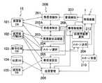
図1は本発明の第1の実施形態に係る問い合わせ応答装置の全体構成を示すブロック図である。図1の問い合わせ応答装置は、家庭のような居住空間内に置かれた例えば固定電話機のような受信装置1に付属するものであり、大きく、データ格納部10と、制御部20とを備えている。(First embodiment)
FIG. 1 is a block diagram showing the overall configuration of an inquiry response device according to the first embodiment of the present invention. The inquiry response device in FIG. 1 is attached to the
データ格納部10は 発信者となり得る人の情報を管理するための発信者データベース(以下、「DB」と略記する)101と、受信装置1の使用者の行動を管理するための使用者行動DB102と、留守時など受信者が応答不能のときに送信する留守番メッセージを記憶するための留守応答DB103と、発信者からの伝言メッセージを記憶するための伝言DB104と、受信装置1の使用者の情報を管理するための使用者DB105とを備えている。使用者行動DB102は、詳しくは後述するが、居住空間内に設置されたセンサ2の出力を基にして、使用者行動検出部33によって常時更新される。また、発信者DB101、留守応答DB103および使用者DB105のデータは、装置外部から、データ入力部31およびデータ登録部32を介して更新可能である。 The
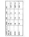
図2は発信者DB101に格納された情報の例である。図2の発信者DB101では、発信先の候補となる発信候補者F,G,H,Iさんについて、電話番号などの個別情報と、受信装置1の各使用者A,B,Cさんとの関係とが、それぞれ管理されている。さらに、発信候補者と各使用者との間の親密度も管理されている。親密度はここでは、3段階評価で管理されている。図2から例えば、GさんはAさんの上司にあたるが、その親密度は「3(疎遠)」であることが分かる。 FIG. 2 is an example of information stored in the
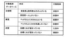
図3は使用者行動DB102に格納された情報の例である。図3の使用者行動DB102では、受信装置1の使用者A,B,C,D,Eさんについて、現在の居場所、行動、および着信に応答できるか否かが、それぞれ管理されている。図3から例えば、Aさんは応接間にいるが、来客の対応をしており、応答はできないことが分かる。 FIG. 3 is an example of information stored in the
留守応答DB103には、受信者が着信に応答できないときに本装置が受信者の代わりに発信者に対して送るメッセージが記録されている。伝言DB104には、着信があったとき、その着信日時、発信者名、発信者からの伝言メッセージ、および、発信者と関係のある使用者が記録される。 The answering
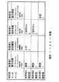
図4は使用者DB105に格納された情報の例である。図4の使用者DB105では、各使用者について、着信音の種類が記憶されている。また、居住空間における各使用者の行動を検出するために、各使用者の外見上の特徴を表すデータが格納されている。 FIG. 4 is an example of information stored in the
一方、図1にもどり、制御部20は、発信者識別部201、受信者特定部202、受信者状況確認部203、メッセージ選択部204、着信音設定部205および伝言管理部206を備えている。制御部20はさらに、受信装置1に着信があったことを検知する着信検知部207、受信装置1の着信音を起動する着信音起動部208、メッセージ送信部209およびメッセージ受信部210を備えている。 On the other hand, returning to FIG. 1, the
発信者識別部201は、着信検知部207によって着信が検知されたとき、発信先の個別情報としての電話番号やIPアドレス等を調べる。そして、その個別情報を基に、発信者DB101を参照して、発信者が誰であるかを識別する。 When the incoming
受信者特定部202は、発信者識別部201によって識別された発信者から、受信者を特定する。このとき、発信者DB101に格納された発信候補者と使用者との関係を参照する。受信者状況確認部203は、受信者特定部202によって特定された受信者について、使用者行動DB102を参照して現在の状況を確認し、受信者特定部202に報告する。 The
受信者特定部202は、受信者が着信に応答可能であるときは、着信音設定部205に着信音の種類を設定するよう指示し、着信音起動部208に着信音を起動するよう指示する。着信音設定部205は、使用者DB105に規定された各使用者毎の着信音種類を参照する。これにより、受信者特有の着信音が鳴るので、使用者は自分固有の着信音が鳴ったときだけ着信に応答すればよい。一方、受信者が着信に応答不能であるときは、受信者特定部202は、メッセージ選択部204に留守番メッセージを選択するよう指示する。メッセ−ジ選択部204は、適切なメッセージを留守応答DB103から選び出す。このとき、必要に応じて、発信者DB101に格納された発信者と受信者との関係や、使用者行動DB102に格納された受信者の現在の状況を参照する。メッセージ選択部204によって選択された留守番メッセージは、メッセージ送信部209によって受信装置1に送信される。 When the receiver can respond to an incoming call, the
メッセージ受信部210は、受信装置1から発信者の伝言メッセージを受信する。伝言管理部206は、メッセージ受信部210によって受信された伝言メッセージを伝言DB104に格納する。伝言管理部206はまた、使用者行動DB102を参照して、着信に応答できなかった受信者が応答可能な状況になったことを検知すると、着信音起動部208によって着信音を起動するとともに、伝言DB104からその受信者宛に届いている伝言メッセージを読み出す。読み出された伝言メッセージはメッセージ送信部209によって送信される。 The
データ入力部31は、当該問い合わせ応答装置の外部から与えられたデータを入力するものであり、押しボタン、タッチパネルなどによって構成される。入力されるデータは、留守番メッセージ、使用者固有の着信音設定、使用者と発信者との関係データなどであり、これらのデータは、データ登録部32によって各DBに記録される。 The
行動推測DB34には、使用者の状況を推測するための各条件データが記録されている。使用者行動検出部33は、居住空間内に設置されたセンサ2の出力を基にして、使用者DB105および行動推測DB34を参照して、使用者行動DB102を常時更新する。 Each condition data for estimating the user's situation is recorded in the
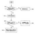
図5は図1の問い合わせ装置の動作の一例を示すフローチャートである。図5を参照して、図1の問い合わせ装置の動作について説明する。 FIG. 5 is a flowchart showing an example of the operation of the inquiry device of FIG. The operation of the inquiry device in FIG. 1 will be described with reference to FIG.
まず、着信がくるのを待っている状態(S11)では、使用者行動検出部33が、受信装置1の各使用者について現在の居場所と行動を把握し、使用者行動DB102を常時更新している。そして、いまだ着信がない状態において(S12でNo)、着信が入ると(S13)、発信者識別部201は発信先の電話番号を検出し、発信者DB101を参照して、検出した電話番号から発信者を識別する。ここでは、検出した電話番号が「03asdfghkl」であったとし、図2の発信者DB101を参照することによって、発信者が上司Gであると識別される(S14)。 First, in a state of waiting for an incoming call (S11), the user
次に、受信者特定部202が、発信者識別部201によって識別された発信者から、発信者DB101に管理された発信候補者と各使用者との関係を基にして、受信者を特定する(S15)。識別された発信者と関係がある使用者が複数いる場合は、親密度がより高い使用者を受信者として特定する。ここでは図2から、使用者Aが受信者として特定される(S16でYes)。 Next, the
次に、受信者状況確認部203が、受信者特定部202によって特定された受信者すなわち使用者Aについて、使用者行動DB102を参照して、その行動や状況を確認する(S17)。ここでは、図3から、使用者Aは、在宅しており応接間にいるが、来客中で忙しく、着信には応答できないことが分かる(S18でNo)。使用者Aが応答できないので、受信者特定部202は再び発信者DB101を参照し、次に親密度が高い使用者を新たな受信者として特定する。ここでは、他に受信者となり得る使用者がいないので(S21でNo)、ステップS22にすすむ。 Next, the receiver
ステップS22において、メッセージ選択部204が、留守応答DB103から最適な留守番メッセージを選択する。このときメッセージ選択部204は、発信者DB101に管理された発信者と受信者との関係を参照する。図2から、発信者Gは受信者Aの上司に当たり、親密度は「3」と低い。このため、留守番メッセージとしては、例えば「ただいま電話に出ることができません」といった簡単なものを選択する。なお、発信者と受信者との親密度が高い場合は、受信者の現在の状況や着信に応答できない理由の詳細等を、例えば使用者行動DB102を参照して、留守番メッセージに付加するようにしてもよい。そして、メッセージ送信部209が、メッセージ選択部204によって選択されたメッセージを受信装置1に送信する(S23)。留守番メッセージに対して、発信者からのメッセージが受信装置1に送信されると、メッセージ受信部210はそのメッセージを受信し、伝言管理部206が伝言DB104に録音する。その後、使用者Aに対して着信が一件ある状態で、ステップS11に戻る。 In step S <b> 22, the
この状況において、使用者Aの来客が帰ったとすると、使用者Aは着信に応答可能な状態になる(S12でYes)。このとき、伝言管理部206は、使用者行動DB102を参照して使用者Aが応答可能になったことを検知すると、着信音設定部205に着信音の設定を指示するとともに、着信音起動部208に着信音の起動を指示する(S25)。着信音設定部205は、使用者DB105を参照して着信音を設定する。ここでは図4から、「2番」の着信音が起動される。 In this situation, if the visitor of the user A returns, the user A can respond to the incoming call (Yes in S12). At this time, when the
使用者Aが着信音に気づき、着信を確認するとき、伝言DB104に発信者からの伝言メッセージが録音されているときは(S26でYes)、伝言管理部206はメッセージ送信部209を介してそのメッセージを再生する(S28)。一方、伝言DB104に伝言メッセージが録音されていないときは(S26でNo)、伝言管理部206は、何時何分にEさんから着信がありましたというメッセージを、メッセージ送信部209を介して再生する(S27)。その後、ステップS11に戻る。 When the user A notices the ring tone and confirms the incoming call, or when the message message from the caller is recorded in the message DB 104 (Yes in S26), the
また、着信があって、特定した受信者が応答可能であるときは(S18でYes)、受信者特定部202は、着信音設定部205に着信音の設定を指示するとともに、着信音起動部208に着信音の起動を指示する。受信者が応答し(S20)、応答が終了すると、ステップS11に戻る。 When there is an incoming call and the identified receiver can respond (Yes in S18), the
以上のように本実施形態によると、まず、受信装置1の使用者について、その居場所や行動が使用者行動DB102に管理されているため、受信者特定部202によって特定された受信者が着信に応答可能か否かを、受信者状況確認部203が使用者行動DB102を参照することによって精度良く判断できる。このため、自分のスケジュールの登録や更新を行わなくて、受信者が着信に応答できないときは、問い合わせ装置から発信者に対して自動的にメッセージが送信される。したがって、利用者の手を煩わせることなく、いつでも的確に着信に応答することができる。 As described above, according to the present embodiment, since the whereabouts and actions of the user of the receiving
また、発信候補者について、その個別情報と、受信装置の各使用者との関係が発信者DB101に管理されているため、着信があったとき、発信者識別部201および受信者特定部202によって、発信先の個別情報から、発信者DB101を参照して、発信者の識別と受信者の特定を実行できる。すなわち、複数の使用者がいる場合でも、発信先の個別情報から受信者が特定できるので、発信者に対して的確なメッセージを選択送信したり、受信者個別の着信音を鳴らしたりすることができる。 Moreover, since the relationship between the individual information and each user of the receiving device is managed in the
なお、電話番号非通知など発信者が識別できない場合には、受信者を特定することもできない。このような場合は、例えば、使用者行動DB102を参照して、着信に応答可能な使用者が1人でもいるときは、着信音を起動し、使用者全員が応答不能であるときは、発信者に対して留守番メッセージを送信し、発信者の伝言メッセージを記録するようにすればよい。 If the caller cannot be identified, such as when the telephone number is not notified, the recipient cannot be specified. In such a case, for example, referring to the
また、各部屋に電話機等の受信装置が設置されている場合は、着信があったとき、受信者がいる部屋の受信装置の着信音を鳴らすようにすることも可能である。 In addition, when a receiving device such as a telephone is installed in each room, it is possible to ring the ringtone of the receiving device in the room where the receiver is located when an incoming call is received.
<使用者行動DBの更新>
次に、使用者行動DB102の更新について、説明する。<Update of user behavior DB>
Next, the update of the
図6はセンサ2の種類とセンシング可能な事象を示す図である。本実施形態では、利用するセンサは、時と場合に応じて自由に選択すればよい。カメラは、例えば天井等に取り付けることによって、人やモノの情報を詳細に記録することができる。また、人の位置をもっと簡易に検出したいときは圧力センサを、どこの部屋に誰がいるのかという情報が欲しいときはタグを、トイレなどカメラで監視されたくない場所ではサーモトレーサーを、それぞれ利用すればよい。またマイクの利用によって、テレビやラジオなどの周囲の音量を調べたり、各使用者の居場所を音声認識によって検出したりすることができる。図7は居間に取り付けられたセンサの例である。図7では、センサ2として、天井に監視カメラ2Aが、ドアにタグリーダー2Bが、そして、床、テーブル上、および椅子の座面に圧力センサ2Cが設けられている。 FIG. 6 is a diagram showing types of
使用者行動検出部33は、図4のような使用者DB105に格納された各使用者の外見上の特徴と、センサ2の出力とを比較して、各使用者の居場所を検出する。そして、図8のような行動推測DB34を参照して、センサ2の出力から、各使用者の行動や状況を認識する。例えば、使用者Aが応接間にいることを検出したとき、使用者以外の人が応接間にいることを検出した場合は、使用者Aは来客中であるものと推測する。使用者行動検出部33によって検出された居場所や推測された行動は、データ登録部32によって適宜、使用者行動DB102に登録される。このような動作によって、使用者行動DB102は常時更新される。 The user
(第2の実施形態)
図9は本発明の第2の実施形態に係る問い合わせ応答装置の構成を示すブロック図である。図9では、図1と共通の構成要素には図1と同一の符号を付しており、かつ、データ格納部10Aおよび制御部20Aのみを示しており、それ以外の構成要素については図示を省略している。(Second Embodiment)
FIG. 9 is a block diagram showing the configuration of the inquiry response device according to the second embodiment of the present invention. In FIG. 9, the same reference numerals as those in FIG. 1 are given to the same components as in FIG. 1, and only the
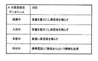
本実施形態では、データ格納部10Aは、第1の実施形態で示したDB101〜105に加えて、発信者の用件が緊急の場合に取るべき対応を記録する緊急設定DB106を備えている。図10は緊急設定DB106に格納された情報の一例である。図10では例えば、使用者Aが就寝中の場合において、発信者の用件が緊急のときは、音量を最大にして着信音を鳴らすことが規定されている。 In the present embodiment, the
制御部20Aは、緊急時対応部211を備えている。緊急時対応部211は、着信があった場合に、受信者特定部202によって特定された受信者が応答不能であると判断されたとき、この着信が緊急か否かを判断する。緊急か否かの判断は、送信した留守番メッセージに対する発信者の応答に基づいて、行う。例えば、留守番メッセージに、緊急時には所定番号をプッシュするようお願いする旨を付加しておき、その番号がプッシュされたか否かに応じて、緊急か否かを判断する。 The
そして、緊急と判断したとき、緊急時対応部211は、図10のような緊急設定データベース106を参照して、受信者の行動に応じた緊急時対応をとる。例えば、着信音設定部205に着信音の音量を最大に設定させるとともに、着信音起動部208に着信音を起動させる。これにより、発信者の緊急の要件がすぐに受信者に伝わる可能性が高くなる。それでも誰も着信に対し応答できない場合や、発信者の要件が緊急でない場合は、そのまま発信者の応答メッセージを記録する。 When it is determined that an emergency has occurred, the
以上のように本実施形態によると 使用者の行動に応じた緊急時の対応を管理する緊急設定DB106を用いて、緊急時対応部211が、着信が緊急と判断したとき、受信者の行動に応じた緊急時対応をとる。これにより、発信者の緊急の用件がすぐに受信者に伝わる可能性を高くなり、利便性が向上する。 As described above, according to the present embodiment, when the
(第3の実施形態)
図11は本発明の第3の実施形態に係る問い合わせ応答装置の構成を示すブロック図である。図11では、図1と共通の構成要素には図1と同一の符号を付しており、かつ、データ格納部10および制御部20Bのみを示しており、それ以外の構成要素については図示を省略する。(Third embodiment)
FIG. 11 is a block diagram showing a configuration of an inquiry response device according to the third embodiment of the present invention. In FIG. 11, the same reference numerals as those in FIG. 1 are given to the same components as in FIG. 1, and only the
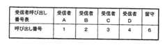
図12は図11の問い合わせ応答装置の動作を示すフローチャートである。図12において、着信があると、発信者識別部201および受信者特定部202Aは、発信者DB101を参照して、発信者と関係のある使用者がいるか否かを確認する(S31)。発信者が使用者の誰とも関係がないときは(S31でNo)、通常通り着信音を鳴らす(S32)。一方、関係のある使用者がいるときは(S31でYes)、受信者状況確認部203が使用者行動DB102を参照して応答可能な使用者を特定し、受信者特定部202Aからの指示を受けて、応答可能者通知部212が、応答可能な使用者を発信者に伝える(S33)。 FIG. 12 is a flowchart showing the operation of the inquiry response device of FIG. In FIG. 12, when there is an incoming call, the
このとき、応答可能者にそれぞれ対応している呼び出し番号も、併せて通知する。図13は呼び出し番号の一例である。発信者には例えば、「ただいまBとDが受信可能です。Bに用件があるときは2番を、Dに用件があるときは4番を押して下さい。また、それ以外の人に用件があるときは、6番を押してメッセージを入れて下さい。」というようなメッセージを送信する。 At this time, the call number corresponding to each responder is also notified. FIG. 13 shows an example of the call number. For example, “B and D can be received right now. Press B if there is a business in B, and
その後、応答可能者通知部212は、受信者に対応したボタンが発信者によって押されたか否かを判断する(S34)。そしてボタンが押されたときは(Yes)、着信音設定部205および着信音起動部208によってその受信者に対応した着信音を鳴らす(S36)。一方、ボタンが押されないときは(S34でNo)、メッセージ選択部204およびメッセージ送信部209によって留守番メッセージを送信し、着信履歴と伝言メッセージを記録する(S35)。 Thereafter, the responder notification unit 212 determines whether or not the button corresponding to the receiver has been pressed by the caller (S34). When the button is pressed (Yes), a ring tone corresponding to the recipient is played by the ring
以上のように本実施形態によると、応答可能者を通知して、送信者に、受信者を選択させることができるので、利便性が向上する。 As described above, according to the present embodiment, it is possible to notify the responder and allow the sender to select the receiver, so that convenience is improved.
なお、上述の各実施形態では、問い合わせ装置は固定電話機に付属しており、留守番電話機能を実現するものとして説明したが、本発明に係る問い合わせ応答装置は、インターネットにおけるEメールやネットミーティング、また来客者に応対する玄関のインターホンなどにも応用可能である。Eメールやネットミーティングの場合には、例えばネットワークに接続できるPCにおいて、本発明に係る問い合わせ応答装置は実現される。発信者の識別は、Eメールではメールアドレスによって、ネットミーティングではIPアドレスによって、それぞれ可能である。また発信者へのメッセージ送信は、ネットミーティングの場合は、一旦ミーティングに参加(接続)し、その場で留守番メッセージを送信(発言)するようにすればよい。その後、相手の発言をメッセージとして保存し、ミーティングへの参加を終了する。またEメールの場合は、返信するだけでよい。これらの機能を実現するためには、例えば専用のソフトウェアを準備し、PCにインストールすればよい。 In each of the above-described embodiments, the inquiry device is attached to the fixed telephone and has been described as realizing the answering machine function. However, the inquiry response device according to the present invention can be used for e-mail and network meetings on the Internet, It can also be applied to door intercoms that respond to visitors. In the case of e-mail or net meeting, for example, the inquiry response device according to the present invention is realized in a PC that can be connected to the network. The caller can be identified by e-mail address for e-mail and by IP address for net meeting. As for the message transmission to the caller, in the case of a net meeting, it is only necessary to once join (connect) to the meeting and transmit (speak) an answering message on the spot. After that, the other party's remarks are saved as a message, and participation in the meeting is terminated. In the case of e-mail, it is only necessary to reply. In order to realize these functions, for example, dedicated software may be prepared and installed in the PC.
そして、例えばEメールに関しては、受信装置としてのコンピュータに本発明の問い合わせ応答装置を付属させることによって、受信者がコンピュータを利用していない場合であっても、受信者が応答可能な状況にあるとき、Eメールが届いたことを受信者に知らせることができる。 For example, with regard to e-mail, by attaching the inquiry response device of the present invention to a computer as a receiving device, the recipient can respond even if the recipient does not use the computer. Sometimes, the recipient can be notified that the email has arrived.
また、受信装置としてのインターホンに本発明の問い合わせ装置を付属させた場合は、来客者すなわちインターホンの発信者の顔画像を、その個別情報として用いて、上述の各実施形態と同様に動作させればよい。すなわち、発信者DB101に発信候補者の顔画像を個別情報として管理しておき、来客時に、発信者識別部201が、インターホンのモニタに映った来客者の顔画像と発信者DB101に記録されている顔画像とを比較して、来客者を識別する。また、インターホンに、各使用者に対応するボタンと応答可能者の表示部を設けておくことによって、第3の実施形態と同様に、来客者に、用件のある人を指定してもらうことも可能である。 Further, when the interrogation device of the present invention is attached to the interphone as the receiving device, the face image of the visitor, that is, the caller of the interphone can be used as the individual information, and the operation can be performed in the same manner as in the above embodiments. That's fine. That is, the caller's face image is managed in the
また、本発明の問い合わせ装置をネットミーティングに導入した場合も、上述の各実施形態と同様に動作させればよいが、この場合、発信者側のディスプレイに各使用者の情報を予め開示しておくことが可能である。開示される内容は、発信者DB101に管理された親密度のデータを基に決定すればよい。また、緊急の場合は、受信者がネットミーティングに参加していないときでも、受信者が在宅なら固定電話の着信音を鳴らす、不在なら携帯電話の着信音を鳴らして緊急用件があることを伝える、といった対応も可能である。 In addition, even when the inquiry device of the present invention is introduced into a net meeting, it may be operated in the same manner as in the above embodiments. In this case, information on each user is disclosed in advance on the display on the caller side. It is possible to leave. The disclosed content may be determined based on the familiarity data managed by the
また、携帯電話のメールに関しても、本発明の問い合わせ応答装置は有効である。例えば、携帯電話の利用者は、在宅のときは携帯電話を常に身に付けている訳ではないし、また外出の際も周りの騒音によって着信に気づかない場合がある。この結果、メールの確認が長時間なされないままになってしまい、緊急を要するメールが相手になかなか伝わらないことがある。このような問題に対処するための本装置の動作をを、図14のフローチャートを参照して、説明する。 In addition, the inquiry response device of the present invention is also effective for e-mails of mobile phones. For example, a user of a mobile phone does not always wear the mobile phone when at home, and may not notice an incoming call due to surrounding noise when going out. As a result, the confirmation of the mail is not performed for a long time, and the urgent mail may not be easily transmitted to the other party. The operation of the present apparatus for coping with such a problem will be described with reference to the flowchart of FIG.
すなわち、携帯電話にメールが届いてから、所定時間内にそのメールがチェックされたか否かを確認する(S41)。チェックされているときは(Yes)通常待機にもどり(S42)、チェックされていないときは(No)メールの内容が緊急を要するものか否かを判断する(S43)。ここで、緊急を要するものか否かの判断は、図15に示すような、緊急であることを示す緊急語を記憶する緊急語DBを参照して、そのメールが、緊急語DBに記憶された緊急語を含むか否かに応じて、行う。メール中に緊急語が見つからないときは(No)通常待機にもどり(S42)、見つかったときは(Yes)、受信者が在宅か不在かを使用者行動DB102を参照して確認する(S44)。そして、不在であるときは(No)携帯電話の着信音を鳴らし(S45)、在宅なら固定電話機の着信音を鳴らし、受信者が応答したら携帯電話に緊急のメールが届いていることを伝える(S46)。 That is, it is confirmed whether or not the mail is checked within a predetermined time after the mail arrives at the mobile phone (S41). When it is checked (Yes), it returns to the normal standby (S42), and when it is not checked (No), it is judged whether or not the content of the mail is urgent (S43). Here, whether or not an emergency is required is determined by referring to an emergency word DB that stores an emergency word indicating an emergency as shown in FIG. 15, and the mail is stored in the emergency word DB. Depending on whether or not emergency words are included. When the emergency word is not found in the mail (No), return to the normal standby (S42), and when found (Yes), it is confirmed by referring to the
なお、上述の各実施形態では、家庭を例にとって説明したが、本発明の問い合わせ応答装置は、家庭以外の居住空間、例えばオフィスや病院においても利用することができる。 In each of the embodiments described above, the home has been described as an example. However, the inquiry response device of the present invention can be used in a living space other than the home, for example, an office or a hospital.
本発明に係る問い合わせ応答装置は、利用者に煩雑な作業を強いることなく、着信に対して的確に対応可能であり、また、受信装置に複数の使用者がいる場合でも、着信に対して的確に対応可能であるので、例えば家庭内の電話機のような受信装置に付属して用いるのに適している。 The inquiry response device according to the present invention can respond appropriately to an incoming call without forcing the user to perform complicated work. Also, even when there are a plurality of users in the receiving device, the inquiry response device can accurately respond to the incoming call. For example, it is suitable for use with a receiving device such as a home telephone.
1 受信装置
10,10A データ格納部
20,20A,20B 制御部
101 発信者データベース
102 使用者行動データベース
106 緊急設定データベースDESCRIPTION OF
Claims (11)
Translated fromJapanese前記受信装置の使用者について、少なくとも、居場所および行動を管理する使用者行動データベースと、
制御部とを備え、
前記制御部は、
前記受信装置に着信があったとき、発信先の個別情報から、発信者を識別し、
識別した発信者から、受信者を特定し、
前記使用者行動データベースを参照して、特定した受信者が、前記着信に応答可能か否かを判断する
ことを特徴とする問い合わせ応答装置。An inquiry response device attached to the receiving device in the living space,
For the user of the receiving device, at least a user behavior database for managing whereabouts and behaviors;
A control unit,
The controller is
When there is an incoming call to the receiving device, from the individual information of the destination, the caller is identified,
Identify the recipient from the identified caller,
An inquiry response device characterized by determining whether or not the identified receiver can respond to the incoming call by referring to the user behavior database.
前記受信装置は、電話機であり、
前記個別情報は、電話番号である
ことを特徴とする問い合わせ応答装置。In claim 1,
The receiving device is a telephone;
The inquiry response device, wherein the individual information is a telephone number.
前記制御部は、
前記受信者が応答可能と判断したとき、前記使用者行動データベースを参照して、前記受信者の居場所および行動に応じて、着信音の種類および音量のうち少なくとも1つを設定する
ことを特徴とする問い合わせ応答装置。In claim 1,
The controller is
When it is determined that the recipient can respond, the user behavior database is referred to, and at least one of the ringtone type and volume is set according to the location and behavior of the recipient. An inquiry response device.
前記使用者について、少なくとも、その行動に応じた緊急時の対応を管理する緊急設定データベースを備え、
前記制御部は、
前記受信者が応答不能と判断したとき、前記着信が、緊急か否かを判断し、
緊急と判断したとき、前記緊急設定データベースを参照して、前記受信者の行動に応じた緊急時対応をとる
ことを特徴とする問い合わせ応答装置。In claim 1,
For the user, at least an emergency setting database for managing an emergency response according to the action,
The controller is
When the receiver determines that the response is not possible, determines whether the incoming call is urgent,
An inquiry response device characterized in that, when it is determined to be urgent, the emergency setting database is referred to and an emergency response is taken according to the behavior of the recipient.
前記制御部は、
前記受信者が応答不能と判断したとき、前記発信者にメッセージを送信し、
送信したメッセージに対する前記発信者の応答に基づいて、前記着信が緊急か否かの判断を行う
ことを特徴とする問い合わせ応答装置。In claim 4,
The controller is
When the recipient determines that he cannot respond, sends a message to the caller;
An inquiry response device that determines whether the incoming call is urgent based on a response of the caller to a transmitted message.
緊急であることを示す緊急語を記憶する緊急語データベースを備え、
前記制御部は、
発信された情報がメールであるとき、前記着信が緊急か否かの判断を、前記緊急語データベースを参照して、前記メールが緊急語を含むか否かに応じて、行う
ことを特徴とする問い合わせ応答装置。In claim 4,
Equipped with an emergency word database that stores emergency words indicating urgency,
The controller is
When the transmitted information is a mail, it is determined whether or not the incoming call is urgent according to whether or not the mail includes an urgent word with reference to the urgent word database. Inquiry response device.
発信先の候補となる発信候補者について、少なくとも、その個別情報と、前記受信装置の各使用者との関係とを管理する発信者データベースと、
制御部とを備え、
前記制御部は、
前記受信装置に着信があったとき、前記発信者データベースを参照して、発信先の個別情報から、発信者を識別し、
識別した発信者から、前記発信者データベースを参照して、前記各使用者の中から受信者を特定する
ことを特徴とする問い合わせ応答装置。An inquiry response device attached to the receiving device in the living space,
For a transmission candidate as a transmission destination candidate, at least a caller database that manages the individual information and the relationship with each user of the receiving device;
A control unit,
The controller is
When there is an incoming call to the receiving device, refer to the caller database, identify the caller from the individual information of the callee,
An inquiry response device characterized in that, from the identified sender, the receiver database is specified with reference to the sender database.
前記受信装置は、電話機であり、
前記個別情報は、電話番号である
ことを特徴とする問い合わせ応答装置。In claim 7,
The receiving device is a telephone;
The inquiry response device, wherein the individual information is a telephone number.
前記発信者データベースは、発信候補者と各使用者との間の親密度を管理する
ことを特徴とする問い合わせ応答装置。In claim 7,
The caller database manages an intimacy between a caller candidate and each user.
前記制御部は、
特定した受信者が、応答可能か否かを判断し、
前記受信者が応答不能と判断したとき、前記発信者データベースに管理された,発信者と当該受信者との間の親密度に応じて、動作を決定する
ことを特徴とする問い合わせ応答装置。In claim 9,
The controller is
Determine if the identified recipient is available,
When the receiver determines that the response is impossible, the inquiry response device is characterized in that the operation is determined according to the familiarity between the sender and the receiver, which is managed in the sender database.
前記制御部は、
特定した受信者が、応答可能か否かを判断し、
前記受信者が応答不能と判断したとき、前記発信者データベースを参照して、次に親密度の高い使用者を、新たな受信者として特定する
ことを特徴とする問い合わせ応答装置。In claim 9,
The controller is
Determine if the identified recipient is available,
An inquiry response device characterized in that, when it is determined that the recipient is unable to respond, the next highest user is identified as a new recipient by referring to the sender database.
Priority Applications (1)
| Application Number | Priority Date | Filing Date | Title |
|---|---|---|---|
| JP2003280157AJP2005045724A (en) | 2003-07-25 | 2003-07-25 | Inquiry response device |
Applications Claiming Priority (1)
| Application Number | Priority Date | Filing Date | Title |
|---|---|---|---|
| JP2003280157AJP2005045724A (en) | 2003-07-25 | 2003-07-25 | Inquiry response device |
Publications (1)
| Publication Number | Publication Date |
|---|---|
| JP2005045724Atrue JP2005045724A (en) | 2005-02-17 |
Family
ID=34266072
Family Applications (1)
| Application Number | Title | Priority Date | Filing Date |
|---|---|---|---|
| JP2003280157APendingJP2005045724A (en) | 2003-07-25 | 2003-07-25 | Inquiry response device |
Country Status (1)
| Country | Link |
|---|---|
| JP (1) | JP2005045724A (en) |
Cited By (3)
| Publication number | Priority date | Publication date | Assignee | Title |
|---|---|---|---|---|
| JP2008522250A (en)* | 2005-12-27 | 2008-06-26 | 松下電工株式会社 | System and method for providing victim location information in an emergency |
| JP2009515469A (en)* | 2005-11-07 | 2009-04-09 | チッカ ピーティーイー リミテッド | Messaging system between operators with different buddy bases |
| JP2010220219A (en)* | 2009-03-16 | 2010-09-30 | Avaya Inc | Advanced availability detection |
- 2003
- 2003-07-25JPJP2003280157Apatent/JP2005045724A/enactivePending
Cited By (8)
| Publication number | Priority date | Publication date | Assignee | Title |
|---|---|---|---|---|
| JP2009515469A (en)* | 2005-11-07 | 2009-04-09 | チッカ ピーティーイー リミテッド | Messaging system between operators with different buddy bases |
| JP2008522250A (en)* | 2005-12-27 | 2008-06-26 | 松下電工株式会社 | System and method for providing victim location information in an emergency |
| JP2010220219A (en)* | 2009-03-16 | 2010-09-30 | Avaya Inc | Advanced availability detection |
| JP2010220220A (en)* | 2009-03-16 | 2010-09-30 | Avaya Inc | Advanced availability detection |
| US8484339B2 (en) | 2009-03-16 | 2013-07-09 | Avaya, Inc. | Advanced availability detection |
| US8499085B2 (en) | 2009-03-16 | 2013-07-30 | Avaya, Inc. | Advanced availability detection |
| US9092389B2 (en) | 2009-03-16 | 2015-07-28 | Avaya Inc. | Advanced availability detection |
| US9372824B2 (en) | 2009-03-16 | 2016-06-21 | Avaya Inc. | Advanced availability detection |
Similar Documents
| Publication | Publication Date | Title |
|---|---|---|
| CN100367320C (en) | Emergency call system and its control method | |
| CN1825875B (en) | Method and system for forwarding telephone calls based on presence information | |
| US6671508B1 (en) | Communication control method, status notification method and mobile communication terminal using same | |
| JP2008539629A (en) | Call control system and method | |
| JP4920516B2 (en) | Telephone system and proxy answering phone | |
| US8064487B1 (en) | Virtual office presence bridge | |
| JP2005045724A (en) | Inquiry response device | |
| JP2009147399A (en) | Telephone relaying device, telephone relaying method, and program for telephone relay | |
| JP2010239242A (en) | Automatic answering machine, automatic answering method and automatic answering program | |
| JP2004015159A (en) | Mobile phone communication system | |
| JP2003163760A (en) | Rescue request calling device and method | |
| JP2003158589A (en) | Anomaly notification method and communication terminal, CTI server, web server and anomaly automatic notification system used therefor | |
| JP5614805B2 (en) | Mail transmission method, portable terminal device, and mail transmission program | |
| JP2009239883A (en) | Telephone system having security function | |
| KR101185640B1 (en) | Communication device, communication system, and notification method | |
| JP2020182033A (en) | Intercom system | |
| EP2034711B1 (en) | Cellular phone | |
| JPH06121046A (en) | Connection reservation service control method | |
| JP2009088808A (en) | Mobile communication terminal | |
| JP2005244863A (en) | Call arrival response control apparatus and call arrival response/transfer control apparatus | |
| JP5298584B2 (en) | Information terminal, server device, and information processing method | |
| KR100672358B1 (en) | Automatic response message transmission device and transmission method using mobile communication terminal | |
| JP6677888B2 (en) | Telephone | |
| JP2024044749A (en) | Message processing system, information terminal control method, message processing method, message processing program, and information terminal control program | |
| JP2002359685A (en) | Voice memo recording and reproducing device |