JP2005032575A - Direct backlight - Google Patents
Direct backlightDownload PDFInfo
- Publication number
- JP2005032575A JP2005032575AJP2003271123AJP2003271123AJP2005032575AJP 2005032575 AJP2005032575 AJP 2005032575AJP 2003271123 AJP2003271123 AJP 2003271123AJP 2003271123 AJP2003271123 AJP 2003271123AJP 2005032575 AJP2005032575 AJP 2005032575A
- Authority
- JP
- Japan
- Prior art keywords
- light source
- divided body
- frame
- divided
- light
- Prior art date
- Legal status (The legal status is an assumption and is not a legal conclusion. Google has not performed a legal analysis and makes no representation as to the accuracy of the status listed.)
- Pending
Links
- 230000001678irradiating effectEffects0.000claimsabstractdescription3
- 235000012438extruded productNutrition0.000claimsdescription3
- 238000013461designMethods0.000abstractdescription8
- 230000008878couplingEffects0.000abstractdescription5
- 238000010168coupling processMethods0.000abstractdescription5
- 238000005859coupling reactionMethods0.000abstractdescription5
- 238000001125extrusionMethods0.000description11
- 238000009792diffusion processMethods0.000description9
- 239000004973liquid crystal related substanceSubstances0.000description9
- 229910052751metalInorganic materials0.000description7
- 239000002184metalSubstances0.000description7
- 238000012545processingMethods0.000description7
- 125000006850spacer groupChemical group0.000description6
- 238000003780insertionMethods0.000description5
- 230000037431insertionEffects0.000description5
- 238000004519manufacturing processMethods0.000description4
- 238000000034methodMethods0.000description3
- 229910052782aluminiumInorganic materials0.000description2
- XAGFODPZIPBFFR-UHFFFAOYSA-NaluminiumChemical compound[Al]XAGFODPZIPBFFR-UHFFFAOYSA-N0.000description2
- 230000005540biological transmissionEffects0.000description2
- 238000002347injectionMethods0.000description2
- 239000007924injectionSubstances0.000description2
- 238000001746injection mouldingMethods0.000description2
- 238000003825pressingMethods0.000description2
- 239000011347resinSubstances0.000description2
- 229920005989resinPolymers0.000description2
- GWEVSGVZZGPLCZ-UHFFFAOYSA-NTitan oxideChemical compoundO=[Ti]=OGWEVSGVZZGPLCZ-UHFFFAOYSA-N0.000description1
- 229910001361White metalInorganic materials0.000description1
- 239000000853adhesiveSubstances0.000description1
- 230000001070adhesive effectEffects0.000description1
- 238000005520cutting processMethods0.000description1
- 230000001771impaired effectEffects0.000description1
- 238000012986modificationMethods0.000description1
- 230000004048modificationEffects0.000description1
- 239000003973paintSubstances0.000description1
- 230000002035prolonged effectEffects0.000description1
- 230000005855radiationEffects0.000description1
- 230000000630rising effectEffects0.000description1
- OGIDPMRJRNCKJF-UHFFFAOYSA-Ntitanium oxideInorganic materials[Ti]=OOGIDPMRJRNCKJF-UHFFFAOYSA-N0.000description1
- 239000010969white metalSubstances0.000description1
Images


Landscapes
- Liquid Crystal (AREA)
- Planar Illumination Modules (AREA)
- Optical Elements Other Than Lenses (AREA)
Abstract
Description
Translated fromJapanese本発明は、直下型バックライトに関するものである。 The present invention relates to a direct type backlight.
直下型バックライトは、例えば、液晶表示装置の液晶パネルの背後に配置され、液晶パネルに光を照射するために使用されるものであり、拡散板の背後に冷陰極管ランプなどの光源を配置して構成されている。
光源は、拡散板が配置される面が開口した箱状のランプハウスに収容されている。ランプハウスは、金属又は樹脂製であるのが一般的であり、プレス加工や射出成型によって形成される。このため、ランプハウスを製作するためには、非常に高額なプレス金型や射出成型金型が必要とされている。
The light source is accommodated in a box-shaped lamp house having an open surface on which the diffusion plate is disposed. The lamp house is generally made of metal or resin, and is formed by pressing or injection molding. For this reason, in order to manufacture a lamp house, very expensive press molds and injection molds are required.
従来、直下型バックライトのランプハウスなどの構成部材は、新機種毎に新たに設計されており、その度に金型を作製する必要がある。
このため、新機種の設計時間の長期化やコスト高を招いていた。結果的に、従来の直下型バックライト構造では、新機種設計又は設計変更に柔軟に対応することができなかった。Conventionally, components such as a lamp house of a direct type backlight are newly designed for each new model, and it is necessary to produce a mold each time.
For this reason, the design time of the new model is prolonged and the cost is increased. As a result, the conventional direct type backlight structure cannot flexibly cope with a new model design or a design change.
本発明は、被照射体へ光を照射する光源と、当該光源の背後に位置する面を有する反射面フレームと、を有する直下型バックライトにおいて、前記反射面フレームは、複数の分割体を連結して構成されていることを特徴とする。
複数の分割体を連結して反射面フレームが構成されるため、連結される分割体の数を変えることで反射面フレームの大きさを変えることができる。したがって、反射面フレームの大きさ変更を伴う新機種設計等には簡単に対応することができる。The present invention provides a direct-type backlight having a light source for irradiating light to an irradiated object and a reflective surface frame having a surface located behind the light source, wherein the reflective surface frame connects a plurality of divided bodies. It is characterized by being comprised.
Since the reflective surface frame is configured by connecting a plurality of divided bodies, the size of the reflective surface frame can be changed by changing the number of divided bodies to be connected. Therefore, it is possible to easily cope with a new model design accompanied by a change in the size of the reflecting surface frame.
前記分割体は、押出加工品又は引抜加工品であるのが好ましい。押出加工品又は引抜加工品であれば、コスト高を招くことなく、分割体の長さを自由に選択できる。したがって、分割体の長さ又は連結数を適宜選択することにより、簡単に反射面フレームの大きさを変更することができる。 The divided body is preferably an extruded product or a drawn product. In the case of an extruded product or a drawn product, the length of the divided body can be freely selected without increasing the cost. Therefore, the size of the reflective surface frame can be easily changed by appropriately selecting the length of the divided bodies or the number of connections.
前記分割体は、前記光源に対面する面が反射凹面とされ、前記光源は、前記凹面の頂部よりも高い位置に配置されているのが好ましい。光源が反射凹面頂部よりも高い位置に配置されていることで、凹面頂部への光の照射も得られて、反射凹面による反射光を均一化できる。 In the divided body, a surface facing the light source is preferably a reflective concave surface, and the light source is preferably disposed at a position higher than the top of the concave surface. Since the light source is arranged at a position higher than the top of the reflective concave surface, light irradiation to the top of the concave surface can also be obtained, and the reflected light from the reflective concave surface can be made uniform.
前記分割体は、前記光源に対面する面が拡散反射面とされているのが好ましい、反射面が鏡面反射面(正反射面)である場合よりも、拡散反射面の方がランプイメージを改善できる。 The split body preferably has a diffuse reflection surface on the surface facing the light source. The diffuse reflection surface improves the lamp image compared to the case where the reflection surface is a specular reflection surface (regular reflection surface). it can.
他の観点からみた本発明は、光源と、前記光源に対面する面が凹状である断面形状を有するとともに、当該断面形状が長手方向に同一である長尺状の分割体と、前記分割体に取り付けられた光源保持具と、を有して光源付き分割形ユニットが構成され、複数の前記光源付き分割形ユニットが、前記分割体の長手方向に対して直交する方向に並んで連結されていることを特徴とする直下型バックライトである。連結されるユニットの数を変えることで簡単にバックライトの大きさを変更することができる。 From another viewpoint, the present invention includes a light source, a long divided body having a concave cross-sectional surface facing the light source, and a long divided body having the same cross-sectional shape in the longitudinal direction. A split light source holder, and a plurality of split light source units are connected side by side in a direction orthogonal to the longitudinal direction of the split body. This is a direct backlight. The size of the backlight can be easily changed by changing the number of connected units.
本発明によれば、バックライトのサイズの変更に容易に対応することができる。 According to the present invention, it is possible to easily cope with a change in the size of the backlight.
以下、本発明の実施形態を図面に基づいて説明する。
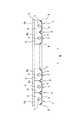
図1は、液晶表示装置の液晶パネルの背後に配置され、被照射体である液晶パネルに対して光を照射する直下型バックライト1を示している。このバックライト1は、矩形状の拡散板(光透過面部材)2と、光源3を含む装置本体4とを備えている。光源3の光は、拡散板2によって拡散されてほぼ均一な面状光が形成され、被照射体である液晶パネルに照射される。Hereinafter, embodiments of the present invention will be described with reference to the drawings.
FIG. 1 shows a direct-type backlight 1 that is disposed behind a liquid crystal panel of a liquid crystal display device and irradiates light onto a liquid crystal panel that is an object to be irradiated. The backlight 1 includes a rectangular diffusion plate (light transmission surface member) 2 and an apparatus main body 4 including a
装置本体4は、光源3の背後に位置する反射面フレーム5と、反射面フレーム5に取り付けられた光源保持具6と、光源保持具6によって保持された光源3とを有している。
反射面フレーム5は、光源3からの光を拡散板2側へ反射する光反射機能を担うためのものであり、平面視矩形状であって、複数の分割体7の組み合わせによって構成されている。図2に示すように、分割体7は、底部8と、底部8から幅方向両側において立ち上がった側部9,9と、を有して断面が凹状であって、長手方向に断面形状が同一である長尺状の部材として形成されている。なお、凹状分割体の内面が光源3と対向する反射凹面となる。The apparatus main body 4 includes a reflective surface frame 5 located behind the
The reflection surface frame 5 is for carrying a light reflection function of reflecting light from the
分割体7は、押出機を用いてアルミニウムなどの金属を押出加工することによって形成されている。押出機は、前記分割体7の断面形状に対応した押出型を具備しており、図2に示すような断面形状が長手方向に同一である長尺状の分割体7を形成することができる。また、押出加工であるから、分割体7の長手方向A長さは自由に設定することができる。したがって、分割体によって構成されるフレーム5の方向Aの長さを自由に設定できる。 The divided
図1に示すように複数の分割体7が、幅方向B(長手方向と直交する方向)に並べられ、隣接する分割体7,7の側部9,9の上端同士が接触するように配置されて一つのフレーム5が形成される。一つの反射面フレーム5を構成する分割体7の数を変えることによって、方向Bの長さを自由に設定できる。例えば、幅方向B長さが20mmである分割体を14個並べると20インチ液晶表示装置用バックライトとして適した大きさとなる(長手方向A長さは420mm程度)。
このように、単一の型を用いても、フレーム5の方向A,Bの長さを自由に設定できる。As shown in FIG. 1, a plurality of divided
In this way, the lengths of the directions A and B of the frame 5 can be freely set even if a single mold is used.
フレーム5全体をプレスや射出成形で一体的に形成する場合には、非常に高額なプレス金型や射出成形金型が必要となり、特にサイズが大きくなるに従い金型コストが増加する。一方、本実施形態のもののように押出加工の場合には、押出型のコストが安いため製造コストを抑えることができる。また、フレーム5のサイズが大きくなっても型の変更なしで対応できるため、コストを低減できる。つまり、一つの押出型をいくつかのフレームサイズについて共用できるし、フレームサイズに変更があった場合でも短期間で簡単に対応することができる。この結果、形成される分割体7の断面形状が異なるいくつかの押出型を用意しておくことで、非常に多くのタイプのフレームを製作することが可能となる。 When the entire frame 5 is integrally formed by press or injection molding, a very expensive press mold or injection mold is required, and the mold cost increases particularly as the size increases. On the other hand, in the case of extrusion processing as in the present embodiment, the manufacturing cost can be reduced because the cost of the extrusion die is low. Further, since the size of the frame 5 can be increased without changing the type, the cost can be reduced. That is, one extrusion die can be shared for several frame sizes, and even when the frame size is changed, it can be easily dealt with in a short period of time. As a result, by preparing several extrusion dies having different cross-sectional shapes of the divided
さらに、30インチを超える大型の液晶表示装置用のバックライトでは、フレーム5も非常に大きくなるが、反射フレーム5は、均一な反射光を得るために歪みが少ないことが要求される。しかし、板金プレス加工で大型のフレームを歪みなく製作するのは非常に困難である。一方、押出加工による複数の分割体7の組み合わせによって反射フレームを構成すれば、フレームを大きくしても歪みが生じ難い。 Further, in the backlight for a large-sized liquid crystal display device exceeding 30 inches, the frame 5 is also very large, but the reflection frame 5 is required to have little distortion in order to obtain uniform reflected light. However, it is very difficult to produce a large frame without distortion by sheet metal pressing. On the other hand, if a reflective frame is formed by a combination of a plurality of divided
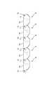
図4に示すように、各分割体7には、光源保持具6が取り付けられ、当該光源保持具6は光源3を保持している。分割体7、光源保持具6、及び光源3の組み合わせは、光源付きの分割形ユニット11を構成している。
分割形ユニット11は、分割体7の長手方向両側に光源保持具6,6がそれぞれ取り付けられ、両光源保持具6,6間に線状光源(冷陰極管ランプ)3が設けられている。なお、図示していないが、線状光源3の長手方向両端からはリード線が延設されており、光源保持具6,6を貫通して当該光源保持具6,6からユニット11外に延びている。As shown in FIG. 4, a
In the
光源保持具6,6は、接着剤又はネジなどの適宜固定手段によって分割体7に取り付けられている。保持具6,6は、分割体7の側面よりも高く形成されている。この保持具6の幅方向一方側には、側方に突出する突出片13が形成されている。図5に示すように、保持具6,6間に配置された光源3は、分割体側部9の高さh1よりも高い位置h2に位置するように位置設定されている。図1に示すように、分割体7の内面の集合で構成される反射面は、山と谷を有しており、反射面の山となる側部9の頂部よりも光源3が高い位置に存在することで、側部9頂部にも上方から光が当たり、拡散板2へ向かう反射光が得られる。これに対し、光源3が側部9の頂部よりも低い位置にしかない場合には、側部9の頂部に光が当たらないため、拡散板2側からみると当該頂部が暗部となって発光均一性が損なわれる。 The
光源3からの光の反射凹面となる分割体7内面には、酸化チタンを含む白色塗料を塗装したり、白色シート又はフィルムを張り付けたりすることで拡散反射面が得られる。また、分割体7がアルミニウムなどの白色金属の場合、表面に細かい凹凸をつけて拡散反射面にしたり、拡散反射させるための凹凸のあるドットをプレス加工によってつけてもよい。 A diffuse reflection surface is obtained by applying a white paint containing titanium oxide or pasting a white sheet or film on the inner surface of the divided
光源保持具6は、分割形ユニット11同士を連結するための連結具でもある。連結具として機能するため保持具6には、幅方向一方側から外側方に突出する突出片13を有し、この突出片13には第1ネジ挿通孔14が貫通形成されている。また、保持具6の幅方向他方側には、前記第1ネジ挿通孔14と同じ高さ位置に第2ネジ挿通孔15が貫通形成されている。図6に示すように複数の分割形ユニット11を並べて、隣接するユニット11の第1ネジ挿通孔14と第2ネジ挿通孔15とを重ね合わせて図示しないネジで両連結具6を結合することによって、各ユニット11同士が固定される。このとき、各ユニット11の分割体底部8が同一平面内に位置するように結合することで、整列された結合状態が得られる。 The
このように、光源付きの分割形ユニット11を構成しておき、複数のユニット11を結合することでバックライト1を構成すると、様々なサイズに容易に対応することができる。また、光源保持具6も複数個を連結することによって全体が構成されるため、バックライト1のサイズが変更されても容易に対応することができ、設計や試作が容易である。また、保持具6を製作する金型も小さくて済むため、コストを低減できる。 Thus, when the
保持具6は、拡散板2の支持具でもあり、支持具6の上面6aは拡散板2が載せられる載置面となっている。拡散板2の載置面6aは、支持具6の上端面である必要はなく、例えば、支持具6の上端面に対して段差が生じるように上端面よりも低い面であってもよい。拡散板2の載置面6aは、複数の支持具6を連結したときに全体として同一平面内に位置するように形成されており、拡散板2を安定的に置くことができる。 The
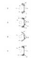
分割体7の断面形状は、様々なものを採用できるが、好ましくは、図7に示すように底部8と側部9を有して光源3を囲む内面が形成されるものがよい。底部8と側部9を有していることで長尺状分割体の歪みが効果的に防止される。特に、底部8(反射面としての機能が大きい)の平滑性が確保できる。具体的には、側部9は底部8に対して垂直方向に立設することができる(図7(a)参照)。あるいは、側部9が曲面状にすることができる(図7(b)(c)参照)。側部9を曲面状にする場合、上部が外向きになるように湾曲させてもよいし(図7(b)参照)、上部が真上を向くように湾曲させてもよい(図7(c)参照)。また、V字状のように底部8が広がりをもっていないものであってもよく、(図7(d)参照)、底部8が湾曲したU字状であってもよい(図7(e)参照)。 Various cross-sectional shapes can be adopted for the divided
さらに、一つの分割体7が複数の底部8を有する形状であってもよく、例えば、図5の分割体7を2つ組み合わせた2連形状であってもよい(図7(f)参照)。複数の底部8を有する分割体7の場合、底部8の数に対応させて一つのユニット11内に複数の光源3を設けるのが好ましい。 Furthermore, the shape which has the some
図8に示すように、分割体7は、外面(光源3と対向する反射面とは反対の面)に放熱フィン17のような突起を一体的に備えることができる。放熱フィン17は、側部9外面に突出状に形成してもよいし(図8(a)参照)、底部8に形成してもよい(図8(b)参照)。あるいは側部9と底部8の両方に形成してもよい(図8(c)参照)。また、放熱フィン17は、側部9,9を中空状にしたものであってもよい(図8(d)参照)。板金プレス加工等に比べて、押出加工の場合、図8(a)〜(d)の形状は簡単に形成することができ、放熱フィン17を分割体7と一体的に形成するのに適している。なお、追加の加工を行わない限り、押出加工によって図8(a)〜(d)の形状を形成した場合、当該形状は長手方向に連続したものとなる。 As shown in FIG. 8, the divided
図9は、分割体7の外面に、インバータ(光源点灯装置)18などの回路基板を取り付けるためのスペーサ19を形成した例を示している。インバータ18をフレームに取り付ける場合、インバータ18の絶縁のためにフレームから浮かした構造を取りたい場合がある。この場合、板金加工フレームであると、フレームの一部に切り込みを入れて折り返すなどしてインバータ取付け用のスペーサを形成することができるが、フレームに貫通孔があいてその孔から異物が進入するおそれがある。また、孔をあけずにスペーサを設けるには別体のスタッドピンを取り付けることも考えられるが、別体のものを取り付けるとコスト高となる。 FIG. 9 shows an example in which a
これに対し、押出加工の場合、板金加工では困難な図9のように分割体7を形成でき、分割体7に貫通孔をあけることなく一体的にスペーサ19を形成するため、異物進入を防止しつつ、安価に強固なスペーサ19が得られる。 On the other hand, in the case of extrusion processing, the divided
図10及び図11は、光源保持具6の変形例を示している。この光源保持具6は、取り付けられる分割体7の側部9より高い位置において、幅方向一方側に連結用リブ21が形成され、幅方向他方側に連結用溝22が形成されている。この光源保持具6を備えたユニット11同士を連結する場合には、図11に示すように、リブ21を隣接するユニット11の溝22に嵌合させることでユニット11同士が結合される。リブ21と溝22の連結構造の場合、ネジを用いないため連結が簡単である。なお、光源保持具6には、線状光源3の長手方向両端に設けられたゴムホルダが挿通されて光源3を固定する固定孔23が形成されている。 10 and 11 show a modification of the
本発明は、上記実施形態に限定されるものではない。例えば、分割体は、押出加工ではなく、引抜加工によっても形成できる。引抜加工であっても、上述した分割体の形状を形成することができる。また、光源を線状光源とする場合、棒状の樹脂体にLED光源からの光を導光し、線状に発光させるものであってもよい。 The present invention is not limited to the above embodiment. For example, the divided body can be formed not by extrusion but also by drawing. Even in the drawing process, the shape of the above-described divided body can be formed. Moreover, when using a light source as a linear light source, the light from an LED light source may be guided to a rod-shaped resin body, and light may be emitted linearly.
1 バックライト
2 拡散板(光透過面部材)
3 光源
4 装置本体
5 反射面フレーム
6 光源保持具
7 分割体
8 底部
9 側部
11 分割形ユニット1
DESCRIPTION OF
Claims (5)
Translated fromJapanese前記反射面フレームは、複数の分割体を連結して構成されていることを特徴とする直下型バックライト。In a direct type backlight having a light source for irradiating light to an irradiated object and a reflective surface frame having a surface located behind the light source,
The direct-type backlight, wherein the reflective surface frame is configured by connecting a plurality of divided bodies.
前記光源は、前記反射凹面の頂部よりも高い位置に配置されていることを特徴とする請求項1又は2に記載の直下型バックライト。In the divided body, a surface facing the light source is a reflective concave surface,
The direct-type backlight according to claim 1, wherein the light source is disposed at a position higher than a top portion of the reflective concave surface.
前記光源に対面する面が凹状である断面形状を有するとともに、当該断面形状が長手方向に同一である長尺状の分割体と、
前記分割体に取り付けられた光源保持具と、
を有して光源付き分割形ユニットが構成され、
複数の前記光源付き分割形ユニットが、前記分割体の長手方向に対して直交する方向に並んで連結されていることを特徴とする直下型バックライト。A light source;
While having a cross-sectional shape in which the surface facing the light source is concave, the long divided body having the same cross-sectional shape in the longitudinal direction;
A light source holder attached to the divided body;
A split-type unit with a light source is configured,
A direct type backlight, wherein the plurality of divided units with light sources are connected side by side in a direction orthogonal to the longitudinal direction of the divided body.
Priority Applications (1)
| Application Number | Priority Date | Filing Date | Title |
|---|---|---|---|
| JP2003271123AJP2005032575A (en) | 2003-07-04 | 2003-07-04 | Direct backlight |
Applications Claiming Priority (1)
| Application Number | Priority Date | Filing Date | Title |
|---|---|---|---|
| JP2003271123AJP2005032575A (en) | 2003-07-04 | 2003-07-04 | Direct backlight |
Publications (1)
| Publication Number | Publication Date |
|---|---|
| JP2005032575Atrue JP2005032575A (en) | 2005-02-03 |
Family
ID=34209094
Family Applications (1)
| Application Number | Title | Priority Date | Filing Date |
|---|---|---|---|
| JP2003271123APendingJP2005032575A (en) | 2003-07-04 | 2003-07-04 | Direct backlight |
Country Status (1)
| Country | Link |
|---|---|
| JP (1) | JP2005032575A (en) |
Cited By (6)
| Publication number | Priority date | Publication date | Assignee | Title |
|---|---|---|---|---|
| JP2006286639A (en)* | 2005-04-01 | 2006-10-19 | Avago Technologies General Ip (Singapore) Private Ltd | Light emitting device having a plurality of overlapping panels forming recess for emitting light |
| JP2007178988A (en)* | 2005-12-26 | 2007-07-12 | Lg Phillips Lcd Co Ltd | Backlight unit and liquid crystal display device including the same |
| JP2011077047A (en)* | 2010-11-24 | 2011-04-14 | Tousui Ltd | Led lighting fixture |
| JP4795357B2 (en)* | 2005-09-02 | 2011-10-19 | 古河電気工業株式会社 | Light reflector |
| US20130111754A1 (en)* | 2011-11-09 | 2013-05-09 | Tsai-Yuan Wei | Method of manufacturing heat sink frames |
| JP2017220444A (en)* | 2016-06-07 | 2017-12-14 | ルーメンス カンパニー リミテッド | Linear led module and backlight unit including the same |
- 2003
- 2003-07-04JPJP2003271123Apatent/JP2005032575A/enactivePending
Cited By (8)
| Publication number | Priority date | Publication date | Assignee | Title |
|---|---|---|---|---|
| JP2006286639A (en)* | 2005-04-01 | 2006-10-19 | Avago Technologies General Ip (Singapore) Private Ltd | Light emitting device having a plurality of overlapping panels forming recess for emitting light |
| JP4795357B2 (en)* | 2005-09-02 | 2011-10-19 | 古河電気工業株式会社 | Light reflector |
| JP2007178988A (en)* | 2005-12-26 | 2007-07-12 | Lg Phillips Lcd Co Ltd | Backlight unit and liquid crystal display device including the same |
| US7859609B2 (en) | 2005-12-26 | 2010-12-28 | Lg Display Co., Ltd. | Backlight unit and liquid crystal display device having the same |
| JP2011077047A (en)* | 2010-11-24 | 2011-04-14 | Tousui Ltd | Led lighting fixture |
| US20130111754A1 (en)* | 2011-11-09 | 2013-05-09 | Tsai-Yuan Wei | Method of manufacturing heat sink frames |
| JP2017220444A (en)* | 2016-06-07 | 2017-12-14 | ルーメンス カンパニー リミテッド | Linear led module and backlight unit including the same |
| US10429031B2 (en) | 2016-06-07 | 2019-10-01 | Lumens Co., Ltd. | Linear LED module and backlight unit including the same |
Similar Documents
| Publication | Publication Date | Title |
|---|---|---|
| CN102635794B (en) | Lighting device | |
| CN102893086A (en) | Light emitting device, and structure for attaching light emitting device | |
| US20080060244A1 (en) | Frame for a display apparatus and display apparatus having the same | |
| KR100687058B1 (en) | Back light and liquid crystal display for light emitting device, liquid crystal display | |
| US7722229B2 (en) | Frame design and backlight system using the same | |
| US9588364B2 (en) | Display device | |
| JP2005032575A (en) | Direct backlight | |
| JP4097655B2 (en) | Backlight device and display device having the same | |
| JP3894897B2 (en) | Backlight device | |
| JP5050876B2 (en) | LCD module | |
| JP2013026528A (en) | Light emitting device and display device | |
| JP2002258764A (en) | Backlight and display device | |
| CN100419527C (en) | Backlight module | |
| CN102401288B (en) | Backlight system | |
| JP2006216512A (en) | Flat lighting system | |
| KR102436466B1 (en) | Case member and liquid crystal display device comprising the same | |
| CN207661562U (en) | A kind of ultra-thin straight-down negative luminescent panel lamp of New LED | |
| JP2004022352A (en) | Backlight device | |
| CN116601555A (en) | Backlight module and display device | |
| CN218626600U (en) | Lens and lamp strip | |
| JP2008159390A (en) | Lighting system | |
| CN219976273U (en) | Spliced aluminum frame and display device | |
| CN214409372U (en) | Light emitting display device and backlight module thereof | |
| CN211293534U (en) | Side-in backlight module with stable fixed front frame | |
| JPH08152623A (en) | Back light unit for liquid crystal display device |
Legal Events
| Date | Code | Title | Description |
|---|---|---|---|
| A621 | Written request for application examination | Free format text:JAPANESE INTERMEDIATE CODE: A621 Effective date:20060421 | |
| A711 | Notification of change in applicant | Free format text:JAPANESE INTERMEDIATE CODE: A711 Effective date:20061115 | |
| A977 | Report on retrieval | Free format text:JAPANESE INTERMEDIATE CODE: A971007 Effective date:20080829 | |
| A131 | Notification of reasons for refusal | Free format text:JAPANESE INTERMEDIATE CODE: A131 Effective date:20080903 | |
| A02 | Decision of refusal | Free format text:JAPANESE INTERMEDIATE CODE: A02 Effective date:20090311 |