JP2005024176A - Humidification amount control method and vaporization type humidifier in vaporization type humidification - Google Patents
Humidification amount control method and vaporization type humidifier in vaporization type humidificationDownload PDFInfo
- Publication number
- JP2005024176A JP2005024176AJP2003190312AJP2003190312AJP2005024176AJP 2005024176 AJP2005024176 AJP 2005024176AJP 2003190312 AJP2003190312 AJP 2003190312AJP 2003190312 AJP2003190312 AJP 2003190312AJP 2005024176 AJP2005024176 AJP 2005024176A
- Authority
- JP
- Japan
- Prior art keywords
- humidification
- vaporizing
- humidifier
- humidity
- water
- Prior art date
- Legal status (The legal status is an assumption and is not a legal conclusion. Google has not performed a legal analysis and makes no representation as to the accuracy of the status listed.)
- Pending
Links
- 230000008016vaporizationEffects0.000titleclaimsabstractdescription90
- 238000009834vaporizationMethods0.000titleclaimsabstractdescription40
- 238000000034methodMethods0.000titleclaimsdescription28
- XLYOFNOQVPJJNP-UHFFFAOYSA-NwaterSubstancesOXLYOFNOQVPJJNP-UHFFFAOYSA-N0.000claimsabstractdescription92
- 238000010438heat treatmentMethods0.000claimsdescription7
- 238000010981drying operationMethods0.000claimsdescription3
- 238000001514detection methodMethods0.000claimsdescription2
- 238000007599dischargingMethods0.000abstractdescription2
- 239000000463materialSubstances0.000description8
- 238000010586diagramMethods0.000description6
- 235000019645odorNutrition0.000description5
- 239000000843powderSubstances0.000description5
- 241000894006BacteriaSpecies0.000description4
- 238000009434installationMethods0.000description4
- 239000000428dustSubstances0.000description3
- 239000007788liquidSubstances0.000description3
- 239000007921spraySubstances0.000description3
- 238000004378air conditioningMethods0.000description2
- 238000007664blowingMethods0.000description2
- 230000000694effectsEffects0.000description2
- 238000001704evaporationMethods0.000description2
- 230000008020evaporationEffects0.000description2
- 238000007605air dryingMethods0.000description1
- 230000003749cleanlinessEffects0.000description1
- 238000007796conventional methodMethods0.000description1
- 230000001877deodorizing effectEffects0.000description1
- 230000005611electricityEffects0.000description1
- 238000004519manufacturing processMethods0.000description1
- 230000003068static effectEffects0.000description1
- 239000008400supply waterSubstances0.000description1
- 239000002699waste materialSubstances0.000description1
Images


Landscapes
- Air Humidification (AREA)
- Air Conditioning Control Device (AREA)
Abstract
Translated fromJapaneseDescription
Translated fromJapanese【0001】
【発明の属する技術分野】
本発明は、気化式加湿における加湿量制御方法及び気化式加湿器に関するものである。
【0002】
【従来の技術】
空気の乾燥に起因する静電気によるトラブルの発生等を防止するために、従来から種々の加湿器が用いられている。その加湿方法としては、蒸気を直接噴霧する蒸気加湿方式と、エアワッシャ式や超音波式あるいは濡れ壁を用いた気化式加湿方式等、水表面からの蒸発を利用したものに分けられる。後者は、気化熱を奪うことから空気側の温度は低下するが、蒸気を発生する高位のエネルギーを利用する必要がないことから、省エネルギーや安全面から利用価値が高い。
【0003】
しかしながら、上記超音波式加湿器には、水分が蒸発した後に残留成分が白い粉となって残るという問題点や、水温が上昇することにより菌が発生するといった問題点があり、また、エアワッシャ式においても、加湿飽和効率を良くするために噴霧液滴を小さくすると、超音波式加湿器と同様に白い粉が発生するという問題点があった。このため、近年は水滴が出ない方式の気化式加湿器が注目されている。
【0004】
ところで、加湿を必要とする分野は一般空調、産業空調を問わないが、特に、産業分野では精密な加湿量制御を求められることが多い。このような加湿量の制御方法としては、例えば、特許文献1に示すような技術が知られている。
【0005】
【特許文献1】
特開2001−317795号公報
【0006】
【発明が解決しようとする課題】
しかしながら、上述したような従来の加湿量の制御方法には、以下に述べるような問題点があった。すなわち、従来のエアワッシャ型加湿器における加湿量の制御方法は、ワッシャー水ポンプのON,OFF制御であったため、精密な加湿量制御ができず、室温も大きく変動していた。
【0007】
また、ワッシャー方式のため、ワッシャーポンプの動力が大きく、加湿飽和効率が低く(言い換えれば、加湿能力が低く)、エリミネーターの圧損が大きいため、ファンの動力が大きくなり、騒音が大きいという欠点があった。
【0008】
さらに、市水を補給水としているため、加湿飽和効率を上げるために噴霧水滴を小さくしようとすると「白い粉」が出るという問題点があり、CR電子部品工場では、吹出口にHEPAフィルタを設置する必要があり、その結果、送風機の圧損が大きくなり、騒音も大きくなっていた。
【0009】
本発明は、上述したような従来技術の問題点を解決するために提案されたものであり、その目的は、高精度の加湿量制御を可能とし、騒音の発生を防止することができる気化式加湿における加湿量制御方法及び気化式加湿器を提供することにある。
【0010】
【課題を解決するための手段】
上記の目的を達成するために、請求項1に記載の発明は、加湿飽和効率が80%以上の気化式加湿ユニットと、送風機と、この送風機の駆動源であるモータの回転を制御する制御器と、加湿対象となる室内の湿度を測定する湿度センサとを用いて、加湿対象となる室内の加湿量を制御する気化式加湿における加湿量制御方法であって、予め設定された湿度と前記湿度センサによって検出された現在の湿度との差に基づいて送風量を制御し、加湿対象となる室内の必要加湿量を供給することができるように、前記送風機のモータの回転を制御することを特徴とするものである。
【0011】
また、請求項2に記載の気化式加湿器は、加湿飽和効率が80%以上の気化式加湿ユニットと、前記気化式加湿ユニットに対して加湿用水を給排水する給水ライン及び排水ラインと、送風機と、この送風機の駆動源であるモータの回転を制御する信号を出力する制御器と、加湿対象となる室内の湿度を測定し、その検出値を前記制御器に送出する湿度センサとを備え、前記制御器は、予め設定された湿度と前記湿度センサによって検出された現在の湿度との差に基づいて送風量を制御し、加湿対象となる室内の必要加湿量を供給することができるように、前記送風機のモータの回転を制御する信号を出力するように構成されていることを特徴とするものである。
【0012】
上記のような構成を有する請求項1あるいは請求項2に記載の発明によれば、比例加湿が可能となるため、室内の温度変化が緩やかなものとなる。また、気化式加湿ユニットに供給する水として市水を用いた場合でも白い粉は発生しないため、クリーンルームにも適用することができる。また、気液接触面積を大きくとれるので、同等の加湿能力を有するワッシャー方式の加湿器と比較して、その容積を大幅に縮小することができる。
【0013】
請求項3に記載の発明は、請求項2に記載の気化式加湿器において、前記気化式加湿器の運転停止後に、前記気化式加湿ユニットの乾燥作業を所定時間実施する制御回路が設けられていることを特徴とするものである。
上記のような構成を有する請求項3に記載の発明によれば、気化式加湿ユニットが濡れた状態のままとならないので、気化式加湿ユニットが臭いや菌の発生源となることを防止することができる。
【0014】
請求項4に記載の発明は、請求項2又は請求項3に記載の気化式加湿器において、前記気化式加湿器の吸い込み口及び/又は吹き出し口に、その吸気及び排気の方向を自由に設定することができるフィンが設けられていることを特徴とするものである。
上記のような構成を有する請求項4に記載の発明によれば、たとえ加湿器の設置場所を変更した場合でも、吸気及び排気の方向を自由に設定することができる。
【0015】
請求項5に記載の発明は、請求項2乃至請求項4のいずれか一に記載の気化式加湿器において、前記気化式加湿ユニットの下部に循環水槽が設けられ、前記給水ラインが、前記循環水槽の所定の水位まで給水するための第1の給水ラインと、前記気化式加湿ユニットに加湿用水を循環供給する第2の給水ラインとから構成され、前記排水ラインが、オーバーフローによる排水を行う第1の排水ラインと、前記循環水槽の底部から排水を行う第2の排水ラインとから構成され、前記循環水槽に給水された加湿用水の一部が排水され、他の加湿用水は前記気化式加湿ユニットに循環されるように構成されていることを特徴とするものである。
上記のような構成を有する請求項5に記載の発明によれば、補給水量の低減(排水量の削減)が可能となる。
【0016】
請求項6に記載の発明は、請求項2乃至請求項5のいずれか一に記載の気化式加湿器において、前記気化式加湿ユニットの吸い込み口側に加熱コイルが配設され、この加熱コイルの温度が前記湿度センサの検出値に基づいて制御されるように構成されていることを特徴とするものである。
上記のような構成を有する請求項6に記載の発明によれば、風量を一定とした場合には、吸い込み空気を加熱した方が装置としての加湿能力はアップするため、加湿負荷の多い部屋においては、設置台数の削減、小型化が可能となる。
【0017】
請求項7に記載の発明は、請求項2乃至請求項6のいずれか一に記載の気化式加湿器において、前記給水ラインに給水量調節用バルブが設けられ、前記湿度センサの検出値を前記制御器に送出すると共に、前記バルブの開度を調節する制御信号を送出するように構成されていることを特徴とするものである。
上記のような構成を有する請求項7に記載の発明によれば、湿度センサによる検出湿度と設定湿度との差に基づいて加湿量を算出し、その値に基づいて給水量を変更することにより、排水量を抑制することができる。
【0018】
請求項8に記載の発明は、請求項2乃至請求項7のいずれか一に記載の気化式加湿器において、前記気化式加湿器の吸い込み口及び/又は吹き出し口に、連動ON,OFFシャッター、あるいは風圧シャッターが設置されていることを特徴とするものである。
上記のような構成を有する請求項8に記載の発明によれば、運転停止時に、気化式加湿ユニットに臭気や塵埃が入り込むのを防止することができる。
【0019】
【発明の実施の形態】
以下、本発明の具体的な実施の形態(以下、実施形態という)を図面を参照して説明する。
【0020】
(1)第1実施形態
(1−1)構成
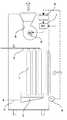
本実施形態は、本発明に係る加湿量制御方法を適用した気化式加湿器の一例を示すものであって、図1に示すように構成されている。
すなわち、本実施形態の気化式加湿器は、加湿飽和効率が80%以上の気化式加湿ユニット1と、この気化式加湿ユニット1に水を供給する給水ライン2と、気化式加湿ユニット1の下部に設置された排水貯留用の水槽3と、この水槽3に溜まった水を外部に排出する排水ライン4と、送風機5と、この送風機5の駆動源であるモータ6の回転を制御するINV7と、このINV7の電源周波数を決定して、INV7へ出力する制御器8と、加湿対象となる室内の湿度を測定し、その検出値を前記制御器8に送出する湿度センサ9とを備えている。
【0021】
そして、前記制御器8においては、予め設定された所望の湿度(設定湿度)と、湿度センサ9によって検出された現在の湿度(検出湿度)とから、両者の差を求め、その値に基づいて送風量を制御し、加湿対象となる室内の必要加湿量を供給することができるようにINV7の電源周波数を決定するように構成されている。このようにして送風機5のモータ6の回転数を制御することによって、気化式加湿ユニット1への通過風量を変化させることにより、室内への加湿量を制御するように構成されている。
【0022】
なお、湿度センサ9の検出値と送風量の関係は、図2に示す通りである。すなわち、検出湿度と設定湿度との差が少ないほど送風量を少なく、差が大きくなるほど送風量を多くするように制御するように構成されている。
【0023】
(1−2)作用
上記のような構成を有する本実施形態の気化式加湿器は、以下に述べるように作用する。なお、前記制御器8には、ユーザによって、加湿対象となる室内の湿度として所望する湿度が予め設定されているものとする。
【0024】
湿度センサ9によって、加湿対象となる室内の湿度が随時検出され、その検出値が制御器8に入力されると、制御器8において、予め設定された所望の湿度(設定湿度)と、湿度センサ9によって検出された湿度(検出湿度)との差が算出され、この値に基づいて、設定湿度を得るために必要な加湿量が算出され、その加湿量を得ることができるように送風量を制御すべく、INV7の電源周波数が決定される。そして、制御器8からINV7へその電源周波数が送出され、INV7によって送風機5のモータ6の回転が制御される。
【0025】
(1−3)効果
本実施形態の気化式加湿器によれば、比例加湿が可能となるため、室内の温度変化が緩やかなものとなる。また、気化式加湿ユニット1に供給する水として市水を用いた場合でも白い粉は発生しないため、クリーンルームにも適用することができる。さらに、低圧損であり、100V電源でも1500〜3000m3/hの装置が可能となるため、適用範囲が広くなり、より設置しやすくなる。また、湿度センサと制御器を設置するという簡単な構成であるため、部品が少なく、コストの低減が可能であるという利点もある。
【0026】
また、ワッシャー方式では、水滴を小さくして表面積を増やすか、噴霧量を多くして気液接触面積を増やしているが、本発明が対象とする加湿器は気化式(自然蒸発式)であり、親水性あるいは保水性を有する気化式加湿素材に水を滴下しているため、ワッシャー方式と同量の水を用いた場合でも水側の面積を大きくとることができ、気液接触面積が大きくとれるので、同等の加湿能力を有するワッシャー方式の加湿器と比較して、その容積を大幅に縮小することができる。
【0027】
さらに、本発明が対象とする加湿器は気化式であり、100%RH以上にならないため、水滴が飛散するという問題は生じない。また、従来から用いられている超音波加湿器で問題となっていた入力エネルギーの無駄がなく、水温の上昇がないため、室温が上昇するといった問題も生じない。
【0028】
(2)第2実施形態
本実施形態の加湿量制御システムは、上記第1実施形態の構成に、さらにファン残留運転回路を付加したものである。このファン残留運転回路の設置位置は、特に限定されず、電源系統内の所望の部位に設置すれば良い。
【0029】
なお、本実施形態において、ファン残留運転回路を設置した理由は以下の通りである。すなわち、通常、気化式加湿器素材は吸水性があるため、運転停止時にファン及び補給水を止めても、気化式加湿器素材は濡れた状態となり、その設置場所によっては臭いや菌の発生源となる。そのため、加湿器の運転を停止した後、ある定められた時間(例えば、10分間程度)、ファンのみを運転して気化式加湿器素材を乾燥させる必要がある。この乾燥作業を行うための制御回路、あるいはタイマーを本システム内に設置したものである。
【0030】
このように、ファン残留運転回路を付加することにより、気化式加湿器素材が濡れた状態のままとならないので、気化式加湿器素材が臭いや菌の発生源となることを防止することができる。
【0031】
(3)第3実施形態
第1実施形態の加湿量制御システムを適用した気化式加湿器の吸い込み口及び/又は吹き出し口に、その吸気及び排気の方向を自由に設定することができるフィンを設ける。そして、このフィンの方向を適宜調整することにより、たとえ加湿器の設置場所を変更した場合でも、吸気及び排気の方向を自由に設定することができるようになる。例えば、高さ方向が広い場合には、図3に示したように、送風機5の吹き出し方向を上向きとすることも可能である。
【0032】
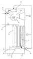
(4)第4実施形態
本実施形態の加湿量制御システムは、図4及び図5に示したように、気化式加湿ユニット1の下部に配設された水槽を循環水槽20とし、この循環水槽20に給水する給水ライン(請求項5における第1の給水ライン)21と、この循環水槽20から気化式加湿ユニット1の上部に加湿用水を供給する循環ライン(請求項5における第2の給水ライン)22が設けられている。なお、前記給水ライン21は、その先端部に取り付けられたボールタップ23によって、予め定められた水位(以下、定水位という)までの給水がなされるように構成されている。また、前記循環ライン22にはポンプ24が設けられ、循環水槽20から気化式加湿ユニット1への給水がなされるように構成されている。
【0033】
また、前記循環水槽20には、前記定水位より低い位置に排水口を設けた第1の排水ライン25と、循環水槽20の底部に排水口を設け、バルブ27によって開閉される第2の排水ライン26が配設されている。なお、前記第2の排水ライン26に設けられたバルブ27は、通常運転中は閉じられており、循環水槽20の清掃時等に開かれるようになっている。
【0034】
上記のような構成を有する本実施形態の気化式加湿器によれば、給水ライン21からは、ボールタップ23によって定水位までの給水がなされると共に、定水位より低い位置に排水口を設けた第1の排水ライン25によって定量排水がなされるので、補給水量の低減(排水量の削減)が可能となる。
【0035】
(5)第5実施形態
本実施形態においては、図6に示したように、気化式加湿ユニット1の吸い込み口側に加熱コイル11が配設され、この加熱コイル11を湿度センサ9により制御するように構成されている。
風量を一定とした場合には、吸い込み空気を加熱した方が装置としての加湿能力はアップするため、加湿負荷の多い部屋においては、吸い込み空気を加熱する方法を用いるほうが、設置台数の削減、小型化が可能となる。
【0036】
(6)第6実施形態
本実施形態においては、図7に示したように、湿度センサ9の検出値を制御器8に送出し、INV7への制御信号を得ると同時に、給水ライン2に設けられたバルブ(給水系統の制御弁)12の開度を調節する制御信号を得るように構成されている。
【0037】
加湿量を制御しているときに、一定量の補給水を供給することは水量的に無駄が多い。そこで、湿度センサ9による検出湿度と設定湿度との差に基づいて加湿量を算出し、その値に基づいて給水量を変更することにより、排水量を抑制することができる。
【0038】
(7)他の実施形態
なお、本発明は上述した実施形態に限定されるものではなく、以下に示すような各種態様も可能であり、具体的な各部材の形状、あるいは取付位置及び方法は適宜変更可能である。例えば、第1実施形態の加湿量制御システムを適用した気化式加湿器(図1参照)の吸い込み口及び/又は吹き出し口に、連動ON,OFFシャッター、あるいは風圧シャッターを設置することにより、運転停止時に、気化式加湿器素材に臭気や塵埃が入り込むのを防止することができる。
【0039】
また、本発明に係る加湿量制御方法を適用した気化式加湿器を、より清浄度の高いクリーンルーム等で使用する場合には、吹き出し口にHEPAフィルタを設置することにより、吸い込み空気の清浄化や、気化式加湿ユニットからの菌の発生、ファンからの発塵等を防止することができる。
【0040】
さらに、本発明に係る加湿量制御方法を適用した気化式加湿器は、加湿器としての機能だけでなく、常時水を滴下することにより気化式加湿器素材面での脱臭効果が得られるため、脱臭器として用いることもできる。
【0041】
なお、送風機のモータの回転数を制御する手段としては、上述したようなインバータの電源周波数の制御だけでなく、タップによる電源電圧の多段切換、あるいはサイリスタによる電圧制御等、種々の方法を用いることができる。
【0042】
【発明の効果】
上述したように、本発明によれば、高精度の加湿量制御を可能とし、騒音の発生を防止することができる気化式加湿における加湿量制御方法及び気化式加湿器を提供することができる。
【図面の簡単な説明】
【図1】本発明に係る加湿量制御方法を適用した気化式加湿器の第1実施形態の構成を示す図である。
【図2】検出湿度と設定湿度との差と、送風量(加湿量)との関係を示す図である。
【図3】本発明に係る加湿量制御方法を適用した気化式加湿器の第3実施形態の構成を示す模式図である。
【図4】本発明に係る加湿量制御方法を適用した気化式加湿器の第4実施形態の構成を示す模式図である。
【図5】図4に示した第4実施形態の要部拡大図である。
【図6】本発明に係る加湿量制御方法を適用した気化式加湿器の第5実施形態の構成を示す模式図である。
【図7】本発明に係る加湿量制御方法を適用した気化式加湿器の第6実施形態の構成を示す模式図である。
【符号の説明】
1…気化式加湿ユニット
2…給水ライン
3…水槽
4…排水ライン
5…送風機
6…モータ
7…INV
8…制御器
9…湿度センサ
11…加熱コイル
12…バルブ
20…循環水槽
21…給水ライン
22…循環ライン
23…ボールタップ
24…ポンプ
25…第1の排水ライン
26…第2の排水ライン
27…バルブ[0001]
BACKGROUND OF THE INVENTION
The present invention relates to a humidification amount control method and vaporization humidifier in vaporization humidification.
[0002]
[Prior art]
Conventionally, various humidifiers have been used in order to prevent troubles caused by static electricity due to air drying. The humidification method can be divided into a steam humidification method in which steam is directly sprayed, an air washer method, an ultrasonic method, a vaporization humidification method using a wet wall, or the like using evaporation from the water surface. The latter is deprived of heat of vaporization, so that the temperature on the air side is lowered, but it is not necessary to use high-level energy that generates steam, so that it is highly useful in terms of energy saving and safety.
[0003]
However, the ultrasonic humidifier has a problem that a residual component remains as a white powder after the water evaporates, and a problem that bacteria are generated due to an increase in water temperature, and an air washer. Also in the formula, if the spray droplets are made small in order to improve the humidification saturation efficiency, there is a problem that white powder is generated as in the ultrasonic humidifier. For this reason, in recent years, vaporizing humidifiers that do not generate water droplets have attracted attention.
[0004]
By the way, although the field which requires humidification does not ask | require general air conditioning and industrial air conditioning, especially in an industrial field, precise humidification amount control is requested | required in many cases. As such a humidification amount control method, for example, a technique shown in
[0005]
[Patent Document 1]
Japanese Patent Laid-Open No. 2001-317795
[Problems to be solved by the invention]
However, the conventional method for controlling the humidification amount as described above has the following problems. That is, since the humidifying amount control method in the conventional air washer type humidifier is ON / OFF control of the washer water pump, precise humidifying amount control cannot be performed, and the room temperature also fluctuates greatly.
[0007]
In addition, because of the washer system, the power of the washer pump is large, the humidification saturation efficiency is low (in other words, the humidification capacity is low), and the pressure loss of the eliminator is large, so the fan power is large and noise is high. It was.
[0008]
In addition, because city water is used as make-up water, there is a problem that “white powder” is produced when trying to reduce spray water droplets in order to increase humidification saturation efficiency. In the CR electronics factory, a HEPA filter is installed at the outlet. As a result, the pressure loss of the blower increased and the noise increased.
[0009]
The present invention has been proposed in order to solve the above-described problems of the prior art, and its purpose is to enable a highly accurate humidification control and to prevent generation of noise. It is providing the humidification amount control method and vaporization type humidifier in humidification.
[0010]
[Means for Solving the Problems]
In order to achieve the above object, the invention according to
[0011]
Moreover, the vaporization type humidifier of
[0012]
According to the first or second aspect of the invention having the above-described configuration, proportional humidification is possible, so that the temperature change in the room becomes gradual. Further, even when city water is used as water to be supplied to the vaporizing humidifier unit, white powder is not generated, so that it can be applied to a clean room. Further, since the gas-liquid contact area can be increased, the volume can be greatly reduced as compared with a washer-type humidifier having an equivalent humidification capacity.
[0013]
According to a third aspect of the present invention, in the vaporization type humidifier according to the second aspect, after the operation of the vaporization type humidifier is stopped, a control circuit for performing a drying operation of the vaporization type humidification unit for a predetermined time is provided. It is characterized by being.
According to the invention described in
[0014]
According to a fourth aspect of the present invention, in the vaporizing humidifier according to the second or third aspect, the direction of intake and exhaust is freely set in the suction port and / or the outlet of the vaporizing humidifier. It is characterized in that fins that can be used are provided.
According to the invention described in
[0015]
According to a fifth aspect of the present invention, in the vaporization type humidifier according to any one of the second to fourth aspects, a circulating water tank is provided in a lower part of the vaporization type humidification unit, and the water supply line is connected to the circulation line. A first water supply line for supplying water up to a predetermined water level in the water tank and a second water supply line for circulating and supplying humidification water to the vaporizing humidification unit, wherein the drainage line performs drainage due to overflow. 1 drainage line and a second drainage line that drains from the bottom of the circulating water tank, a portion of the humidifying water supplied to the circulating water tank is drained, and the other humidifying water is the vaporizing humidification It is configured to be circulated to the unit.
According to the invention described in
[0016]
According to a sixth aspect of the present invention, in the vaporization type humidifier according to any one of the second to fifth aspects, a heating coil is disposed on the suction port side of the vaporization type humidification unit. The temperature is controlled based on the detection value of the humidity sensor.
According to the invention described in
[0017]
According to a seventh aspect of the present invention, in the vaporizing humidifier according to any one of the second to sixth aspects, a water supply amount adjustment valve is provided in the water supply line, and the detected value of the humidity sensor In addition to being sent to the controller, a control signal for adjusting the opening of the valve is sent.
According to the invention described in
[0018]
Invention of
According to invention of
[0019]
DETAILED DESCRIPTION OF THE INVENTION
Hereinafter, specific embodiments of the present invention (hereinafter referred to as embodiments) will be described with reference to the drawings.
[0020]
(1) First Embodiment (1-1) Configuration This embodiment shows an example of a vaporizing humidifier to which a humidification amount control method according to the present invention is applied, and is configured as shown in FIG. ing.
That is, the vaporization type humidifier of this embodiment includes a vaporization
[0021]
Then, the
[0022]
In addition, the relationship between the detected value of the humidity sensor 9 and the air flow rate is as shown in FIG. That is, it is configured to control so that the smaller the difference between the detected humidity and the set humidity, the smaller the air flow rate, and the larger the difference, the greater the air flow rate.
[0023]
(1-2) Operation The vaporizing humidifier of the present embodiment having the above-described configuration operates as described below. In the
[0024]
When the humidity in the room to be humidified is detected at any time by the humidity sensor 9 and the detected value is input to the
[0025]
(1-3) Effect According to the vaporizing humidifier of the present embodiment, proportional humidification is possible, so that the temperature change in the room becomes gradual. Further, even when city water is used as the water to be supplied to the vaporizing
[0026]
In the washer method, the water droplets are reduced to increase the surface area, or the spray amount is increased to increase the gas-liquid contact area. However, the humidifier targeted by the present invention is a vaporization type (natural evaporation type). Since water is dripped onto a vaporizing humidifying material that has hydrophilicity or water retention, even when the same amount of water as the washer method is used, the water side area can be increased, and the gas-liquid contact area is large. Therefore, the volume can be greatly reduced as compared with a washer-type humidifier having an equivalent humidification capacity.
[0027]
Furthermore, the humidifier targeted by the present invention is a vaporization type and does not exceed 100% RH, so that there is no problem of water droplets scattering. In addition, there is no waste of input energy, which has been a problem with conventional ultrasonic humidifiers, and there is no increase in water temperature, so that the problem of an increase in room temperature does not occur.
[0028]
(2) Second Embodiment The humidification amount control system of the present embodiment is obtained by adding a fan residual operation circuit to the configuration of the first embodiment. The installation position of the fan residual operation circuit is not particularly limited, and may be installed at a desired site in the power supply system.
[0029]
In the present embodiment, the reason for installing the fan residual operation circuit is as follows. In other words, since the vaporizing humidifier material is water-absorbing, the vaporizing humidifier material is still wet even when the fan and makeup water are turned off when the operation is stopped. Depending on the installation location, the source of odors and bacteria It becomes. Therefore, after stopping the operation of the humidifier, it is necessary to drive only the fan for a predetermined time (for example, about 10 minutes) to dry the vaporizing humidifier material. A control circuit or a timer for performing this drying operation is installed in this system.
[0030]
In this way, by adding the fan residual operation circuit, the vaporizing humidifier material does not remain wet, so that the vaporizing humidifier material can be prevented from becoming a source of odors and bacteria. .
[0031]
(3) Third Embodiment A fin capable of freely setting the direction of intake and exhaust is provided at the suction port and / or the blowout port of the vaporizing humidifier to which the humidification amount control system of the first embodiment is applied. . Then, by appropriately adjusting the direction of the fins, the direction of intake and exhaust can be freely set even if the installation location of the humidifier is changed. For example, when the height direction is wide, as shown in FIG. 3, the blowing direction of the
[0032]
(4) Fourth Embodiment As shown in FIGS. 4 and 5, the humidification amount control system of this embodiment uses a water tank disposed in the lower part of the vaporizing
[0033]
The circulating
[0034]
According to the vaporizing humidifier of the present embodiment having the above-described configuration, the
[0035]
(5) Fifth Embodiment In the present embodiment, as shown in FIG. 6, the
When the air volume is constant, the humidification capacity of the device increases when the intake air is heated. Therefore, in a room with a high humidification load, the method of heating the intake air reduces the number of installed units and reduces the size. Can be realized.
[0036]
(6) Sixth Embodiment In the present embodiment, as shown in FIG. 7, the detected value of the humidity sensor 9 is sent to the
[0037]
When the amount of humidification is controlled, supplying a certain amount of makeup water is wasteful in terms of the amount of water. Therefore, the amount of drainage can be suppressed by calculating the humidification amount based on the difference between the humidity detected by the humidity sensor 9 and the set humidity, and changing the water supply amount based on the calculated value.
[0038]
(7) Other Embodiments The present invention is not limited to the above-described embodiments, and various modes as shown below are possible. Specific shapes of members, mounting positions and methods are as follows. It can be changed as appropriate. For example, the operation is stopped by installing a linked ON, OFF shutter, or wind pressure shutter at the inlet and / or outlet of the vaporizing humidifier (see FIG. 1) to which the humidification amount control system of the first embodiment is applied. Occasionally, odors and dust can be prevented from entering the vaporizing humidifier material.
[0039]
In addition, when the vaporizing humidifier to which the humidification amount control method according to the present invention is applied is used in a clean room or the like with a higher cleanliness, a suction air can be purified by installing a HEPA filter at the outlet. Moreover, generation | occurrence | production of the microbe from a vaporization type humidification unit, the dust generation from a fan, etc. can be prevented.
[0040]
Furthermore, the vaporization type humidifier to which the humidification amount control method according to the present invention is applied is not only a function as a humidifier but also a deodorizing effect on the vaporization type humidifier material surface by always dripping water, It can also be used as a deodorizer.
[0041]
In addition, as a means for controlling the rotation speed of the motor of the blower, various methods such as not only the control of the power supply frequency of the inverter as described above but also the multistage switching of the power supply voltage by the tap or the voltage control by the thyristor are used. Can do.
[0042]
【The invention's effect】
As described above, according to the present invention, it is possible to provide a humidification amount control method and a vaporization humidifier in vaporization humidification that enable highly accurate humidification amount control and can prevent noise generation.
[Brief description of the drawings]
FIG. 1 is a diagram showing a configuration of a first embodiment of a vaporizing humidifier to which a humidification amount control method according to the present invention is applied.
FIG. 2 is a diagram illustrating a relationship between a difference between a detected humidity and a set humidity and an air blowing amount (humidification amount).
FIG. 3 is a schematic diagram showing a configuration of a third embodiment of a vaporizing humidifier to which a humidification amount control method according to the present invention is applied.
FIG. 4 is a schematic diagram showing the configuration of a fourth embodiment of a vaporizing humidifier to which a humidification amount control method according to the present invention is applied.
FIG. 5 is an enlarged view of a main part of the fourth embodiment shown in FIG. 4;
FIG. 6 is a schematic diagram showing the configuration of a fifth embodiment of a vaporizing humidifier to which a humidification amount control method according to the present invention is applied.
FIG. 7 is a schematic diagram showing a configuration of a vaporizing humidifier to which a humidification amount control method according to the present invention is applied according to a sixth embodiment.
[Explanation of symbols]
DESCRIPTION OF
8 ... Controller 9 ...
Claims (8)
Translated fromJapanese予め設定された湿度と前記湿度センサによって検出された現在の湿度との差に基づいて送風量を制御し、加湿対象となる室内の必要加湿量を供給することができるように、前記送風機のモータの回転を制御することを特徴とする気化式加湿における加湿量制御方法。Using a vaporizing humidification unit having a humidification saturation efficiency of 80% or more, a blower, a controller that controls the rotation of a motor that is a drive source of the blower, and a humidity sensor that measures the humidity in a room to be humidified A humidification amount control method in vaporization humidification for controlling the humidification amount in a room to be humidified,
The motor of the blower is capable of controlling the amount of air flow based on the difference between the preset humidity and the current humidity detected by the humidity sensor, and supplying the required amount of humidification in the room to be humidified. A method for controlling the amount of humidification in vaporizing humidification, characterized by controlling the rotation of the gas.
前記制御器は、予め設定された湿度と前記湿度センサによって検出された現在の湿度との差に基づいて送風量を制御し、加湿対象となる室内の必要加湿量を供給することができるように、前記送風機のモータの回転を制御する信号を出力するように構成されていることを特徴とする気化式加湿器。A vaporizing humidifying unit having a humidification saturation efficiency of 80% or more, a water supply line and a draining line for supplying and draining humidifying water to the vaporizing humidifying unit, a blower, and a rotation of a motor that is a drive source of the blower are controlled. A controller that outputs a signal, and a humidity sensor that measures the humidity in the room to be humidified and sends the detected value to the controller,
The controller controls the air flow based on the difference between the preset humidity and the current humidity detected by the humidity sensor so that the required humidification amount in the room to be humidified can be supplied. The vaporizing humidifier is configured to output a signal for controlling the rotation of the motor of the blower.
前記給水ラインが、前記循環水槽の所定の水位まで給水するための第1の給水ラインと、前記気化式加湿ユニットに加湿用水を循環供給する第2の給水ラインとから構成され、
前記排水ラインが、オーバーフローによる排水を行う第1の排水ラインと、前記循環水槽の底部から排水を行う第2の排水ラインとから構成され、
前記循環水槽に給水された加湿用水の一部が排水され、他の加湿用水は前記気化式加湿ユニットに循環されるように構成されていることを特徴とする請求項2乃至請求項4のいずれか一に記載の気化式加湿器。A circulating water tank is provided at the bottom of the vaporizing humidification unit,
The water supply line is composed of a first water supply line for supplying water to a predetermined water level in the circulating water tank, and a second water supply line for circulating and supplying humidification water to the vaporizing humidification unit,
The drainage line is composed of a first drainage line that drains by overflow, and a second drainage line that drains from the bottom of the circulating water tank,
5. The structure according to claim 2, wherein a part of the humidifying water supplied to the circulating water tank is drained, and the other humidifying water is circulated to the vaporizing humidifier unit. A vaporizing humidifier according to claim 1.
Priority Applications (1)
| Application Number | Priority Date | Filing Date | Title |
|---|---|---|---|
| JP2003190312AJP2005024176A (en) | 2003-07-02 | 2003-07-02 | Humidification amount control method and vaporization type humidifier in vaporization type humidification |
Applications Claiming Priority (1)
| Application Number | Priority Date | Filing Date | Title |
|---|---|---|---|
| JP2003190312AJP2005024176A (en) | 2003-07-02 | 2003-07-02 | Humidification amount control method and vaporization type humidifier in vaporization type humidification |
Publications (1)
| Publication Number | Publication Date |
|---|---|
| JP2005024176Atrue JP2005024176A (en) | 2005-01-27 |
Family
ID=34188249
Family Applications (1)
| Application Number | Title | Priority Date | Filing Date |
|---|---|---|---|
| JP2003190312APendingJP2005024176A (en) | 2003-07-02 | 2003-07-02 | Humidification amount control method and vaporization type humidifier in vaporization type humidification |
Country Status (1)
| Country | Link |
|---|---|
| JP (1) | JP2005024176A (en) |
Cited By (19)
| Publication number | Priority date | Publication date | Assignee | Title |
|---|---|---|---|---|
| JP2008232138A (en)* | 2007-02-22 | 2008-10-02 | Tokyo Electric Power Co Inc:The | Intake air cooling system for gas turbine |
| JP2008241131A (en)* | 2007-03-27 | 2008-10-09 | Max Co Ltd | Humidifying ventilation system and humidified air supply system |
| JP2009192138A (en)* | 2008-02-14 | 2009-08-27 | Panasonic Corp | Liquid vaporizer and sauna device using the same |
| JP2011208891A (en)* | 2010-03-30 | 2011-10-20 | Apisute:Kk | Precision air conditioner |
| JP2011247454A (en)* | 2010-05-24 | 2011-12-08 | Taikisha Ltd | Air purification and humidification device |
| WO2014045668A1 (en)* | 2012-09-20 | 2014-03-27 | 三菱電機株式会社 | Humidifier and method of hydrophilization processing for humidification material |
| JP2016168341A (en)* | 2011-01-24 | 2016-09-23 | レスメド・リミテッドResMed Limited | humidifier |
| CN106241271A (en)* | 2016-08-23 | 2016-12-21 | 乌海市天惠矿山机械有限责任公司 | A kind of air cushion-belt conveyer automatic intelligent electric-control system |
| WO2017104073A1 (en)* | 2015-12-18 | 2017-06-22 | 三菱電機株式会社 | Humidification device |
| WO2018092626A1 (en) | 2016-11-17 | 2018-05-24 | セイコーエプソン株式会社 | Vaporization-type humidification unit, vaporization-type humidification unit control method, and sheet manufacture device |
| CN108151220A (en)* | 2017-12-27 | 2018-06-12 | 贵州大学 | A kind of split-type humidifier with dilatation |
| JP2018136106A (en)* | 2017-02-23 | 2018-08-30 | 伸和コントロールズ株式会社 | Air conditioner |
| JP2018136114A (en)* | 2017-10-16 | 2018-08-30 | 伸和コントロールズ株式会社 | Air conditioner |
| CN110749015A (en)* | 2019-10-31 | 2020-02-04 | 东莞市漫步者科技有限公司 | A humidifier and its shutdown control method |
| JP2020159654A (en)* | 2019-03-27 | 2020-10-01 | 三機工業株式会社 | Air conditioning system |
| KR102183009B1 (en)* | 2020-08-21 | 2020-11-25 | 주식회사 삼화에이스 | Control method of evaporative humidifier |
| WO2022041071A1 (en)* | 2020-08-27 | 2022-03-03 | 南京英维尔科技服务有限公司 | Humidification apparatus able to automatically rotate, and system |
| JP2022156152A (en)* | 2021-03-31 | 2022-10-14 | セイコーエプソン株式会社 | Humidifier and fiber processing device |
| CN115371175A (en)* | 2022-08-29 | 2022-11-22 | 珠海格力电器股份有限公司 | Fresh air mechanism, air conditioner and air conditioner control method |
- 2003
- 2003-07-02JPJP2003190312Apatent/JP2005024176A/enactivePending
Cited By (28)
| Publication number | Priority date | Publication date | Assignee | Title |
|---|---|---|---|---|
| JP2008232138A (en)* | 2007-02-22 | 2008-10-02 | Tokyo Electric Power Co Inc:The | Intake air cooling system for gas turbine |
| JP2008241131A (en)* | 2007-03-27 | 2008-10-09 | Max Co Ltd | Humidifying ventilation system and humidified air supply system |
| JP2009192138A (en)* | 2008-02-14 | 2009-08-27 | Panasonic Corp | Liquid vaporizer and sauna device using the same |
| JP2011208891A (en)* | 2010-03-30 | 2011-10-20 | Apisute:Kk | Precision air conditioner |
| JP2011247454A (en)* | 2010-05-24 | 2011-12-08 | Taikisha Ltd | Air purification and humidification device |
| JP2016168341A (en)* | 2011-01-24 | 2016-09-23 | レスメド・リミテッドResMed Limited | humidifier |
| US10307559B2 (en) | 2011-01-24 | 2019-06-04 | Resmed Limited | Humidifier |
| US11744979B2 (en) | 2011-01-24 | 2023-09-05 | ResMed Pty Ltd | Humidifier |
| CN104641182A (en)* | 2012-09-20 | 2015-05-20 | 三菱电机株式会社 | Hydrophilic treatment method of humidifier and humidifying material |
| JP5925326B2 (en)* | 2012-09-20 | 2016-05-25 | 三菱電機株式会社 | Humidifier, humidifier control method, humidifying material hydrophilization method |
| CN104641182B (en)* | 2012-09-20 | 2017-05-17 | 三菱电机株式会社 | Hydrophilic treatment method of humidifier and humidifying material |
| US9845961B2 (en) | 2012-09-20 | 2017-12-19 | Mitsubishi Electric Corporation | Humidifier and method of hydrophilization processing for humidifying material |
| WO2014045668A1 (en)* | 2012-09-20 | 2014-03-27 | 三菱電機株式会社 | Humidifier and method of hydrophilization processing for humidification material |
| WO2017104073A1 (en)* | 2015-12-18 | 2017-06-22 | 三菱電機株式会社 | Humidification device |
| JPWO2017104073A1 (en)* | 2015-12-18 | 2018-04-19 | 三菱電機株式会社 | Humidifier |
| CN106241271A (en)* | 2016-08-23 | 2016-12-21 | 乌海市天惠矿山机械有限责任公司 | A kind of air cushion-belt conveyer automatic intelligent electric-control system |
| US11214924B2 (en) | 2016-11-07 | 2022-01-04 | Seiko Epson Corporation | Vaporization type humidification unit, control method of vaporization type humidification unit, and sheet manufacturing apparatus |
| WO2018092626A1 (en) | 2016-11-17 | 2018-05-24 | セイコーエプソン株式会社 | Vaporization-type humidification unit, vaporization-type humidification unit control method, and sheet manufacture device |
| JP2018136106A (en)* | 2017-02-23 | 2018-08-30 | 伸和コントロールズ株式会社 | Air conditioner |
| JP2018136114A (en)* | 2017-10-16 | 2018-08-30 | 伸和コントロールズ株式会社 | Air conditioner |
| CN108151220A (en)* | 2017-12-27 | 2018-06-12 | 贵州大学 | A kind of split-type humidifier with dilatation |
| JP2020159654A (en)* | 2019-03-27 | 2020-10-01 | 三機工業株式会社 | Air conditioning system |
| JP7402614B2 (en) | 2019-03-27 | 2023-12-21 | 三機工業株式会社 | air conditioning system |
| CN110749015A (en)* | 2019-10-31 | 2020-02-04 | 东莞市漫步者科技有限公司 | A humidifier and its shutdown control method |
| KR102183009B1 (en)* | 2020-08-21 | 2020-11-25 | 주식회사 삼화에이스 | Control method of evaporative humidifier |
| WO2022041071A1 (en)* | 2020-08-27 | 2022-03-03 | 南京英维尔科技服务有限公司 | Humidification apparatus able to automatically rotate, and system |
| JP2022156152A (en)* | 2021-03-31 | 2022-10-14 | セイコーエプソン株式会社 | Humidifier and fiber processing device |
| CN115371175A (en)* | 2022-08-29 | 2022-11-22 | 珠海格力电器股份有限公司 | Fresh air mechanism, air conditioner and air conditioner control method |
Similar Documents
| Publication | Publication Date | Title |
|---|---|---|
| JP2005024176A (en) | Humidification amount control method and vaporization type humidifier in vaporization type humidification | |
| JP4396688B2 (en) | Air conditioner and operation method thereof | |
| JP5356731B2 (en) | A building air circulation system and a building having an air circulation structure. | |
| JP5092647B2 (en) | Ventilation air conditioner | |
| CN110749015A (en) | A humidifier and its shutdown control method | |
| WO2007108341A1 (en) | Sauna apparatus | |
| KR20070102972A (en) | Air conditioner humidified with condensate | |
| JP5272360B2 (en) | Ventilation air conditioner | |
| JP4672844B2 (en) | Humidification method and clean room device for clean room | |
| KR20090048240A (en) | Ceiling Mount Humidifier | |
| KR100970006B1 (en) | Fixed vaporized humidifier | |
| CN106440275A (en) | Air conditioning add-on for regulating indoor humidity | |
| JP5228344B2 (en) | Ventilation air conditioner | |
| JP2006275383A (en) | Moisture conditioning and air conditioning system | |
| CN207132469U (en) | A kind of air-conditioning | |
| JP3021732B2 (en) | Humidification control device for air conditioner | |
| JP7488203B2 (en) | Humidification device | |
| CN115342400A (en) | An air-conditioned range hood and its dehumidification control method | |
| CN202361533U (en) | Household purification and humidification fresh air machine | |
| JP2003254556A (en) | Image forming apparatus with air conditioner | |
| JP3588765B2 (en) | Humidifier | |
| CN104990186A (en) | Window type natural ventilation air humidifier | |
| JP7450144B2 (en) | How to stop water in liquid atomization equipment | |
| CN114838451B (en) | Control method of air conditioner and air conditioner | |
| KR200222086Y1 (en) | Movable Airconditioner |
Legal Events
| Date | Code | Title | Description |
|---|---|---|---|
| A621 | Written request for application examination | Free format text:JAPANESE INTERMEDIATE CODE: A621 Effective date:20060616 | |
| A977 | Report on retrieval | Free format text:JAPANESE INTERMEDIATE CODE: A971007 Effective date:20080822 | |
| A131 | Notification of reasons for refusal | Free format text:JAPANESE INTERMEDIATE CODE: A131 Effective date:20080902 | |
| A02 | Decision of refusal | Free format text:JAPANESE INTERMEDIATE CODE: A02 Effective date:20090106 |