JP2005021576A - Endoscopic magnetic anchor remote guidance system and endoscopic treatment method using magnetic anchor remote guidance system - Google Patents
Endoscopic magnetic anchor remote guidance system and endoscopic treatment method using magnetic anchor remote guidance systemDownload PDFInfo
- Publication number
- JP2005021576A JP2005021576AJP2003270395AJP2003270395AJP2005021576AJP 2005021576 AJP2005021576 AJP 2005021576AJP 2003270395 AJP2003270395 AJP 2003270395AJP 2003270395 AJP2003270395 AJP 2003270395AJP 2005021576 AJP2005021576 AJP 2005021576A
- Authority
- JP
- Japan
- Prior art keywords
- magnetic
- gripping member
- guidance system
- remote guidance
- gripping
- Prior art date
- Legal status (The legal status is an assumption and is not a legal conclusion. Google has not performed a legal analysis and makes no representation as to the accuracy of the status listed.)
- Pending
Links
Images


Landscapes
- Surgical Instruments (AREA)
Abstract
Translated fromJapaneseDescription
Translated fromJapanese本発明は、内視鏡観察下で病変部を切除する際に用いる、内視鏡用磁気アンカー遠隔誘導システム及び磁気アンカー遠隔誘導システムを用いた内視鏡による処置方法に関する。 The present invention relates to an endoscopic magnetic anchor remote guidance system and an endoscopic treatment method using the magnetic anchor remote guidance system used when excising a lesion under endoscopic observation.
従来、通常の手術において人体内部の病変部を切除する場合においては、把持鉗子を用いて病変部を持ち上げることにより病変部と隣接する正常組織との間隔を広げ、その状態で病変部と正常組織との間を切除している。しかし、例えば内視鏡的粘膜切除術(EMR)では、体内には内視鏡を一台しか挿入できないため、病変部を持ち上げることができず、注射針で病変部の周囲の正常粘膜に生理食塩水等を注入して病変部を浮き上がらせ、その状態で高周波ナイフやスネアなどを用いて病変部と正常粘膜の間の切除を行っていた。 Conventionally, when excising a lesion inside a human body in a normal operation, the distance between the lesion and the adjacent normal tissue is widened by lifting the lesion using a grasping forceps, and the lesion and the normal tissue are in that state. It is excised between. However, for example, in endoscopic mucosal resection (EMR), since only one endoscope can be inserted into the body, the lesion cannot be lifted, and the normal mucous membrane around the lesion cannot be lifted with an injection needle. Saline was injected to raise the lesion, and in that state, a high-frequency knife or snare was used to perform excision between the lesion and the normal mucosa.
しかし、このような従来の方法では、病変部を十分な位置まで持ち上げることができなかったため、病変部と正常組織との境界の切除部分を十分確保することができなかった。
また、病変部が扁平な形状である場合は、切除部分を作りだすことができないこともあった。However, in such a conventional method, the lesioned part could not be lifted to a sufficient position, and thus a sufficient excision part at the boundary between the lesioned part and the normal tissue could not be secured.
In addition, when the lesioned part has a flat shape, it may not be possible to create an excised part.
さらに、切除作業中において、すでに切除した病変部が正常組織上に落ち込むことにより内視鏡による視界を妨げることがあり、特に病変部が大きい場合に顕著であった。そのため、切除部分を見ることができず、盲目的に切除するために正常部分を損傷して穿孔などの合併症が発生したり、血管を損傷して大出血をきたし、また出血時も出血部位の確認ができず止血できないことから重篤な合併症を来すことも考えられ、より安全な装置や処置方法が求められていた。 Further, during the excision work, the already excised lesioned part may fall on the normal tissue, thereby obstructing the field of view by the endoscope, particularly when the lesioned part is large. For this reason, the excised part cannot be seen, and in order to remove it blindly, the normal part is damaged and complications such as perforation occur, blood vessels are damaged, and major bleeding occurs. Since it could not be confirmed and hemostasis could not be achieved, serious complications could occur, and a safer device and treatment method were required.
そこで本出願人は、これらの問題点を解決すべく、人体の臓器内部の病変部を把持する把持部材と、把持部材に接続された磁性体からなる磁気アンカーと、把持部材と磁気アンカーとを連結するひも状の連結部材と、人体の外部に配置され、磁界を発生して磁気アンカーに動力を与える磁気アンカー誘導装置と、を備え、磁気アンカー誘導装置が発生する磁界によって磁気アンカーに動力を与えて、把持部材によって把持された病変部を持ち上げることを特徴とする磁気磁気アンカー遠隔誘導システムを提案し、特許出願している(特願2002−268239号)。 Therefore, in order to solve these problems, the applicant of the present invention has a gripping member for gripping a lesioned part inside a human organ, a magnetic anchor made of a magnetic body connected to the gripping member, and a gripping member and a magnetic anchor. A string-like connecting member to be connected, and a magnetic anchor guiding device that is arranged outside the human body and generates a magnetic field to power the magnetic anchor, and the magnetic anchor generates power by using the magnetic field generated by the magnetic anchor guiding device. A magnetic magnetic anchor remote guidance system characterized by lifting a lesioned part grasped by a grasping member and applying for a patent has been filed (Japanese Patent Application No. 2002-268239).
本発明の目的は、上記特許出願の発明をさらに改良し、対象部位の処置を迅速かつ容易に行うことができるとともに、磁気アンカー誘導装置から磁界を発生させれば、把持部材によって把持された対象部位を確実に牽引でき、しかも組み立て作業が容易な内視鏡用磁気アンカー遠隔誘導システム、及び磁気アンカー遠隔誘導システムを用いた内視鏡による処置方法を提供することにある。 The object of the present invention is to further improve the invention of the above-mentioned patent application so that the target site can be treated quickly and easily, and if a magnetic field is generated from the magnetic anchor guiding device, the object gripped by the gripping member It is an object of the present invention to provide an endoscopic magnetic anchor remote guidance system that can reliably pull a site and that can be easily assembled, and an endoscopic treatment method using the magnetic anchor remote guidance system.
本発明の内視鏡用磁気アンカー遠隔誘導システムは、対象物内部の対象部位を把持可能な磁性体からなる磁性把持部材と、上記対象物外部に配置され、磁界を発生する磁気アンカー誘導装置と、を具備し、該磁気アンカー誘導装置が発生する磁界からの磁力により、上記対象部位を把持している上記磁性把持部材を移動させて、上記対象部位を所定方向に移動させることを特徴としている。 An endoscope magnetic anchor remote guidance system according to the present invention includes a magnetic gripping member made of a magnetic material capable of gripping a target portion inside a target, and a magnetic anchor guide device that is arranged outside the target and generates a magnetic field. The magnetic gripping member that holds the target part is moved by the magnetic force generated from the magnetic field generated by the magnetic anchor guiding device, and the target part is moved in a predetermined direction. .
上記磁性把持部材が開閉自在な複数の爪部を有しており、さらに、両端が開口する筒状をなし、上記磁性把持部材が挿脱可能な筒状締付部材と、該筒状締付部材と上記磁性把持部材の相対位置を変化させることにより、上記爪部を開閉させる開閉手段と、を具備するのが実際的である。 The magnetic gripping member has a plurality of claw portions that can be freely opened and closed, has a cylindrical shape with both ends open, and a cylindrical clamping member into which the magnetic gripping member can be inserted and removed, and the cylindrical clamping It is practical to include opening / closing means for opening and closing the claw portion by changing the relative position of the member and the magnetic gripping member.
上記開閉手段は、内視鏡の鉗子チャンネル内に挿通され操作部側から牽引操作可能な操作ワイヤと、この操作ワイヤと、上記鉗子チャンネル内に挿入されている上記磁性把持部材とを接続する、操作ワイヤに加える操作力で切断可能な牽引分離部材と、上記鉗子チャンネル内にあって、上記操作ワイヤの牽引力に抗して磁性把持部材を保持する、該磁性把持部材を押し出し可能な押出部材と、を備えているのが好ましい。 The opening / closing means connects an operation wire that is inserted into the forceps channel of the endoscope and that can be pulled from the operation unit side, and the operation wire and the magnetic gripping member that is inserted in the forceps channel. A pulling / separating member capable of being cut by an operating force applied to the operation wire; and a push-out member within the forceps channel for holding the magnetic gripping member against the pulling force of the operation wire and capable of pushing out the magnetic holding member. Are preferably provided.
上記磁気アンカー誘導装置は、発生する磁界によって磁力を生じさせて、該磁力によって、上記磁気アンカーを所定方向に移動させる磁気誘導部材と、該磁気誘導部材を特定の一平面内に配置したU字状のフレーム部材に沿って移動させる一平面内移動機構と、上記U字状のフレーム部材を上記一平面と直交する方向に相対移動させる一方向移動機構と、を有するのが実際的である。 The magnetic anchor guide device generates a magnetic force by a generated magnetic field, and moves the magnetic anchor in a predetermined direction by the magnetic force, and a U-shape in which the magnetic guide member is arranged in a specific plane. It is practical to have an in-plane moving mechanism that moves along the frame member and a unidirectional moving mechanism that relatively moves the U-shaped frame member in a direction perpendicular to the one plane.
本発明の磁気アンカー遠隔誘導システムを用いた内視鏡による処置方法は、対象物内部の対象部位を把持可能な磁性体からなる磁性把持部材を上記対象物内部に配設するステップ、該磁性把持部材により、上記対象物内部の対象部位を把持する把持ステップ、及び上記対象物外部に配置された磁気アンカー誘導装置から磁界を発生させ、該磁界から生じる磁力により上記磁性把持部材を移動させて、上記磁性把持部材に把持された対象部位を所定方向に移動させる移動ステップ、を有することを特徴としている。 An endoscopic treatment method using a magnetic anchor remote guidance system according to the present invention includes a step of disposing a magnetic gripping member made of a magnetic material capable of gripping a target portion inside a target object inside the target object, the magnetic gripping A member generates a magnetic field from a gripping step for gripping a target part inside the target object, and a magnetic anchor guiding device arranged outside the target object, and moves the magnetic gripping member by a magnetic force generated from the magnetic field, And a moving step for moving the target part held by the magnetic holding member in a predetermined direction.
上記磁性把持部材が開閉自在な複数の爪部を有しており、さらに、両端が開口する筒状をなし、上記磁性把持部材が挿脱可能な筒状締付部材と、該筒状締付部材と上記磁性把持部材の相対位置を変化させることにより、上記爪部を開閉させる開閉手段と、を具備するのが実際的である。 The magnetic gripping member has a plurality of claw portions that can be freely opened and closed, has a cylindrical shape with both ends open, and a cylindrical clamping member into which the magnetic gripping member can be inserted and removed, and the cylindrical clamping It is practical to include opening / closing means for opening and closing the claw portion by changing the relative position of the member and the magnetic gripping member.
上記開閉手段は、内視鏡の鉗子チャンネル内に挿通され操作部側から牽引操作可能な操作ワイヤと、この操作ワイヤと、上記鉗子チャンネル内に挿入されている上記磁性把持部材とを接続する、操作ワイヤに加える操作力で切断可能な牽引分離部材と、上記鉗子チャンネル内にあって、上記操作ワイヤの牽引力に抗して磁性把持部材を保持する、該磁性把持部材を押し出し可能な押出部材と、を備えているのが好ましい。 The opening / closing means connects an operation wire that is inserted into the forceps channel of the endoscope and that can be pulled from the operation unit side, and the operation wire and the magnetic gripping member that is inserted in the forceps channel. A pulling / separating member capable of being cut by an operating force applied to the operation wire; and a push-out member within the forceps channel for holding the magnetic gripping member against the pulling force of the operation wire and capable of pushing out the magnetic holding member. Are preferably provided.
本発明によると、対象部位の処置を迅速かつ容易に行うことができるとともに、磁気アンカー誘導装置から磁界を発生させれば、把持部材によって把持された対象部位を確実に牽引でき、しかも組み立て作業が容易になる。 According to the present invention, the target site can be quickly and easily treated, and if a magnetic field is generated from the magnetic anchor guiding device, the target site gripped by the gripping member can be reliably pulled, and assembly work can be performed. It becomes easy.
以下、本発明の一実施形態を、図1から図12を参照しながら説明する。
本実施形態の磁気アンカー遠隔誘導システムは、磁気アンカー装置10(磁性把持部材11、牽引分離部材14、筒状締付部材15からなる)と、磁気アンカー装置10の内視鏡20からの分離操作等を行う操作装置30と、磁気アンカー装置10を体外において吸引制御する(磁性把持部材11に磁力を及ぼす)磁気アンカー誘導装置40とからなるものである。Hereinafter, an embodiment of the present invention will be described with reference to FIGS.
The magnetic anchor remote guidance system of this embodiment includes a magnetic anchor device 10 (consisting of a
まず、図1から図3を参照して、磁気アンカー装置10の構成について説明する。
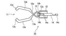
対称形状をなす磁性把持部材11は、強磁性材料板を折曲加工した弾性部材であり、自由状態においてその両側部の先端が接触するCリング状の基部12と、基部12の先端から前方に延びつつ拡開する一対の傾斜片13a、13aと、両傾斜片13a、13aの先端から延びる中間片13b、13bと、両中間片13b、13bの先端部を折曲して形成した爪部13c、13cとを具備している。さらに、基部12の後端部には挿入孔12aが穿設されている。強磁性材料の具体例としては、純鉄、鉄合金のほか、プラチナマグネット、希土類磁石、テルビウム・ディスプロシウム・鉄合金などの磁石がある。First, the configuration of the
The
牽引分離部材(開閉手段)14は棒状の部材であり、その先端には、磁性把持部材11の挿入孔12aを貫通する一対の挿入片14aと、挿入片14aの先端に設けられた、基部12の内面に係合して、挿入片14aが基部12から抜け出すのを防止する抜け止め部14bとが設けられている。さらに、牽引分離部材14の基端部には鈎部14cが形成されている。牽引分離部材14は、プラスチックやSUS等の金属材料から成形されており、所定の切断力以上の強い力を受けると切断される程度の強度である。 The pulling / separating member (opening / closing means) 14 is a rod-shaped member, and at the tip thereof, a pair of
図1から図3等に示す両端が開口する筒状締付部材15は、可撓性のある材料からなるものである。この筒状締付部材15の内径は、磁性把持部材11の基部12が嵌合可能な寸法となっている。 The
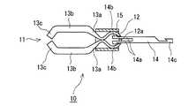
図1に示す状態(磁性把持部材11が筒状締付部材15内に嵌合していない状態)から、筒状締付部材15に対して牽引分離部材14を相対的に後方に引くと、図2に示すように、磁性把持部材11の基部12が内向きに弾性変形しながら筒状締付部材15の内部に引き込まれる。すると、基部12が弾性変形しながらその径が小さくなり、両傾斜片13aと両中間片13bが互いに離れる開状態となる。
図3に示すように、筒状締付部材15に対して牽引分離部材14をさらに相対的に後方に引くと、磁性把持部材11が内向きに弾性変形しながら筒状締付部材15の内部にさらに引き込まれ、その傾斜片13aが筒状締付部材15の先端開口部に接触し、両傾斜片13aと両中間片13bと両爪部13cが互いに接近する閉状態となる。From the state shown in FIG. 1 (the state in which the
As shown in FIG. 3, when the
図4は、磁気アンカー遠隔誘導システムを用いた切除術の実施に用いる内視鏡20を示している。
内視鏡20は周知のように、柔軟で可撓性を有し体内に挿入される挿入部21を有しており、その先端面22には、エア及び洗浄水を送るための送気送水ノズル(図示略)、切除部及びその周辺を照らすための照明窓(図示略)、直後に対物レンズと撮像素子が配置された、切除部及びその周辺を観察するための観察窓、並びに、図7等に示された鉗子チャネルCの出口23が設けられている。鉗子チャンネルCは挿入部21内に形成されており、その入口24aは鉗子口24の端面に形成されており、さらに、その出口23は、先端側が拡径するテーパ状となっている。FIG. 4 shows an
As is well known, the
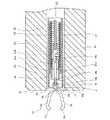
次に、図7を参照しながら、内視鏡20の鉗子チャンネルC内に挿入される操作装置30について説明する。
挿入管31は可撓性を有する筒状の部材であり、内視鏡20の鉗子口24の入口24aから鉗子チャンネルCに挿通可能である。さらに、その内径は、筒状締付部材15を挿入可能な寸法となっている。挿入管31の内部には、挿入管31に対して相対移動可能な筒状の挿入コイル(押出部材)(開閉手段)32が挿通されている。挿入コイル32の先端部には、大径部33aと小径部33bとからなる規制管(押出部材)(開閉手段)33の小径部33bが嵌合され、接着剤、はんだ、ロウなどによって、小径部33bが挿入コイル32の先端部に固着されている。Next, the
The
大径部33aの外径は挿入管31の内径より小さく、かつ、挿入コイル32の外径とほぼ同一に設定されている。さらに、大径部33aの内径は小径部33bの内径より大きく、筒状締付部材15の外形と略同一に設定されており、大径部33a内面の小径部33b内面との接続部には、規制管33の軸線に対して直交する環状段部33a1が形成されている(図7等参照)。 The outer diameter of the
鉗子チャンネルCに挿入された挿入コイル32の内側には、先端にフック部34が設けられた操作ワイヤ(開閉手段)35が、挿入コイル32と規制管33に対して相対移動可能に挿入されている。フック部34は、接着剤、はんだ、ロウ等によって、その基端部が操作ワイヤ35の先端部に固着されている。
さらに、挿入管31、挿入コイル32、及び操作ワイヤ35の各基端部は、操作装置30の操作部(図示略)に連結されており、互いに軸方向に相対移動可能となっている。
以上説明した、挿入管31、挿入コイル32、規制管33、フック部34、操作ワイヤ35、及び操作部により操作装置30が構成されている。Inside the
Furthermore, each base end part of the
The
次に、図5及び図6を用いて、患者Aの体外において磁性把持部材11を吸引制御する磁気アンカー誘導装置40の構成について説明する。
患者Aを載せる床板41aを具備するベッド41の両側部には、一対のXYステージ(一方向移動機構)42、42が配設されている。この一対のXYステージ42は、ベッド41の長手方向に沿って、両者42、42の該長手方向位置が常時同じになるように、直線的に往復移動するものである。さらに、ベッド41の上方には、ベッド41の長手方向と直交する平面内において互いに平行をなす、正面視略逆U字形の二つのレール44、45からなるフレーム/レール(一平面内移動機構)43が配設されており、このフレーム/レール43の両端部は、左右のXYステージ42にそれぞれ固定されている。内側のレール44には、磁性把持部材11を体外において吸引制御する(磁性把持部材11に磁力を及ぼす)磁気誘導部材46が摺動自在に装着されており、磁気誘導部材46は左右のXYステージ42の間を、レール45に沿って移動することができる。磁気誘導部材46は、鉄心にコイルを巻いた構造の電磁石47を基体48上に固定したものであり、その電磁石47は常時、患者A側を向いている(図5参照)。なお、磁気誘導部材46は、永久磁石と電磁石の組み合わせでもよく、また、永久磁石と電磁石を2個以上組み合わせたものでも良い。Next, the configuration of the magnetic
A pair of XY stages (one-way moving mechanisms) 42 and 42 are disposed on both sides of the
フレーム/レール43の外側のレール45には、フレーム/レール43全体の重量バランスを保つためのカウンターウエイト49がレール45に摺動自在に装着されている。カウンターウエイト49は、磁気誘導部材46の位置に応じて、その位置が変化する。例えば、磁気誘導部材46が患者Aの正面側に位置するときは、カウンターウエイト49は患者Aの背面側に位置し、磁気誘導部材46が患者Aの背面側にあるときは、カウンターウエイト49は患者Aの正面側に位置して、フレーム/レール43全体の重量バランスをとっている。
そして、以上説明した磁気誘導部材46、XYステージ42、フレーム/レール43により磁気アンカー誘導装置40が構成されている。A
The
次に、磁気アンカー遠隔誘導システムを用いた病変部Xの切除要領について説明する。
磁気アンカー遠隔誘導システムを用いた切除術の実施に先立っては、まず、図5及び図6に示すように、局所麻酔を施した患者Aをベッド41の床板41a上に横たわらせる。このとき、XYステージ42を操作して、フレーム/レール43のベッド41の長手方向位置を、患者Aの頭部A1とほぼ同じ位置にしておき、さらに、磁気誘導部材46及びカウンターウエイト49を所定の場所に位置させておく。
次に、XYステージ42を操作してフレーム/レール43を患者Aの正面側に配置させ、さらに、磁気誘導装置46をフレーム/レール43に沿って移動させて、磁気誘導部材46を切除術開始時位置に位置させる(図6参照)。Next, the excision procedure of the lesion X using the magnetic anchor remote guidance system will be described.
Prior to performing excision using the magnetic anchor remote guidance system, first, as shown in FIGS. 5 and 6, the patient A subjected to local anesthesia is laid on the
Next, the
次いで、図示を省略した可撓性を有するオーバーチューブを、患者Aの口から体内に挿入する。続いて、内視鏡20の挿入部21をオーバーチューブ内に挿入し、挿入部21の先端部をオーバーチューブの先端から突出させ、臓器(対象物)B(図8から図12参照)の病変部(対象部位)Xに近接させる(図示略)。このように、内視鏡20の挿入部21の先端を臓器B内に挿入すると、内視鏡20の挿入部21の先端面22に設けられた観察窓から得られた臓器B内の観察像が、図示を省略したテレビモニタに写し出される。 Next, a flexible overtube (not shown) is inserted from the mouth of patient A into the body. Subsequently, the
次いで、鉗子口24の入口24aから、先端部に注射針を具備するチューブ状の処置具(図示略)を鉗子チャンネルCに挿入して、その注射針を鉗子チャンネルCの出口23から突出させる。そして、注射針を病変部Xの周辺から臓器壁の粘膜下層B1に挿入して生理食塩水等を注入し、病変部Xを固有筋層B2から浮き上がらせておく(図8から図12参照)。 Next, a tube-like treatment tool (not shown) having an injection needle at the tip is inserted into the forceps channel C from the inlet 24 a of the
続いて、鉗子チャンネルCから該処置具を取り出す。次に、挿入管31、挿入コイル32、規制管33、フック部34、操作ワイヤ35、及び操作部を一体化した操作装置30を、鉗子口24から鉗子チャンネルCに挿入する。
この際、鉗子チャンネルCに操作装置30を挿入すると、操作装置30の操作部及び、挿入管31と挿入コイル32と操作ワイヤ35の基端部が鉗子口24の後方に突出する(図示略)。
また、筒状締付部材15は可撓性を有する材料から成形されており、かつ、挿入コイル32は屈曲自在なので、挿入部21が屈曲していても、これらの部材は鉗子チャンネルC内をスムーズに移動することができる。Subsequently, the treatment tool is taken out from the forceps channel C. Next, the
At this time, when the
Further, since the
操作装置30の先端が鉗子チャンネルCの先端部に到達したら、鉗子口24から突出している操作ワイヤ35の基端部を掴んで、操作ワイヤ35を操作してフック部34のみを内視鏡20の先端面22から突出させ、このフック部34に牽引分離部材14の鈎部14cを係合して、操作ワイヤ35を操作部側に引く。すると、図7に示すように、筒状締付部材15の基端部が規制管33の大径部33aに嵌合するとともに、牽引連結部材14、筒状締付部材15、及び磁性把持部材11の基部12が鉗子チャンネルC内に引き込まれ、磁気アンカー装置10と操作装置30が一体化する。 When the distal end of the
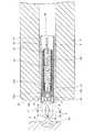
このように、内視鏡20に磁気アンカー装置10と操作装置30をセットしたら、図8に示すように、挿入コイル32の基端部を掴みながら挿入コイル32を挿入部21の先端側に移動させて、磁性把持部材11を病変部Xに近接させる。この状態で操作ワイヤ35を内視鏡20に対して相対的に後方に引くと、磁性把持部材11の基部12が筒状締付部材15内に引き込まれ、磁性把持部材11は図8に示す開状態となる。 When the
さらに操作ワイヤ35を後方に引くと、磁性把持部材11の基部12が筒状締付部材15内部の後方にさらに引き込まれ、かつ、傾斜片13aが筒状締付部材15の先端開口部に当接するので、磁性把持部材11の中間片13bが閉じて、両爪部13cにより病変部Xが確実に把持される(図9参照)。 When the
この状態で、操作ワイヤ35を上記切断力以上の強い力で後方に引くと、フック部34と係合している牽引分離部材14が、その中間部で切断され、その結果、磁気アンカー装置10が操作ワイヤ35から分離する(図10参照)。 In this state, when the
続いて、図11に示すように、患者Aの体外に配置されている磁気誘導部材46の発生磁界を強める。磁性把持部材11に生じる吸引力は磁性把持部材11の体積と密接な関係があり、磁性把持部材11の体積が大きいほど吸引力も大きくなる。例えば、磁性把持部材(材質は磁性SUS)11の寸法を、外形10mm、長さ17mm、体積754mm3とすると、磁気誘導部材46が発生する磁界の強さが0.604kOe(キロエルステッド)で、かつ、磁気誘導部材46から磁性把持部材11までの距離が10.5cmの場合、磁性把持部材11には12.1gの吸引力が生じる。
このように、磁性把持部材11の体積を所定の大きさ以上にすれば、磁性把持部材11には図11の上側を向く十分な大きさの吸引力が掛かり、磁性把持部材11に掴まれている病変部Xも同方向に十分な距離だけ持ち上げられる。Subsequently, as shown in FIG. 11, the generated magnetic field of the
As described above, when the volume of the magnetic gripping
このように、病変部Xを所望方向に所望距離だけ移動させると、病変部Xと正常組織との境界部に、十分な大きさの切除部分が形成されるので、挿入管31、挿入コイル32、及び操作ワイヤ35を内視鏡20から取り出し、図11に示すように、内視鏡20(図11では図示略)の鉗子チャネルCを利用して高周波メス50などの切開具を臓器B内に挿入し、病変部Xを粘膜とともに一方の端部側から切除する。
そして、病変部Xを一方の端部側から反対の端部側に切除すると、やがて、病変部X全体が完全に切除される(図12参照)。
なお、高周波メス50による切除作業時においては、切除領域が拡がるにつれて、高周波メス50の先端50aの位置の確認は、より容易となる。Thus, when the lesioned part X is moved by a desired distance in the desired direction, a sufficiently large excision part is formed at the boundary between the lesioned part X and the normal tissue. Then, the
Then, when the lesioned part X is excised from one end side to the opposite end side, the entire lesioned part X is eventually completely excised (see FIG. 12).
In the excision work with the high-
以上のように切除作業を終えると、正常組織から切り離された病変部Xは磁性把持部材11(磁気アンカー装置10)に把持されたままの状態となるので、病変部Xの紛失が防止される。
切除した病変部Xを回収するには、図12に示すように、内視鏡20(図12では図示略)の鉗子チャンネルCに、その先端部に開閉可能な一対の把持片61を具備し、さらに、その基端部に操作部(図示略)を具備する把持鉗子60を挿入する。そして、この操作部を操作して、把持片61を開放状態にした状態で牽引分離部材14に近接させ、その後に両把持片61を閉じて、両把持片61により牽引分離部材14を確実に把持する。そして、そのままの状態で内視鏡20を体内から抜き去り、病変部Xを磁気アンカー装置10とともに体外に取り出し、その後に、そして、切除した部分の縫合、消毒などの処置を行う。When the excision work is completed as described above, the lesioned part X separated from the normal tissue remains in the state of being gripped by the magnetic gripping member 11 (magnetic anchor device 10), so that the lesioned part X is prevented from being lost. .
In order to collect the excised lesion X, as shown in FIG. 12, the forceps channel C of the endoscope 20 (not shown in FIG. 12) is provided with a pair of
以上のように、本実施形態の磁気アンカー遠隔誘導システムを用いれば、磁性把持部材11が、従来の磁気アンカー遠隔誘導システムの磁気アンカーと把持部材の両方の機能を兼ねるので、従来の磁気アンカー遠隔誘導システムに比べて、部品点数の減少を図ることができ、磁気アンカー装置10の組み立て作業を容易に行うことができる。 As described above, when the magnetic anchor remote guidance system of this embodiment is used, the magnetic gripping
さらに、従来の磁気アンカー遠隔誘導システムでは連結ひも(連結部材)を必要としており、磁気誘導部材46から磁界を発生させると、磁気アンカーが臓器の内壁に接触するものの、連結ひもが緊張せず、その結果、把持部材に牽引力が掛からないということがあったが、本実施形態では連結ひも(連結部材)が不要となので、磁気誘導部材46から磁界を発生させれば、病変部Xを所望の方向に所望の距離だけ確実に移動させることができる。 Furthermore, the conventional magnetic anchor remote guidance system requires a connection string (connection member). When a magnetic field is generated from the
さらに、病変部Xを所望方向に十分な距離だけ移動させることができるため、病変部Xと正常組織との境界の切除部分を、容易かつ確実に十分な大きさで確保することができる。また、病変部Xが扁平な形状であっても、十分な大きさの切除部分を作りだすことができるので、このような場合であっても、病変部Xを容易に切除することが可能となる。 Further, since the lesioned part X can be moved in a desired direction by a sufficient distance, the excised part at the boundary between the lesioned part X and the normal tissue can be easily and reliably secured with a sufficient size. Even if the lesioned part X has a flat shape, a sufficiently large excision part can be created. Even in such a case, the lesioned part X can be easily excised. .
さらに、病変部Xは磁性把持部材11により持ち上げられるため、切除部分を十分確保することができ、すでに切除した病変部Xが固有筋層B2上に落ち込むことを防止できる。
また、任意の位置に磁性把持部材11を配置できるため、切除した病変部Xにより内視鏡20の視界が妨げられることがない。Furthermore, since the lesioned part X is lifted by the magnetic gripping
Further, since the magnetic gripping
本発明について上記実施形態を参照しつつ説明したが、本発明は上記実施形態に限定されるものではなく、改良の目的または本発明の思想の範囲内において改良または変更が可能である。例えば、基部12の形状を変更した上で、傾斜片13aと中間片13bと爪部13cの一体物を3個以上としてもよい。このようにすれば、磁性把持部材11の体積が大きくなるので、磁性把持部材11に掛かる吸引力が大きくなる。 Although the present invention has been described with reference to the above embodiment, the present invention is not limited to the above embodiment, and can be improved or changed within the scope of the purpose of the improvement or the idea of the present invention. For example, after changing the shape of the
10 磁気アンカー装置
11 磁性把持部材
12 基部
12a 挿入孔
13a 傾斜片
13b 中間片
13c 爪部
14 牽引分離部材(開閉手段)
14a 挿入片
14b 抜け止め部
14c 鈎部
15 筒状締付部材
20 内視鏡
21 挿入部
22 先端面
23 鉗子チャンネルの出口
24 鉗子口
24a 入口
30 操作装置
31 挿入管
32 挿入コイル(押出部材)(開閉手段)
33 規制管(押出部材)(開閉手段)
33a 大径部
33a1 環状段部
33b 小径部
34 フック部
35 操作ワイヤ(開閉手段)
40 磁気アンカー誘導装置
41 ベッド
41a 床板
42 XYステージ(一方向移動機構)
43 フレーム/レール(一平面内移動機構)
44 45 レール
46 磁気誘導部材
47 電磁石
48 基体
49 カウンターウェイト
50 高周波メス
50a 先端部
60 把持鉗子
61 把持片
A 患者
A1 頭部
B 臓器(対象物)
B1 粘膜下層
B2 固有筋層
C 鉗子チャンネル
P 重力
X 病変部(対象部位)
DESCRIPTION OF
33 Regulatory tube (extrusion member) (opening / closing means)
33a Large diameter portion 33a1
40 Magnetic
43 Frame / rail (moving mechanism in one plane)
44 45
B1 Submucosal layer B2 Eigenmuscle layer C Forceps channel P Gravity X Lesions (target site)
Claims (7)
Translated fromJapanese上記対象物外部に配置され、磁界を発生する磁気アンカー誘導装置と、を具備し、
該磁気アンカー誘導装置が発生する磁界からの磁力により、上記対象部位を把持している上記磁性把持部材を移動させて、上記対象部位を所定方向に移動させることを特徴とする内視鏡用磁気アンカー遠隔誘導システム。A magnetic gripping member made of a magnetic material capable of gripping a target part inside the target; and
A magnetic anchor guiding device that is arranged outside the object and generates a magnetic field,
Endoscopic magnetism characterized by moving the target part in a predetermined direction by moving the magnetic gripping member that holds the target part by the magnetic force generated by the magnetic anchor guiding device. Anchor remote guidance system.
上記磁性把持部材が開閉自在な複数の爪部を有しており、さらに、
両端が開口する筒状をなし、上記磁性把持部材が挿脱可能な筒状締付部材と、
該筒状締付部材と上記磁性把持部材の相対位置を変化させることにより、上記爪部を開閉させる開閉手段と、
を具備する内視鏡用磁気アンカー遠隔誘導システム。In the endoscope magnetic anchor remote guidance system according to claim 1,
The magnetic gripping member has a plurality of claw parts that can be freely opened and closed, and
A cylindrical fastening member having both ends opened and a cylindrical clamping member into which the magnetic gripping member can be inserted and removed;
Opening and closing means for opening and closing the claw portion by changing a relative position of the cylindrical fastening member and the magnetic gripping member;
An endoscope magnetic anchor remote guidance system comprising:
上記開閉手段は、
内視鏡の鉗子チャンネル内に挿通され操作部側から牽引操作可能な操作ワイヤと、
この操作ワイヤと、上記鉗子チャンネル内に挿入されている上記磁性把持部材とを接続する、操作ワイヤに加える操作力で切断可能な牽引分離部材と、
上記鉗子チャンネル内にあって、上記操作ワイヤの牽引力に抗して磁性把持部材を保持する、該磁性把持部材を押し出し可能な押出部材と、
を備えている内視鏡用磁気アンカー遠隔誘導システム。The endoscope magnetic anchor remote guidance system according to claim 2,
The opening / closing means is
An operation wire that is inserted into the forceps channel of the endoscope and can be pulled from the operation unit side;
A pulling / separating member that connects the operation wire and the magnetic gripping member inserted in the forceps channel and can be cut by an operation force applied to the operation wire;
An extruding member that is in the forceps channel and holds the magnetic gripping member against the pulling force of the operation wire, and can push out the magnetic gripping member;
A magnetic anchor remote guidance system for an endoscope.
上記磁気アンカー誘導装置は、
発生する磁界によって磁力を生じさせて、該磁力によって、上記磁気アンカーを所定方向に移動させる磁気誘導部材と、
該磁気誘導部材を特定の一平面内に配置したU字状のフレーム部材に沿って移動させる一平面内移動機構と、
上記U字状のフレーム部材を上記一平面と直交する方向に相対移動させる一方向移動機構と、
を有する内視鏡用磁気アンカー遠隔誘導システム。In the magnetic anchor remote guidance system for endoscopes according to any one of claims 1 to 3,
The magnetic anchor guiding device is
A magnetic induction member that generates a magnetic force by a generated magnetic field and moves the magnetic anchor in a predetermined direction by the magnetic force;
An in-plane movement mechanism for moving the magnetic induction member along a U-shaped frame member arranged in a specific plane;
A one-way moving mechanism for relatively moving the U-shaped frame member in a direction orthogonal to the one plane;
An endoscopic magnetic anchor remote guidance system.
該磁性把持部材により、上記対象物内部の対象部位を把持する把持ステップ、及び
上記対象物外部に配置された磁気アンカー誘導装置から磁界を発生させ、該磁界から生じる磁力により上記磁性把持部材を移動させて、上記磁性把持部材に把持された対象部位を所定方向に移動させる移動ステップ、
を有することを特徴とする磁気アンカー遠隔誘導システムを用いた内視鏡による処置方法。Disposing a magnetic gripping member made of a magnetic material capable of gripping a target portion inside the target object inside the target object;
The magnetic gripping member generates a magnetic field from a gripping step for gripping a target portion inside the target object and a magnetic anchor guiding device disposed outside the target object, and the magnetic gripping member is moved by the magnetic force generated from the magnetic field. A moving step of moving the target part gripped by the magnetic gripping member in a predetermined direction;
A treatment method using an endoscope using a magnetic anchor remote guidance system.
上記磁性把持部材が開閉自在な複数の爪部を有しており、さらに、
両端が開口する筒状をなし、上記磁性把持部材が挿脱可能な筒状締付部材と、該筒状締付部材に接続された開閉手段、とを具備しており、
上記把持ステップが、
上記開閉手段を操作して、上記磁性把持部材の上記筒状締付部材に対する相対位置を変化させることにより、上記爪部を閉じるステップである、磁気アンカー遠隔誘導システムを用いた内視鏡による処置方法。An endoscopic treatment method using the magnetic anchor remote guidance system according to claim 5,
The magnetic gripping member has a plurality of claw parts that can be freely opened and closed, and
A cylindrical fastening member having both ends open, and a cylindrical fastening member into which the magnetic gripping member can be inserted and removed; and an opening / closing means connected to the tubular fastening member,
The gripping step is
Endoscopic treatment using a magnetic anchor remote guidance system, which is a step of closing the claw portion by operating the opening / closing means to change the relative position of the magnetic gripping member to the cylindrical fastening member. Method.
上記開閉手段は、
内視鏡の鉗子チャンネル内に挿通され操作部側から牽引操作可能な操作ワイヤと、
この操作ワイヤと、上記鉗子チャンネル内に挿入されている上記磁性把持部材とを接続する、操作ワイヤに加える操作力で切断可能な牽引分離部材と、
上記鉗子チャンネル内にあって、上記操作ワイヤの牽引力に抗して磁性把持部材を保持する、該磁性把持部材を押し出し可能な押出部材と、
を備えている磁気アンカー遠隔誘導システムを用いた内視鏡による処置方法。
An endoscopic treatment method using the magnetic anchor remote guidance system according to claim 6,
The opening / closing means is
An operation wire that is inserted into the forceps channel of the endoscope and can be pulled from the operation unit side;
A pulling / separating member that connects the operation wire and the magnetic gripping member inserted in the forceps channel and can be cut by an operation force applied to the operation wire;
An extruding member that is in the forceps channel and holds the magnetic gripping member against the pulling force of the operation wire, and can push out the magnetic gripping member;
An endoscopic treatment method using a magnetic anchor remote guidance system comprising:
Priority Applications (1)
| Application Number | Priority Date | Filing Date | Title |
|---|---|---|---|
| JP2003270395AJP2005021576A (en) | 2003-07-02 | 2003-07-02 | Endoscopic magnetic anchor remote guidance system and endoscopic treatment method using magnetic anchor remote guidance system |
Applications Claiming Priority (1)
| Application Number | Priority Date | Filing Date | Title |
|---|---|---|---|
| JP2003270395AJP2005021576A (en) | 2003-07-02 | 2003-07-02 | Endoscopic magnetic anchor remote guidance system and endoscopic treatment method using magnetic anchor remote guidance system |
Publications (1)
| Publication Number | Publication Date |
|---|---|
| JP2005021576Atrue JP2005021576A (en) | 2005-01-27 |
Family
ID=34190353
Family Applications (1)
| Application Number | Title | Priority Date | Filing Date |
|---|---|---|---|
| JP2003270395APendingJP2005021576A (en) | 2003-07-02 | 2003-07-02 | Endoscopic magnetic anchor remote guidance system and endoscopic treatment method using magnetic anchor remote guidance system |
Country Status (1)
| Country | Link |
|---|---|
| JP (1) | JP2005021576A (en) |
Cited By (22)
| Publication number | Priority date | Publication date | Assignee | Title |
|---|---|---|---|---|
| JP2007097663A (en)* | 2005-09-30 | 2007-04-19 | Sumitomo Bakelite Co Ltd | Clip for endoscope |
| JP2007130408A (en)* | 2005-11-07 | 2007-05-31 | River Seiko:Kk | Endoscopic clip device |
| JP2007536012A (en)* | 2004-05-05 | 2007-12-13 | ボストン サイエンティフィック リミテッド | Instrument and method for magnetically manipulating endovascular instruments |
| JP2009504250A (en)* | 2005-08-10 | 2009-02-05 | ガイディッド デリバリー システムズ インコーポレイテッド | Method and apparatus for deploying a tissue anchor |
| JP2011524793A (en)* | 2008-06-19 | 2011-09-08 | ボストン サイエンティフィック サイムド, インコーポレイテッド | Hemostasis clipping device and method |
| JP2012517258A (en)* | 2009-02-06 | 2012-08-02 | バイオテク イノヴェイションズ リミターダ | Guide / remote traction system for minimally invasive surgery |
| JP2016171911A (en)* | 2015-03-17 | 2016-09-29 | 株式会社パイオラックスメディカルデバイス | Medical gripper and its manufacturing method |
| US9616197B2 (en) | 2009-01-20 | 2017-04-11 | Ancora Heart, Inc. | Anchor deployment devices and related methods |
| US9636107B2 (en) | 2002-06-13 | 2017-05-02 | Ancora Heart, Inc. | Devices and methods for heart valve repair |
| JP2017169676A (en)* | 2016-03-22 | 2017-09-28 | 株式会社日進製作所 | Medical clip and position specification tool thereof |
| US10010370B2 (en) | 2013-03-14 | 2018-07-03 | Levita Magnetics International Corp. | Magnetic control assemblies and systems therefor |
| US10058321B2 (en) | 2015-03-05 | 2018-08-28 | Ancora Heart, Inc. | Devices and methods of visualizing and determining depth of penetration in cardiac tissue |
| US10130381B2 (en) | 2013-03-12 | 2018-11-20 | Levita Magnetics International Corp. | Grasper with magnetically-controlled positioning |
| US10537348B2 (en) | 2014-01-21 | 2020-01-21 | Levita Magnetics International Corp. | Laparoscopic graspers and systems therefor |
| CN111358413A (en)* | 2018-12-26 | 2020-07-03 | 深圳开立生物医疗科技股份有限公司 | Joint, locking and separating mechanism, endoscope and endoscope system |
| US10905511B2 (en) | 2015-04-13 | 2021-02-02 | Levita Magnetics International Corp. | Grasper with magnetically-controlled positioning |
| US11020137B2 (en) | 2017-03-20 | 2021-06-01 | Levita Magnetics International Corp. | Directable traction systems and methods |
| US11413026B2 (en) | 2007-11-26 | 2022-08-16 | Attractive Surgical, Llc | Magnaretractor system and method |
| US11583354B2 (en) | 2015-04-13 | 2023-02-21 | Levita Magnetics International Corp. | Retractor systems, devices, and methods for use |
| US11672524B2 (en) | 2019-07-15 | 2023-06-13 | Ancora Heart, Inc. | Devices and methods for tether cutting |
| JP2023543425A (en)* | 2020-09-22 | 2023-10-16 | ボストン サイエンティフィック サイムド,インコーポレイテッド | Medical system with removable end effector with articulation |
| US12262971B2 (en) | 2016-01-08 | 2025-04-01 | Levita Magnetics International Corp. | One-operator surgical system and methods of use |
- 2003
- 2003-07-02JPJP2003270395Apatent/JP2005021576A/enactivePending
Cited By (36)
| Publication number | Priority date | Publication date | Assignee | Title |
|---|---|---|---|---|
| US9636107B2 (en) | 2002-06-13 | 2017-05-02 | Ancora Heart, Inc. | Devices and methods for heart valve repair |
| JP2007536012A (en)* | 2004-05-05 | 2007-12-13 | ボストン サイエンティフィック リミテッド | Instrument and method for magnetically manipulating endovascular instruments |
| JP4814874B2 (en)* | 2004-05-05 | 2011-11-16 | ボストン サイエンティフィック リミテッド | Instrument and method for magnetically manipulating endovascular instruments |
| JP2009504250A (en)* | 2005-08-10 | 2009-02-05 | ガイディッド デリバリー システムズ インコーポレイテッド | Method and apparatus for deploying a tissue anchor |
| JP2007097663A (en)* | 2005-09-30 | 2007-04-19 | Sumitomo Bakelite Co Ltd | Clip for endoscope |
| JP2007130408A (en)* | 2005-11-07 | 2007-05-31 | River Seiko:Kk | Endoscopic clip device |
| US11413026B2 (en) | 2007-11-26 | 2022-08-16 | Attractive Surgical, Llc | Magnaretractor system and method |
| US11413025B2 (en) | 2007-11-26 | 2022-08-16 | Attractive Surgical, Llc | Magnaretractor system and method |
| JP2011524793A (en)* | 2008-06-19 | 2011-09-08 | ボストン サイエンティフィック サイムド, インコーポレイテッド | Hemostasis clipping device and method |
| US9616197B2 (en) | 2009-01-20 | 2017-04-11 | Ancora Heart, Inc. | Anchor deployment devices and related methods |
| US10625047B2 (en) | 2009-01-20 | 2020-04-21 | Ancora Heart, Inc. | Anchor deployment devices and related methods |
| US9844391B2 (en) | 2009-02-06 | 2017-12-19 | Levita Magnetics International Corp. | Remote traction and guidance system for mini-invasive surgery |
| US9974546B2 (en) | 2009-02-06 | 2018-05-22 | Levita Magnetics International Corp. | Remote traction and guidance system for mini-invasive surgery |
| JP2012517258A (en)* | 2009-02-06 | 2012-08-02 | バイオテク イノヴェイションズ リミターダ | Guide / remote traction system for minimally invasive surgery |
| US11357525B2 (en) | 2013-03-12 | 2022-06-14 | Levita Magnetics International Corp. | Grasper with magnetically-controlled positioning |
| US12329402B2 (en) | 2013-03-12 | 2025-06-17 | Levita Magnetics International Corp. | Grasper with magnetically-controlled positioning |
| US10130381B2 (en) | 2013-03-12 | 2018-11-20 | Levita Magnetics International Corp. | Grasper with magnetically-controlled positioning |
| US10010370B2 (en) | 2013-03-14 | 2018-07-03 | Levita Magnetics International Corp. | Magnetic control assemblies and systems therefor |
| US11730476B2 (en) | 2014-01-21 | 2023-08-22 | Levita Magnetics International Corp. | Laparoscopic graspers and systems therefor |
| US12171433B2 (en) | 2014-01-21 | 2024-12-24 | Levita Magnetics International Corp. | Laparoscopic graspers and systems therefor |
| US10537348B2 (en) | 2014-01-21 | 2020-01-21 | Levita Magnetics International Corp. | Laparoscopic graspers and systems therefor |
| US12102316B2 (en) | 2015-03-05 | 2024-10-01 | Ancora Heart, Inc. | Devices and methods of visualizing and determining depth of penetration in cardiac tissue |
| US10980529B2 (en) | 2015-03-05 | 2021-04-20 | Ancora Heart, Inc. | Devices and methods of visualizing and determining depth of penetration in cardiac tissue |
| US10058321B2 (en) | 2015-03-05 | 2018-08-28 | Ancora Heart, Inc. | Devices and methods of visualizing and determining depth of penetration in cardiac tissue |
| JP2016171911A (en)* | 2015-03-17 | 2016-09-29 | 株式会社パイオラックスメディカルデバイス | Medical gripper and its manufacturing method |
| US10905511B2 (en) | 2015-04-13 | 2021-02-02 | Levita Magnetics International Corp. | Grasper with magnetically-controlled positioning |
| US11751965B2 (en) | 2015-04-13 | 2023-09-12 | Levita Magnetics International Corp. | Grasper with magnetically-controlled positioning |
| US11583354B2 (en) | 2015-04-13 | 2023-02-21 | Levita Magnetics International Corp. | Retractor systems, devices, and methods for use |
| US12357407B2 (en) | 2015-04-13 | 2025-07-15 | Levita Magnetics International Corp. | Grasper with magnetically-controlled positioning |
| US12262971B2 (en) | 2016-01-08 | 2025-04-01 | Levita Magnetics International Corp. | One-operator surgical system and methods of use |
| JP2017169676A (en)* | 2016-03-22 | 2017-09-28 | 株式会社日進製作所 | Medical clip and position specification tool thereof |
| US11020137B2 (en) | 2017-03-20 | 2021-06-01 | Levita Magnetics International Corp. | Directable traction systems and methods |
| US12185962B2 (en) | 2017-03-20 | 2025-01-07 | Levita Magnetics International Corp. | Directable traction systems and methods |
| CN111358413A (en)* | 2018-12-26 | 2020-07-03 | 深圳开立生物医疗科技股份有限公司 | Joint, locking and separating mechanism, endoscope and endoscope system |
| US11672524B2 (en) | 2019-07-15 | 2023-06-13 | Ancora Heart, Inc. | Devices and methods for tether cutting |
| JP2023543425A (en)* | 2020-09-22 | 2023-10-16 | ボストン サイエンティフィック サイムド,インコーポレイテッド | Medical system with removable end effector with articulation |
Similar Documents
| Publication | Publication Date | Title |
|---|---|---|
| JP2005021576A (en) | Endoscopic magnetic anchor remote guidance system and endoscopic treatment method using magnetic anchor remote guidance system | |
| JP4338440B2 (en) | Magnetic guidance means guidance system for endoscope | |
| JP4147315B2 (en) | Magnetic anchor remote guidance system | |
| JP4320214B2 (en) | Endoscopic grasping device and magnetic anchor remote guidance system | |
| JP4373720B2 (en) | Endoscope anchor remote guidance system | |
| JP4338437B2 (en) | Endoscope guidance means remote guidance system | |
| JP4349850B2 (en) | Endoscope anchor remote guidance system | |
| JP4360838B2 (en) | Endoscope anchor remote guidance system | |
| JP4349847B2 (en) | Endoscopic magnetic anchor remote guidance system | |
| JP4320202B2 (en) | Endoscope anchor remote guidance system and endoscope guidance device | |
| JP4320208B2 (en) | Magnetic guidance means remote guidance system with gravity direction visual recognition device and endoscope magnetic guidance device with gravity direction visual recognition device | |
| JP4338441B2 (en) | Endoscope guidance means guidance system and endoscope guidance device | |
| JP4320205B2 (en) | Endoscope guidance means guidance system and endoscope guidance device | |
| JP4320201B2 (en) | Endoscope gravity guidance device | |
| JP4338443B2 (en) | Endoscope gripping device | |
| JP2004358024A (en) | Endoscope anchor remote guidance system and endoscope treatment method using anchor remote guidance system | |
| JP4341739B2 (en) | Endoscope guidance means guidance system and endoscope guidance device | |
| JP4243977B2 (en) | Endoscope anchor guidance system | |
| JP4360835B2 (en) | Endoscopic grasping device and magnetic anchor remote guidance system | |
| JP4373714B2 (en) | Endoscope gripping device | |
| JP4341740B2 (en) | Endoscope guidance means guidance system and endoscope guidance device | |
| JP4349859B2 (en) | Endoscope anchor remote guidance system | |
| JP4462482B2 (en) | Magnetic anchor remote guidance system | |
| JP4338420B2 (en) | Endoscope gripping device | |
| JP2004358136A (en) | Endoscope anchor remote guidance system and endoscope treatment method using anchor remote guidance system |
Legal Events
| Date | Code | Title | Description |
|---|---|---|---|
| A621 | Written request for application examination | Free format text:JAPANESE INTERMEDIATE CODE: A621 Effective date:20060529 | |
| RD04 | Notification of resignation of power of attorney | Free format text:JAPANESE INTERMEDIATE CODE: A7424 Effective date:20070625 | |
| A711 | Notification of change in applicant | Free format text:JAPANESE INTERMEDIATE CODE: A712 Effective date:20080501 | |
| A977 | Report on retrieval | Free format text:JAPANESE INTERMEDIATE CODE: A971007 Effective date:20081009 | |
| A131 | Notification of reasons for refusal | Free format text:JAPANESE INTERMEDIATE CODE: A131 Effective date:20081028 | |
| A521 | Written amendment | Free format text:JAPANESE INTERMEDIATE CODE: A523 Effective date:20081224 | |
| A02 | Decision of refusal | Free format text:JAPANESE INTERMEDIATE CODE: A02 Effective date:20090127 |